EP3350426B1 - Apparatus and method for cleaning diesel particulate filters - Google Patents
Apparatus and method for cleaning diesel particulate filters Download PDFInfo
- Publication number
- EP3350426B1 EP3350426B1 EP16778913.0A EP16778913A EP3350426B1 EP 3350426 B1 EP3350426 B1 EP 3350426B1 EP 16778913 A EP16778913 A EP 16778913A EP 3350426 B1 EP3350426 B1 EP 3350426B1
- Authority
- EP
- European Patent Office
- Prior art keywords
- filter
- liquid
- clean
- cleaning
- dirty
- Prior art date
- Legal status (The legal status is an assumption and is not a legal conclusion. Google has not performed a legal analysis and makes no representation as to the accuracy of the status listed.)
- Active
Links
Images



Classifications
-
- F—MECHANICAL ENGINEERING; LIGHTING; HEATING; WEAPONS; BLASTING
- F01—MACHINES OR ENGINES IN GENERAL; ENGINE PLANTS IN GENERAL; STEAM ENGINES
- F01N—GAS-FLOW SILENCERS OR EXHAUST APPARATUS FOR MACHINES OR ENGINES IN GENERAL; GAS-FLOW SILENCERS OR EXHAUST APPARATUS FOR INTERNAL-COMBUSTION ENGINES
- F01N3/00—Exhaust or silencing apparatus having means for purifying, rendering innocuous, or otherwise treating exhaust
- F01N3/02—Exhaust or silencing apparatus having means for purifying, rendering innocuous, or otherwise treating exhaust for cooling, or for removing solid constituents of, exhaust
- F01N3/021—Exhaust or silencing apparatus having means for purifying, rendering innocuous, or otherwise treating exhaust for cooling, or for removing solid constituents of, exhaust by means of filters
- F01N3/023—Exhaust or silencing apparatus having means for purifying, rendering innocuous, or otherwise treating exhaust for cooling, or for removing solid constituents of, exhaust by means of filters using means for regenerating the filters, e.g. by burning trapped particles
-
- B—PERFORMING OPERATIONS; TRANSPORTING
- B01—PHYSICAL OR CHEMICAL PROCESSES OR APPARATUS IN GENERAL
- B01D—SEPARATION
- B01D41/00—Regeneration of the filtering material or filter elements outside the filter for liquid or gaseous fluids
- B01D41/04—Regeneration of the filtering material or filter elements outside the filter for liquid or gaseous fluids of rigid self-supporting filtering material
-
- F—MECHANICAL ENGINEERING; LIGHTING; HEATING; WEAPONS; BLASTING
- F01—MACHINES OR ENGINES IN GENERAL; ENGINE PLANTS IN GENERAL; STEAM ENGINES
- F01N—GAS-FLOW SILENCERS OR EXHAUST APPARATUS FOR MACHINES OR ENGINES IN GENERAL; GAS-FLOW SILENCERS OR EXHAUST APPARATUS FOR INTERNAL-COMBUSTION ENGINES
- F01N3/00—Exhaust or silencing apparatus having means for purifying, rendering innocuous, or otherwise treating exhaust
- F01N3/02—Exhaust or silencing apparatus having means for purifying, rendering innocuous, or otherwise treating exhaust for cooling, or for removing solid constituents of, exhaust
- F01N3/021—Exhaust or silencing apparatus having means for purifying, rendering innocuous, or otherwise treating exhaust for cooling, or for removing solid constituents of, exhaust by means of filters
- F01N3/023—Exhaust or silencing apparatus having means for purifying, rendering innocuous, or otherwise treating exhaust for cooling, or for removing solid constituents of, exhaust by means of filters using means for regenerating the filters, e.g. by burning trapped particles
- F01N3/0233—Exhaust or silencing apparatus having means for purifying, rendering innocuous, or otherwise treating exhaust for cooling, or for removing solid constituents of, exhaust by means of filters using means for regenerating the filters, e.g. by burning trapped particles periodically cleaning filter by blowing a gas through the filter in a direction opposite to exhaust flow, e.g. exposing filter to engine air intake
-
- F—MECHANICAL ENGINEERING; LIGHTING; HEATING; WEAPONS; BLASTING
- F01—MACHINES OR ENGINES IN GENERAL; ENGINE PLANTS IN GENERAL; STEAM ENGINES
- F01N—GAS-FLOW SILENCERS OR EXHAUST APPARATUS FOR MACHINES OR ENGINES IN GENERAL; GAS-FLOW SILENCERS OR EXHAUST APPARATUS FOR INTERNAL-COMBUSTION ENGINES
- F01N3/00—Exhaust or silencing apparatus having means for purifying, rendering innocuous, or otherwise treating exhaust
- F01N3/02—Exhaust or silencing apparatus having means for purifying, rendering innocuous, or otherwise treating exhaust for cooling, or for removing solid constituents of, exhaust
- F01N3/021—Exhaust or silencing apparatus having means for purifying, rendering innocuous, or otherwise treating exhaust for cooling, or for removing solid constituents of, exhaust by means of filters
- F01N3/023—Exhaust or silencing apparatus having means for purifying, rendering innocuous, or otherwise treating exhaust for cooling, or for removing solid constituents of, exhaust by means of filters using means for regenerating the filters, e.g. by burning trapped particles
- F01N3/0237—Exhaust or silencing apparatus having means for purifying, rendering innocuous, or otherwise treating exhaust for cooling, or for removing solid constituents of, exhaust by means of filters using means for regenerating the filters, e.g. by burning trapped particles for regenerating ex situ
-
- F—MECHANICAL ENGINEERING; LIGHTING; HEATING; WEAPONS; BLASTING
- F01—MACHINES OR ENGINES IN GENERAL; ENGINE PLANTS IN GENERAL; STEAM ENGINES
- F01N—GAS-FLOW SILENCERS OR EXHAUST APPARATUS FOR MACHINES OR ENGINES IN GENERAL; GAS-FLOW SILENCERS OR EXHAUST APPARATUS FOR INTERNAL-COMBUSTION ENGINES
- F01N3/00—Exhaust or silencing apparatus having means for purifying, rendering innocuous, or otherwise treating exhaust
- F01N3/02—Exhaust or silencing apparatus having means for purifying, rendering innocuous, or otherwise treating exhaust for cooling, or for removing solid constituents of, exhaust
- F01N3/021—Exhaust or silencing apparatus having means for purifying, rendering innocuous, or otherwise treating exhaust for cooling, or for removing solid constituents of, exhaust by means of filters
- F01N3/033—Exhaust or silencing apparatus having means for purifying, rendering innocuous, or otherwise treating exhaust for cooling, or for removing solid constituents of, exhaust by means of filters in combination with other devices
- F01N3/035—Exhaust or silencing apparatus having means for purifying, rendering innocuous, or otherwise treating exhaust for cooling, or for removing solid constituents of, exhaust by means of filters in combination with other devices with catalytic reactors
-
- F—MECHANICAL ENGINEERING; LIGHTING; HEATING; WEAPONS; BLASTING
- F01—MACHINES OR ENGINES IN GENERAL; ENGINE PLANTS IN GENERAL; STEAM ENGINES
- F01N—GAS-FLOW SILENCERS OR EXHAUST APPARATUS FOR MACHINES OR ENGINES IN GENERAL; GAS-FLOW SILENCERS OR EXHAUST APPARATUS FOR INTERNAL-COMBUSTION ENGINES
- F01N9/00—Electrical control of exhaust gas treating apparatus
- F01N9/002—Electrical control of exhaust gas treating apparatus of filter regeneration
-
- F—MECHANICAL ENGINEERING; LIGHTING; HEATING; WEAPONS; BLASTING
- F02—COMBUSTION ENGINES; HOT-GAS OR COMBUSTION-PRODUCT ENGINE PLANTS
- F02B—INTERNAL-COMBUSTION PISTON ENGINES; COMBUSTION ENGINES IN GENERAL
- F02B3/00—Engines characterised by air compression and subsequent fuel addition
- F02B3/06—Engines characterised by air compression and subsequent fuel addition with compression ignition
-
- F—MECHANICAL ENGINEERING; LIGHTING; HEATING; WEAPONS; BLASTING
- F02—COMBUSTION ENGINES; HOT-GAS OR COMBUSTION-PRODUCT ENGINE PLANTS
- F02D—CONTROLLING COMBUSTION ENGINES
- F02D2200/00—Input parameters for engine control
- F02D2200/02—Input parameters for engine control the parameters being related to the engine
- F02D2200/08—Exhaust gas treatment apparatus parameters
- F02D2200/0812—Particle filter loading
Definitions
- the present invention relates generally to a method of cleaning a diesel exhaust particulate collectors, such as diesel particulate filters (DPF), diesel oxidation catalysts (DOC), and similar emission control components, and, more particularly, to a method of cleaning that employs fluid pulses or surges applied to ends of a DPF, DOC or other diesel exhaust particulate collector to dislodge and remove accumulated material from the collector.
- DPF diesel particulate filters
- DOC diesel oxidation catalysts
- similar emission control components and, more particularly, to a method of cleaning that employs fluid pulses or surges applied to ends of a DPF, DOC or other diesel exhaust particulate collector to dislodge and remove accumulated material from the collector.
- Diesel particulate filters and similar emissions components are employed to collect noxious materials from exhaust streams of diesel engines, primarily in the form of particulates comprised mainly of soot.
- the most common types of diesel particulate filters (DPF) include wall-flow DPFs that are highly efficient in removing particulate, as well as diesel oxidation catalysts (DOC) that tend to be less efficient but operate to reduce the organic component of the collected soot.
- DOC diesel oxidation catalysts
- diesel particulate collector, diesel particulate filter, DPF (or DPF/DOC) whether used with diesel engines or to collect materials from other exhaust streams.
- DPFs feature a filter body formed of ceramic or other filter media capable of withstanding high exhaust temperatures, with a honeycomb structure of elongate tubes opening alternately to the intake (dirty) and outlet (clean) sides of the exhaust.
- the filter body is commonly housed within a shell formed of metal or other material and having inlet and outlet connections; in the case of DPFs used with trucks or busses, the intake end of the shell may connect to the exhaust pipe from the engine so as to lead the raw exhaust gas to the "dirty" side of the filter, while the other end of the shell may have a connection leading from the "clean" side of the filter to the atmosphere via an exhaust stack or similar pipe.
- DPFs Due to the nature of their operation DPFs rapidly collect and remove particulates from the exhaust stream, commonly in the form of soot and/or ash but sometimes including particles of metallic material. Due to the high pressures and temperatures of the exhaust systems the particulate material is driven hard against the "dirty" side of the filter, where it eventually accumulates and builds up to the point of restricting the flow and reducing efficiency of the engine. DPFs consequently require periodic cleaning to remove the accumulated matter, since due to their very substantial cost they are not normally considered routinely disposable items.
- DE 10 2008 038 026 A1 discloses a system for cleaning a DPF in which a rinsing fluid is flowed through the filter in alternate directions, with the optional addition of pressurised air into the rinsing fluid. A hot air drying step is then performed.
- US 2010/307339 A1 discloses a method of regenerating a DPF by directing pulses of air at a first filter face followed by redirecting the pulses at a second, opposite filter face.
- FR 2 794 992 A1 describes cleaning a DPF by passing first a cleaning liquid and then air through the filter in a direction opposite to the direction of exhaust gas flow.
- GB 2 472 104 discloses a method and apparatus for cleaning vehicle exhaust system particulate filters and other components associated with emissions control from diesel engines.
- the method is able to clean filters comprising a plurality of channels.
- This method comprises the steps of substantially filling the channels with a liquid and introducing a volume of compressed gas into a first end of the filter, to force said debris and liquid out of a second end of the filter.
- a method for cleaning a diesel particulate filter having a dirty side directed towards an incoming flow of exhaust and a clean side directed towards an outgoing flow of exhaust comprising the steps of: wet cleaning said filter employing a liquid that removes particulate from said filter, the step of wet cleaning said filter comprising:
- the present invention addresses the problems cited above, and provides a method for effective cleaning of diesel particulate filters, including diesel oxidation catalysts and similar particulate collection and/or reactions components.
- the invention provides a method including a wet cleaning system using water or a water solution or other liquid that may be used with a dry cleaning system using air or other gas.
- the dry cleaning apparatus and the wet cleaning apparatus may be combined as cooperating sections of a single assembly or may be installed or employed as separate systems.
- the method includes a wet cleaning system that drives a solid mass or slug of the cleaning liquid through the DPF/DOC to remove the particulate matter.
- the water may be driven by air pressure applied above/behind a surface of the mass or by other mechanisms, such as by a ram for example.
- the mass or slug of liquid is surged or plunged back and forth through the medium of the filter to help dislodge and remove the particulates.
- the dislodged material may be removed from the cleaning liquid by a liquid particulate filter.
- the method may include a dry cleaning system which may employ pulses of air directed towards opposite "clean" and "dirty" sides of the DPF/DOC with the dislodged particulate being drawn off to a dust collector or otherwise disposed of.
- the dry cleaning system may include a cabinet in which the filter is housed for cleaning, and the discharge removed from the dirty side of the filter may pass through a viewing area for visual check by the operator.
- the dry cleaning system may also include a pressure differential check to determine cleaning efficacy.
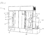
- FIG. 1 shows a filter cleaning system 10 for use in a method in accordance with a preferred embodiment of the present invention.
- the method uses a system including both a dry cleaning section 12 that employs air or other gas to clean the filter and a wet cleaning section 14 that employs water or other liquid, which enhances efficiency and speeds workflow, however it will be understood that the dry cleaning and wet cleaning sections may be installed or used separately or one without the other.
- each of the cleaning sections 12, 14 includes a cleaning chamber in which are placed the filters 16 being cleaned, and which are accessed at the front of the assembly via doors optionally having windows through which an operator can observe the filters and associated fittings during the cleaning process.
- the dry cleaning section provides cleaning of the filters using air or other gas as a fluid, and collection of the dislodged dust from the flow of gas, and also provides a differential pressure test to check cleaning progress and filter integrity, while the wet cleaning section provides cleaning of the filters using water or other liquid as the fluid and filtration of the liquid to remove the dislodged particulate.
- the dry cleaning section 12 includes a cabinet 22 that together with the door 18 provides the accessible cleaning chamber 24 that accommodates the filter 16 to be cleaned, the latter preferably being installed in a generally vertical orientation as shown with the intake "dirty" side down and the outlet “clean” side up so that gravity aids in removing the dislodged particulate.
- the filters are shown partially cutaway to reveal the filter body 26 contained within a metal housing 28, as is typical of DPFs employed for road-going vehicles, for example.
- the intake and outlet pipes 30, 32 are aligned generally vertically and are connected to gas supply conduits in the form of air pipes 34, 36 by adaptors and quick-connect fittings 40 at the ends.
- Air pressure is supplied to connector lines 34, 36 from reservoir tanks 42, 44 at the rear of the cabinet (see FIG. 5 ) via solenoid valves 46, 48; the reservoir pipes 42, 44 are filled with high pressure air from a compressor or other suitable source (not shown), which is released as comparatively high pressure pulses via lines 34, 36 when the solenoid valves are opened.
- the reservoir tanks may suitably be formed of lengths of 3" diameter pipe, for example.
- a second reservoir tank 50 and a solenoid valve 52 are similarly installed on the backside of the wet cleaning section, for use as will be described below.
- solenoid valve 48 when solenoid valve 48 is opened, a pulse of pressurized air is directed through line 36 against the outlet or "clean" side of the filter 16, forcing air through the medium of the filter and dislodging accumulated particulate material from the "dirty” side.
- the particulate material drops through the intake pipe 30 of the filter and through line 34 into a collection bucket 54 having a window 56 that is open to view at the front of the assembly, so that the operator can visually check the amount of material that has been removed.
- one or more pulses in the first direction one or more pulses in the opposite, reverse direction can be applied to the filter by opening the other solenoid valve 46 so that the pulses impinge on the inlet "dirty" side of the filter body to aid in loosening and freeing the deposits.
- a differential pressure measurement may be taken to measure how effectively the DPF has been cleaned.
- a flow of air is supplied from a blower 60 or other suitable source via lines 62 and 34 and passed through the body 26 of the filter at a measured volume and/or pressure.
- Differential pressure is measured across the DPF and compared to reference values for a new filter. Effectiveness may be graded based on comparison of the measured and reference differential pressures, to determine whether the filter has been adequately cleaned for return to service or additional cleaning is needed.
- a comparison can also be used as a test of filter integrity, if the differential is less than that of a new filter.
- Particulate dislodged from the intake "dirty" side of the DPF and collected in bucket 54 may be drawn off through a suction line 64 by a fan 66 at the upper end of a dust collector 68.
- material dislodged from the outlet "clean" side of the filter can be drawn off via suction line 70, that is connected to the upper pulse line 36 at a "T" 72.
- the dust collector thus can also take a suction on either end of the filter; for example, when pulsing the filter on the outlet "clean" end, the dust collector can draw a suction on the dirty end past the viewing port a vice versa.
- the dust collector may include an internal pulse line within the primary filter to facilitate removal of soot/ash from the primary filter.
- the soot and ash fall to the bottom of the dust collector for removal via a bucket or an external vacuum source, as desired.
- the wet cleaning section 14 includes a cabinet 80 enclosing a chamber 82 that holds the filter 16 and is accessible via the door 18 at the front.
- First and second fluid lines 84 and 86 form liquid supply conduits.
- the first line 84 is connected to the outlet pipe 32 on the clean side of the filter using an adaptor and quick-connect coupler 40, and the second line 86 is similarly connected to the inlet pipe on the "dirty" side of the filter.
- Water is supplied to a mixing and recirculation tank 88 from a tap or other source via line 90, and may be mixed with chemical additives to form liquid cleaning solution as desired; tank 88 may incorporate a heater for heating the solution to increase its cleaning effectiveness.
- the solution is pumped to a primary solution tank 92 that is located on the upper part of the assembly above the level of the DPF/DOC that is being cleaned.
- a valve Upon opening a valve, the solution flows from tank 92 down through lines 94 and 84 to fill the volume of the element 26 of the filter with a solid mass or "slug" of liquid.
- Air pressure is then applied to the top of the slug from reservoir 50 (see FIG. 5 ) by opening solenoid valve 52, generating a downward pressure that works in conjunction with gravity to force the liquid solution through the medium of the filter body.
- the liquid flow dislodges the particulate from the filter so that the dislodged material passes down through the intake pipe of the filter and into line 86 along with the liquid that has flowed through the filter.
- the upper surface 96 of the slug 98 may reach the body 26 of the filter so that the pressurized air follows the liquid into the filter medium, depending on the intended cleaning cycle.
- the liquid filtration system may also be used to perform standalone processing of cleaning solution to remove soot, ash and other particulates, particularly if multiple solutions are to be used and it is desirable to keep spent solutions separated for processing; for standalone operations, the system may additionally employ an initial settling tank to allow gravitational removal of heavy solids, one or more filters to remove additional soot and ash and/or chemical treatment to change solution chemistry.
- the liquid solution that has passed through to the "dirty" side of the filter accumulates under pressure in line 100 and tank 102.
- the valves of the system By realigning the valves of the system the liquid solution can consequently be driven in a reverse direction from the dirty side towards the clean side of the filter.
- working the liquid solution back and forth through the medium of the filter with a surging or plunging action is highly effective at removing the deposits.
- An example cleaning cycle of this type is set forth below:
- Cleaning cycle steps 6-15 may be repeated until no more soot and/or ash are observed coming out of the DPF via the viewing chamber. Viewing of the particulate soot/ash and cleaning solution discharged from the filter may be supplemented or replaced using a sensor mechanism that monitors the levels of the material being removed from the filter.
- the System operation may be controlled by a PLC or similar computer system.
- the operator may input the DPF/DOC part number, serial number and/or other date at the beginning of the cleaning cycle.
- the control system may alert the operator of false, warnings and/or operational status using a display or indicators, and may send cleaning data to external computers or databases.
- the dry and wet cleaning sections may have individual controls and be able to operate simultaneously except that it is not possible to share components.
- the dry and wet sections both need to access a shared component, the first one to need it may have use of the shared component while the other side enters a "wait" cycle until the shared component is available for use. Simultaneous operation will then resume and continue.
Landscapes
- Engineering & Computer Science (AREA)
- Chemical & Material Sciences (AREA)
- Combustion & Propulsion (AREA)
- Mechanical Engineering (AREA)
- General Engineering & Computer Science (AREA)
- Chemical Kinetics & Catalysis (AREA)
- Processes For Solid Components From Exhaust (AREA)
- Filtering Of Dispersed Particles In Gases (AREA)
- Cleaning In General (AREA)
- Cleaning By Liquid Or Steam (AREA)
Description
- The present invention relates generally to a method of cleaning a diesel exhaust particulate collectors, such as diesel particulate filters (DPF), diesel oxidation catalysts (DOC), and similar emission control components, and, more particularly, to a method of cleaning that employs fluid pulses or surges applied to ends of a DPF, DOC or other diesel exhaust particulate collector to dislodge and remove accumulated material from the collector.
- Diesel particulate filters and similar emissions components are employed to collect noxious materials from exhaust streams of diesel engines, primarily in the form of particulates comprised mainly of soot. The most common types of diesel particulate filters (DPF) include wall-flow DPFs that are highly efficient in removing particulate, as well as diesel oxidation catalysts (DOC) that tend to be less efficient but operate to reduce the organic component of the collected soot. In the following description and the appended claims such components will be referred to collectively using the terms diesel particulate collector, diesel particulate filter, DPF (or DPF/DOC), whether used with diesel engines or to collect materials from other exhaust streams.
- DPFs feature a filter body formed of ceramic or other filter media capable of withstanding high exhaust temperatures, with a honeycomb structure of elongate tubes opening alternately to the intake (dirty) and outlet (clean) sides of the exhaust. The filter body is commonly housed within a shell formed of metal or other material and having inlet and outlet connections; in the case of DPFs used with trucks or busses, the intake end of the shell may connect to the exhaust pipe from the engine so as to lead the raw exhaust gas to the "dirty" side of the filter, while the other end of the shell may have a connection leading from the "clean" side of the filter to the atmosphere via an exhaust stack or similar pipe.
- Due to the nature of their operation DPFs rapidly collect and remove particulates from the exhaust stream, commonly in the form of soot and/or ash but sometimes including particles of metallic material. Due to the high pressures and temperatures of the exhaust systems the particulate material is driven hard against the "dirty" side of the filter, where it eventually accumulates and builds up to the point of restricting the flow and reducing efficiency of the engine. DPFs consequently require periodic cleaning to remove the accumulated matter, since due to their very substantial cost they are not normally considered routinely disposable items.
- Since much of the accumulated material tends to adhere tenaciously to the filter medium, effectively cleaning the filters tends to be quite challenging. Jets of high pressure air have commonly been used, but while reasonably effective in many instances the ability of air to remove the particulates is ultimately limited by the compressibility of the fluid and other factors. Water and other liquids have also been used, but the resistance offered by the filter medium designed for use with a gas rather than liquids presents difficulties of their own when trying to force the fluid through from the clean side and establish an adequate pressure and flow to remove the deposits from the dirty side of the medium. However, the permissible pressure differential is limited, due to the potential for fracturing and rupturing the cellular walls and destroying the filter, at very significant cost. Therefore, although air/gas and water/liquid approaches have been employed to clean DPFs, the efficacy of available systems has heretofore been significantly limited by the above and other factors.
-
DE 10 2008 038 026 A1 discloses a system for cleaning a DPF in which a rinsing fluid is flowed through the filter in alternate directions, with the optional addition of pressurised air into the rinsing fluid. A hot air drying step is then performed.US 2010/307339 A1 discloses a method of regenerating a DPF by directing pulses of air at a first filter face followed by redirecting the pulses at a second, opposite filter face.FR 2 794 992 A1GB 2 472 104 - According to a first aspect of the present invention there is provided a method for cleaning a diesel particulate filter having a dirty side directed towards an incoming flow of exhaust and a clean side directed towards an outgoing flow of exhaust, said method comprising the steps of:
wet cleaning said filter employing a liquid that removes particulate from said filter, the step of wet cleaning said filter comprising: - mounting said clean side of said filter in fluid communication with a first liquid supply conduit;
- mounting said dirty side of said filter in fluid communication with a second liquid supply conduit;
- surging a slug of said liquid through said filter alternatingly from said clean and dirty sides of said filter through said first and second liquid supply conduits and wherein the step of surging said slug of said liquid through said filter comprises applying a gas at alternating pressures to opposite sides of said slug of said liquid through said first and second liquid supply conduits and wherein a pressure mechanism alternately applies pressure in opposite directions to at least one end of said slug of liquid; and
- driving the liquid in a reverse direction from the dirty side to the clean side of said filter with significantly less pressure relative to the pressure in the direction from the clean side to the dirty side of the filter so as to slowly move the liquid back to the outlet side of the filter.
- The present invention addresses the problems cited above, and provides a method for effective cleaning of diesel particulate filters, including diesel oxidation catalysts and similar particulate collection and/or reactions components. The invention provides a method including a wet cleaning system using water or a water solution or other liquid that may be used with a dry cleaning system using air or other gas. The dry cleaning apparatus and the wet cleaning apparatus may be combined as cooperating sections of a single assembly or may be installed or employed as separate systems.
- The method includes a wet cleaning system that drives a solid mass or slug of the cleaning liquid through the DPF/DOC to remove the particulate matter. The water may be driven by air pressure applied above/behind a surface of the mass or by other mechanisms, such as by a ram for example. The mass or slug of liquid is surged or plunged back and forth through the medium of the filter to help dislodge and remove the particulates. The dislodged material may be removed from the cleaning liquid by a liquid particulate filter.
- The method may include a dry cleaning system which may employ pulses of air directed towards opposite "clean" and "dirty" sides of the DPF/DOC with the dislodged particulate being drawn off to a dust collector or otherwise disposed of. The dry cleaning system may include a cabinet in which the filter is housed for cleaning, and the discharge removed from the dirty side of the filter may pass through a viewing area for visual check by the operator. The dry cleaning system may also include a pressure differential check to determine cleaning efficacy.
- These and other features and advantages of the invention will be more fully appreciated from a reading of the following detailed description with reference to the accompanying drawings.
-
-
FIG. 1 is a front perspective view of a combination dry/gas and wet/liquid filter cleaning apparatus used in a method in accordance with the present invention, with first and second DPFs connected for cleaning in the dry and wet sides of the system being visible through window in doors at the front of the apparatus; -
FIG. 2 is a front perspective view of the system ofFIG. 1 with the front panels and doors removed, showing the two DPFs and the cleaning systems of the present invention that are connected thereto in greater detail; -
FIG. 3 is an enlarged perspective view of the filter undergoing cleaning on the wet/liquid side of the system ofFIGS. 1-3 , the filter being shown partly cut away to show the filter body and other internal aspects of the DPF; -
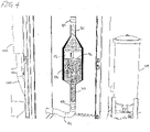
FIG. 4 is a second enlarged perspective view of the installed DPF ofFIG. 3 , showing the manner in which a mass of water is surged back and forth through the body of the filter; and -
FIG. 5 is a rear perspective view of the filter cleaning system ofFIG. 1 . -
FIG. 1 shows afilter cleaning system 10 for use in a method in accordance with a preferred embodiment of the present invention. The method uses a system including both adry cleaning section 12 that employs air or other gas to clean the filter and awet cleaning section 14 that employs water or other liquid, which enhances efficiency and speeds workflow, however it will be understood that the dry cleaning and wet cleaning sections may be installed or used separately or one without the other. - As can be seen with further reference to
FIG. 1 , each of thecleaning sections filters 16 being cleaned, and which are accessed at the front of the assembly via doors optionally having windows through which an operator can observe the filters and associated fittings during the cleaning process. - As will be described in greater detail below, the dry cleaning section provides cleaning of the filters using air or other gas as a fluid, and collection of the dislodged dust from the flow of gas, and also provides a differential pressure test to check cleaning progress and filter integrity, while the wet cleaning section provides cleaning of the filters using water or other liquid as the fluid and filtration of the liquid to remove the dislodged particulate.
- As can be seen in
FIG. 2 , thedry cleaning section 12 includes acabinet 22 that together with thedoor 18 provides theaccessible cleaning chamber 24 that accommodates thefilter 16 to be cleaned, the latter preferably being installed in a generally vertical orientation as shown with the intake "dirty" side down and the outlet "clean" side up so that gravity aids in removing the dislodged particulate. For purposes of illustration the filters are shown partially cutaway to reveal thefilter body 26 contained within ametal housing 28, as is typical of DPFs employed for road-going vehicles, for example. The intake andoutlet pipes air pipes 34, 36 by adaptors and quick-connect fittings 40 at the ends. - Air pressure is supplied to
connector lines 34, 36 fromreservoir tanks FIG. 5 ) viasolenoid valves reservoir pipes lines 34, 36 when the solenoid valves are opened. The reservoir tanks may suitably be formed of lengths of 3" diameter pipe, for example. Asecond reservoir tank 50 and asolenoid valve 52 are similarly installed on the backside of the wet cleaning section, for use as will be described below. - Therefore, when
solenoid valve 48 is opened, a pulse of pressurized air is directed throughline 36 against the outlet or "clean" side of thefilter 16, forcing air through the medium of the filter and dislodging accumulated particulate material from the "dirty" side. The particulate material drops through theintake pipe 30 of the filter and through line 34 into acollection bucket 54 having awindow 56 that is open to view at the front of the assembly, so that the operator can visually check the amount of material that has been removed. After one or more pulses in the first direction, one or more pulses in the opposite, reverse direction can be applied to the filter by opening theother solenoid valve 46 so that the pulses impinge on the inlet "dirty" side of the filter body to aid in loosening and freeing the deposits. - One example sequence for cleaning of a filer using the dry cleaning section is as follows, it being understood that the examples provided by way of illustration rather than limitation and that these steps may vary depending on embodiment and circumstances:
- a. 3-5 pulses of air from the clean end. Pressure, duration and number of pulses (1 or more) are variable as needed.
- b. 1-2 pulses of air from the dirty end. Again, pressure, duration and number of pulses are variable as needed.
- c. During pulses from the dirty end (inlet), air that passes through and out of the DPF's clean end (outlet) may be monitored by a sensor that measures the particulate.
- d. During pulses from the clean end (outlet), soot and ash are blown out of the filter. This may be observed by an operator to assess cleanliness and/or integrity of the filer; optionally a particulate sensor may monitor the soot and ash blown out of the filter in place of or in additional to the viewing area.
- e. Steps a-d are repeated as necessary until no more soot or ash is observed/measured in step d.
- Following or during the cleaning sequence, a differential pressure measurement may be taken to measure how effectively the DPF has been cleaned. A flow of air is supplied from a
blower 60 or other suitable source via lines 62 and 34 and passed through thebody 26 of the filter at a measured volume and/or pressure. Differential pressure is measured across the DPF and compared to reference values for a new filter. Effectiveness may be graded based on comparison of the measured and reference differential pressures, to determine whether the filter has been adequately cleaned for return to service or additional cleaning is needed. A comparison can also be used as a test of filter integrity, if the differential is less than that of a new filter. - Particulate dislodged from the intake "dirty" side of the DPF and collected in
bucket 54 may be drawn off through asuction line 64 by afan 66 at the upper end of a dust collector 68. Similarly, material dislodged from the outlet "clean" side of the filter can be drawn off viasuction line 70, that is connected to theupper pulse line 36 at a "T" 72. The dust collector thus can also take a suction on either end of the filter; for example, when pulsing the filter on the outlet "clean" end, the dust collector can draw a suction on the dirty end past the viewing port a vice versa. - The dust collector may include an internal pulse line within the primary filter to facilitate removal of soot/ash from the primary filter. The soot and ash fall to the bottom of the dust collector for removal via a bucket or an external vacuum source, as desired.
- Similar to the dry cleaning section described above, the
wet cleaning section 14 includes acabinet 80 enclosing achamber 82 that holds thefilter 16 and is accessible via thedoor 18 at the front. First andsecond fluid lines first line 84 is connected to theoutlet pipe 32 on the clean side of the filter using an adaptor and quick-connect coupler 40, and thesecond line 86 is similarly connected to the inlet pipe on the "dirty" side of the filter. Water is supplied to a mixing andrecirculation tank 88 from a tap or other source vialine 90, and may be mixed with chemical additives to form liquid cleaning solution as desired;tank 88 may incorporate a heater for heating the solution to increase its cleaning effectiveness. - From
tank 88 the solution is pumped to aprimary solution tank 92 that is located on the upper part of the assembly above the level of the DPF/DOC that is being cleaned. Upon opening a valve, the solution flows fromtank 92 down throughlines element 26 of the filter with a solid mass or "slug" of liquid. Air pressure is then applied to the top of the slug from reservoir 50 (seeFIG. 5 ) by openingsolenoid valve 52, generating a downward pressure that works in conjunction with gravity to force the liquid solution through the medium of the filter body. As this is done, the liquid flow dislodges the particulate from the filter so that the dislodged material passes down through the intake pipe of the filter and intoline 86 along with the liquid that has flowed through the filter. With continued flow, theupper surface 96 of theslug 98 may reach thebody 26 of the filter so that the pressurized air follows the liquid into the filter medium, depending on the intended cleaning cycle. - From
line 86 the liquid solution flows generally horizontally and then vertically through upwardlyleading line 100 to apressurized storage tank 102 at its upper end. The pressurized tank holds a volume of the fluid with a pressurized blanket of air or other gas at the top. Particulate material dislodged from the filter and carried throughline 86 is drawn off and extracted by liquidparticulate filter 104, with a clean discharge being circulated back totank 88. The particulate material collected byfilter 104 is in turn discharged to asediment collection tank 106 for subsequent removal. Any liquid spilling inchamber 82 is similarly collected intank 106 via adrain opening 108 and asluice bucket 110. The liquid filtration system may also be used to perform standalone processing of cleaning solution to remove soot, ash and other particulates, particularly if multiple solutions are to be used and it is desirable to keep spent solutions separated for processing; for standalone operations, the system may additionally employ an initial settling tank to allow gravitational removal of heavy solids, one or more filters to remove additional soot and ash and/or chemical treatment to change solution chemistry. - As noted above, the liquid solution that has passed through to the "dirty" side of the filter accumulates under pressure in
line 100 andtank 102. By realigning the valves of the system the liquid solution can consequently be driven in a reverse direction from the dirty side towards the clean side of the filter. In particular, it has been found that working the liquid solution back and forth through the medium of the filter with a surging or plunging action is highly effective at removing the deposits. An example cleaning cycle of this type is set forth below: - 1. DPF/DOC is installed into wet cleaning chamber.
- 2. A pressure test is performed to check for leaks.
- 3. If filter was not previously cleaned on dry side, a pre-cleaning differential pressure measurement may be taken.
- 4. DPF/DOC is filled with heated cleaning solution. Extra solution is loaded into conduit system that extends beyond the inlet and outlet of the DPF.
- 5. Solution is "surged" back and forth through the filter as described below.
- 6. Pressurized air is applied on top of the cleaning solution from the plumbing at the outlet (clean end) of the DPF being cleaned. Air pressure and duration of application are variable. At the same time, a vent valve is opened on the plumbing at the inlet (dirty end) of the DPF. Due to the pressurized air applied, the cleaning solution moves through the DPF/DOC from the outlet towards the inlet, removing soot and/or ash. In other embodiments the slug may be surged back-and-forth by an alternate mechanism, such as by one or more hydraulic rams/pistons acting directly or indirectly on the liquid of the slug.
- 7. Soot and ash that are removed from the DPF settle into a trap or "Tee" in the plumbing on the inlet side of the filter.
- 8. Air pressure and vent valves are turned off.
- 9. Pressurized air is applied on top of the cleaning solution from the plumbing at the inlet (dirty end) of the DPF being cleaned. Air pressure and duration of application are variable. At the same time, a vent valve is opened on the plumbing at the outlet (clean end) of the DPF. Due to the pressurized air applied, the cleaning solution moves through the DPF/DOC in this direction is significantly less than the pressure to be used in the cleaning direction, preferably so as to slowly move fluid back to the outlet side of the filter for another cleaning cycle without shoving ash and soot back into the DPF.
- 10. When cleaning solution reaches a predetermined level as measured in the plumbing attached to the outlet side of the DPF, the air pressure and vent valves are closed.
- 11. Cleaning cycle steps 6-10 may be repeated as necessary. Number of repetitions May be varied as needed. After completion of X number of cycles of steps 6-10 the following steps may optionally be performed.
- 12. Pressurized air is applied on top of the cleaning solution from the plumbing at the outlet (clean end) of the DPF being cleaned. Air pressure and duration of application are variable.
- 13. A drain valve is opened below the trap or "Tee" described in step 7 for a brief period of time. Soot, ash and solution are removed and sent to the filtration system through a tube or enclosure that allows viewing of the soot/ash/solution mixture. The DPF/DOC is not completely drained of cleaning solution.
- 14. Additional solution is loaded into the plumbing from the outlet end of the DPF to make up for the volume removed in
step 14. These amounts may or may not be equal. - Cleaning cycle steps 6-15 may be repeated until no more soot and/or ash are observed coming out of the DPF via the viewing chamber. Viewing of the particulate soot/ash and cleaning solution discharged from the filter may be supplemented or replaced using a sensor mechanism that monitors the levels of the material being removed from the filter.
- 15. Drying of the DPF/DOC
- a. After the cleaning cycle is completed all remaining soot, ash and cleaning solution are drained from the DPF/DOC and connected plumbing.
- b. Pressurized air is applied to the DPF/DOC via plumbing attached to the outlet of the filter. Air pressure and volume of air are variable.
- c. A valve in the plumbing attached to the inlet of the DPF is opened to the wet cleaning chamber.
- d. A vapor capture system may be attached to the wet cleaning chamber. (examples include a spin-down charcoal filer, or similar device)
- e. Pressurized air blows cleaning solution out of the filter and into the wet side cleaning cabinet. Steam and water droplets condense and fall out in the larger cleaning chamber. Reduced moisture air is vented from the cleaning chamber via the attached vapor capture system. Dry air from the vapor capture system can be additionally filtered if needed.
- f. Clean, dry air discharged from the system can be HEPA filtered into the operator space or vented outside as desired.
- 16. After the DPF/DOC is dry, a final differential air pressure measurement may be performed.
- System operation may be controlled by a PLC or similar computer system. The operator may input the DPF/DOC part number, serial number and/or other date at the beginning of the cleaning cycle. The control system may alert the operator of false, warnings and/or operational status using a display or indicators, and may send cleaning data to external computers or databases.
- The dry and wet cleaning sections may have individual controls and be able to operate simultaneously except that it is not possible to share components. When the dry and wet sections both need to access a shared component, the first one to need it may have use of the shared component while the other side enters a "wait" cycle until the shared component is available for use. Simultaneous operation will then resume and continue.
- It will be understood that the scope of the appended claims should not be limited by particular embodiments set forth herein, but should be construed in a manner consistent with the specification as a whole.
Claims (6)
- A method for cleaning a diesel particulate filter (16) having a dirty side directed towards an incoming flow of exhaust and a clean side directed towards an outgoing flow of exhaust, said method comprising the steps of:
wet cleaning said filter (16) employing a liquid that removes particulate from said filter (16), the step of wet cleaning said filter (16) comprising:mounting said clean side of said filter (16) in fluid communication with a first liquid supply conduit (84);mounting said dirty side of said filter (16) in fluid communication with a second liquid supply conduit (86);surging a slug (98) of said liquid through said filter (16) alternatingly from said clean and dirty sides of said filter (16) through said first and second liquid supply conduits (84, 86) and wherein the step of surging said slug (98) of said liquid through said filter (16) comprises applying a gas at alternating pressures to opposite sides of said slug (98) of said liquid through said first and second liquid supply conduits (84, 86) and wherein a pressure mechanism alternately applies pressure in opposite directions to at least one end of said slug (98) of liquid; anddriving the liquid in a reverse direction from the dirty side to the clean side of said filter (16) with significantly less pressure relative to the pressure in the direction from the clean side to the dirty side of the filter (16) so as to slowly move the liquid back to the outlet side of the filter (16). - The method of claim 1, comprising the steps of:
dry cleaning said filter (16) by employing a gas to clean particulate from said filter (16), the step of dry cleaning said filter (16) comprising:mounting said clean side of said filter (16) in fluid communication with a first gas supply conduit (36);mounting said dirty side of said filter (16) in fluid communication with a second gas supply conduit (34); andalternatingly applying pressurized pulses of said gas against said clean and dirty sides of said filter (16) through said first and second gas supply conduits (36, 34). - The method of claim 2, wherein the step of alternatingly applying pulses of said gas against said clean and dirty sides of said filter (16) comprises:
alternatingly supplying a compressed gas from a source to said first and second gas supply conduits (36, 34). - The method of claim 1, wherein the step of surging said slug (98) of said liquid through said filter (16) comprises:
operating at least one hydraulic ram to alternatingly apply pressure to said slug (98) of said liquid in opposite directions through said first and second liquid supply conduits. - The method of claim 1, wherein one end of the slug (98) comprising an upper surface (96) reaches the filter (16) so that the pressurized air follows the liquid into the filter (16) from the clean side; and
applying air pressure to the upper surface (96) of the end of the slug (98) to generate a downward pressure to force the liquid through the filter (16) from the clean side to the dirty side and the liquid flowing through the second supply conduit (86) to a pressurized storage tank (102) to hold a volume of the liquid with a pressurized blanket of gas at a top surface of the other end of the slug (98). - The method of claim 2, further comprising:
measuring a pressure differential of said gas between said dirty and clean sides of said filter (16) to assess a status of said filter (16).
Applications Claiming Priority (2)
| Application Number | Priority Date | Filing Date | Title |
|---|---|---|---|
| US201562283952P | 2015-09-15 | 2015-09-15 | |
| PCT/US2016/000075 WO2017048315A1 (en) | 2015-09-15 | 2016-09-15 | Apparatus and method for cleaning diesel particulate filters |
Publications (2)
| Publication Number | Publication Date |
|---|---|
| EP3350426A1 EP3350426A1 (en) | 2018-07-25 |
| EP3350426B1 true EP3350426B1 (en) | 2023-01-04 |
Family
ID=57121486
Family Applications (1)
| Application Number | Title | Priority Date | Filing Date |
|---|---|---|---|
| EP16778913.0A Active EP3350426B1 (en) | 2015-09-15 | 2016-09-15 | Apparatus and method for cleaning diesel particulate filters |
Country Status (7)
| Country | Link |
|---|---|
| US (1) | US11293318B2 (en) |
| EP (1) | EP3350426B1 (en) |
| JP (1) | JP2018535346A (en) |
| KR (1) | KR20180102536A (en) |
| CN (1) | CN108350779A (en) |
| CA (1) | CA2997613A1 (en) |
| WO (1) | WO2017048315A1 (en) |
Families Citing this family (21)
| Publication number | Priority date | Publication date | Assignee | Title |
|---|---|---|---|---|
| JP6458263B2 (en) * | 2017-03-28 | 2019-01-30 | 朱雀プラスチック株式会社 | Cleaning device for exhaust gas purification unit |
| BG67125B1 (en) * | 2017-06-08 | 2020-08-17 | Саани Исметов Денкчиев | Apparatus and method for cleaning of diesel particulate filters and catalysts |
| JP6381086B1 (en) * | 2017-07-20 | 2018-08-29 | 日本油化工業株式会社 | Cleaning method of collection filter |
| CN108661795A (en) * | 2018-08-08 | 2018-10-16 | 山西百达电子科技有限公司 | A kind of cleaning device of diesel vehicle preprocessor |
| KR102082599B1 (en) * | 2019-01-22 | 2020-04-23 | 고건혁 | A Burning Apparatus for Diesel Particulate Filter and A Cleaning Apparatus using the same |
| CN111561373B (en) * | 2019-02-14 | 2023-01-03 | 康明斯有限公司 | System and method for cleaning particulate filters |
| JP6661815B1 (en) * | 2019-05-09 | 2020-03-11 | 日野リトラックス株式会社 | Filter drying system |
| IN201941034035A (en) * | 2019-08-23 | 2020-02-28 | ||
| CN111894701A (en) * | 2019-10-14 | 2020-11-06 | 灵智燎原(北京)节能环保技术研究院 | Diesel engine DPF pulsating flow cleaning machine |
| WO2021172610A1 (en) * | 2020-02-25 | 2021-09-02 | 고건혁 | Burning device for smoke-reducing apparatus and cleaning device using same |
| JP7471863B2 (en) * | 2020-02-28 | 2024-04-22 | 東京濾器株式会社 | Method for cleaning an oxidation catalyst device for a diesel vehicle |
| CN111330363B (en) * | 2020-03-13 | 2021-08-24 | 苏州德中创恒软件科技有限公司 | Vehicle DPF washs regeneration facility |
| KR102393894B1 (en) * | 2020-03-30 | 2022-05-02 | 고민정 | Vehicle exhaust gas collection and smoke reduction device cleaning device |
| DE102020205719A1 (en) * | 2020-05-06 | 2021-11-11 | Robert Bosch Gesellschaft mit beschränkter Haftung | Method for operating an internal combustion engine with a secondary air system |
| JP6765111B1 (en) * | 2020-06-16 | 2020-10-07 | 有限会社シージーエム | PM removal unit cleaning device and PM removal unit cleaning method |
| DE102020133470B4 (en) * | 2020-12-15 | 2023-12-21 | Mack Gmbh | Cleaning device and method for cleaning a filter arrangement |
| KR102659327B1 (en) * | 2021-04-28 | 2024-04-19 | 서덕술 | washing device for DPF of diesel vehicle |
| CN113250790A (en) * | 2021-06-18 | 2021-08-13 | 浙江银轮智能装备有限公司 | Linkage type double-valve mechanism, particle filter cleaning device and equipment |
| US12209771B1 (en) * | 2021-11-29 | 2025-01-28 | Amazon Technologies, Inc. | Air filtration system for datacenter or other building |
| WO2024257070A1 (en) * | 2024-07-28 | 2024-12-19 | Khalilimehr Farzad | Fully automatic cleaning and testing system for catalysts and filters for reuse |
| KR20250155491A (en) | 2025-10-13 | 2025-10-30 | 구교선 | Self-sealing toner filling system for recycled cartridges and its operating method |
Family Cites Families (32)
| Publication number | Priority date | Publication date | Assignee | Title |
|---|---|---|---|---|
| US4535588A (en) | 1979-06-12 | 1985-08-20 | Nippon Soken, Inc. | Carbon particulates cleaning device for diesel engine |
| JPS6170114A (en) | 1984-09-12 | 1986-04-10 | Nissan Motor Co Ltd | Processing device of exhaust fine particle in internal-combustion engine |
| US4573317A (en) | 1985-03-11 | 1986-03-04 | General Motors Corporation | Diesel exhaust cleaner and regeneration burner system with indexing particulate trap |
| JPH06117218A (en) * | 1992-10-01 | 1994-04-26 | Matsushita Electric Ind Co Ltd | Filter regeneration device for internal combustion engine |
| JP3035128B2 (en) * | 1993-08-09 | 2000-04-17 | 三菱重工業株式会社 | Dust remover |
| US5410977A (en) | 1994-04-08 | 1995-05-02 | Webb; William B. | Rudderless sailboat |
| US5860381A (en) | 1996-01-26 | 1999-01-19 | Fernandini; Alberto Alvarez-Calderon | Variable draft tandem appendages for yachts |
| US6596174B1 (en) * | 1998-09-11 | 2003-07-22 | Alexander C. Marcus | Diesel fuel cleaning and re-circulation system |
| FR2794992B1 (en) * | 1999-06-17 | 2003-04-04 | Peugeot Citroen Automobiles Sa | METHOD AND DEVICE FOR CLEANING A PARTICLE FILTER AND METHOD FOR TREATING EFFLUENTS PRODUCED DURING CLEANING |
| FR2823253B1 (en) | 2001-04-06 | 2003-08-15 | Saint Gobain Ct Recherches | FILTERING BODY FOR FILTERING PARTICLES CONTAINED IN THE EXHAUST GASES OF AN INTERNAL COMBUSTION ENGINE |
| FR2838981B1 (en) * | 2002-04-30 | 2004-07-30 | Faurecia Sys Echappement | METHOD FOR CLEANING THE UPSTREAM FACE OF A PARTICLE FILTER |
| JP4007085B2 (en) | 2002-06-13 | 2007-11-14 | 株式会社デンソー | Exhaust gas purification device for internal combustion engine |
| JP3918649B2 (en) | 2002-06-14 | 2007-05-23 | 株式会社デンソー | Exhaust gas purification device for internal combustion engine |
| JP3922107B2 (en) | 2002-06-14 | 2007-05-30 | 株式会社デンソー | Exhaust gas purification device for internal combustion engine |
| CN100436251C (en) | 2002-09-20 | 2008-11-26 | 梁富泉 | Multiple driving gliding submarine |
| EP1651512A4 (en) | 2003-07-31 | 2009-05-06 | Solar Sailor Pty Ltd | Unmanned ocean vehicle |
| US7410530B2 (en) * | 2005-03-04 | 2008-08-12 | Donaldson Company, Inc. | Apparatus for cleaning exhaust aftertreatment devices and methods |
| JP2007192055A (en) * | 2006-01-17 | 2007-08-02 | Toyota Motor Corp | Exhaust gas purification device and exhaust gas purification method |
| EP2111279A2 (en) * | 2007-01-30 | 2009-10-28 | Donaldson Company, Inc. | Apparatus for cleaning exhaust aftertreatment devices and methods |
| BE1017587A3 (en) | 2007-04-27 | 2009-01-13 | Erik Craps | Sailboat, has solid body pivotally mounted to keel, where keel and mast share horizontal and transverse axes and are linked during rotation one-way coupling so that keel rotates independent of mast in direction of tilt |
| US7582141B2 (en) | 2007-05-31 | 2009-09-01 | International Truck Intellectual Property Company, Llc | Diesel particulate filter pulse cleaner flow director system and method |
| US20090000479A1 (en) | 2007-06-28 | 2009-01-01 | Cleaire Advanced Emission Controls, Llc | Apparatus and method for delivering a fluid to a diesel particulate filter |
| US8206492B2 (en) | 2007-08-29 | 2012-06-26 | Waldo Cole L | Method and apparatus for cleaning diesel particulate filters and for diagnosing damage thereto |
| DE102008038026A1 (en) * | 2008-08-16 | 2010-02-18 | Daimler Ag | Method for cleaning particle filter of vehicle, involves removing particle filter from vehicle, where exhaust gas flow direction of particle filter runs from inlet end to outlet end of particle filter |
| US8241403B2 (en) * | 2009-06-08 | 2012-08-14 | Catalytic Solutions, Inc. | Apparatus and method for regenerating a carbon filter |
| GB2472104B (en) * | 2009-07-25 | 2011-09-07 | Eminox Ltd | Cleaning a vehicle exhaust filter |
| JP5087100B2 (en) * | 2010-03-26 | 2012-11-28 | ヤンマー株式会社 | Cleaning method and cleaning apparatus for particulate matter removing filter |
| EP2542327B1 (en) * | 2010-04-03 | 2016-10-12 | KIPP, Jens-Werner | Method for cleaning filters |
| WO2012061880A1 (en) * | 2010-11-11 | 2012-05-18 | Electrolux Home Products Pty Limited | Self cleaning filter arrangement |
| IT1403687B1 (en) * | 2011-02-07 | 2013-10-31 | Rizzitano | APPARATUS AND METHOD FOR THE REGENERATION OF USED PARTICULATE FILTERS. |
| WO2014032050A1 (en) * | 2012-08-24 | 2014-02-27 | Cummins Ip, Inc. | Exhaust component cleaning and requalification process |
| US11187122B2 (en) * | 2016-11-08 | 2021-11-30 | EcoClean Advantage, LLC | Diesel particulate filter cleaning machine with filter cleaning time prediction |
-
2016
- 2016-09-15 US US15/330,410 patent/US11293318B2/en active Active
- 2016-09-15 CA CA2997613A patent/CA2997613A1/en not_active Abandoned
- 2016-09-15 KR KR1020187010188A patent/KR20180102536A/en not_active Withdrawn
- 2016-09-15 CN CN201680053452.3A patent/CN108350779A/en active Pending
- 2016-09-15 EP EP16778913.0A patent/EP3350426B1/en active Active
- 2016-09-15 JP JP2018515099A patent/JP2018535346A/en active Pending
- 2016-09-15 WO PCT/US2016/000075 patent/WO2017048315A1/en not_active Ceased
Also Published As
| Publication number | Publication date |
|---|---|
| WO2017048315A1 (en) | 2017-03-23 |
| JP2018535346A (en) | 2018-11-29 |
| KR20180102536A (en) | 2018-09-17 |
| EP3350426A1 (en) | 2018-07-25 |
| CN108350779A (en) | 2018-07-31 |
| US11293318B2 (en) | 2022-04-05 |
| WO2017048315A9 (en) | 2017-04-20 |
| CA2997613A1 (en) | 2017-03-23 |
| US20170211440A1 (en) | 2017-07-27 |
Similar Documents
| Publication | Publication Date | Title |
|---|---|---|
| US11293318B2 (en) | Diesel exhaust particulate collectors | |
| DE4313132C2 (en) | Process for cleaning particle filters and particle filters | |
| US11187122B2 (en) | Diesel particulate filter cleaning machine with filter cleaning time prediction | |
| CA2921031C (en) | Fluid treatment system | |
| KR102063982B1 (en) | Apparatus for cleaning diesel particuate filter of vehicle | |
| US2685347A (en) | Method of cleaning lubricant chambers and the lubricant therein | |
| US20150000701A1 (en) | Method and apparatus for cleaning diesel particulate filters | |
| JP2010501331A (en) | Apparatus and method for cleaning piping and piping systems | |
| DE102008038026A1 (en) | Method for cleaning particle filter of vehicle, involves removing particle filter from vehicle, where exhaust gas flow direction of particle filter runs from inlet end to outlet end of particle filter | |
| US4783958A (en) | Exhaust gas processing device and method | |
| CN217041686U (en) | Backwashing filter capable of rapidly sampling and detecting | |
| CN104324535B (en) | There is filter plant and filter method, the back-washing method of eddy flow backwash function | |
| CN106103925A (en) | For cleaning the apparatus and method of filter, especially particulate filter | |
| CN104040124B (en) | Method and apparatus for clean particulate filter | |
| BG112519A (en) | Apparatus and method for cleaning of diesel particulate filters and catalysts | |
| CN207169275U (en) | A kind of housing filter cartridge cleaning device | |
| US20200197989A1 (en) | Flush Station | |
| FI112780B (en) | Process for purifying a filter element contained in a filter space and the filter applying the method | |
| CN119972613A (en) | Spray washing equipment and process for engine cylinder head | |
| CN116747610A (en) | Movable paper filter element cleaner and cleaning method thereof | |
| DE10118864C2 (en) | Method and device for cleaning the at least one soot filter body of an exhaust gas cleaning device | |
| US7707839B2 (en) | Declogging device and declogging method | |
| CN223353988U (en) | Grinding fluid filtering device for surface grinder machining | |
| CN220345330U (en) | Chemical waste gas safety filtering treatment device with self-cleaning function | |
| CN222159888U (en) | Multistage aeration tank |
Legal Events
| Date | Code | Title | Description |
|---|---|---|---|
| STAA | Information on the status of an ep patent application or granted ep patent |
Free format text: STATUS: UNKNOWN |
|
| STAA | Information on the status of an ep patent application or granted ep patent |
Free format text: STATUS: THE INTERNATIONAL PUBLICATION HAS BEEN MADE |
|
| PUAI | Public reference made under article 153(3) epc to a published international application that has entered the european phase |
Free format text: ORIGINAL CODE: 0009012 |
|
| STAA | Information on the status of an ep patent application or granted ep patent |
Free format text: STATUS: REQUEST FOR EXAMINATION WAS MADE |
|
| 17P | Request for examination filed |
Effective date: 20180405 |
|
| AK | Designated contracting states |
Kind code of ref document: A1 Designated state(s): AL AT BE BG CH CY CZ DE DK EE ES FI FR GB GR HR HU IE IS IT LI LT LU LV MC MK MT NL NO PL PT RO RS SE SI SK SM TR |
|
| AX | Request for extension of the european patent |
Extension state: BA ME |
|
| DAV | Request for validation of the european patent (deleted) | ||
| DAX | Request for extension of the european patent (deleted) | ||
| STAA | Information on the status of an ep patent application or granted ep patent |
Free format text: STATUS: EXAMINATION IS IN PROGRESS |
|
| 17Q | First examination report despatched |
Effective date: 20200224 |
|
| GRAP | Despatch of communication of intention to grant a patent |
Free format text: ORIGINAL CODE: EPIDOSNIGR1 |
|
| STAA | Information on the status of an ep patent application or granted ep patent |
Free format text: STATUS: GRANT OF PATENT IS INTENDED |
|
| INTG | Intention to grant announced |
Effective date: 20220811 |
|
| GRAS | Grant fee paid |
Free format text: ORIGINAL CODE: EPIDOSNIGR3 |
|
| GRAA | (expected) grant |
Free format text: ORIGINAL CODE: 0009210 |
|
| STAA | Information on the status of an ep patent application or granted ep patent |
Free format text: STATUS: THE PATENT HAS BEEN GRANTED |
|
| AK | Designated contracting states |
Kind code of ref document: B1 Designated state(s): AL AT BE BG CH CY CZ DE DK EE ES FI FR GB GR HR HU IE IS IT LI LT LU LV MC MK MT NL NO PL PT RO RS SE SI SK SM TR |
|
| REG | Reference to a national code |
Ref country code: GB Ref legal event code: FG4D |
|
| REG | Reference to a national code |
Ref country code: CH Ref legal event code: EP |
|
| REG | Reference to a national code |
Ref country code: AT Ref legal event code: REF Ref document number: 1542071 Country of ref document: AT Kind code of ref document: T Effective date: 20230115 |
|
| REG | Reference to a national code |
Ref country code: DE Ref legal event code: R096 Ref document number: 602016077260 Country of ref document: DE |
|
| REG | Reference to a national code |
Ref country code: IE Ref legal event code: FG4D |
|
| REG | Reference to a national code |
Ref country code: LT Ref legal event code: MG9D |
|
| REG | Reference to a national code |
Ref country code: NL Ref legal event code: MP Effective date: 20230104 |
|
| REG | Reference to a national code |
Ref country code: AT Ref legal event code: MK05 Ref document number: 1542071 Country of ref document: AT Kind code of ref document: T Effective date: 20230104 |
|
| PG25 | Lapsed in a contracting state [announced via postgrant information from national office to epo] |
Ref country code: NL Free format text: LAPSE BECAUSE OF FAILURE TO SUBMIT A TRANSLATION OF THE DESCRIPTION OR TO PAY THE FEE WITHIN THE PRESCRIBED TIME-LIMIT Effective date: 20230104 |
|
| PG25 | Lapsed in a contracting state [announced via postgrant information from national office to epo] |
Ref country code: RS Free format text: LAPSE BECAUSE OF FAILURE TO SUBMIT A TRANSLATION OF THE DESCRIPTION OR TO PAY THE FEE WITHIN THE PRESCRIBED TIME-LIMIT Effective date: 20230104 Ref country code: PT Free format text: LAPSE BECAUSE OF FAILURE TO SUBMIT A TRANSLATION OF THE DESCRIPTION OR TO PAY THE FEE WITHIN THE PRESCRIBED TIME-LIMIT Effective date: 20230504 Ref country code: NO Free format text: LAPSE BECAUSE OF FAILURE TO SUBMIT A TRANSLATION OF THE DESCRIPTION OR TO PAY THE FEE WITHIN THE PRESCRIBED TIME-LIMIT Effective date: 20230404 Ref country code: LV Free format text: LAPSE BECAUSE OF FAILURE TO SUBMIT A TRANSLATION OF THE DESCRIPTION OR TO PAY THE FEE WITHIN THE PRESCRIBED TIME-LIMIT Effective date: 20230104 Ref country code: LT Free format text: LAPSE BECAUSE OF FAILURE TO SUBMIT A TRANSLATION OF THE DESCRIPTION OR TO PAY THE FEE WITHIN THE PRESCRIBED TIME-LIMIT Effective date: 20230104 Ref country code: HR Free format text: LAPSE BECAUSE OF FAILURE TO SUBMIT A TRANSLATION OF THE DESCRIPTION OR TO PAY THE FEE WITHIN THE PRESCRIBED TIME-LIMIT Effective date: 20230104 Ref country code: ES Free format text: LAPSE BECAUSE OF FAILURE TO SUBMIT A TRANSLATION OF THE DESCRIPTION OR TO PAY THE FEE WITHIN THE PRESCRIBED TIME-LIMIT Effective date: 20230104 Ref country code: AT Free format text: LAPSE BECAUSE OF FAILURE TO SUBMIT A TRANSLATION OF THE DESCRIPTION OR TO PAY THE FEE WITHIN THE PRESCRIBED TIME-LIMIT Effective date: 20230104 |
|
| PG25 | Lapsed in a contracting state [announced via postgrant information from national office to epo] |
Ref country code: SE Free format text: LAPSE BECAUSE OF FAILURE TO SUBMIT A TRANSLATION OF THE DESCRIPTION OR TO PAY THE FEE WITHIN THE PRESCRIBED TIME-LIMIT Effective date: 20230104 Ref country code: PL Free format text: LAPSE BECAUSE OF FAILURE TO SUBMIT A TRANSLATION OF THE DESCRIPTION OR TO PAY THE FEE WITHIN THE PRESCRIBED TIME-LIMIT Effective date: 20230104 Ref country code: IS Free format text: LAPSE BECAUSE OF FAILURE TO SUBMIT A TRANSLATION OF THE DESCRIPTION OR TO PAY THE FEE WITHIN THE PRESCRIBED TIME-LIMIT Effective date: 20230504 Ref country code: GR Free format text: LAPSE BECAUSE OF FAILURE TO SUBMIT A TRANSLATION OF THE DESCRIPTION OR TO PAY THE FEE WITHIN THE PRESCRIBED TIME-LIMIT Effective date: 20230405 Ref country code: FI Free format text: LAPSE BECAUSE OF FAILURE TO SUBMIT A TRANSLATION OF THE DESCRIPTION OR TO PAY THE FEE WITHIN THE PRESCRIBED TIME-LIMIT Effective date: 20230104 |
|
| REG | Reference to a national code |
Ref country code: DE Ref legal event code: R097 Ref document number: 602016077260 Country of ref document: DE |
|
| PG25 | Lapsed in a contracting state [announced via postgrant information from national office to epo] |
Ref country code: SM Free format text: LAPSE BECAUSE OF FAILURE TO SUBMIT A TRANSLATION OF THE DESCRIPTION OR TO PAY THE FEE WITHIN THE PRESCRIBED TIME-LIMIT Effective date: 20230104 Ref country code: RO Free format text: LAPSE BECAUSE OF FAILURE TO SUBMIT A TRANSLATION OF THE DESCRIPTION OR TO PAY THE FEE WITHIN THE PRESCRIBED TIME-LIMIT Effective date: 20230104 Ref country code: EE Free format text: LAPSE BECAUSE OF FAILURE TO SUBMIT A TRANSLATION OF THE DESCRIPTION OR TO PAY THE FEE WITHIN THE PRESCRIBED TIME-LIMIT Effective date: 20230104 Ref country code: DK Free format text: LAPSE BECAUSE OF FAILURE TO SUBMIT A TRANSLATION OF THE DESCRIPTION OR TO PAY THE FEE WITHIN THE PRESCRIBED TIME-LIMIT Effective date: 20230104 Ref country code: CZ Free format text: LAPSE BECAUSE OF FAILURE TO SUBMIT A TRANSLATION OF THE DESCRIPTION OR TO PAY THE FEE WITHIN THE PRESCRIBED TIME-LIMIT Effective date: 20230104 |
|
| PLBE | No opposition filed within time limit |
Free format text: ORIGINAL CODE: 0009261 |
|
| STAA | Information on the status of an ep patent application or granted ep patent |
Free format text: STATUS: NO OPPOSITION FILED WITHIN TIME LIMIT |
|
| PG25 | Lapsed in a contracting state [announced via postgrant information from national office to epo] |
Ref country code: SK Free format text: LAPSE BECAUSE OF FAILURE TO SUBMIT A TRANSLATION OF THE DESCRIPTION OR TO PAY THE FEE WITHIN THE PRESCRIBED TIME-LIMIT Effective date: 20230104 |
|
| 26N | No opposition filed |
Effective date: 20231005 |
|
| PG25 | Lapsed in a contracting state [announced via postgrant information from national office to epo] |
Ref country code: SI Free format text: LAPSE BECAUSE OF FAILURE TO SUBMIT A TRANSLATION OF THE DESCRIPTION OR TO PAY THE FEE WITHIN THE PRESCRIBED TIME-LIMIT Effective date: 20230104 |
|
| REG | Reference to a national code |
Ref country code: CH Ref legal event code: PL |
|
| PG25 | Lapsed in a contracting state [announced via postgrant information from national office to epo] |
Ref country code: LU Free format text: LAPSE BECAUSE OF NON-PAYMENT OF DUE FEES Effective date: 20230915 |
|
| REG | Reference to a national code |
Ref country code: BE Ref legal event code: MM Effective date: 20230930 |
|
| PG25 | Lapsed in a contracting state [announced via postgrant information from national office to epo] |
Ref country code: LU Free format text: LAPSE BECAUSE OF NON-PAYMENT OF DUE FEES Effective date: 20230915 Ref country code: IT Free format text: LAPSE BECAUSE OF FAILURE TO SUBMIT A TRANSLATION OF THE DESCRIPTION OR TO PAY THE FEE WITHIN THE PRESCRIBED TIME-LIMIT Effective date: 20230104 Ref country code: MC Free format text: LAPSE BECAUSE OF FAILURE TO SUBMIT A TRANSLATION OF THE DESCRIPTION OR TO PAY THE FEE WITHIN THE PRESCRIBED TIME-LIMIT Effective date: 20230104 |
|
| REG | Reference to a national code |
Ref country code: IE Ref legal event code: MM4A |
|
| PG25 | Lapsed in a contracting state [announced via postgrant information from national office to epo] |
Ref country code: IE Free format text: LAPSE BECAUSE OF NON-PAYMENT OF DUE FEES Effective date: 20230915 |
|
| PG25 | Lapsed in a contracting state [announced via postgrant information from national office to epo] |
Ref country code: CH Free format text: LAPSE BECAUSE OF NON-PAYMENT OF DUE FEES Effective date: 20230930 |
|
| PG25 | Lapsed in a contracting state [announced via postgrant information from national office to epo] |
Ref country code: IE Free format text: LAPSE BECAUSE OF NON-PAYMENT OF DUE FEES Effective date: 20230915 Ref country code: CH Free format text: LAPSE BECAUSE OF NON-PAYMENT OF DUE FEES Effective date: 20230930 |
|
| PG25 | Lapsed in a contracting state [announced via postgrant information from national office to epo] |
Ref country code: BE Free format text: LAPSE BECAUSE OF NON-PAYMENT OF DUE FEES Effective date: 20230930 |
|
| PGFP | Annual fee paid to national office [announced via postgrant information from national office to epo] |
Ref country code: DE Payment date: 20240702 Year of fee payment: 9 |
|
| PGFP | Annual fee paid to national office [announced via postgrant information from national office to epo] |
Ref country code: GB Payment date: 20240701 Year of fee payment: 9 |
|
| PGFP | Annual fee paid to national office [announced via postgrant information from national office to epo] |
Ref country code: FR Payment date: 20240702 Year of fee payment: 9 |
|
| PG25 | Lapsed in a contracting state [announced via postgrant information from national office to epo] |
Ref country code: BG Free format text: LAPSE BECAUSE OF FAILURE TO SUBMIT A TRANSLATION OF THE DESCRIPTION OR TO PAY THE FEE WITHIN THE PRESCRIBED TIME-LIMIT Effective date: 20230104 |
|
| PG25 | Lapsed in a contracting state [announced via postgrant information from national office to epo] |
Ref country code: BG Free format text: LAPSE BECAUSE OF FAILURE TO SUBMIT A TRANSLATION OF THE DESCRIPTION OR TO PAY THE FEE WITHIN THE PRESCRIBED TIME-LIMIT Effective date: 20230104 |
|
| PG25 | Lapsed in a contracting state [announced via postgrant information from national office to epo] |
Ref country code: CY Free format text: LAPSE BECAUSE OF FAILURE TO SUBMIT A TRANSLATION OF THE DESCRIPTION OR TO PAY THE FEE WITHIN THE PRESCRIBED TIME-LIMIT; INVALID AB INITIO Effective date: 20160915 |
|
| PG25 | Lapsed in a contracting state [announced via postgrant information from national office to epo] |
Ref country code: HU Free format text: LAPSE BECAUSE OF FAILURE TO SUBMIT A TRANSLATION OF THE DESCRIPTION OR TO PAY THE FEE WITHIN THE PRESCRIBED TIME-LIMIT; INVALID AB INITIO Effective date: 20160915 |
|
| PG25 | Lapsed in a contracting state [announced via postgrant information from national office to epo] |
Ref country code: TR Free format text: LAPSE BECAUSE OF FAILURE TO SUBMIT A TRANSLATION OF THE DESCRIPTION OR TO PAY THE FEE WITHIN THE PRESCRIBED TIME-LIMIT Effective date: 20230104 |