EP3350367B1 - Atomiseur de liquide comportant un element piezoelectrique et fer a repasser comportant un tel atomiseur - Google Patents
Atomiseur de liquide comportant un element piezoelectrique et fer a repasser comportant un tel atomiseur Download PDFInfo
- Publication number
- EP3350367B1 EP3350367B1 EP16777721.8A EP16777721A EP3350367B1 EP 3350367 B1 EP3350367 B1 EP 3350367B1 EP 16777721 A EP16777721 A EP 16777721A EP 3350367 B1 EP3350367 B1 EP 3350367B1
- Authority
- EP
- European Patent Office
- Prior art keywords
- liquid
- atomiser
- horn
- cavity
- atomizer
- Prior art date
- Legal status (The legal status is an assumption and is not a legal conclusion. Google has not performed a legal analysis and makes no representation as to the accuracy of the status listed.)
- Active
Links
- XEEYBQQBJWHFJM-UHFFFAOYSA-N Iron Chemical compound [Fe] XEEYBQQBJWHFJM-UHFFFAOYSA-N 0.000 title claims description 54
- 239000007788 liquid Substances 0.000 title claims description 39
- 229910052742 iron Inorganic materials 0.000 title claims description 26
- 239000012528 membrane Substances 0.000 claims description 46
- XLYOFNOQVPJJNP-UHFFFAOYSA-N water Substances O XLYOFNOQVPJJNP-UHFFFAOYSA-N 0.000 claims description 29
- 238000001228 spectrum Methods 0.000 claims description 7
- 239000007921 spray Substances 0.000 claims description 7
- 238000009792 diffusion process Methods 0.000 claims description 6
- 238000006073 displacement reaction Methods 0.000 claims description 6
- 239000003242 anti bacterial agent Substances 0.000 claims description 3
- 230000003115 biocidal effect Effects 0.000 claims description 3
- 238000001914 filtration Methods 0.000 claims description 2
- 238000009688 liquid atomisation Methods 0.000 claims description 2
- 239000003595 mist Substances 0.000 claims description 2
- 239000000919 ceramic Substances 0.000 description 8
- 238000000889 atomisation Methods 0.000 description 4
- 239000011248 coating agent Substances 0.000 description 4
- 238000000576 coating method Methods 0.000 description 4
- 239000004744 fabric Substances 0.000 description 4
- 238000010438 heat treatment Methods 0.000 description 4
- 238000010409 ironing Methods 0.000 description 4
- 238000005507 spraying Methods 0.000 description 4
- 239000000443 aerosol Substances 0.000 description 3
- 230000003321 amplification Effects 0.000 description 3
- 238000003199 nucleic acid amplification method Methods 0.000 description 3
- PXHVJJICTQNCMI-UHFFFAOYSA-N Nickel Chemical compound [Ni] PXHVJJICTQNCMI-UHFFFAOYSA-N 0.000 description 2
- BQCADISMDOOEFD-UHFFFAOYSA-N Silver Chemical compound [Ag] BQCADISMDOOEFD-UHFFFAOYSA-N 0.000 description 2
- 238000009826 distribution Methods 0.000 description 2
- 230000005284 excitation Effects 0.000 description 2
- 229910001220 stainless steel Inorganic materials 0.000 description 2
- 239000010935 stainless steel Substances 0.000 description 2
- 241000195493 Cryptophyta Species 0.000 description 1
- 235000019738 Limestone Nutrition 0.000 description 1
- 238000004026 adhesive bonding Methods 0.000 description 1
- 230000000181 anti-adherent effect Effects 0.000 description 1
- 239000003911 antiadherent Substances 0.000 description 1
- 238000005219 brazing Methods 0.000 description 1
- 238000004140 cleaning Methods 0.000 description 1
- 238000010276 construction Methods 0.000 description 1
- 238000001816 cooling Methods 0.000 description 1
- 238000002788 crimping Methods 0.000 description 1
- 230000008021 deposition Effects 0.000 description 1
- 239000006185 dispersion Substances 0.000 description 1
- 238000001035 drying Methods 0.000 description 1
- 239000000835 fiber Substances 0.000 description 1
- PCHJSUWPFVWCPO-UHFFFAOYSA-N gold Chemical compound [Au] PCHJSUWPFVWCPO-UHFFFAOYSA-N 0.000 description 1
- 229910052737 gold Inorganic materials 0.000 description 1
- 239000010931 gold Substances 0.000 description 1
- 238000009499 grossing Methods 0.000 description 1
- 239000012535 impurity Substances 0.000 description 1
- 239000006028 limestone Substances 0.000 description 1
- 238000012986 modification Methods 0.000 description 1
- 230000004048 modification Effects 0.000 description 1
- 229910052759 nickel Inorganic materials 0.000 description 1
- 239000002245 particle Substances 0.000 description 1
- 230000000284 resting effect Effects 0.000 description 1
- 239000000523 sample Substances 0.000 description 1
- 238000003756 stirring Methods 0.000 description 1
- 238000006467 substitution reaction Methods 0.000 description 1
- 239000010409 thin film Substances 0.000 description 1
- 238000009834 vaporization Methods 0.000 description 1
- 230000008016 vaporization Effects 0.000 description 1
- 238000005406 washing Methods 0.000 description 1
- 238000003466 welding Methods 0.000 description 1
Images

Classifications
-
- B—PERFORMING OPERATIONS; TRANSPORTING
- B05—SPRAYING OR ATOMISING IN GENERAL; APPLYING FLUENT MATERIALS TO SURFACES, IN GENERAL
- B05B—SPRAYING APPARATUS; ATOMISING APPARATUS; NOZZLES
- B05B17/00—Apparatus for spraying or atomising liquids or other fluent materials, not covered by the preceding groups
- B05B17/04—Apparatus for spraying or atomising liquids or other fluent materials, not covered by the preceding groups operating with special methods
- B05B17/06—Apparatus for spraying or atomising liquids or other fluent materials, not covered by the preceding groups operating with special methods using ultrasonic or other kinds of vibrations
- B05B17/0607—Apparatus for spraying or atomising liquids or other fluent materials, not covered by the preceding groups operating with special methods using ultrasonic or other kinds of vibrations generated by electrical means, e.g. piezoelectric transducers
- B05B17/0638—Apparatus for spraying or atomising liquids or other fluent materials, not covered by the preceding groups operating with special methods using ultrasonic or other kinds of vibrations generated by electrical means, e.g. piezoelectric transducers spray being produced by discharging the liquid or other fluent material through a plate comprising a plurality of orifices
- B05B17/0646—Vibrating plates, i.e. plates being directly subjected to the vibrations, e.g. having a piezoelectric transducer attached thereto
-
- B—PERFORMING OPERATIONS; TRANSPORTING
- B05—SPRAYING OR ATOMISING IN GENERAL; APPLYING FLUENT MATERIALS TO SURFACES, IN GENERAL
- B05B—SPRAYING APPARATUS; ATOMISING APPARATUS; NOZZLES
- B05B15/00—Details of spraying plant or spraying apparatus not otherwise provided for; Accessories
- B05B15/50—Arrangements for cleaning; Arrangements for preventing deposits, drying-out or blockage; Arrangements for detecting improper discharge caused by the presence of foreign matter
- B05B15/58—Arrangements for cleaning; Arrangements for preventing deposits, drying-out or blockage; Arrangements for detecting improper discharge caused by the presence of foreign matter preventing deposits, drying-out or blockage by recirculating the fluid to be sprayed from upstream of the discharge opening back to the supplying means
-
- B—PERFORMING OPERATIONS; TRANSPORTING
- B05—SPRAYING OR ATOMISING IN GENERAL; APPLYING FLUENT MATERIALS TO SURFACES, IN GENERAL
- B05B—SPRAYING APPARATUS; ATOMISING APPARATUS; NOZZLES
- B05B17/00—Apparatus for spraying or atomising liquids or other fluent materials, not covered by the preceding groups
- B05B17/04—Apparatus for spraying or atomising liquids or other fluent materials, not covered by the preceding groups operating with special methods
- B05B17/06—Apparatus for spraying or atomising liquids or other fluent materials, not covered by the preceding groups operating with special methods using ultrasonic or other kinds of vibrations
- B05B17/0607—Apparatus for spraying or atomising liquids or other fluent materials, not covered by the preceding groups operating with special methods using ultrasonic or other kinds of vibrations generated by electrical means, e.g. piezoelectric transducers
- B05B17/0623—Apparatus for spraying or atomising liquids or other fluent materials, not covered by the preceding groups operating with special methods using ultrasonic or other kinds of vibrations generated by electrical means, e.g. piezoelectric transducers coupled with a vibrating horn
- B05B17/063—Apparatus for spraying or atomising liquids or other fluent materials, not covered by the preceding groups operating with special methods using ultrasonic or other kinds of vibrations generated by electrical means, e.g. piezoelectric transducers coupled with a vibrating horn having an internal channel for supplying the liquid or other fluent material
-
- B—PERFORMING OPERATIONS; TRANSPORTING
- B05—SPRAYING OR ATOMISING IN GENERAL; APPLYING FLUENT MATERIALS TO SURFACES, IN GENERAL
- B05B—SPRAYING APPARATUS; ATOMISING APPARATUS; NOZZLES
- B05B17/00—Apparatus for spraying or atomising liquids or other fluent materials, not covered by the preceding groups
- B05B17/04—Apparatus for spraying or atomising liquids or other fluent materials, not covered by the preceding groups operating with special methods
- B05B17/06—Apparatus for spraying or atomising liquids or other fluent materials, not covered by the preceding groups operating with special methods using ultrasonic or other kinds of vibrations
- B05B17/0607—Apparatus for spraying or atomising liquids or other fluent materials, not covered by the preceding groups operating with special methods using ultrasonic or other kinds of vibrations generated by electrical means, e.g. piezoelectric transducers
- B05B17/0653—Details
- B05B17/0676—Feeding means
-
- B—PERFORMING OPERATIONS; TRANSPORTING
- B05—SPRAYING OR ATOMISING IN GENERAL; APPLYING FLUENT MATERIALS TO SURFACES, IN GENERAL
- B05B—SPRAYING APPARATUS; ATOMISING APPARATUS; NOZZLES
- B05B17/00—Apparatus for spraying or atomising liquids or other fluent materials, not covered by the preceding groups
- B05B17/04—Apparatus for spraying or atomising liquids or other fluent materials, not covered by the preceding groups operating with special methods
- B05B17/06—Apparatus for spraying or atomising liquids or other fluent materials, not covered by the preceding groups operating with special methods using ultrasonic or other kinds of vibrations
- B05B17/0607—Apparatus for spraying or atomising liquids or other fluent materials, not covered by the preceding groups operating with special methods using ultrasonic or other kinds of vibrations generated by electrical means, e.g. piezoelectric transducers
- B05B17/0653—Details
- B05B17/0669—Excitation frequencies
Definitions
- the present invention relates to a liquid atomizer comprising a piezoelectric element fixed on a vibratory displacement amplification tube comprising a cavity containing the liquid to be atomized and relates more particularly to an atomizer in which the horn is mechanically and acoustically coupled to a membrane micro-perforated closing one side of the cavity.
- an ultrasonic liquid atomizer comprising a piezoelectric element fixed on a vibratory amplification amplifying tube comprising an end coupled to a micro-perforated membrane closing a cavity formed inside the horn containing the liquid to be atomized
- Such an atomizer has the advantage of vibrating in a longitudinal mode and to allow the instantaneous spraying of a quantity of liquid very accurately with drops of regular size.
- the limited height of water above the membrane and the presence of an airtight tank make it possible to avoid the problems of dripping through the membrane when the atomizer is at a standstill.
- an object of the present invention is to provide a liquid atomizer, comprising a vibratory displacement amplifying amplification tube comprising a cavity containing the liquid to be atomized closed by a micro-perforated membrane, which can operate for a long time, or even continuously, and which has no problem of dripping when the atomization is stopped.
- Another object of the present invention is to provide an iron equipped with such an atomizer.
- the subject of the invention is a liquid atomiser comprising a piezoelectric element fixed on a vibratory displacement amplifying probe comprising a cavity containing the liquid to be atomized, the trunk comprising a first part receiving the piezoelectric element and a second part , distinct from the first part, mechanically and acoustically coupled to a micro-perforated membrane closing one side of the cavity, characterized in that the cavity is fed with liquid from a reservoir with a flow rate greater than the spray rate of the atomizer in operation and in that the horn comprises at least one outlet hole connecting the cavity to a bypass duct to the tank.
- the exit hole will be sufficiently distant from the first part receiving the piezoelectric element not to disturb too much the vibratory operation of the atomizer.
- the exit hole will also be advantageously sufficiently far from the micro-perforated membrane so that the flow of liquid through the exit hole does not come to disturb the operation of the micro-perforated membrane.
- Such an atomizer has the advantage of having a micro-perforated membrane fixed on a part of the vibrating horn in a longitudinal mode, which makes it possible to produce an aerosol with very little dispersion in the diameter of the micro-droplets.
- the cavity is fed with liquid from the reservoir by means of a pump operating continuously during the liquid atomization phases by the atomizer.
- Such continuous operation of the pump has the advantage of cleaning the upper surface of the membrane and preventing the deposition of undesirable particles.
- the pump also operates, punctually or continuously, outside phases atomization of liquid by the atomizer.
- the piezoelectric atomiser vibrates in a longitudinal mode in the range 50 kHz to 200 kHz.
- the horn has a sectional variation between the first portion supporting the piezoelectric element and the second portion coupled to the micro-perforated membrane.
- Such a section variation has the advantage of amplifying the longitudinal ultrasonic waves emitted by the piezoelectric element and makes it possible to have a level of amplitude such that the scale that can be deposited on the micro-perforated membrane is eliminated.
- the micro-perforated membrane is attached to a longitudinal end of the horn.
- the trunk has an axis of revolution and comprises at least two exit holes arranged symmetrically with respect to the axis of revolution, the outlet holes communicating with an evacuation chamber connected to the duct. diversion to the reservoir.
- Such an arrangement of the exit holes has the advantage of not disturbing the vibratory mode of the horn and makes it possible to obtain a vibration mode of the horn adapted to obtain the spraying of micro-droplets having a mono median diameter. -dispersed centered in a range that can be between 20 microns and 100 microns.
- the micro-perforated membrane is coupled to one end of a cylindrical body of the horn, the outlet holes being formed on the cylindrical body.
- the micro-perforated membrane is made of electro-formed stainless steel and is covered with a non-stick coating.
- non-stick coating is meant a coating on which a drop of liquid makes a contact angle greater than 90 °.
- Such an anti-adherent coating makes it possible to limit the adhesion of scale on the membrane.
- the micro-perforated membrane has holes having a diameter of less than 40 ⁇ m, the holes being distant from each other by more than 400 ⁇ m. Such a construction makes it possible to reduce the problem of dripping through the membrane.
- the outlet hole or holes are remote from the micro-perforated membrane with a height h of less than 10 mm and preferably of the order of 2 mm.
- Such a feature makes it possible to eliminate the problems of dripping and to obtain optimized operation of the atomizer during the start and stop phases.
- the outlet hole or holes have a diameter greater than or equal to 2 mm.
- the atomizer comprises a feed chamber communicating on the one hand with the cavity and on the other hand with a water inlet duct connected to the pump, the feed chamber having an air inlet.
- the air inlet orifice comprises a filtration device preventing the intrusion of a foreign body into the feed chamber.
- the cavity is fed with liquid from the reservoir by a feed circuit comprising a water filter and a device for dispensing an antibiotic product, such as colloidal silver.
- a feed circuit comprising a water filter and a device for dispensing an antibiotic product, such as colloidal silver.
- the invention also relates to an iron having a heating soleplate surmounted by a housing enclosing a reservoir and comprising a liquid atomizer as previously described.
- the atomizer is carried by the box of the iron and moistens a treatment zone located outside the sole.
- the atomizer sprays water with a flow rate of between 6 and 20 g / min and preferably of the order of 9 g / min.
- the atomizer diffuses a mist of micro-droplets whose median mono-dispersed diameter is between 30 microns and 60 microns.
- Such a characteristic makes it possible to obtain a fog which at the same time does not fly off too much and does not make water stains on the clothes to be ironed.
- the atomizer has a diffusion spectrum adapted to humidify a treatment zone extending along the two edges of a front tip of the sole.
- Such a feature allows, with a single atomizer, to moisten the laundry located on both sides of the front tip of the sole.
- the holes of the micro-perforated membrane are distributed in a V-shape.
- Such a characteristic makes it possible to obtain a diffusion spectrum of the micro-droplets conforming to the V shape of the front tip of the sole.
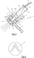
- the figure 1 represents a steam iron 1 comprising, in known manner, a sole 2 in thermal contact with a heating body, not shown in the figures, containing an electrical resistance of a power of the order of 1600 W and having a vaporization chamber dimensioned to produce a flow rate of steam of the order of 20 gr / min to be distributed through holes in the sole 2, the temperature of the sole 2 being controlled by a thermostat whose temperature of setpoint can be changed by the user using a knob 3.
- the sole 2 is surmounted by a plastic housing 4 incorporating a handle 40 and comprising a heel 41 on which the iron can stand vertically during the inactive ironing phases, the heel 41 being advantageously equipped with a connector , not visible in the figures, allowing the electrical connection of the iron to a charging base.
- the housing 4 encloses a tank 5 of water, shown diagrammatically in dashed lines, and has a tapered front end supporting a spraying device consisting of an atomizer 6 of ultrasonic liquid producing micro-droplets, of sizes predominantly between 30 ⁇ m and 60 ⁇ m in diameter, for moistening a spray zone located in front of the front tip of the sole 2.
- a spraying device consisting of an atomizer 6 of ultrasonic liquid producing micro-droplets, of sizes predominantly between 30 ⁇ m and 60 ⁇ m in diameter, for moistening a spray zone located in front of the front tip of the sole 2.
- the iron 1 also comprises a scraper element 10 extending outside the soleplate 2 heating, at a distance of about 3 mm from the edge of the soleplate 2, allowing to penetrate mechanically the droplets of liquid inside the laundry to be ironed before the sole 2 heating reaches the spray area.
- scraper element 10 is written in more detail in the patent application FR1158318 filed by the plaintiff.
- the atomizer 6 comprises a cylindrical envelope 60 hollow plastic including a lateral protrusion 61 provided with a bore adapted to receive a fixing screw of the atomizer 6 on the casing 4 of the iron, the casing 60 having a receiving chamber 62 in which is disposed a electromechanical aerosol generator 7 operating in the range 50 kHz to 200 kHz.
- the receiving chamber 62 has an open lower end 62A and an opposite end having an opening 62B communicating with a supply chamber 63 located above the receiving chamber 62 when the iron is resting on its sole 2, the chamber supply 63 having an upper end closed by a cover 64 and comprising a lateral orifice 63A forming a vent ensuring an atmospheric pressure of the feed chamber 63, this vent 63A is advantageously equipped with a filter, not shown in the figures, preventing the intrusion of a foreign body into the feed chamber 63.
- the feed chamber 63 receives water from the tank 5 by a feed circuit comprising a water inlet pipe 50 passing through the lid 64, the inlet pipe 50 being connected to a pump 51, shown schematically on the figure 2 , whose operation is controlled by means of a push button 11 arranged in front of the handle 40.
- the feed circuit also comprises a water filter and an antibiotic diffuser device, such as colloidal silver. , not shown in the figures.
- the aerosol generator 7 comprises a piezoelectric ceramic 8 bonded to a vibratory displacement amplifying tube 9 traversed by a cavity 90 comprising the liquid to be atomized, the cavity 90 extending along an axis of revolution R of the horn 9 and being closed at one end by a micro-perforated membrane 91 of small thickness, between 20 and 200 ⁇ m, mechanically and acoustically coupled to the horn 9.
- the piezoelectric ceramic 8 is in known manner electrically powered by means of a power supply circuit, not shown in the figures, providing an alternating current across the ceramic piezoelectric 8, the latter being powered electrically only when the push button 11 is actuated by the user.
- the trunk 9 has a shoulder 92 on which the piezoelectric ceramic 8 is glued and comprises a cylindrical body 93 of smaller section at the longitudinal end of which the micro-perforated membrane 91 is mechanically and acoustically fixed, for example by gluing. brazing, crimping or welding.
- the trunk 9 has a diameter of about 16 mm at the shoulder 92 supporting the piezoelectric ceramic 8 and a diameter of about 8 mm at the height of the cylindrical body 93.
- the micro-perforated membrane 91 has a thickness of 50 microns and comprises a network of holes with a diameter of less than 40 microns, the holes being spaced apart from each other by more than 400 microns.
- the micro-perforated membrane 91 is advantageously made of electro-formed nickel or electro-formed stainless steel, preferably coated with gold, to combat the adhesion of limestone.
- the micro-perforated membrane 91 has seventy holes 35 ⁇ m in diameter, preferentially distributed in a V-shape as shown in FIG. figure 4 , such a distribution of holes to obtain, with a single atomizer, a V-shaped micro-droplet diffusion spectrum which is adapted to match the shape of the front tip of the sole 2.
- the cavity 90 has, opposite the micro-perforated membrane 91, an open end communicating with the feed chamber 63 via the opening 62B so that the water present in the feed chamber 63 flows into the cavity 90.
- the flow rate of the pump 51 supplying the cavity 90 is greater than the flow rate of the atomizer 6 during operation, and the horn 9 preferably comprises two exit holes 94 aligned along a horizontal axis and arranged symmetrically with respect to the axis of revolution R of the horn 9, each outlet hole 94 opening into an annular discharge chamber 65, surrounding the cylindrical body 93 of the horn 9, which communicates with a bypass duct 66 to the tank 5.
- the atomizer 6 has a water spraying rate of the order of 9 g / min to optimally moisten the clothes to be ironed and the pump 51 supplies water to the chamber of water. supply 63 with a flow rate of the order of 12 gr / min.
- the outlet holes 94 have a diameter greater than or equal to 2 mm to allow a good flow of the excess water sent by the pump 51 to the branch conduit 66, the outlet holes 94 being distant from the micro-perforated membrane 91 with a height h of the order of 2 mm to permanently have a thin film of water covering the micro-perforated membrane 91.
- micro-droplets thus emitted by the atomizer 6 are deposited on the surface of the ironing fabric and then impregnate the fabric being pressed by the wiper element 10 during the advancement of the iron, which causes a humidification and therefore a relaxation of the fibers of the fabric, before the sole 2 hot iron does not come dry the fabric, to obtain a perfect smoothing.
- Such an atomizer 6 thus has the advantage of being able to operate continuously until the water in the tank 5 is exhausted, the circulation of the excess water sent by the pump 51 having the advantage of stirring and renewing the water situated above the micro-perforated membrane 91, which makes it possible to evacuate any impurities that may stagnate on the micro-perforated membrane 91 and to improve the cooling of the micro-perforated membrane 91 during use extended atomizer 6.
- Such an atomizer also has the advantage of consuming very little energy and producing micro-droplets of very regular size, which makes it particularly suitable for use on a low-consumption iron and especially on an iron. wireless.
- Such an atomizer comprising a vibrating horn in a longitudinal mode has the advantage of having a diffusion spectrum of the micro-droplets which depends directly on the distribution of the holes on the microperforated membrane. It is thus possible to obtain a V-shaped microdroplet diffusion spectrum which is adapted to match the shape of the front tip of the sole so as to moisten the laundry on the front and sides of the front tip of the sole. the sole without projecting micro-droplets on the iron case.
- the horn may have only one exit hole communicating with the bypass duct.
- the exit holes may have a passage section of non-circular shape and be of smaller size.
- the pump may also operate continuously or episodically, when the piezoelectric ceramic is not electrically powered, that is to say outside the atomization phases of liquid by the atomizer.
- the pump can operate as soon as the iron is electrically connected to the electrical network.
- Such an embodiment variant has the advantage of ensuring a continuous washing of the upper surface of the membrane by the circulation of water.
Landscapes
- Special Spraying Apparatus (AREA)
- Nozzles (AREA)
Description
- La présente invention se rapporte à un atomiseur de liquide comportant un élément piézoélectrique fixé sur une trompe amplificatrice de déplacements vibratoires comprenant une cavité contenant le liquide à atomiser et se rapporte plus particulièrement à un atomiseur dans lequel la trompe est couplée mécaniquement et acoustiquement à une membrane micro-perforée venant fermer un côté de la cavité.
- Il est connu, de la demande de brevet
FR2908329 - Un tel atomiseur présente l'avantage de vibrer selon un mode longitudinal et de permettre la pulvérisation instantanée d'une quantité de liquide de manière très précise avec des gouttes de taille régulière. De plus, la hauteur d'eau limitée au-dessus de la membrane et la présence d'un réservoir étanche à l'air permettent d'éviter les problèmes de gouttage au travers de la membrane lorsque atomiseur est à l'arrêt.
- Cependant, un tel atomiseur de liquide présente l'inconvénient de ne pas pouvoir fonctionner pendant un temps important du fait de la capacité limitée du réservoir d'eau. Or, il n'est pas possible d'augmenter simplement le volume du réservoir au-dessus de la membrane micro-perforée car une telle augmentation de volume entrainerait une augmentation de la hauteur de colonne d'eau au-dessus de la membrane qui générerait un écoulement de goutte d'eau non souhaité au travers de la membrane lorsque l'atomiseur est arrêté. D'autres exemples sont divulgués par les documents
FR2987564 WO2016/150822 (Art. 54(3) CBE). - Aussi, un but de la présente invention est de proposer un atomiseur de liquide, comportant une trompe amplificatrice de déplacements vibratoires comprenant une cavité contenant le liquide à atomiser fermée par une membrane micro-perforée, qui puisse fonctionner pendant un temps important, voire en continu, et qui ne présente pas de problème de gouttage lorsque l'atomisation est arrêtée. Un autre but de la présente invention est de proposer un fer à repasser équipé d'un tel atomiseur.
- A cet effet, l'invention a pour objet un atomiseur de liquide comportant un élément piézoélectrique fixé sur une trompe amplificatrice de déplacements vibratoires comprenant une cavité contenant le liquide à atomiser, la trompe comprenant une première partie recevant l'élément piézoélectrique et une deuxième partie, distincte de la première partie, couplée mécaniquement et acoustiquement à une membrane micro-perforée venant fermer un côté de la cavité, caractérisé en ce que la cavité est alimentée avec du liquide en provenance d'un réservoir avec un débit supérieur au débit de pulvérisation de l'atomiseur en fonctionnement et en ce que la trompe comporte au moins un trou de sortie reliant la cavité à un conduit de dérivation vers le réservoir.
- De préférence, le trou de sortie sera suffisamment distant de la première partie recevant l'élément piézoélectrique pour ne pas trop perturber le fonctionnement vibratoire de l'atomiseur. Le trou de sortie sera également avantageusement suffisamment éloigné de la membrane micro-perforée pour que le flux de liquide au travers du trou de sortie ne vienne pas perturber le fonctionnement de la membrane micro-perforée.
- Un tel atomiseur présente l'avantage de posséder une membrane micro-perforée fixée sur une partie de la trompe vibrant selon un mode longitudinal, ce qui permet de produire un aérosol avec très peu de dispersion dans le diamètre des micro-gouttelettes.
- Selon une autre caractéristique de l'invention, la cavité est alimentée avec du liquide en provenance du réservoir au moyen d'une pompe fonctionnant en continu durant les phases d'atomisation de liquide par l'atomiseur.
- Un tel fonctionnement de la pompe en continu présente l'avantage de nettoyer la surface supérieure de la membrane et d'éviter le dépôt de particules indésirables.
- Selon encore une autre caractéristique de l'invention, la pompe fonctionne également, de manière ponctuelle ou en continu, en dehors des phases d'atomisation de liquide par l'atomiseur.
- Selon une autre caractéristique de l'invention, l'atomiseur piézoélectrique vibre suivant un mode longitudinal dans la gamme 50 kHz à 200 kHz.
- Selon une autre caractéristique de l'invention, la trompe présente une variation de section entre la première partie supportant l'élément piézoélectrique et la deuxième partie couplée à la membrane micro-perforée.
- Une telle variation de section présente l'avantage d'amplifier les ondes ultrasonores longitudinales émises par l'élément piézoélectrique et permet d'avoir un niveau d'amplitude tel que le tartre pouvant se déposer sur la membrane micro-perforée est éliminé.
- Selon une autre caractéristique de l'invention, la membrane micro-perforée est fixée à une extrémité longitudinale de la trompe.
- Selon une autre caractéristique de l'invention, la trompe présente un axe de révolution et comporte au moins deux trous de sortie disposés symétriquement par rapport à l'axe de révolution, les trous de sortie communicant avec une chambre d'évacuation reliée au conduit de dérivation vers le réservoir.
- Une telle disposition des trous de sortie présente l'avantage de ne pas trop perturber le mode vibratoire de la trompe et permet l'obtention d'un mode de vibration de la trompe adapté pour obtenir la pulvérisation de micro-gouttelettes présentant un diamètre médian mono-dispersé centré dans une gamme pouvant être comprise entre 20 µm et 100 µm.
- Selon une autre caractéristique de l'invention, la membrane micro-perforée est couplée à une extrémité d'un corps cylindrique de la trompe, les trous de sortie étant ménagés sur le corps cylindrique.
- Selon une autre caractéristique de l'invention, la membrane micro-perforée est en inox électro-formée et est recouverte d'un revêtement anti-adhérent. Par revêtement anti-adhérent, on entend un revêtement sur lequel une goutte de liquide fait un angle de contact supérieur à 90°. Un tel revêtement anti-adhérent permet de limiter l'adhésion du tartre sur la membrane.
- Selon encore une autre caractéristique de l'invention, la membrane micro-perforée comporte des trous présentant un diamètre inférieur à 40 µm, les trous étant distants les uns des autres de plus de 400 µm. Une telle construction permet de réduire le problème de gouttage au travers de la membrane.
- Selon encore une autre caractéristique de l'invention, le ou les trous de sortie sont distants de la membrane micro-perforée d'une hauteur h inférieure à 10 mm et préférentiellement de l'ordre de 2 mm.
- Une telle caractéristique permet de supprimer les problèmes de gouttage et d'obtenir un fonctionnement optimisé de l'atomiseur lors des phases de démarrage et d'arrêt.
- Selon une autre caractéristique de l'invention, le ou les trous de sortie présentent un diamètre supérieur ou égal à 2 mm.
- Selon une autre caractéristique de l'invention, l'atomiseur comporte une chambre d'alimentation communiquant d'une part avec la cavité et d'autre part avec un conduit d'arrivée d'eau relié à la pompe, la chambre d'alimentation comportant un orifice d'entrée d'air.
- Selon une autre caractéristique de l'invention, l'orifice d'entrée d'air comporte un dispositif de filtration empêchant l'intrusion d'un corps étranger dans la chambre d'alimentation.
- Selon encore une autre caractéristique de l'invention, la cavité est alimentée avec du liquide en provenance du réservoir par un circuit d'alimentation comportant un filtre à eau et un dispositif diffuseur d'un produit antibiotique, tel de l'argent colloïdal. Une telle caractéristique permet d'éviter le développement d'algues dans la cavité.
- L'invention concerne également un fer à repasser comportant une semelle chauffante surmontée par un boitier renfermant un réservoir et comprenant un atomiseur de liquide tel que précédemment décrit.
- Selon une autre caractéristique de l'invention, l'atomiseur est porté par le boitier du fer à repasser et permet d'humidifier une zone de traitement située à l'extérieur de la semelle.
- Selon encore une autre caractéristique de l'invention, l'atomiseur pulvérise de l'eau avec un débit compris entre 6 et 20 gr/min et préférentiellement de l'ordre de 9 gr/min.
- Une telle caractéristique permet d'obtenir une humidification performante pour défroisser le linge sans que celle-ci ne soit trop importante pour ne pas générer des difficultés à sécher le linge lors d'un passage de la semelle du fer à repasser.
- Selon encore une autre caractéristique de l'invention, l'atomiseur diffuse un brouillard de micro-gouttelettes dont le diamètre médian mono-dispersé est compris entre 30 µm et 60 µm.
- Une telle caractéristique permet d'obtenir un brouillard qui à la fois ne s'envole pas trop et ne fait pas des taches d'eau sur le linge à repasser.
- Selon encore une autre caractéristique de l'invention, l'atomiseur présente un spectre de diffusion adapté pour humidifier une zone de traitement s'étendant le long des deux bords d'une pointe avant de la semelle.
- Une telle caractéristique permet, avec un seul atomiseur, d'humidifier le linge situé des deux côtés de la pointe avant de la semelle.
- Selon encore une autre caractéristique de l'invention, les trous de la membrane micro-perforée sont répartis selon une forme de V.
- Une telle caractéristique permet d'obtenir un spectre de diffusion des micro-gouttelettes épousant la forme en V de la pointe avant de la semelle.
- On comprendra mieux les buts, aspects et avantages de la présente invention, d'après la description donnée ci-après d'un mode particulier de réalisation de l'invention présenté à titre d'exemple non limitatif, en se référant aux dessins annexés dans lesquels :
- la
figure 1 est une vue en perspective d'un fer à repasser équipé d'un atomiseur de liquide selon un mode particulier de réalisation de l'invention ; - la
figure 2 est une vue de côté de l'appareil de repassage de lafigure 1 illustrant schématiquement le réservoir et la pompe permettant d"alimenter l'atomiseur ; - la
figure 3 est une vue en coupe longitudinale de l'atomiseur équipant le fer à repasser desfigures 1 ; - la
figure 4 est une vue de dessus de la membrane micro-perforée. - Seuls les éléments nécessaires à la compréhension de l'invention ont été représentés. Pour faciliter la lecture des dessins, les mêmes éléments portent les mêmes références d'une figure à l'autre.
- La
figure 1 représente un fer à repasser 1 à vapeur comportant, de manière connue en soi, une semelle 2 au contact thermique d'un corps chauffant, non représenté sur les figures, renfermant une résistance électrique d'une puissance de l'ordre de 1600 W et comportant une chambre de vaporisation dimensionnée pour produire un débit de vapeur de l'ordre de 20 gr/mn destiné à être distribué au travers de trous ménagés dans la semelle 2, la température de la semelle 2 étant contrôlée par un thermostat dont la température de consigne peut être modifiée par l'utilisateur au moyen d'un bouton de réglage 3. - La semelle 2 est surmontée d'un boitier 4 en matière plastique intégrant une poignée 40 de préhension et comprenant un talon 41 sur lequel le fer à repasser peut reposer verticalement lors des phases inactives de repassage, le talon 41 étant avantageusement équipé d'un connecteur, non visible sur les figures, permettant le raccordement électrique du fer à repasser à une base de recharge.
- Conformément à la
figure 2 , le boitier 4 renferme un réservoir 5 d'eau, représenté schématiquement en pointillés, et comporte une extrémité avant effilée supportant un dispositif de pulvérisation constitué par un atomiseur 6 de liquide par ultrasons produisant des micro-gouttelettes, de tailles majoritairement comprises entre 30 µm et 60 µm de diamètre, permettant d'humidifier une zone de pulvérisation située devant la pointe avant de la semelle 2. - De manière préférentielle, le fer à repasser 1 comporte également un élément racleur 10 s'étendant à l'extérieur de la semelle 2 chauffante, à une distance de l'ordre de 3 mm du bord de la semelle 2, permettant de faire pénétrer mécaniquement les gouttelettes de liquide à l'intérieur du linge à repasser avant que la semelle 2 chauffante ne parvienne sur la zone de pulvérisation. Un tel élément racleur 10 est d'écrit plus en détails dans la demande de brevet
FR1158318 - Conformément à la
figure 3 , l'atomiseur 6 comporte une enveloppe cylindrique 60 creuse en matière plastique comprenant un excroissance latérale 61 munie d'un alésage apte à recevoir une vis de fixation de l'atomiseur 6 sur le boitier 4 du fer à repasser, l'enveloppe 60 comportant une chambre de réception 62 dans laquelle est disposé un générateur d'aérosol 7 électromécanique fonctionnant dans la gamme 50 kHz à 200 kHz. - La chambre de réception 62 comporte une extrémité inférieure 62A ouverte et une extrémité opposée comportant une ouverture 62B communiquant avec une chambre d'alimentation 63 située au-dessus de la chambre de réception 62 lorsque le fer à repasser repose sur sa semelle 2, la chambre d'alimentation 63 comportant une extrémité supérieure fermée par un couvercle 64 et comprenant un orifice latéral 63A formant un évent assurant une mise à la pression atmosphérique de la chambre d'alimentation 63, cet évent 63A étant avantageusement équipé d'un filtre, non représenté sur les figures, empêchant l'intrusion d'un corps étranger dans la chambre d'alimentation 63.
- Conformément aux
figures 2 et3 , la chambre d'alimentation 63 reçoit de l'eau en provenance du réservoir 5 par un circuit d'alimentation comprenant un conduit d'arrivé d'eau 50 traversant le couvercle 64, le conduit d'arrivé d'eau 50 étant relié à une pompe 51, représentée schématiquement sur lafigure 2 , dont le fonctionnement est commandé au moyen d'un bouton poussoir 11 disposé devant la poignée 40. De manière préférentielle, le circuit d'alimentation comporte également un filtre à eau et un dispositif diffuseur d'antibiotique, tel que de l'argent colloïdal, non représentés sur les figures. - Comme on peut le voir sur la
figure 3 , le générateur d'aérosol 7 comprend une céramique piézoélectrique 8 collée sur une trompe 9 amplificatrice de déplacements vibratoires traversée par une cavité 90 comprenant le liquide à atomiser, la cavité 90 s'étendant selon un axe de révolution R de la trompe 9 et étant fermée à une extrémité par une membrane micro-perforée 91 de faible épaisseur, comprise entre 20 et 200 µm, couplée mécaniquement et acoustiquement à la trompe 9. - La céramique piézoélectrique 8 est de manière connue en soi alimentée électriquement au moyen d'un circuit d'alimentation électrique, non représenté sur les figures, fournissant un courant alternatif aux bornes de la céramique piézoélectrique 8, cette dernière étant alimentée électriquement uniquement lorsque le bouton poussoir 11 est actionné par l'utilisateur.
- De manière préférentielle, la trompe 9 comporte un épaulement 92 sur lequel la céramique piézoélectrique 8 est collée et comprend un corps cylindrique 93 de plus faible section à l'extrémité longitudinale duquel la membrane micro-perforée 91 est fixée mécaniquement et acoustiquement par exemple par collage, brasage, sertissage ou soudage.
- A titre d'exemple, la trompe 9 présente un diamètre de l'ordre de 16 mm au niveau de l'épaulement 92 supportant la céramique piézoélectrique 8 et un diamètre de l'ordre de 8 mm à hauteur du corps cylindrique 93.
- De manière préférentielle, la membrane micro-perforée 91 présente une épaisseur de 50 µm et comporte un réseau de trous de diamètre inférieur à 40 µm, les trous étant distants les uns des autres de plus de 400 µm. La membrane micro-perforée 91 est avantageusement réalisée en Nickel électro-formé ou en inox électro-formé, préférentiellement revêtu d'or, pour lutter contre l'adhésion du calcaire.
- A titre d'exemple, la membrane micro-perforée 91 présente soixante-dix trous de 35 µm de diamètre, préférentiellement répartis selon une forme de V comme cela est représenté sur la
figure 4 , une telle répartition des trous permettant d'obtenir, avec un seul atomiseur, un spectre de diffusion des micro-gouttelettes en forme de V qui est adapté pour épouser la forme de la pointe avant de la semelle 2. - La cavité 90 présente, à l'opposé de la membrane micro-perforée 91, une extrémité ouverte communiquant avec la chambre d'alimentation 63 par l'intermédiaire de l'ouverture 62B de sorte que l'eau présente dans la chambre d'alimentation 63 s'écoule dans la cavité 90.
- Plus particulièrement selon l'invention, le débit de la pompe 51 alimentant la cavité 90 est supérieure au débit de l'atomiseur 6 en fonctionnement et la trompe 9 comporte préférentiellement deux trous de sortie 94 alignés selon un axe horizontal et disposés symétriquement par rapport à l'axe de révolution R de la trompe 9, chaque trou de sortie 94 débouchant dans une chambre d'évacuation 65 annulaire, entourant le corps cylindrique 93 de la trompe 9, qui communique avec un conduit de dérivation 66 vers le réservoir 5.
- A titre d'exemple, l'atomiseur 6 présente un débit de pulvérisation d'eau de l'ordre de 9 gr/min pour humidifier de manière optimale le linge à repasser et la pompe 51 fournit de l'eau à la chambre d'alimentation 63 avec un débit de l'ordre de 12 gr/min.
- De manière préférentielle, les trous de sortie 94 présentent un diamètre supérieur ou égal à 2 mm pour permettre un bon écoulement de l'excédent d'eau envoyé par la pompe 51 vers le conduit de dérivation 66, les trous de sortie 94 étant distants de la membrane micro-perforée 91 d'une hauteur h de l'ordre de 2 mm pour avoir en permanence une pellicule d'eau de faible hauteur recouvrant la membrane micro-perforée 91.
- Le fonctionnement du fer à repasser équipé d'un tel atomiseur 6 va maintenant être décrit.
- Lors d'une séance de repassage, lorsque l'utilisateur souhaite humidifier le linge pour enlever des plis difficiles ou des faux plis, il appuie sur le bouton poussoir 11 pour provoquer simultanément la mise en marche de la pompe 5 et l'excitation électrique de la céramique piézoélectrique 8 qui génère alors des déplacements vibratoires qui sont amplifiés par le corps cylindrique 93 de plus faible diamètre, ainsi que cela est expliqué plus en détails dans la demande de brevet
FR2908329 - Il en résulte une vibration de la membrane micro-perforée 91 suivant un mode longitudinal et une projection de micro-gouttelettes d'eau au travers de la membrane micro-perforée 91 selon un spectre en V épousant la forme de la pointe avant de la semelle 2 du fer avec un débit de l'ordre de 9 gr/min, la cavité 90 de la trompe 9 étant alimentée avec un débit d'eau supérieur de sorte que la membrane micro-perforée 91 est en permanence recouverte d'un volume d'eau constant permettant d'avoir un débit d'atomisation uniforme, le volume d'eau excédentaire étant renvoyé vers le réservoir 5 en passant au travers des trous de sortie 94 puis au travers du conduit de dérivation 66 ainsi que cela est illustré schématiquement par des flèches sur la
figure 3 . - Les micro-gouttelettes ainsi émises par l'atomiseur 6 se déposent à la surface du tissu à repasser puis vont imprégner le tissu en étant plaquées par l'élément racleur 10 lors de l'avancement du fer, ce qui provoque une humidification et donc une relaxation des fibres du tissu, avant que la semelle 2 chaude du fer ne vienne assécher le tissu, permettant d'obtenir un parfait défroissage.
- Lorsque l'utilisateur ne souhaite plus avoir de pulvérisation, il relâche le bouton poussoir 11, ce qui provoque simultanément l'arrêt de la pompe 51 et de l'excitation électrique de la céramique piézoélectrique 8 de sorte que l'émission des micro-gouttelettes est instantanément interrompue, sans risque de gouttage inopportun au travers de la membrane micro-perforée 91 grâce à la faible hauteur d'eau maintenue au-dessus de cette dernière.
- Un tel atomiseur 6 présente donc l'avantage de pouvoir fonctionner en continu jusqu'à épuisement de l'eau dans le réservoir 5, la circulation de l'excédent d'eau envoyé par la pompe 51 présentant l'avantage de brasser et de renouveler l'eau située au-dessus de la membrane micro-perforée 91 ce qui permet d'évacuer les éventuelles impuretés pouvant stagner sur la membrane micro-perforée 91 et d'améliorer le refroidissement de la membrane micro-perforée 91 lors d'un usage prolongé de l'atomiseur 6.
- Un tel atomiseur présente également l'avantage de consommer très peu d'énergie et de produire des micro-gouttelettes de taille très régulière ce qui le rend particulièrement adapté à une utilisation sur un fer à repasser à basse consommation et notamment sur un fer à repasser sans fil.
- Enfin un tel atomiseur comportant une trompe vibrant selon un mode longitudinal présente l'avantage de posséder un spectre de diffusion des micro-gouttelettes qui dépend directement de la répartition des trous sur la membrane microperforée. Il est ainsi possible d'obtenir un spectre de diffusion des micro-gouttelettes en forme de V qui est adapté pour épouser la forme de la pointe avant de la semelle de manière à humidifier le linge sur le devant et les côtés de la pointe avant de la semelle sans projeter des micro-gouttelettes sur le boitier du fer à repasser.
- Bien entendu, l'invention n'est nullement limitée au mode de réalisation décrit et illustré qui n'a été donné qu'à titre d'exemple. Des modifications restent possibles, notamment du point de vue de la constitution des divers éléments ou par substitution d'équivalents techniques, sans sortir pour autant du domaine de protection de l'invention.
- Ainsi, dans une variante de réalisation de l'invention, la trompe pourra ne comporter qu'un seul trou de sortie communiquant avec le conduit de dérivation.
- Ainsi, dans une variante de réalisation de l'invention non représentée, les trous de sortie pourront avoir une section de passage de forme non circulaire et être de plus petite taille.
- Ainsi, dans une variante de réalisation de l'invention, la pompe pourra également fonctionner de façon continue ou de façon épisodique, lorsque la céramique piézoélectrique n'est pas alimentée électriquement, c'est-à-dire en dehors des phases d'atomisation de liquide par l'atomiseur. Ainsi, la pompe pourra fonctionner dès que le fer est relié électriquement au réseau électrique. Une tel variante de réalisation présente l'avantage d'assurer un lavage continu de la surface supérieure de la membrane par la circulation d'eau.
Claims (15)
- Atomiseur (6) de liquide comportant un élément piézoélectrique (8) fixé sur une trompe (9) amplificatrice de déplacements vibratoires comprenant une cavité (90) contenant le liquide à atomiser, ladite trompe (9) comprenant une première partie (92) recevant l'élément piézoélectrique (8) et une deuxième partie (93), distincte de la première partie (92), couplée mécaniquement et acoustiquement à une membrane micro-perforée (91) venant fermer un côté de ladite cavité (90), ladite cavité (90) étant alimentée avec du liquide en provenance d'un réservoir (5) avec un débit supérieur au débit de pulvérisation de l'atomiseur (6) en fonctionnement et caractérisé en ce que ladite trompe (9) comporte au moins un trou de sortie (94) reliant la cavité (90) à un conduit de dérivation (66) vers le réservoir (5).
- Atomiseur (6) de liquide selon la revendication 1, caractérisé en ce que ladite cavité (90) est alimentée avec du liquide en provenance du réservoir au moyen d'une pompe (51) fonctionnant en continu durant les phases d'atomisation de liquide par l'atomiseur.
- Atomiseur (6) de liquide selon l'une quelconque des revendications 1 à 2, caractérisé en ce que ledit atomiseur piézoélectrique vibre suivant un mode longitudinal dans la gamme 50 kHz à 200 kHz.
- Atomiseur (6) de liquide selon l'une quelconque des revendications 1 à 3, caractérisé en ce que la trompe (9) présente une variation de section entre la première partie (92) supportant l'élément piézoélectrique (8) et la deuxième partie (93) couplée à la membrane micro-perforée (91).
- Atomiseur de liquide selon l'une quelconque des revendications 1 à 4, caractérisé en ce que la membrane micro-perforée (91) est fixée à une extrémité longitudinale de la trompe (9).
- Atomiseur (6) de liquide selon l'une quelconque des revendications 1 à 5, caractérisé en ce que la trompe (9) présente un axe de révolution et comporte au moins deux trous de sortie (94) disposés symétriquement par rapport audit axe de révolution, lesdits trous de sortie (94) communicant avec une chambre d'évacuation (65) reliée au conduit de dérivation (66) vers le réservoir (5).
- Atomiseur (6) de liquide selon la revendication 6, caractérisé en ce que la membrane micro-perforée (91) est couplée à une extrémité d'un corps cylindrique (93) de la trompe (9) et en ce que les trous de sortie (94) sont ménagés sur le corps cylindrique (93).
- Atomiseur (6) de liquide selon l'une quelconque des revendications 2 à 7, caractérisé en ce qu'il comporte une chambre d'alimentation (63) communiquant d'une part avec la cavité (90) et d'autre part avec un conduit d'arrivée d'eau (50) relié à la pompe (51), ladite chambre d'alimentation (63) comportant un orifice d'entrée d'air (63).
- Atomiseur (6) de liquide selon la revendication 8, caractérisé en ce que l'orifice d'entrée d'air (63A) comporte un dispositif de filtration empêchant l'intrusion d'un corps étranger dans la chambre d'alimentation (63A).
- Atomiseur (6) de liquide selon l'une quelconque des revendications 1 à 9, caractérisé en ce que la cavité (90) est alimentée avec du liquide en provenance du réservoir (5) par un circuit d'alimentation comportant un filtre à eau et un dispositif diffuseur d'un produit antibiotique.
- Fer à repasser (1) comportant une semelle (2) chauffante surmontée par un boitier (4) renfermant un réservoir (5), caractérisé en ce qu'il comporte un atomiseur (6) de liquide selon l'une quelconque des revendications 1 à 10.
- Fer à repasser (1) selon la revendication 11, caractérisé en ce que ledit atomiseur (6) est porté par le boitier (4) et permet d'humidifier une zone de traitement située à l'extérieur de la semelle (2).
- Fer à repasser selon l'une quelconque des revendications 11 à 12, caractérisé en ce que l'atomiseur (6) pulvérise du liquide avec un débit compris entre 6 et 20 gr/min et préférentiellement de l'ordre de 9 gr/min.
- Fer à repasser selon l'une quelconque des revendications 11 à 13, caractérisé en ce que l'atomiseur (6) diffuse un brouillard de micro gouttelettes dont le diamètre moyen est compris entre 30 µm et 60 µm.
- Fer à repasser selon l'une quelconque des revendications 11 à 14, caractérisé en ce que l'atomiseur présente un spectre de diffusion adapté pour humidifier une zone de traitement s'étendant le long des deux bords d'une pointe avant de la semelle (2).
Applications Claiming Priority (2)
| Application Number | Priority Date | Filing Date | Title |
|---|---|---|---|
| FR1558571A FR3040897B1 (fr) | 2015-09-14 | 2015-09-14 | Atomiseur de liquide comportant un element piezoelectrique et fer a repasser comportant un tel atomiseur |
| PCT/FR2016/052296 WO2017046500A1 (fr) | 2015-09-14 | 2016-09-13 | Atomiseur de liquide comportant un element piezoelectrique et fer a repasser comportant un tel atomiseur |
Publications (2)
| Publication Number | Publication Date |
|---|---|
| EP3350367A1 EP3350367A1 (fr) | 2018-07-25 |
| EP3350367B1 true EP3350367B1 (fr) | 2019-06-12 |
Family
ID=54291557
Family Applications (1)
| Application Number | Title | Priority Date | Filing Date |
|---|---|---|---|
| EP16777721.8A Active EP3350367B1 (fr) | 2015-09-14 | 2016-09-13 | Atomiseur de liquide comportant un element piezoelectrique et fer a repasser comportant un tel atomiseur |
Country Status (4)
| Country | Link |
|---|---|
| EP (1) | EP3350367B1 (fr) |
| CN (1) | CN107949672B (fr) |
| FR (1) | FR3040897B1 (fr) |
| WO (1) | WO2017046500A1 (fr) |
Families Citing this family (2)
| Publication number | Priority date | Publication date | Assignee | Title |
|---|---|---|---|---|
| FR3076300B1 (fr) * | 2017-12-28 | 2019-11-22 | Seb S.A. | Appareil de repassage comportant une branche de derivation de vapeur |
| CN110585464B (zh) * | 2019-10-09 | 2021-12-14 | 无锡百泰克生物技术有限公司 | 一种生化实验室的消毒设备与消毒方法 |
Citations (5)
| Publication number | Priority date | Publication date | Assignee | Title |
|---|---|---|---|---|
| JPH0747197A (ja) * | 1993-08-04 | 1995-02-21 | Matsushita Electric Ind Co Ltd | 噴霧式アイロン |
| KR20100107330A (ko) * | 2009-03-25 | 2010-10-05 | 주식회사 이글래스 | 가습기용 진동자 및 이를 이용한 가습기 |
| WO2016150822A1 (fr) * | 2015-03-23 | 2016-09-29 | Valeo Systemes Thermiques | Systeme de rafraichissement d'un flux d'air, notamment pour vehicule automobile, et procede de rafraichissement correspondant |
| WO2017012861A1 (fr) * | 2015-07-23 | 2017-01-26 | Valeo Systemes Thermiques | Dispositif de nebulisation et procede de mise en œuvre de ce dispositif |
| WO2017016824A1 (fr) * | 2015-07-24 | 2017-02-02 | Valeo Systemes Thermiques | Dispositif de nebulisation, notamment pour vehicule automobile et systeme de rafraichissement d'air correspondant |
Family Cites Families (10)
| Publication number | Priority date | Publication date | Assignee | Title |
|---|---|---|---|---|
| FR1158318A (fr) | 1956-10-08 | 1958-06-13 | Mappemonde puzzle | |
| CN2221176Y (zh) * | 1995-05-09 | 1996-02-28 | 王宇勤 | 超声波雾化装置 |
| MXPA01008926A (es) * | 1999-03-05 | 2003-07-21 | Johnson & Son Inc S C | Sistema de control para atomizar liquidos con un vibrador piezoelectrico. |
| FR2908329B1 (fr) * | 2006-11-14 | 2011-01-07 | Telemaq | Dispositif et methode de distribution de fluide par ultrasons |
| WO2009080525A1 (fr) * | 2007-12-21 | 2009-07-02 | BSH Bosch und Siemens Hausgeräte GmbH | Dispositif de pulvérisation pour fer à repasser |
| EP2418318A1 (fr) * | 2010-08-12 | 2012-02-15 | Koninklijke Philips Electronics N.V. | Fer à repasser avec hydratation de vêtement à phase liquide |
| FR2987564B1 (fr) * | 2012-03-02 | 2014-04-04 | Seb Sa | Dispositif de rafraichissement portable |
| PL2724741T3 (pl) * | 2012-10-26 | 2017-11-30 | Vectura Gmbh | Urządzenie inhalacyjne do stosowania w terapii aerozolowej |
| EP2886185A1 (fr) * | 2013-12-20 | 2015-06-24 | Activaero GmbH | Membrane perforée et son procédé de préparation |
| FR3029122B1 (fr) * | 2014-11-28 | 2019-04-05 | Valeo Systemes Thermiques | Procede de detection d'une insuffisance de liquide dans un dispositif d'atomisation par ultrasons |
-
2015
- 2015-09-14 FR FR1558571A patent/FR3040897B1/fr not_active Expired - Fee Related
-
2016
- 2016-09-13 WO PCT/FR2016/052296 patent/WO2017046500A1/fr active Application Filing
- 2016-09-13 EP EP16777721.8A patent/EP3350367B1/fr active Active
- 2016-09-13 CN CN201680051467.6A patent/CN107949672B/zh active Active
Patent Citations (5)
| Publication number | Priority date | Publication date | Assignee | Title |
|---|---|---|---|---|
| JPH0747197A (ja) * | 1993-08-04 | 1995-02-21 | Matsushita Electric Ind Co Ltd | 噴霧式アイロン |
| KR20100107330A (ko) * | 2009-03-25 | 2010-10-05 | 주식회사 이글래스 | 가습기용 진동자 및 이를 이용한 가습기 |
| WO2016150822A1 (fr) * | 2015-03-23 | 2016-09-29 | Valeo Systemes Thermiques | Systeme de rafraichissement d'un flux d'air, notamment pour vehicule automobile, et procede de rafraichissement correspondant |
| WO2017012861A1 (fr) * | 2015-07-23 | 2017-01-26 | Valeo Systemes Thermiques | Dispositif de nebulisation et procede de mise en œuvre de ce dispositif |
| WO2017016824A1 (fr) * | 2015-07-24 | 2017-02-02 | Valeo Systemes Thermiques | Dispositif de nebulisation, notamment pour vehicule automobile et systeme de rafraichissement d'air correspondant |
Also Published As
| Publication number | Publication date |
|---|---|
| FR3040897B1 (fr) | 2017-09-01 |
| FR3040897A1 (fr) | 2017-03-17 |
| CN107949672A (zh) | 2018-04-20 |
| WO2017046500A1 (fr) | 2017-03-23 |
| CN107949672B (zh) | 2020-05-22 |
| EP3350367A1 (fr) | 2018-07-25 |
Similar Documents
| Publication | Publication Date | Title |
|---|---|---|
| EP3555359B1 (fr) | Appareil de défroissage à la vapeur | |
| EP0345190B1 (fr) | Humidificateur pour système de conditionnement d'air | |
| EP2757190B1 (fr) | Appareil de repassage à la vapeur comportant un générateur de vapeur et un fer a repasser | |
| EP2808438B1 (fr) | Appareil de repassage à la vapeur comprenant un fer à repasser | |
| EP3350367B1 (fr) | Atomiseur de liquide comportant un element piezoelectrique et fer a repasser comportant un tel atomiseur | |
| EP3362598B1 (fr) | Fer à repasser comportant une chambre de vaporisation munie de deux zones d'évaporation distinctes | |
| EP3640395B1 (fr) | Appareil de defroissage a la vapeur | |
| EP3336242A1 (fr) | Appareil de repassage a la vapeur comprenant une base generatrice de vapeur et un fer a repasser relies entre eux par un conduit | |
| EP2808439B1 (fr) | Appareil de repassage à la vapeur | |
| EP3336243B1 (fr) | Fer a repasser comportant une surface de repassage, une semelle chauffante et une chambre de vaporisation | |
| EP3336240B1 (fr) | Fer a repasser comportant un dispositif de rétention et vaporisation des condensats | |
| EP3336245B1 (fr) | Appareil de repassage a la vapeur comprenant une base generatrice de vapeur et un fer a repasser relies entre eux par un conduit | |
| FR3076300A1 (fr) | Appareil de repassage comportant une branche de derivation de vapeur | |
| EP3336244B1 (fr) | Fer a repasser comportant une surface de repassage, une semelle chauffante et une chambre de vaporisation | |
| EP3002364B1 (fr) | Appareil de repassage a la vapeur comprenant un fer a repasser comportant une semelle surmontee d'un corps muni d'un element chauffant | |
| WO2013041792A1 (fr) | Fer a repasser comportant un dispositif pour projeter des gouttelettes de liquide a l'exterieur de la surface couverte par la semelle | |
| CA2310115A1 (fr) | Appareil et procede de repassage avec generation de vapeur | |
| FR2764912A1 (fr) | Appareil de repassage, a air chaud et humide | |
| EP4105378A1 (fr) | Appareil de defroissage portatif comprenant une poignee renfermant un conduit de vapeur | |
| EP4299825A1 (fr) | Appareil electromenager de repassage et/ou defroissage comportant un dispositif de retention des particules de tartre transportees par la vapeur | |
| BE373820A (fr) | ||
| FR3001233A1 (fr) | Appareil de repassage a la vapeur comportant un generateur de vapeur et un fer a repasser |
Legal Events
| Date | Code | Title | Description |
|---|---|---|---|
| STAA | Information on the status of an ep patent application or granted ep patent |
Free format text: STATUS: THE INTERNATIONAL PUBLICATION HAS BEEN MADE |
|
| PUAI | Public reference made under article 153(3) epc to a published international application that has entered the european phase |
Free format text: ORIGINAL CODE: 0009012 |
|
| STAA | Information on the status of an ep patent application or granted ep patent |
Free format text: STATUS: REQUEST FOR EXAMINATION WAS MADE |
|
| 17P | Request for examination filed |
Effective date: 20180404 |
|
| AK | Designated contracting states |
Kind code of ref document: A1 Designated state(s): AL AT BE BG CH CY CZ DE DK EE ES FI FR GB GR HR HU IE IS IT LI LT LU LV MC MK MT NL NO PL PT RO RS SE SI SK SM TR |
|
| AX | Request for extension of the european patent |
Extension state: BA ME |
|
| DAV | Request for validation of the european patent (deleted) | ||
| DAX | Request for extension of the european patent (deleted) | ||
| GRAP | Despatch of communication of intention to grant a patent |
Free format text: ORIGINAL CODE: EPIDOSNIGR1 |
|
| STAA | Information on the status of an ep patent application or granted ep patent |
Free format text: STATUS: GRANT OF PATENT IS INTENDED |
|
| INTG | Intention to grant announced |
Effective date: 20190222 |
|
| GRAS | Grant fee paid |
Free format text: ORIGINAL CODE: EPIDOSNIGR3 |
|
| GRAA | (expected) grant |
Free format text: ORIGINAL CODE: 0009210 |
|
| STAA | Information on the status of an ep patent application or granted ep patent |
Free format text: STATUS: THE PATENT HAS BEEN GRANTED |
|
| AK | Designated contracting states |
Kind code of ref document: B1 Designated state(s): AL AT BE BG CH CY CZ DE DK EE ES FI FR GB GR HR HU IE IS IT LI LT LU LV MC MK MT NL NO PL PT RO RS SE SI SK SM TR |
|
| REG | Reference to a national code |
Ref country code: GB Ref legal event code: FG4D Free format text: NOT ENGLISH |
|
| REG | Reference to a national code |
Ref country code: CH Ref legal event code: EP |
|
| REG | Reference to a national code |
Ref country code: AT Ref legal event code: REF Ref document number: 1142677 Country of ref document: AT Kind code of ref document: T Effective date: 20190615 |
|
| REG | Reference to a national code |
Ref country code: DE Ref legal event code: R096 Ref document number: 602016015315 Country of ref document: DE |
|
| REG | Reference to a national code |
Ref country code: IE Ref legal event code: FG4D Free format text: LANGUAGE OF EP DOCUMENT: FRENCH |
|
| REG | Reference to a national code |
Ref country code: NL Ref legal event code: MP Effective date: 20190612 |
|
| REG | Reference to a national code |
Ref country code: LT Ref legal event code: MG4D |
|
| PG25 | Lapsed in a contracting state [announced via postgrant information from national office to epo] |
Ref country code: SE Free format text: LAPSE BECAUSE OF FAILURE TO SUBMIT A TRANSLATION OF THE DESCRIPTION OR TO PAY THE FEE WITHIN THE PRESCRIBED TIME-LIMIT Effective date: 20190612 Ref country code: HR Free format text: LAPSE BECAUSE OF FAILURE TO SUBMIT A TRANSLATION OF THE DESCRIPTION OR TO PAY THE FEE WITHIN THE PRESCRIBED TIME-LIMIT Effective date: 20190612 Ref country code: AL Free format text: LAPSE BECAUSE OF FAILURE TO SUBMIT A TRANSLATION OF THE DESCRIPTION OR TO PAY THE FEE WITHIN THE PRESCRIBED TIME-LIMIT Effective date: 20190612 Ref country code: FI Free format text: LAPSE BECAUSE OF FAILURE TO SUBMIT A TRANSLATION OF THE DESCRIPTION OR TO PAY THE FEE WITHIN THE PRESCRIBED TIME-LIMIT Effective date: 20190612 Ref country code: NO Free format text: LAPSE BECAUSE OF FAILURE TO SUBMIT A TRANSLATION OF THE DESCRIPTION OR TO PAY THE FEE WITHIN THE PRESCRIBED TIME-LIMIT Effective date: 20190912 Ref country code: LT Free format text: LAPSE BECAUSE OF FAILURE TO SUBMIT A TRANSLATION OF THE DESCRIPTION OR TO PAY THE FEE WITHIN THE PRESCRIBED TIME-LIMIT Effective date: 20190612 |
|
| PG25 | Lapsed in a contracting state [announced via postgrant information from national office to epo] |
Ref country code: GR Free format text: LAPSE BECAUSE OF FAILURE TO SUBMIT A TRANSLATION OF THE DESCRIPTION OR TO PAY THE FEE WITHIN THE PRESCRIBED TIME-LIMIT Effective date: 20190913 Ref country code: BG Free format text: LAPSE BECAUSE OF FAILURE TO SUBMIT A TRANSLATION OF THE DESCRIPTION OR TO PAY THE FEE WITHIN THE PRESCRIBED TIME-LIMIT Effective date: 20190912 Ref country code: RS Free format text: LAPSE BECAUSE OF FAILURE TO SUBMIT A TRANSLATION OF THE DESCRIPTION OR TO PAY THE FEE WITHIN THE PRESCRIBED TIME-LIMIT Effective date: 20190612 Ref country code: LV Free format text: LAPSE BECAUSE OF FAILURE TO SUBMIT A TRANSLATION OF THE DESCRIPTION OR TO PAY THE FEE WITHIN THE PRESCRIBED TIME-LIMIT Effective date: 20190612 |
|
| REG | Reference to a national code |
Ref country code: AT Ref legal event code: MK05 Ref document number: 1142677 Country of ref document: AT Kind code of ref document: T Effective date: 20190612 |
|
| PG25 | Lapsed in a contracting state [announced via postgrant information from national office to epo] |
Ref country code: NL Free format text: LAPSE BECAUSE OF FAILURE TO SUBMIT A TRANSLATION OF THE DESCRIPTION OR TO PAY THE FEE WITHIN THE PRESCRIBED TIME-LIMIT Effective date: 20190612 Ref country code: AT Free format text: LAPSE BECAUSE OF FAILURE TO SUBMIT A TRANSLATION OF THE DESCRIPTION OR TO PAY THE FEE WITHIN THE PRESCRIBED TIME-LIMIT Effective date: 20190612 Ref country code: EE Free format text: LAPSE BECAUSE OF FAILURE TO SUBMIT A TRANSLATION OF THE DESCRIPTION OR TO PAY THE FEE WITHIN THE PRESCRIBED TIME-LIMIT Effective date: 20190612 Ref country code: CZ Free format text: LAPSE BECAUSE OF FAILURE TO SUBMIT A TRANSLATION OF THE DESCRIPTION OR TO PAY THE FEE WITHIN THE PRESCRIBED TIME-LIMIT Effective date: 20190612 Ref country code: RO Free format text: LAPSE BECAUSE OF FAILURE TO SUBMIT A TRANSLATION OF THE DESCRIPTION OR TO PAY THE FEE WITHIN THE PRESCRIBED TIME-LIMIT Effective date: 20190612 Ref country code: SK Free format text: LAPSE BECAUSE OF FAILURE TO SUBMIT A TRANSLATION OF THE DESCRIPTION OR TO PAY THE FEE WITHIN THE PRESCRIBED TIME-LIMIT Effective date: 20190612 Ref country code: PT Free format text: LAPSE BECAUSE OF FAILURE TO SUBMIT A TRANSLATION OF THE DESCRIPTION OR TO PAY THE FEE WITHIN THE PRESCRIBED TIME-LIMIT Effective date: 20191014 |
|
| PG25 | Lapsed in a contracting state [announced via postgrant information from national office to epo] |
Ref country code: IS Free format text: LAPSE BECAUSE OF FAILURE TO SUBMIT A TRANSLATION OF THE DESCRIPTION OR TO PAY THE FEE WITHIN THE PRESCRIBED TIME-LIMIT Effective date: 20191012 Ref country code: SM Free format text: LAPSE BECAUSE OF FAILURE TO SUBMIT A TRANSLATION OF THE DESCRIPTION OR TO PAY THE FEE WITHIN THE PRESCRIBED TIME-LIMIT Effective date: 20190612 Ref country code: ES Free format text: LAPSE BECAUSE OF FAILURE TO SUBMIT A TRANSLATION OF THE DESCRIPTION OR TO PAY THE FEE WITHIN THE PRESCRIBED TIME-LIMIT Effective date: 20190612 |
|
| REG | Reference to a national code |
Ref country code: DE Ref legal event code: R097 Ref document number: 602016015315 Country of ref document: DE |
|
| PG25 | Lapsed in a contracting state [announced via postgrant information from national office to epo] |
Ref country code: TR Free format text: LAPSE BECAUSE OF FAILURE TO SUBMIT A TRANSLATION OF THE DESCRIPTION OR TO PAY THE FEE WITHIN THE PRESCRIBED TIME-LIMIT Effective date: 20190612 |
|
| PLBE | No opposition filed within time limit |
Free format text: ORIGINAL CODE: 0009261 |
|
| STAA | Information on the status of an ep patent application or granted ep patent |
Free format text: STATUS: NO OPPOSITION FILED WITHIN TIME LIMIT |
|
| PG25 | Lapsed in a contracting state [announced via postgrant information from national office to epo] |
Ref country code: DK Free format text: LAPSE BECAUSE OF FAILURE TO SUBMIT A TRANSLATION OF THE DESCRIPTION OR TO PAY THE FEE WITHIN THE PRESCRIBED TIME-LIMIT Effective date: 20190612 Ref country code: PL Free format text: LAPSE BECAUSE OF FAILURE TO SUBMIT A TRANSLATION OF THE DESCRIPTION OR TO PAY THE FEE WITHIN THE PRESCRIBED TIME-LIMIT Effective date: 20190612 |
|
| 26N | No opposition filed |
Effective date: 20200313 |
|
| PG25 | Lapsed in a contracting state [announced via postgrant information from national office to epo] |
Ref country code: IS Free format text: LAPSE BECAUSE OF FAILURE TO SUBMIT A TRANSLATION OF THE DESCRIPTION OR TO PAY THE FEE WITHIN THE PRESCRIBED TIME-LIMIT Effective date: 20200224 Ref country code: MC Free format text: LAPSE BECAUSE OF FAILURE TO SUBMIT A TRANSLATION OF THE DESCRIPTION OR TO PAY THE FEE WITHIN THE PRESCRIBED TIME-LIMIT Effective date: 20190612 |
|
| REG | Reference to a national code |
Ref country code: CH Ref legal event code: PL |
|
| PG2D | Information on lapse in contracting state deleted |
Ref country code: IS |
|
| PG25 | Lapsed in a contracting state [announced via postgrant information from national office to epo] |
Ref country code: CH Free format text: LAPSE BECAUSE OF NON-PAYMENT OF DUE FEES Effective date: 20190930 Ref country code: LU Free format text: LAPSE BECAUSE OF NON-PAYMENT OF DUE FEES Effective date: 20190913 Ref country code: LI Free format text: LAPSE BECAUSE OF NON-PAYMENT OF DUE FEES Effective date: 20190930 Ref country code: IE Free format text: LAPSE BECAUSE OF NON-PAYMENT OF DUE FEES Effective date: 20190913 |
|
| REG | Reference to a national code |
Ref country code: BE Ref legal event code: MM Effective date: 20190930 |
|
| PG25 | Lapsed in a contracting state [announced via postgrant information from national office to epo] |
Ref country code: BE Free format text: LAPSE BECAUSE OF NON-PAYMENT OF DUE FEES Effective date: 20190930 |
|
| GBPC | Gb: european patent ceased through non-payment of renewal fee |
Effective date: 20200913 |
|
| PG25 | Lapsed in a contracting state [announced via postgrant information from national office to epo] |
Ref country code: CY Free format text: LAPSE BECAUSE OF FAILURE TO SUBMIT A TRANSLATION OF THE DESCRIPTION OR TO PAY THE FEE WITHIN THE PRESCRIBED TIME-LIMIT Effective date: 20190612 |
|
| PG25 | Lapsed in a contracting state [announced via postgrant information from national office to epo] |
Ref country code: HU Free format text: LAPSE BECAUSE OF FAILURE TO SUBMIT A TRANSLATION OF THE DESCRIPTION OR TO PAY THE FEE WITHIN THE PRESCRIBED TIME-LIMIT; INVALID AB INITIO Effective date: 20160913 Ref country code: MT Free format text: LAPSE BECAUSE OF FAILURE TO SUBMIT A TRANSLATION OF THE DESCRIPTION OR TO PAY THE FEE WITHIN THE PRESCRIBED TIME-LIMIT Effective date: 20190612 |
|
| PG25 | Lapsed in a contracting state [announced via postgrant information from national office to epo] |
Ref country code: GB Free format text: LAPSE BECAUSE OF NON-PAYMENT OF DUE FEES Effective date: 20200913 |
|
| PG25 | Lapsed in a contracting state [announced via postgrant information from national office to epo] |
Ref country code: SI Free format text: LAPSE BECAUSE OF FAILURE TO SUBMIT A TRANSLATION OF THE DESCRIPTION OR TO PAY THE FEE WITHIN THE PRESCRIBED TIME-LIMIT Effective date: 20190612 |
|
| PG25 | Lapsed in a contracting state [announced via postgrant information from national office to epo] |
Ref country code: MK Free format text: LAPSE BECAUSE OF FAILURE TO SUBMIT A TRANSLATION OF THE DESCRIPTION OR TO PAY THE FEE WITHIN THE PRESCRIBED TIME-LIMIT Effective date: 20190612 |
|
| PGFP | Annual fee paid to national office [announced via postgrant information from national office to epo] |
Ref country code: IT Payment date: 20230911 Year of fee payment: 8 |
|
| PGFP | Annual fee paid to national office [announced via postgrant information from national office to epo] |
Ref country code: FR Payment date: 20230927 Year of fee payment: 8 Ref country code: DE Payment date: 20230911 Year of fee payment: 8 |