EP3350066B1 - Montageverfahren zwischen zwei elementen aus blech - Google Patents
Montageverfahren zwischen zwei elementen aus blech Download PDFInfo
- Publication number
- EP3350066B1 EP3350066B1 EP16774527.2A EP16774527A EP3350066B1 EP 3350066 B1 EP3350066 B1 EP 3350066B1 EP 16774527 A EP16774527 A EP 16774527A EP 3350066 B1 EP3350066 B1 EP 3350066B1
- Authority
- EP
- European Patent Office
- Prior art keywords
- edge
- assembly
- free end
- welding
- elements
- Prior art date
- Legal status (The legal status is an assumption and is not a legal conclusion. Google has not performed a legal analysis and makes no representation as to the accuracy of the status listed.)
- Active
Links
- 238000000034 method Methods 0.000 title claims description 38
- 229910052751 metal Inorganic materials 0.000 title claims description 13
- 239000002184 metal Substances 0.000 title description 7
- 238000003466 welding Methods 0.000 claims description 34
- 239000011324 bead Substances 0.000 claims description 30
- 239000000853 adhesive Substances 0.000 claims description 21
- 230000001070 adhesive effect Effects 0.000 claims description 21
- 238000010891 electric arc Methods 0.000 claims description 7
- 239000011261 inert gas Substances 0.000 claims description 4
- 238000005493 welding type Methods 0.000 claims description 4
- 239000000565 sealant Substances 0.000 claims description 3
- WFKWXMTUELFFGS-UHFFFAOYSA-N tungsten Chemical compound [W] WFKWXMTUELFFGS-UHFFFAOYSA-N 0.000 claims description 3
- 229910052721 tungsten Inorganic materials 0.000 claims description 3
- 239000010937 tungsten Substances 0.000 claims description 3
- 238000000151 deposition Methods 0.000 claims description 2
- 239000004800 polyvinyl chloride Substances 0.000 claims 1
- 239000003292 glue Substances 0.000 description 37
- 238000005219 brazing Methods 0.000 description 11
- 238000004513 sizing Methods 0.000 description 9
- 238000001962 electrophoresis Methods 0.000 description 8
- 229910000679 solder Inorganic materials 0.000 description 4
- 238000005476 soldering Methods 0.000 description 4
- 238000004519 manufacturing process Methods 0.000 description 3
- 229910000831 Steel Inorganic materials 0.000 description 2
- 238000004026 adhesive bonding Methods 0.000 description 2
- XAGFODPZIPBFFR-UHFFFAOYSA-N aluminium Chemical compound [Al] XAGFODPZIPBFFR-UHFFFAOYSA-N 0.000 description 2
- 239000003517 fume Substances 0.000 description 2
- 238000009499 grossing Methods 0.000 description 2
- 238000009434 installation Methods 0.000 description 2
- 238000002844 melting Methods 0.000 description 2
- 230000008018 melting Effects 0.000 description 2
- 238000006116 polymerization reaction Methods 0.000 description 2
- 230000001737 promoting effect Effects 0.000 description 2
- 239000010959 steel Substances 0.000 description 2
- RYGMFSIKBFXOCR-UHFFFAOYSA-N Copper Chemical compound [Cu] RYGMFSIKBFXOCR-UHFFFAOYSA-N 0.000 description 1
- 229910052782 aluminium Inorganic materials 0.000 description 1
- 230000000712 assembly Effects 0.000 description 1
- 238000000429 assembly Methods 0.000 description 1
- 229910052802 copper Inorganic materials 0.000 description 1
- 239000010949 copper Substances 0.000 description 1
- 230000006378 damage Effects 0.000 description 1
- 230000006866 deterioration Effects 0.000 description 1
- 230000008034 disappearance Effects 0.000 description 1
- 238000009826 distribution Methods 0.000 description 1
- 230000000694 effects Effects 0.000 description 1
- 229920006335 epoxy glue Polymers 0.000 description 1
- 239000000835 fiber Substances 0.000 description 1
- 239000000945 filler Substances 0.000 description 1
- 239000007789 gas Substances 0.000 description 1
- 238000010438 heat treatment Methods 0.000 description 1
- 238000012423 maintenance Methods 0.000 description 1
- 230000004048 modification Effects 0.000 description 1
- 238000012986 modification Methods 0.000 description 1
- 238000003032 molecular docking Methods 0.000 description 1
- 230000007935 neutral effect Effects 0.000 description 1
- 239000004814 polyurethane Substances 0.000 description 1
- 229920002635 polyurethane Polymers 0.000 description 1
- 238000007789 sealing Methods 0.000 description 1
Images


Classifications
-
- B—PERFORMING OPERATIONS; TRANSPORTING
- B62—LAND VEHICLES FOR TRAVELLING OTHERWISE THAN ON RAILS
- B62D—MOTOR VEHICLES; TRAILERS
- B62D65/00—Designing, manufacturing, e.g. assembling, facilitating disassembly, or structurally modifying motor vehicles or trailers, not otherwise provided for
- B62D65/02—Joining sub-units or components to, or positioning sub-units or components with respect to, body shell or other sub-units or components
-
- B—PERFORMING OPERATIONS; TRANSPORTING
- B62—LAND VEHICLES FOR TRAVELLING OTHERWISE THAN ON RAILS
- B62D—MOTOR VEHICLES; TRAILERS
- B62D25/00—Superstructure or monocoque structure sub-units; Parts or details thereof not otherwise provided for
- B62D25/06—Fixed roofs
-
- B—PERFORMING OPERATIONS; TRANSPORTING
- B62—LAND VEHICLES FOR TRAVELLING OTHERWISE THAN ON RAILS
- B62D—MOTOR VEHICLES; TRAILERS
- B62D27/00—Connections between superstructure or understructure sub-units
- B62D27/02—Connections between superstructure or understructure sub-units rigid
- B62D27/026—Connections by glue bonding
Definitions
- the present invention relates to a method of assembly between two sheet metal elements and, more particularly, for the assembly of two motor vehicle parts such as a roof and a body of a motor vehicle.
- a braze-soldering assembly allows a continuous junction of the parts to be assembled, the disappearance of the junction groove, and therefore the trim strip. This has many aesthetic and mechanical benefits.
- solder bead In order to meet the aesthetic and mechanical criteria, the solder bead must be as free as possible from irregularities and waterproof, that is to say free of holes.
- Such a method is generally implemented in a robotic manner.
- a head of a robotic arm is able to move along a braze line between a roof of a motor vehicle and a side of a passenger compartment of said vehicle.
- the device comprises a means for distributing a filler metal to a brazing zone located on the solder line, said distribution means being associated with a melting means capable of allowing the solder to be melted. at the level of said brazing zone.
- a melting means may be a laser head capable of emitting a laser beam towards the area to be soldered.
- the pavilion arrives in the laser cabin pointed at its front and rear sleepers. This ensures the docking between the parts at the beginning and end of the cord. It also makes the geometry on each side independent by creating a neutral fiber in the middle of the roof. In this way, one can weld the two sides of the pavilion separately one after the other.
- the present invention proposes a method of assembly between two parts such as a horn and a body side that can be used on parts that could also be assembled in particular by a laser brazing or equivalent method. implemented robotically.
- the assembly zone is preferably band-shaped along the first element.
- Such an adhesive may be of the single-component type and polymerizable in the cataphoresis bath. It can also be of the two-component type and polymerizable at room temperature.
- the adhesive is deposited in a discontinuous line, the sizing line having a succession of dashes of glue deposited and sections free of glue, the weld can then be arranged discontinuously it also at sections of the assembly area free of glue.
- the at least one weld made may consist of a continuous weld seam, a succession of weld points or a succession of weld seams.
- a point or weld bead corresponding to each section of the adhesive-free sizing line. It is also possible to make a point or weld seam of in a regular way but of different frequency, for example one can predict to achieve this point of welding that every two dashes of glue namely a dash of glue a space without glue, a glue dash a space without glue with a weld point , then a dash of glue, a space without glue, a dash of glue, then a space without glue with point of welding.
- the sizing line and the weld line are therefore parallel, but spaced from each other at the assembly zone, preferably each along an edge of said zone.
- the elements to be assembled sheet metal are for example, two steel elements, a steel element and the second aluminum element.
- the first element is assembled on the second element forming an assembly zone, delimited by the free end of the edge of the first element, while, opposite the free end. of the edge of the first element, the two elements extend beyond this assembly zone by moving away from each other and forming between them a groove, preferably substantially V and forming the other edge of the assembly zone, in which can be made at least one weld bead, which can be continuous or discontinuous, thus also defining the assembly area.
- the first element may have a dropped edge intended to abut against the second element, the assembly zone thus forms an assembly strip delimited by the free end of the dropped edge and the fold forming this edge. fallen, at least one weld bead being formed at the junction between the first element and the second element at the bend of the first element.
- the first element has a curved edge, the curved portion of which abuts against the second element forms a groove junction with said second element while the free end of the curved edge is intended to extend, substantially beyond the junction, along the second element, forming the assembly zone, at least one weld bead being formed in the groove formed between the first element and the second element.
- each longitudinal edge has a curved edge and the second element is a body side.
- a sealing bead such as a glue joint of the PVC or putty type which, by smoothing, makes it possible to guarantee both the aesthetic appearance and the tightness of the assembly zone, in particular in the case of bonding and / or batch welding.
- the welding method used in the method of the invention is an electric arc welding such as an electric arc welding with a non-fuse electrode of the TIG (Tungsten Inert Gas) welding type, a welding to the electric arc with a gaseous fuse electrode wire of the MIG-MAG (Metal Inert Gas - Metal Active Gas) welding type such as a copper base wire (CuSi3% type), for an assembly with an aluminum flag, wire type AlSi3Mn1.
- TIG Transmission Inert Gas
- MIG-MAG Metal Inert Gas - Metal Active Gas
- Such an assembly method is particularly suitable for allowing the assembly of a roof liner on a vehicle body.
- the first metal element is therefore a flag and the second metal element is a body side.
- the assembly thus produced is particularly simple to implement and can therefore easily subnitute a roof horn assembly on a vehicle body by laser welding. It can in particular be performed manually by technicians without the need for a robotic station.
- a roof pavilion therefore has two curved longitudinal edges whose curved portion rests against the upper part of a body side forming with said body side a throat junction whose cross section substantially represents a V.
- the end Free of the curved edge extends beyond this junction along the body side.
- a bead of structural glue can be deposited discontinuously along the body side, then the flag is deposited on the body side, the end of the curved edge having an inclination such as the curved edge.
- the flag crushes the bead of discontinuous glue deposited on the body side generating a discontinuous connection between the flag and the body side by gluing.
- the flag is welded to the body side using, for example, a method of electric arc welding, for example by TIG, by producing a discontinuous weld bead, each portion of the weld seam or welding point, being deposited in the junction groove, in a portion of said junction free of glue.
- the invention therefore also relates to a vehicle in which the roof flag is assembled on a vehicle body according to the method of the invention.
- the first element is assembled on the second element forming an assembly zone, one edge of which is at least the free end of the edge of the first element and the two elements.
- elements extending beyond the assembly strip being in abutment with one another, the opposite edge of the assembly zone being delimited by welding points formed through the two superposed elements, " by transparency ", for example by electrical resistance or laser welding spots.
- the sizing line is preferably discontinuous and the spot welds are preferably made at locations corresponding to sections of the assembly area free of glue.
- the invention also relates to an assembly between two sheet metal elements, the edge of the first element being shaped to bear against the second element, forming an assembly zone delimited at least by the free end of the edge of the first element, whereas, on the side of the assembly zone opposite the free end of the edge of the first element, the first and second elements both extend beyond this assembly zone, characterized in that the edge of the first element is assembled on the second element by at least one bead of adhesive extending, at the assembly area, along the free end of the edge of the first element, and at least one weld between the two elements along the edge of the assembly zone, opposite the edge of the assembly zone constituted by the free end of the edge of the first element.
- Such an assembly can advantageously be obtained with the method of the invention.
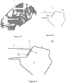
- a roof horn 1 is assembled on a vehicle body 2 by means of a laser braze-welding.
- Such roof lodge 1 has curved longitudinal edges 11 which are housed against the upper portion 21 of a body side.
- the curved portion 12 of the edge 11 of the flag 1 forms against the body side 21 a throat-shaped junction 3 whose cross-sectional profile is substantially V-shaped.
- the free end 13 of the edge 11 extends beyond the junction with the body side 21 and extends substantially parallel thereto, under the groove 3 thus formed in the frame of reference 2.
- the assembly is then performed by laser brazing by depositing a weld bead 4 in the groove 3.
- the method according to the invention makes it possible to propose on a flag 1 and a body side 21 similar, an assembly process which can be replace the braze-welding laser without the need to change the elements to be assembled.
- a bead of glue 5 is deposited along the body side 21 along a discontinuous sizing line, thus providing a succession of dashes of glue along the body side 21 and of glue-free side sections of the body. .
- This adhesive bead 5 is further deposited along the body side 21 so that when the flag 1 is deposited on it (cf. figure 2b ), this adhesive bead 5 is crushed between the body side 21 and the free end 13 of the curved edge 11, substantially below the groove 3 formed at the junction between the roof 1 and the body side 21 as can be seen on the figure 3b .
- the assembly zone is thus defined between the free end 13 of the curved edge 11 and the junction with the body side 21.
- the bead of structural adhesive deposited is discontinuous to leave areas where in the next phase the glue will not be present under the TIG welding bead to prevent its destruction
- the structural adhesive is functional after its polymerization, the latter intervening only after the heat treatment consisting of the passage of the body in cataphoresis, for example.
- weld points 6 consist of weld seams obtained by means of an electric arc welding such as with a non-fusible electrode of TIG (Tungsten Inert Gas) welding type.
- TIG welding beads 6 for example are deposited in the bottom of the groove 3 at the junction of the horn 1 and the body side 21 on the sections of this junction corresponding to the zones without glue of the discontinuous sizing line. In this way, it avoids all risks of fumes related to the burning of the glue and it also avoids the deterioration of the bonding.
- TIG cords of 10 to 15 mm are preferably made along the pavilion in order to maintain it. Thus the geometry of the pavilion is frozen.
- the body is cataphoresed.
- the glue under the effect of the temperature in cataphoresis polymerizes.
- a seal 7 such as a PVC type adhesive, is deposited in the groove 3 all along the latter. or sealant which ensures both the tightness of the assembly and the appearance of the joint by smoothing, see Figures 2d and 3d .
- the glue 7 is smoothed to obtain a connection fillet between the roof and the body side.
- a method according to the invention allows a very economical solution of assembly of these elements. This solution is manual and easy to implement and avoids the use of other more expensive assembly methods such as laser brazing, some sites are not equipped.
Claims (10)
- Verfahren zum Verbinden zweier Elemente aus Metallblech (1, 2), wobei der Rand (11) des ersten Elements (1) ausgestaltet ist, um gegen das zweite Element (2) zur Auflage zu kommen, indem ein Verbindungsbereich gebildet wird, der mindestens durch das freie Ende (13) des Rands (11) des ersten Elements (1) abgegrenzt ist, während auf der Seite des Verbindungsbereichs, der dem freien Ende (13) des Rands (11) des ersten Elements (1) entgegengesetzt ist, das erste und das zweite Element sich beide über diesen Verbindungsbereich hinaus erstrecken, dadurch gekennzeichnet, dass das Verfahren Folgendes umfasst:das Aufbringen einer Klebstoffsnaht (5) auf einem der Elemente (1, 2) derart, dass sich bei dem Verbinden der beiden Elemente (1, 2) die Beleimungslinie zwischen den zwei Elementen (1, 2) an der Stelle des Verbindungsbereichs, bevorzugt entlang des freien Endes (13) des Rands (11) des ersten Elements (1), positioniert, danndas Ausführen mindestens einer Schweißung zwischen den zwei Elementen (1, 2) entlang des Rands des Verbindungsbereichs, dem Rand des Verbindungsbereichs entgegengesetzt, der von dem freien Ende (13) des Rands (11) des ersten Elements (1) gebildet wird, wobei diese Befestigung durch Schweißen es erlaubt, die zwei Elemente zueinander bis zu einem Aushärtungsschritt des Klebstoffs, der das Verbinden abschließt, bewegungslos zu halten.
- Verfahren zum Verbinden nach Anspruch 1, dadurch gekennzeichnet, dass der Klebstoff entlang einer diskontinuierlichen Linie aufgebracht wird, wobei die Beleimungslinie Abschnitte, die frei von Klebstoff sind, aufweist.
- Verfahren zum Verbinden nach Anspruch 1, dadurch gekennzeichnet, dass die Schweißung diskontinuierlich an der Stelle von Abschnitten des Verbindungsbereichs, der von Klebstoff frei sind, eingerichtet wird.
- Verfahren zum Verbinden nach einem der Ansprüche 1 bis 3, dadurch gekennzeichnet, dass das erste Element (1) auf dem zweiten Element (2) unter Bilden eines Bereichs verbunden wird, der durch das freie Ende (13) des Rands (11) des ersten Elements (1) abgegrenzt ist, während sich entgegengesetzt zu dem freien Ende des Rands des ersten Elements (1) die zwei Elemente (1, 2) über diesen Bereich hinaus erstrecken, indem sie sich voneinander abspreizen, und indem sie zwischeneinander eine Nut (3) bilden, in der mindestens eine Schweißnaht hergestellt wird.
- Verfahren nach einem der Ansprüche 1 bis 3, dadurch gekennzeichnet, dass das erste Element eine Bördelung aufweist, die dazu bestimmt ist, gegen das zweite Element zum Aufliegen zu kommen, wobei die Verbindungsbereiche von dem freien Ende der Bördelung und dem Falz, der diese Bördelung bildet, abgegrenzt wird, wobei mindestens eine Schweißnaht an dem Stoß zwischen dem ersten Element und dem zweiten Element an der Stelle des Falzes des ersten Elements eingerichtet wird.
- Verfahren nach einem der Ansprüche 1 bis 4, dadurch gekennzeichnet, dass das erste Element einen gekrümmten Rand (11) aufweist, dessen gekrümmter Teil (12) zum Anschlag gegen das zweite Element (2) gebracht einen Stoß in Form einer Nut (3) mit dem zweiten Element (2) bildet, während das freie Ende (13) des gekrümmten Rands (11) dazu bestimmt ist, sich im Wesentlichen über den Stoß hinaus entlang des zweiten Elements (21), das die Verbindungsbereiche bildet, zu erstrecken, wobei mindestens eine Schweißnaht (6) in der Nut (3), die zwischen dem ersten Element (1) und dem zweiten Element (2) gebildet ist, eingerichtet ist.
- Verfahren nach einem der Ansprüche 1 bis 6, dadurch gekennzeichnet, dass das Schweißen ein Elektroschweißen wie ein Elektroschweißen mit einer nicht schmelzbaren Elektrode vom Typ TIG-(Tungsten Inert Gas)-Schweißen ist.
- Verfahren nach einem der Ansprüche 1 bis 7, dadurch gekennzeichnet, dass weiter entlang des Rands des Verbindungsbereichs, der mit mindestens einer Schweißnaht versehen ist, eine durchgehende Abdichtungsnaht (7), wie eine Dichtung mit Klebstoff vom Typ PVC, Kitt, aufgebracht wird.
- Verbinden zwischen zwei Elementen aus Metallblech (1, 2), wobei der Rand (11) des ersten Elements (1) ausgestaltet ist, um zum Aufliegen gegen das zweite Element (2) zu kommen, indem ein Verbindungsbereich gebildet wird, der mindestens durch das freie Ende (13) des Rands (11) des ersten Elements (1) abgegrenzt ist, während auf der Seite des Verbindungsbereichs, der dem freien Ende (13) des Rands (11) des ersten Elements (1) entgegengesetzt ist, das erste und das zweite Element (1, 2) sich beide über diesen Verbindungsbereich hinaus erstrecken, dadurch gekennzeichnet, dass der Rand (11) des ersten Elements (1) auf dem zweiten Element (2) durch mindestens eine Klebstoffsnaht (5) verbunden ist, die sich an der Stelle des Verbindungsbereichs entlang des freien Endes (13) des Rands (11) des ersten Elements (1) erstreckt, und durch mindestens eine Schweißung (6) zwischen den zwei Elementen (1, 2) entlang des Rands des Verbindungsbereichs, der dem Rand des Verbindungsbereichs, der von dem freien Ende (13) des Rands (11) des ersten Elements (1) gebildet wird, entgegengesetzt ist.
- Kraftfahrzeug, das einen Dachhimmel beinhaltet, der auf den Seiten einer Karosserie gemäß einem Verbindungsverfahren nach einem der Ansprüche 1 bis 3 und 6 bis 8 verbunden ist.
Applications Claiming Priority (2)
| Application Number | Priority Date | Filing Date | Title |
|---|---|---|---|
| FR1558846A FR3041319B1 (fr) | 2015-09-18 | 2015-09-18 | Procede d’assemblage entre deux elements en tole metallique. |
| PCT/FR2016/052283 WO2017046494A1 (fr) | 2015-09-18 | 2016-09-09 | Procede d'assemblage entre deux elements en tole metallique |
Publications (2)
| Publication Number | Publication Date |
|---|---|
| EP3350066A1 EP3350066A1 (de) | 2018-07-25 |
| EP3350066B1 true EP3350066B1 (de) | 2019-08-28 |
Family
ID=54366438
Family Applications (1)
| Application Number | Title | Priority Date | Filing Date |
|---|---|---|---|
| EP16774527.2A Active EP3350066B1 (de) | 2015-09-18 | 2016-09-09 | Montageverfahren zwischen zwei elementen aus blech |
Country Status (3)
| Country | Link |
|---|---|
| EP (1) | EP3350066B1 (de) |
| FR (1) | FR3041319B1 (de) |
| WO (1) | WO2017046494A1 (de) |
Family Cites Families (6)
| Publication number | Priority date | Publication date | Assignee | Title |
|---|---|---|---|---|
| US7004536B2 (en) * | 2002-07-29 | 2006-02-28 | L&L Products, Inc. | Attachment system and method of forming same |
| DE10309634A1 (de) * | 2003-03-04 | 2004-09-23 | Audi Ag | Metallblech-Formteil und Verfahren zur Herstellung eines Metallblechformteils |
| DE102004016849B4 (de) * | 2004-04-07 | 2007-12-13 | Dr.Ing.H.C. F. Porsche Ag | Fahrzeugaufbau eines Kraftfahrzeugs |
| FR2943266B1 (fr) * | 2009-03-17 | 2013-07-05 | Peugeot Citroen Automobiles Sa | Dispositif de soudobrasage |
| JP5240027B2 (ja) * | 2009-04-09 | 2013-07-17 | マツダ株式会社 | 金属板接合構造 |
| EP2682613B1 (de) * | 2011-03-01 | 2016-12-21 | Toyota Jidosha Kabushiki Kaisha | Haftflanschstruktur |
-
2015
- 2015-09-18 FR FR1558846A patent/FR3041319B1/fr not_active Expired - Fee Related
-
2016
- 2016-09-09 WO PCT/FR2016/052283 patent/WO2017046494A1/fr unknown
- 2016-09-09 EP EP16774527.2A patent/EP3350066B1/de active Active
Non-Patent Citations (1)
| Title |
|---|
| None * |
Also Published As
| Publication number | Publication date |
|---|---|
| EP3350066A1 (de) | 2018-07-25 |
| FR3041319B1 (fr) | 2017-10-06 |
| WO2017046494A1 (fr) | 2017-03-23 |
| FR3041319A1 (fr) | 2017-03-24 |
Similar Documents
| Publication | Publication Date | Title |
|---|---|---|
| EP3137252B1 (de) | Verfahren zur montage durch diskontinuierliches thermisches schweissen entlang der naht eines stahlblechs mit einem aluminiumblech mit deponierung eines sauberen materials zur formung einer dichten verbindung auf der naht ; entsprechende anordnung | |
| FR2971191A1 (fr) | Procede d'assemblage d'au moins deux pieces en matiere plastique l'une a l'autre. | |
| EP3194104B1 (de) | Verfahren zur anordnung von zwei blechkomponenten wie etwa fahrzeugkarosseriekomponenten | |
| EP3272616B1 (de) | Verfahren zum zusammenbau eines schienenfahrzeugs | |
| EP3350066B1 (de) | Montageverfahren zwischen zwei elementen aus blech | |
| FR2918014A1 (fr) | Structure de support et d'etancheite d'un logement de feu arriere de vehicule, et procede de montage d'une telle structure. | |
| EP2307166B1 (de) | Lötverfahren zum miteinander befestigen von zwei werkstücken | |
| EP3030371B1 (de) | Verfahren zum schweissen durch lichtbogen- oder laserschweissen zweier übereinander angeordneter bleche aus aluminium oder verzinktem stahl | |
| EP3922511B1 (de) | Verfahren zur befestigung eines schnittstellenträgers an einem gleitschienenprofil eines fahrzeugsitzes durch schweissen | |
| EP2408585B1 (de) | Lötschweissvorrichtung | |
| EP0053053B1 (de) | Sonnenblende, insbesondere für Fahrzeuge | |
| FR2903369A3 (fr) | Procede d'assemblage d'un pavillon sur la partie superieure de la carrosserie d'un vehicule automobile | |
| EP1491807B1 (de) | Bestandteil für Rohrverbindung | |
| FR2958571A1 (fr) | Procede d'assemblage de deux pieces en tole par soudo-brasage. | |
| EP0711614B1 (de) | Verfahren zum Zusammensetzen von zwei Blechplättchen | |
| EP3917806B1 (de) | Fahrzeug mit fensterabdeckung montiert durch klinken | |
| FR3072140B1 (fr) | Procede d’assemblage d’elements en tole metallique | |
| EP3144126A1 (de) | Schweissbares profil und entsprechendes verfahren zum verschweissen von platten aus kunststoffmaterial | |
| EP1762798A1 (de) | Herstellungsverfahren eines Behälters zum Einbau in einem Wärmetauscher | |
| WO2023062296A1 (fr) | Procédé d'assemblage par collage et soudage de deux pièces en tôle | |
| EP2906385B1 (de) | Schweissverfahren zur montage eines aluminiumbleches mit einem anschluss mit einem stahlblech | |
| EP2626481B1 (de) | Kopfschieber zum Abdecken mit Senkrechtfuge | |
| FR2793433A1 (fr) | Procede d'assemblage par soudage d'un element creux en aluminium de carrosserie automobile, et element creux assemble selon le procede | |
| FR2896755A1 (fr) | Montant de pare brise et procede de fabrication d'un tel montant. | |
| FR3040907A1 (fr) | Profile soudable et procede associe, pour la soudure de panneaux en materiau plastique |
Legal Events
| Date | Code | Title | Description |
|---|---|---|---|
| STAA | Information on the status of an ep patent application or granted ep patent |
Free format text: STATUS: THE INTERNATIONAL PUBLICATION HAS BEEN MADE |
|
| PUAI | Public reference made under article 153(3) epc to a published international application that has entered the european phase |
Free format text: ORIGINAL CODE: 0009012 |
|
| STAA | Information on the status of an ep patent application or granted ep patent |
Free format text: STATUS: REQUEST FOR EXAMINATION WAS MADE |
|
| 17P | Request for examination filed |
Effective date: 20180220 |
|
| AK | Designated contracting states |
Kind code of ref document: A1 Designated state(s): AL AT BE BG CH CY CZ DE DK EE ES FI FR GB GR HR HU IE IS IT LI LT LU LV MC MK MT NL NO PL PT RO RS SE SI SK SM TR |
|
| AX | Request for extension of the european patent |
Extension state: BA ME |
|
| DAX | Request for extension of the european patent (deleted) | ||
| RAV | Requested validation state of the european patent: fee paid |
Extension state: MA Effective date: 20180220 |
|
| GRAP | Despatch of communication of intention to grant a patent |
Free format text: ORIGINAL CODE: EPIDOSNIGR1 |
|
| STAA | Information on the status of an ep patent application or granted ep patent |
Free format text: STATUS: GRANT OF PATENT IS INTENDED |
|
| INTG | Intention to grant announced |
Effective date: 20190325 |
|
| GRAS | Grant fee paid |
Free format text: ORIGINAL CODE: EPIDOSNIGR3 |
|
| GRAA | (expected) grant |
Free format text: ORIGINAL CODE: 0009210 |
|
| STAA | Information on the status of an ep patent application or granted ep patent |
Free format text: STATUS: THE PATENT HAS BEEN GRANTED |
|
| AK | Designated contracting states |
Kind code of ref document: B1 Designated state(s): AL AT BE BG CH CY CZ DE DK EE ES FI FR GB GR HR HU IE IS IT LI LT LU LV MC MK MT NL NO PL PT RO RS SE SI SK SM TR |
|
| REG | Reference to a national code |
Ref country code: GB Ref legal event code: FG4D Free format text: NOT ENGLISH |
|
| REG | Reference to a national code |
Ref country code: CH Ref legal event code: EP |
|
| REG | Reference to a national code |
Ref country code: DE Ref legal event code: R096 Ref document number: 602016019534 Country of ref document: DE |
|
| REG | Reference to a national code |
Ref country code: AT Ref legal event code: REF Ref document number: 1172049 Country of ref document: AT Kind code of ref document: T Effective date: 20190915 |
|
| REG | Reference to a national code |
Ref country code: IE Ref legal event code: FG4D Free format text: LANGUAGE OF EP DOCUMENT: FRENCH |
|
| REG | Reference to a national code |
Ref country code: SK Ref legal event code: T3 Ref document number: E 31989 Country of ref document: SK |
|
| REG | Reference to a national code |
Ref country code: NL Ref legal event code: MP Effective date: 20190828 |
|
| REG | Reference to a national code |
Ref country code: LT Ref legal event code: MG4D |
|
| REG | Reference to a national code |
Ref country code: DE Ref legal event code: R084 Ref document number: 602016019534 Country of ref document: DE |
|
| PG25 | Lapsed in a contracting state [announced via postgrant information from national office to epo] |
Ref country code: NO Free format text: LAPSE BECAUSE OF FAILURE TO SUBMIT A TRANSLATION OF THE DESCRIPTION OR TO PAY THE FEE WITHIN THE PRESCRIBED TIME-LIMIT Effective date: 20191128 Ref country code: SE Free format text: LAPSE BECAUSE OF FAILURE TO SUBMIT A TRANSLATION OF THE DESCRIPTION OR TO PAY THE FEE WITHIN THE PRESCRIBED TIME-LIMIT Effective date: 20190828 Ref country code: FI Free format text: LAPSE BECAUSE OF FAILURE TO SUBMIT A TRANSLATION OF THE DESCRIPTION OR TO PAY THE FEE WITHIN THE PRESCRIBED TIME-LIMIT Effective date: 20190828 Ref country code: HR Free format text: LAPSE BECAUSE OF FAILURE TO SUBMIT A TRANSLATION OF THE DESCRIPTION OR TO PAY THE FEE WITHIN THE PRESCRIBED TIME-LIMIT Effective date: 20190828 Ref country code: PT Free format text: LAPSE BECAUSE OF FAILURE TO SUBMIT A TRANSLATION OF THE DESCRIPTION OR TO PAY THE FEE WITHIN THE PRESCRIBED TIME-LIMIT Effective date: 20191230 Ref country code: LT Free format text: LAPSE BECAUSE OF FAILURE TO SUBMIT A TRANSLATION OF THE DESCRIPTION OR TO PAY THE FEE WITHIN THE PRESCRIBED TIME-LIMIT Effective date: 20190828 Ref country code: BG Free format text: LAPSE BECAUSE OF FAILURE TO SUBMIT A TRANSLATION OF THE DESCRIPTION OR TO PAY THE FEE WITHIN THE PRESCRIBED TIME-LIMIT Effective date: 20191128 Ref country code: NL Free format text: LAPSE BECAUSE OF FAILURE TO SUBMIT A TRANSLATION OF THE DESCRIPTION OR TO PAY THE FEE WITHIN THE PRESCRIBED TIME-LIMIT Effective date: 20190828 |
|
| PG25 | Lapsed in a contracting state [announced via postgrant information from national office to epo] |
Ref country code: AL Free format text: LAPSE BECAUSE OF FAILURE TO SUBMIT A TRANSLATION OF THE DESCRIPTION OR TO PAY THE FEE WITHIN THE PRESCRIBED TIME-LIMIT Effective date: 20190828 Ref country code: ES Free format text: LAPSE BECAUSE OF FAILURE TO SUBMIT A TRANSLATION OF THE DESCRIPTION OR TO PAY THE FEE WITHIN THE PRESCRIBED TIME-LIMIT Effective date: 20190828 Ref country code: GR Free format text: LAPSE BECAUSE OF FAILURE TO SUBMIT A TRANSLATION OF THE DESCRIPTION OR TO PAY THE FEE WITHIN THE PRESCRIBED TIME-LIMIT Effective date: 20191129 Ref country code: LV Free format text: LAPSE BECAUSE OF FAILURE TO SUBMIT A TRANSLATION OF THE DESCRIPTION OR TO PAY THE FEE WITHIN THE PRESCRIBED TIME-LIMIT Effective date: 20190828 Ref country code: RS Free format text: LAPSE BECAUSE OF FAILURE TO SUBMIT A TRANSLATION OF THE DESCRIPTION OR TO PAY THE FEE WITHIN THE PRESCRIBED TIME-LIMIT Effective date: 20190828 Ref country code: IS Free format text: LAPSE BECAUSE OF FAILURE TO SUBMIT A TRANSLATION OF THE DESCRIPTION OR TO PAY THE FEE WITHIN THE PRESCRIBED TIME-LIMIT Effective date: 20191228 |
|
| REG | Reference to a national code |
Ref country code: GB Ref legal event code: 746 Effective date: 20200207 |
|
| REG | Reference to a national code |
Ref country code: AT Ref legal event code: MK05 Ref document number: 1172049 Country of ref document: AT Kind code of ref document: T Effective date: 20190828 |
|
| PG25 | Lapsed in a contracting state [announced via postgrant information from national office to epo] |
Ref country code: TR Free format text: LAPSE BECAUSE OF FAILURE TO SUBMIT A TRANSLATION OF THE DESCRIPTION OR TO PAY THE FEE WITHIN THE PRESCRIBED TIME-LIMIT Effective date: 20190828 |
|
| PG25 | Lapsed in a contracting state [announced via postgrant information from national office to epo] |
Ref country code: RO Free format text: LAPSE BECAUSE OF FAILURE TO SUBMIT A TRANSLATION OF THE DESCRIPTION OR TO PAY THE FEE WITHIN THE PRESCRIBED TIME-LIMIT Effective date: 20190828 Ref country code: PL Free format text: LAPSE BECAUSE OF FAILURE TO SUBMIT A TRANSLATION OF THE DESCRIPTION OR TO PAY THE FEE WITHIN THE PRESCRIBED TIME-LIMIT Effective date: 20190828 Ref country code: EE Free format text: LAPSE BECAUSE OF FAILURE TO SUBMIT A TRANSLATION OF THE DESCRIPTION OR TO PAY THE FEE WITHIN THE PRESCRIBED TIME-LIMIT Effective date: 20190828 Ref country code: AT Free format text: LAPSE BECAUSE OF FAILURE TO SUBMIT A TRANSLATION OF THE DESCRIPTION OR TO PAY THE FEE WITHIN THE PRESCRIBED TIME-LIMIT Effective date: 20190828 Ref country code: IT Free format text: LAPSE BECAUSE OF FAILURE TO SUBMIT A TRANSLATION OF THE DESCRIPTION OR TO PAY THE FEE WITHIN THE PRESCRIBED TIME-LIMIT Effective date: 20190828 Ref country code: DK Free format text: LAPSE BECAUSE OF FAILURE TO SUBMIT A TRANSLATION OF THE DESCRIPTION OR TO PAY THE FEE WITHIN THE PRESCRIBED TIME-LIMIT Effective date: 20190828 |
|
| PG25 | Lapsed in a contracting state [announced via postgrant information from national office to epo] |
Ref country code: MC Free format text: LAPSE BECAUSE OF FAILURE TO SUBMIT A TRANSLATION OF THE DESCRIPTION OR TO PAY THE FEE WITHIN THE PRESCRIBED TIME-LIMIT Effective date: 20190828 Ref country code: IS Free format text: LAPSE BECAUSE OF FAILURE TO SUBMIT A TRANSLATION OF THE DESCRIPTION OR TO PAY THE FEE WITHIN THE PRESCRIBED TIME-LIMIT Effective date: 20200224 Ref country code: CZ Free format text: LAPSE BECAUSE OF FAILURE TO SUBMIT A TRANSLATION OF THE DESCRIPTION OR TO PAY THE FEE WITHIN THE PRESCRIBED TIME-LIMIT Effective date: 20190828 Ref country code: SM Free format text: LAPSE BECAUSE OF FAILURE TO SUBMIT A TRANSLATION OF THE DESCRIPTION OR TO PAY THE FEE WITHIN THE PRESCRIBED TIME-LIMIT Effective date: 20190828 |
|
| REG | Reference to a national code |
Ref country code: CH Ref legal event code: PL |
|
| REG | Reference to a national code |
Ref country code: DE Ref legal event code: R097 Ref document number: 602016019534 Country of ref document: DE |
|
| PLBE | No opposition filed within time limit |
Free format text: ORIGINAL CODE: 0009261 |
|
| STAA | Information on the status of an ep patent application or granted ep patent |
Free format text: STATUS: NO OPPOSITION FILED WITHIN TIME LIMIT |
|
| PG2D | Information on lapse in contracting state deleted |
Ref country code: IS |
|
| PG25 | Lapsed in a contracting state [announced via postgrant information from national office to epo] |
Ref country code: LI Free format text: LAPSE BECAUSE OF NON-PAYMENT OF DUE FEES Effective date: 20190930 Ref country code: IE Free format text: LAPSE BECAUSE OF NON-PAYMENT OF DUE FEES Effective date: 20190909 Ref country code: LU Free format text: LAPSE BECAUSE OF NON-PAYMENT OF DUE FEES Effective date: 20190909 Ref country code: CH Free format text: LAPSE BECAUSE OF NON-PAYMENT OF DUE FEES Effective date: 20190930 |
|
| REG | Reference to a national code |
Ref country code: BE Ref legal event code: MM Effective date: 20190930 |
|
| 26N | No opposition filed |
Effective date: 20200603 |
|
| PG25 | Lapsed in a contracting state [announced via postgrant information from national office to epo] |
Ref country code: SI Free format text: LAPSE BECAUSE OF FAILURE TO SUBMIT A TRANSLATION OF THE DESCRIPTION OR TO PAY THE FEE WITHIN THE PRESCRIBED TIME-LIMIT Effective date: 20190828 Ref country code: BE Free format text: LAPSE BECAUSE OF NON-PAYMENT OF DUE FEES Effective date: 20190930 |
|
| PG25 | Lapsed in a contracting state [announced via postgrant information from national office to epo] |
Ref country code: CY Free format text: LAPSE BECAUSE OF FAILURE TO SUBMIT A TRANSLATION OF THE DESCRIPTION OR TO PAY THE FEE WITHIN THE PRESCRIBED TIME-LIMIT Effective date: 20190828 |
|
| VS25 | Lapsed in a validation state [announced via postgrant information from nat. office to epo] |
Ref country code: MA Free format text: LAPSE BECAUSE OF FAILURE TO SUBMIT A TRANSLATION OF THE DESCRIPTION OR TO PAY THE FEE WITHIN THE PRESCRIBED TIME-LIMIT Effective date: 20190828 |
|
| PG25 | Lapsed in a contracting state [announced via postgrant information from national office to epo] |
Ref country code: HU Free format text: LAPSE BECAUSE OF FAILURE TO SUBMIT A TRANSLATION OF THE DESCRIPTION OR TO PAY THE FEE WITHIN THE PRESCRIBED TIME-LIMIT; INVALID AB INITIO Effective date: 20160909 Ref country code: MT Free format text: LAPSE BECAUSE OF FAILURE TO SUBMIT A TRANSLATION OF THE DESCRIPTION OR TO PAY THE FEE WITHIN THE PRESCRIBED TIME-LIMIT Effective date: 20190828 |
|
| PG25 | Lapsed in a contracting state [announced via postgrant information from national office to epo] |
Ref country code: MK Free format text: LAPSE BECAUSE OF FAILURE TO SUBMIT A TRANSLATION OF THE DESCRIPTION OR TO PAY THE FEE WITHIN THE PRESCRIBED TIME-LIMIT Effective date: 20190828 |
|
| PGFP | Annual fee paid to national office [announced via postgrant information from national office to epo] |
Ref country code: GB Payment date: 20230823 Year of fee payment: 8 |
|
| PGFP | Annual fee paid to national office [announced via postgrant information from national office to epo] |
Ref country code: SK Payment date: 20230830 Year of fee payment: 8 Ref country code: FR Payment date: 20230822 Year of fee payment: 8 Ref country code: DE Payment date: 20230822 Year of fee payment: 8 |