EP3349269A1 - Battery module, and battery pack and vehicle comprising same - Google Patents
Battery module, and battery pack and vehicle comprising same Download PDFInfo
- Publication number
- EP3349269A1 EP3349269A1 EP17813466.4A EP17813466A EP3349269A1 EP 3349269 A1 EP3349269 A1 EP 3349269A1 EP 17813466 A EP17813466 A EP 17813466A EP 3349269 A1 EP3349269 A1 EP 3349269A1
- Authority
- EP
- European Patent Office
- Prior art keywords
- battery
- connection member
- electrode lead
- battery cell
- cell
- Prior art date
- Legal status (The legal status is an assumption and is not a legal conclusion. Google has not performed a legal analysis and makes no representation as to the accuracy of the status listed.)
- Granted
Links
- 238000007789 sealing Methods 0.000 claims description 31
- 230000004308 accommodation Effects 0.000 claims description 26
- 238000003466 welding Methods 0.000 claims description 23
- 239000010410 layer Substances 0.000 description 10
- 230000008878 coupling Effects 0.000 description 8
- 238000010168 coupling process Methods 0.000 description 8
- 238000005859 coupling reaction Methods 0.000 description 8
- 229910052751 metal Inorganic materials 0.000 description 8
- 239000002184 metal Substances 0.000 description 8
- 239000011149 active material Substances 0.000 description 5
- 229910052782 aluminium Inorganic materials 0.000 description 5
- XAGFODPZIPBFFR-UHFFFAOYSA-N aluminium Chemical compound [Al] XAGFODPZIPBFFR-UHFFFAOYSA-N 0.000 description 5
- 239000000463 material Substances 0.000 description 4
- 230000000694 effects Effects 0.000 description 3
- 239000003792 electrolyte Substances 0.000 description 3
- 239000002002 slurry Substances 0.000 description 3
- 229910000640 Fe alloy Inorganic materials 0.000 description 2
- XEEYBQQBJWHFJM-UHFFFAOYSA-N Iron Chemical compound [Fe] XEEYBQQBJWHFJM-UHFFFAOYSA-N 0.000 description 2
- PXHVJJICTQNCMI-UHFFFAOYSA-N Nickel Chemical compound [Ni] PXHVJJICTQNCMI-UHFFFAOYSA-N 0.000 description 2
- 239000012790 adhesive layer Substances 0.000 description 2
- 238000010586 diagram Methods 0.000 description 2
- 229910001339 C alloy Inorganic materials 0.000 description 1
- OKTJSMMVPCPJKN-UHFFFAOYSA-N Carbon Chemical compound [C] OKTJSMMVPCPJKN-UHFFFAOYSA-N 0.000 description 1
- VYZAMTAEIAYCRO-UHFFFAOYSA-N Chromium Chemical compound [Cr] VYZAMTAEIAYCRO-UHFFFAOYSA-N 0.000 description 1
- 229910000599 Cr alloy Inorganic materials 0.000 description 1
- 229910000990 Ni alloy Inorganic materials 0.000 description 1
- 239000011230 binding agent Substances 0.000 description 1
- 239000011651 chromium Substances 0.000 description 1
- 239000004020 conductor Substances 0.000 description 1
- 238000001816 cooling Methods 0.000 description 1
- 238000003487 electrochemical reaction Methods 0.000 description 1
- 238000004146 energy storage Methods 0.000 description 1
- 230000002708 enhancing effect Effects 0.000 description 1
- 229910052742 iron Inorganic materials 0.000 description 1
- WPBNNNQJVZRUHP-UHFFFAOYSA-L manganese(2+);methyl n-[[2-(methoxycarbonylcarbamothioylamino)phenyl]carbamothioyl]carbamate;n-[2-(sulfidocarbothioylamino)ethyl]carbamodithioate Chemical compound [Mn+2].[S-]C(=S)NCCNC([S-])=S.COC(=O)NC(=S)NC1=CC=CC=C1NC(=S)NC(=O)OC WPBNNNQJVZRUHP-UHFFFAOYSA-L 0.000 description 1
- 238000000034 method Methods 0.000 description 1
- 238000012986 modification Methods 0.000 description 1
- 230000004048 modification Effects 0.000 description 1
- 230000000149 penetrating effect Effects 0.000 description 1
- 239000004014 plasticizer Substances 0.000 description 1
- 239000002861 polymer material Substances 0.000 description 1
- 239000002904 solvent Substances 0.000 description 1
- 238000003756 stirring Methods 0.000 description 1
Images


Classifications
-
- H—ELECTRICITY
- H01—ELECTRIC ELEMENTS
- H01M—PROCESSES OR MEANS, e.g. BATTERIES, FOR THE DIRECT CONVERSION OF CHEMICAL ENERGY INTO ELECTRICAL ENERGY
- H01M50/00—Constructional details or processes of manufacture of the non-active parts of electrochemical cells other than fuel cells, e.g. hybrid cells
- H01M50/20—Mountings; Secondary casings or frames; Racks, modules or packs; Suspension devices; Shock absorbers; Transport or carrying devices; Holders
-
- B—PERFORMING OPERATIONS; TRANSPORTING
- B60—VEHICLES IN GENERAL
- B60L—PROPULSION OF ELECTRICALLY-PROPELLED VEHICLES; SUPPLYING ELECTRIC POWER FOR AUXILIARY EQUIPMENT OF ELECTRICALLY-PROPELLED VEHICLES; ELECTRODYNAMIC BRAKE SYSTEMS FOR VEHICLES IN GENERAL; MAGNETIC SUSPENSION OR LEVITATION FOR VEHICLES; MONITORING OPERATING VARIABLES OF ELECTRICALLY-PROPELLED VEHICLES; ELECTRIC SAFETY DEVICES FOR ELECTRICALLY-PROPELLED VEHICLES
- B60L50/00—Electric propulsion with power supplied within the vehicle
- B60L50/50—Electric propulsion with power supplied within the vehicle using propulsion power supplied by batteries or fuel cells
- B60L50/60—Electric propulsion with power supplied within the vehicle using propulsion power supplied by batteries or fuel cells using power supplied by batteries
- B60L50/64—Constructional details of batteries specially adapted for electric vehicles
-
- B—PERFORMING OPERATIONS; TRANSPORTING
- B60—VEHICLES IN GENERAL
- B60L—PROPULSION OF ELECTRICALLY-PROPELLED VEHICLES; SUPPLYING ELECTRIC POWER FOR AUXILIARY EQUIPMENT OF ELECTRICALLY-PROPELLED VEHICLES; ELECTRODYNAMIC BRAKE SYSTEMS FOR VEHICLES IN GENERAL; MAGNETIC SUSPENSION OR LEVITATION FOR VEHICLES; MONITORING OPERATING VARIABLES OF ELECTRICALLY-PROPELLED VEHICLES; ELECTRIC SAFETY DEVICES FOR ELECTRICALLY-PROPELLED VEHICLES
- B60L50/00—Electric propulsion with power supplied within the vehicle
- B60L50/50—Electric propulsion with power supplied within the vehicle using propulsion power supplied by batteries or fuel cells
- B60L50/60—Electric propulsion with power supplied within the vehicle using propulsion power supplied by batteries or fuel cells using power supplied by batteries
- B60L50/66—Arrangements of batteries
-
- C—CHEMISTRY; METALLURGY
- C22—METALLURGY; FERROUS OR NON-FERROUS ALLOYS; TREATMENT OF ALLOYS OR NON-FERROUS METALS
- C22C—ALLOYS
- C22C21/00—Alloys based on aluminium
-
- H—ELECTRICITY
- H01—ELECTRIC ELEMENTS
- H01M—PROCESSES OR MEANS, e.g. BATTERIES, FOR THE DIRECT CONVERSION OF CHEMICAL ENERGY INTO ELECTRICAL ENERGY
- H01M50/00—Constructional details or processes of manufacture of the non-active parts of electrochemical cells other than fuel cells, e.g. hybrid cells
- H01M50/20—Mountings; Secondary casings or frames; Racks, modules or packs; Suspension devices; Shock absorbers; Transport or carrying devices; Holders
- H01M50/204—Racks, modules or packs for multiple batteries or multiple cells
- H01M50/207—Racks, modules or packs for multiple batteries or multiple cells characterised by their shape
- H01M50/211—Racks, modules or packs for multiple batteries or multiple cells characterised by their shape adapted for pouch cells
-
- H—ELECTRICITY
- H01—ELECTRIC ELEMENTS
- H01M—PROCESSES OR MEANS, e.g. BATTERIES, FOR THE DIRECT CONVERSION OF CHEMICAL ENERGY INTO ELECTRICAL ENERGY
- H01M50/00—Constructional details or processes of manufacture of the non-active parts of electrochemical cells other than fuel cells, e.g. hybrid cells
- H01M50/50—Current conducting connections for cells or batteries
- H01M50/502—Interconnectors for connecting terminals of adjacent batteries; Interconnectors for connecting cells outside a battery casing
- H01M50/503—Interconnectors for connecting terminals of adjacent batteries; Interconnectors for connecting cells outside a battery casing characterised by the shape of the interconnectors
-
- H—ELECTRICITY
- H01—ELECTRIC ELEMENTS
- H01M—PROCESSES OR MEANS, e.g. BATTERIES, FOR THE DIRECT CONVERSION OF CHEMICAL ENERGY INTO ELECTRICAL ENERGY
- H01M50/00—Constructional details or processes of manufacture of the non-active parts of electrochemical cells other than fuel cells, e.g. hybrid cells
- H01M50/50—Current conducting connections for cells or batteries
- H01M50/502—Interconnectors for connecting terminals of adjacent batteries; Interconnectors for connecting cells outside a battery casing
- H01M50/514—Methods for interconnecting adjacent batteries or cells
- H01M50/516—Methods for interconnecting adjacent batteries or cells by welding, soldering or brazing
-
- H—ELECTRICITY
- H01—ELECTRIC ELEMENTS
- H01M—PROCESSES OR MEANS, e.g. BATTERIES, FOR THE DIRECT CONVERSION OF CHEMICAL ENERGY INTO ELECTRICAL ENERGY
- H01M50/00—Constructional details or processes of manufacture of the non-active parts of electrochemical cells other than fuel cells, e.g. hybrid cells
- H01M50/50—Current conducting connections for cells or batteries
- H01M50/531—Electrode connections inside a battery casing
- H01M50/54—Connection of several leads or tabs of plate-like electrode stacks, e.g. electrode pole straps or bridges
-
- H—ELECTRICITY
- H01—ELECTRIC ELEMENTS
- H01M—PROCESSES OR MEANS, e.g. BATTERIES, FOR THE DIRECT CONVERSION OF CHEMICAL ENERGY INTO ELECTRICAL ENERGY
- H01M2220/00—Batteries for particular applications
- H01M2220/20—Batteries in motive systems, e.g. vehicle, ship, plane
-
- Y—GENERAL TAGGING OF NEW TECHNOLOGICAL DEVELOPMENTS; GENERAL TAGGING OF CROSS-SECTIONAL TECHNOLOGIES SPANNING OVER SEVERAL SECTIONS OF THE IPC; TECHNICAL SUBJECTS COVERED BY FORMER USPC CROSS-REFERENCE ART COLLECTIONS [XRACs] AND DIGESTS
- Y02—TECHNOLOGIES OR APPLICATIONS FOR MITIGATION OR ADAPTATION AGAINST CLIMATE CHANGE
- Y02E—REDUCTION OF GREENHOUSE GAS [GHG] EMISSIONS, RELATED TO ENERGY GENERATION, TRANSMISSION OR DISTRIBUTION
- Y02E60/00—Enabling technologies; Technologies with a potential or indirect contribution to GHG emissions mitigation
- Y02E60/10—Energy storage using batteries
-
- Y—GENERAL TAGGING OF NEW TECHNOLOGICAL DEVELOPMENTS; GENERAL TAGGING OF CROSS-SECTIONAL TECHNOLOGIES SPANNING OVER SEVERAL SECTIONS OF THE IPC; TECHNICAL SUBJECTS COVERED BY FORMER USPC CROSS-REFERENCE ART COLLECTIONS [XRACs] AND DIGESTS
- Y02—TECHNOLOGIES OR APPLICATIONS FOR MITIGATION OR ADAPTATION AGAINST CLIMATE CHANGE
- Y02T—CLIMATE CHANGE MITIGATION TECHNOLOGIES RELATED TO TRANSPORTATION
- Y02T10/00—Road transport of goods or passengers
- Y02T10/60—Other road transportation technologies with climate change mitigation effect
- Y02T10/70—Energy storage systems for electromobility, e.g. batteries
Definitions
- the present disclosure relates to a battery module, and a battery pack and a vehicle comprising the same.
- Secondary batteries are highly applicable to a wide range of products and have electrical characteristics with high energy density. Such secondary batteries are applied not only to portable electronic devices but also to electric vehicles, hybrid vehicles, and electric power storage devices, driven by electric driving sources.
- a battery pack applied to an electric vehicle and the like is configured so that a plurality of battery modules, each having a plurality of battery cells, are connected to obtain a high output.
- Each battery cell may be repeatedly charged and discharged by an electrochemical reaction among components including a positive electrode current collector, a negative electrode current collector, a separator, an active material, an electrolyte and the like.
- a battery module applied to a battery pack is configured by stacking a plurality of battery cells and then connecting the plurality of battery cells in series or in parallel.
- electrode leads of the battery cells may be bent in any direction and then coupled to each other by welding.
- the plurality of battery cells are disposed side by side in one direction.
- the electrode leads of the battery cells are also disposed side by side in one direction at any surface of the battery cells.
- the electrode leads are coupled in an upper or lower space of one surface of the battery cells.
- a separate space (the upper or lower space of the battery cells) is required for coupling the electrode leads to the battery module, and this space occupies a certain volume in the battery module, which is disadvantageous in terms of the energy volume efficiency of the battery module.
- the present disclosure is designed to solve the problems of the related art, and therefore the present disclosure is directed to providing a battery module for enhancing the energy volume efficiency of the battery module, and a battery pack and a vehicle comprising the battery module.
- the present disclosure is directed to providing a battery module which may enhance the energy volume efficiency of the battery module by newly configuring and disposing battery cells and a connection member for electrically connecting the battery cells, and a battery pack and a vehicle comprising the battery module.
- the present disclosure provides a battery module having a plurality of battery cells.
- the battery module includes: a plurality of battery cells, each having an electrode assembly, a case for accommodating the electrode assembly, and an electrode lead composed of a positive electrode lead and a negative electrode lead connected to the electrode assembly and exposed out of the case; and a connection member configured to electrically connect the battery cells, wherein the plurality of battery cells are classified into a first battery group having battery cells disposed side by side in a first direction and a second battery group having battery cells disposed side by side in the first direction so that electrode leads of the battery cells thereof face electrode leads of the battery cells of the first battery group, wherein the connection member is located between the first battery group and the second battery group, wherein the electrode leads of the battery cells are connected to the connection member, respectively, wherein an electrode lead of any one battery cell of the first battery group is in contact with any one of an upper surface and a lower surface of the connection member, and wherein an electrode lead of a battery cell of the second battery group, which is located to face the any one battery cell, is in contact with the other one
- the battery cell may include an accommodation portion in which the electrode assembly is accommodated and a sealing portion for sealing the accommodation portion, the connection member and the electrode lead may be coupled by means of welding, and a welding face of the connection member and the electrode lead may be located in a region facing the sealing portion.
- the welding face of the electrode lead of the any one battery cell and the connection member may be located in a region facing the sealing portion of the other battery cell.
- the welding face of the electrode lead of the other battery cell and the connection member may be located in a region facing the sealing portion of the any one battery cell.
- the case may include an upper pouch and a lower pouch whose rim portions are sealed to each other
- the accommodation space for accommodating the electrode assembly may be formed in any one of the upper pouch and the lower pouch, and in case of battery cells connected to each other by the connection member, the accommodation space may be formed in different pouches.
- the positive electrode lead and the negative electrode lead of the battery cell may be exposed at the same side of the case, and at least the positive electrode lead and the negative electrode lead of the any one battery cell may be located so that a partial region of surfaces thereof faces the positive electrode lead and the negative electrode lead of the other battery cell, based on the connection member.
- both ends of the connection member in a second direction which is perpendicular to the first direction when being observed from the above, may be spaced apart by a predetermined distance from the accommodation portions of both battery cells connected to each other by the connection member.
- connection member may be in contact with one surface of the sealing portion of the any one battery cell, and at least a part of the upper surface of the connection member may be in contact with one surface of the sealing portion of the facing battery cell.
- the battery module may have an inner space, and a cell frame may be further provided so that the first battery group, the second battery group and the connection member are located in the inner space.
- the present disclosure may provide a battery pack, comprising the battery module described above.
- the present disclosure may provide a vehicle, comprising the battery pack described above.
- the energy volume efficiency of the battery module may be improved by coupling electrode leads of the battery cells and a connection member in different ways.
- the space required for coupling the electrode leads may be minimized since the electrode leads of the battery cells are respectively coupled to an upper surface and a lower surface of the connection member.
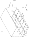
- FIG. 1 is an exploded perspective view showing a battery module according to an embodiment of the present disclosure
- FIG. 2 is a perspective view showing a battery module according to an embodiment of the present disclosure in an assembled state
- FIG. 3 is a plane view showing the battery module of FIG. 1 , from which the upper body of the cell frame is excluded.
- a battery module 10 has a plurality of battery cells 100.
- the battery cell 100 may be provided as a secondary battery.
- the battery cell 100 may be provided as a pouch-type secondary battery.
- the battery cell 100 of the present disclosure will be described as a pouch-type secondary battery as an example.
- the battery module 10 includes a battery cell 100, a connection member 200, a cell frame 300 and a connector 400.
- the battery cell 100 may be provided in plural.
- the plurality of battery cells 100 are classified into a first battery group 101 and a second battery group 102.
- the battery cells 100 of the first battery group 101 may be disposed side by side in the first direction 12.
- a direction in which the plurality of battery cells 100 of the first battery group 101 are arranged side by side is referred to as a first direction 12.
- a direction perpendicular to the first direction 12 is referred to as a second direction 14.
- a direction perpendicular to both the first direction 12 and the second direction 14 is referred to as a third direction 16.
- the battery cells 100 of the second battery group 102 may be disposed side by side in the first direction 12.
- the first battery group 101 and the second battery group 102 may be spaced apart from each other by a predetermined distance in the second direction 14.
- the first battery group 101 and the second battery group 102 may be located so that the electrode leads 140 of the battery cells 100 thereof face each other.
- the first battery group 101 and the second battery group 102 respectively include six battery cells 100 as an example, but the number of the battery cells 100 is not limited thereto.
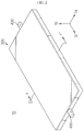
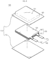
- FIG. 4 is an exploded perspective view showing the battery cell of FIG. 1
- FIG. 5 is an assembled perspective view showing the battery cell of FIG. 1 .
- the battery cell 100 includes a case 110, an electrode assembly 120, an electrode tab 130 and an electrode lead 140.
- the case 110 has an accommodation space 151. Inside the case 110, an electrode assembly 120 and an electrolyte, explained later, are positioned. A central region of the case 110 is provided to protrude upward.
- the case 110 includes an upper pouch 111 and a lower pouch 112.
- the upper pouch 111 and the lower pouch 112 are combined with each other to form the accommodation space 151.
- a central region of the upper pouch 111 has a concave shape protruding upward.
- the lower pouch 112 is located under the upper pouch 111 in the third direction 16.
- the accommodation space 151 of the case 110 may also be formed in the lower pouch 112, different from the above.
- the accommodation space 151 may also be formed in both the upper pouch 111 and the lower pouch 112.
- the upper pouch 111 and the lower pouch 112 respectively have a sealing portion 160.
- the sealing portion 160 of the upper pouch 111 and the sealing portion 160 of the lower pouch 112 may be provided to face each other.
- the sealing portion 160 of the upper pouch 111 and the sealing portion 160 of the lower pouch 112 may be bonded to each other by thermal bonding or the like.
- the accommodation space 151 may be sealed by bonding the sealing portions 160.
- the case 110 may have an outer insulating layer, a metal layer, and an inner adhesive layer.
- the outer insulating layer may prevent exterior moisture, gas or the like from penetrating therein.
- the metal layer may improve the mechanical strength of the case 110.
- the metal layer may be made of aluminum.
- the metal layer may be made of any one selected from an alloy of iron, carbon, chromium and manganese, an alloy of iron and nickel, aluminum or equivalents thereof. When the metal layer uses a material containing iron, mechanical strength may be enhanced. When the metal layer is made of aluminum, good ductility may be ensured.
- Aluminum is a desired material of the metal layer.
- the outer insulating layer and the inner adhesive layer may be made of a polymer material.
- the electrode assembly 120 includes a positive electrode plate, a negative electrode plate, and a separator.
- the electrode assembly 120 may be configured so that at least one positive electrode plate and at least one negative electrode plate are disposed with a separator being interposed therebetween.
- the electrode assembly 120 may be configured so that a plurality of positive electrode plates and a plurality of negative electrode plates are alternately stacked. Alternatively, the electrode assembly 120 may also be configured so that one positive electrode plate and one negative electrode plate are wound.
- the electrode plate of the electrode assembly 120 includes a current collector and active material slurry coated on one or both sides of the current collector.
- the active material slurry may be formed by stirring a solvent in a state where a granular active material, an auxiliary conductor, a binder, and a plasticizer are added thereto.
- Each electrode plate may have an uncoated portion corresponding to a region where the active material slurry is not coated. In the uncoated portion, an electrode tab 130 corresponding to each electrode plate may be formed.
- the electrode tab 130 is extended to protrude from the electrode assembly 120.
- the electrode tab 130 includes a positive electrode tab 131 and a negative electrode tab 132.
- the positive electrode tab 131 may extend from the uncoated portion of the positive electrode plate, and the negative electrode tab 132 may extend from the uncoated portion of the negative electrode plate.
- One positive electrode tab 131 and one negative electrode tab 132 may be provided in the battery cell 100, respectively.
- a plurality of positive electrode tabs 131 and a plurality of negative electrode tabs 132 may also be provided.
- one positive electrode plate and one negative electrode plate are included in the electrode assembly 120 of the battery cell 100
- one positive electrode tab 131 and one negative electrode tab 132 may be included.
- a plurality of positive electrode tabs 131 and a plurality of negative electrode tabs 132 may be included, respectively.
- a plurality of positive electrode plates and a plurality of negative electrode plates are included in the electrode assembly 120, a plurality of positive electrode tabs 131 and a plurality of negative electrode tabs 132 may be included, and one electrode tab 130 may be provided to one electrode plate.
- the electrode lead 140 may electrically connect the battery cell 100 to other external devices.
- the electrode lead 140 may include a positive electrode lead 141 and a negative electrode lead 142.
- the electrode lead 140 may be provided to extend from the inside to the outside of the pouch case 110. A portion of the electrode lead 140 may be interposed between the sealing portions 160.
- the electrode lead 140 is connected to the electrode tab 130.
- the electrode lead 140 of the present disclosure may include both the positive electrode lead 141 and the negative electrode lead 142 at one side of the case 110.
- the battery cell 100 has an accommodation portion 150 and a sealing portion 160.
- the accommodation portion 150 is a portion where the electrode assembly 120 is accommodated in the battery cell 100.
- the sealing portion 160 is sealing portions at four sides of the case 110 surrounding the accommodation portion 150.
- connection member 200 may electrically connect the battery cells 100 of the first battery group 101 and the battery cells 100 of the second battery group 102.
- the connection member 200 may be located between the first battery group 101 and the second battery group 102.
- the first battery group 101, the connection member 200 and the second battery group 102 may be disposed in order side by side along the second direction 14.
- the connection member 200 may be provided so that its length elongates in the first direction 12.
- the first battery group 101 and the second battery group 102 may be located symmetrically based on the connection member 200.
- the electrode leads 140 of the battery cells 100 of the first battery group 101 may be coupled to the connection member 200.
- the electrode leads 140 of the battery cells 100 of the second battery group 102 may be coupled to the connection member 200.
- an electrode lead 140 of any one battery cell 100 of the first battery group 101 may be in contact with any one of an upper surface 201 and a lower surface 202 of the connection member 200.
- An electrode lead 140 of a battery cell 100 of the second battery group 102 which is located to face any one battery cell 100 of the first battery group 101, may be in contact with the other one of the upper surface 201 and the lower surface 202 of the connection member 200.
- any one battery cell 104 of the first battery group 101 is defined as a first battery cell 104.
- the battery cell 103 of the second battery group 102 located to face the first battery cell 104 is defined as a second battery cell 103.
- FIG. 6 is a cross-sectional view showing the battery module of FIG. 2 , observed in the A-A direction.
- connection member 200 the connection member 200 and the battery cells 100 will be described in detail.
- the connection member 200 may be located between the first battery cell 104 and the second battery cell 103.
- the electrode lead 140 of the first battery cell 104 may be in contact with the lower surface 202 of the connection member 200.
- the electrode lead 140 of the second battery cell 103 may be in contact with the upper surface 201 of the connection member 200.
- the electrode lead 140 of the first battery cell 104 and the electrode lead 140 of the second battery cell 103 may be provided above and below the connection member 200 in the third direction 16.
- the electrode lead 140 of the first battery cell 104 and the electrode lead 140 of the second battery cell 103 may be located so that at least a part of surfaces thereof face each other based on the connection member 200.
- the battery cells 100 respectively connected to the connection member 200 may be connected in series or in parallel.
- the positive electrode leads of the battery cells 100 connected to the connection member 200 may be connected through a single connection portion (not shown) in the connection member 200.
- the negative electrode leads of the battery cell 100 connected to the connection member 200 may be connected through a single connection portion (not shown) in the connection member 200.
- electrode leads 140 of neighboring battery cells 100 may be connected in series through a separate connection portion (not shown) in the connection member 200.
- the space required for coupling may be reduced, compared to the case where the electrode lead 140 is bent and coupled in a separate space. In this case, the space required for electrically connecting the electrode leads 140 is reduced at the battery module 10, which may improve the energy volume efficiency of the battery module 10.
- At least a part of the lower surface 202 of the connection member 200 may be in contact with the sealing portion 160 of the first battery cell 104. At least a part of the upper surface 201 of the connection member 200 may be in contact with the sealing portion 160 of the second battery cell 103.
- Both ends 203, 204 of the connection member 200 in the second direction 14 may be located spaced apart from the accommodation portion 150 of the battery cell 100 by a predetermined distance, respectively.
- one end 203 of the connection member 200 in the second direction 14 may be located spaced apart from the accommodation portion 150 of the first battery cell 104.
- the other end 204 of the connection member 200 in the second direction 14 may be located spaced apart from the accommodation portion 150 of the second battery cell 103.
- the battery cells 100 connected to each other through the connection member 200 may have the accommodation space 151 in different pouches thereof.
- the first battery cell 104 and the second battery cell 103 may be located rotationally symmetrically based on the connection member 200.
- the first battery cell 104 may be located so that the accommodation space 151 is formed in the upper pouch 111 thereof.
- the second battery cell 103 may be located so that the accommodation space 151 is formed in the lower pouch 112 thereof.
- the upper pouch 111 and the lower pouch 112 of the first battery cell 104 and the second battery cell 103 are defined so that a pouch located in an upper portion in the third direction 16 of FIG. 6 is the upper pouch 111, and a pouch located in a lower portion in the third direction 16 is the lower pouch 112.
- the battery cells 100 facing each other in the second direction 14 based on the connection member 200 are provided rotationally symmetrically, thereby minimizing the empty space in the battery module 10. Since the empty space in the battery module 10 is minimized, the energy volume efficiency of the battery module 10 may be improved.
- the empty space between the battery cells 100 may be utilized to the maximum by allowing the electrode leads 140 to respectively contact the upper and lower surfaces 201, 202 of the connection member 200 located between the battery modules 10 and also allowing the connection member 200 to be located in a space above the sealing portion 160 of each battery cell 100. By doing so, the energy volume efficiency of the battery module 10 may be improved.
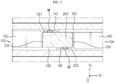
- FIG. 7 is a diagram showing a welding face of the connection member and the electrode lead of FIG. 6 .
- connection member 200 and the electrode lead 140 may be coupled by means of welding.
- the electrode lead 140 of the first battery cell 104 is in contact with the lower surface 202 of the connection member 200 and may be coupled thereto by welding.
- the electrode lead 140 of the second battery cell 103 is in contact with the upper surface 201 of the connection member 200 and may be coupled thereto by welding.
- a welding face (WF) of the connection member 200 and the electrode lead 140 may be located in a region which faces the sealing portion 160 of the battery cell 100.
- the welding face (WF) of the electrode lead 140 of the first battery cell 104 and the connection member 200 may be located in a region which faces the sealing portion 160 of the first battery cell 104 located in an upper portion in the third direction 16.
- the welding face (WF) of the electrode lead 140 of the second battery cell 103 and the connection member 200 may be located in a region which faces the sealing portion 160 of the second battery cell 103 located in a lower portion in the third direction 16.
- the sealing portion 160 of the battery cell 100, the connection member 200 and the welding face (WF) may be located to be stacked up and down in the third direction 16.
- the welding may be performed using various known welding methods, for example ultrasonic welding, laser welding or the like.
- the electrode leads 140 when the connection member 200 and the electrode lead 140 are coupled, the electrode leads 140 come into contact with the upper and lower surfaces 201, 202 of the connection member 200 without being bent, and then are coupled thereto by welding, which ensures easy coupling between the connection member 200 and the electrode leads 140.
- the electrode leads 140 are contacted and coupled to the upper and lower surfaces 201, 202 of the connection member 200, which does not need a separate space for coupling the electrode leads 140, and thus the space required for coupling the electrode leads 140 may be minimized in the battery module 10. By doing so, the energy volume efficiency of the battery module 10 may be improved.
- components of the battery module 10 may be located at the inside of the cell frame 300.
- the cell frame 300 may protect the battery cells 100 therein against an external impact.
- the cell frame 300 has an inner space.
- the first battery group 101, the connection member 200 and the second battery group 102 may be located in the inner space.
- the first battery group 101, the connection member 200 and the second battery group 102 may be located in order along the second direction 14.
- the cell frame 300 may be provided in a rectangular parallelepiped shape as a whole.
- the cell frame 300 may be made of a material with excellent thermal conductivity and good rigidity.
- the cell frame 300 may be made of metal.
- the cell frame 300 may be made of aluminum.
- a part of inner sides of the cell frame 300 may be in contact with the battery cell 100.
- the cell frame 300 may be in contact with the battery cell 100 to receive the heat generated from the battery cell 100 and discharge the heat to the outside.
- the cell frame 300 may be made of a material with excellent thermal conductivity and discharge the heat generated at the battery cell 100 to the outside, thereby cooling the battery cell 100.
- the cell frame 300 has an upper body 310 and a lower body 320.
- the upper body 310 may have a rectangular shape, when being observed from the above.
- the upper body 310 may have an empty space therein.
- An inner surface of the upper body 310 located at an upper portion in the third direction 16 may be in contact with the surface of the battery cells 100 of the first battery group 101 and the surface of the battery cells 100 of the second battery group 102.
- the lower body 320 may be located below the upper body 310 in the third direction 16.
- the lower body 320 may have an empty space.
- the upper body 310 and the lower body 320 may be combined with each other to form an inner space.
- An inner surface of the lower body 320 located at a lower portion in the third direction 16 may be in contact with the surface of the battery cells 100 of the first battery group 101 and the battery cells 100 of the second battery group 102.
- a part of the inner surfaces of the upper body 310 and the lower body 320 may come into contact with the battery cells 100 to emit the heat generated at the battery cells 100.
- the cell frame 300 may cool the battery cells 100.
- the connector 400 may electrically connect the battery module 10 to an external electric device.
- the connector 400 may be connected to the connection member 200.
- the connector 400 may be provided in a pair.
- the pair of connectors 400 may be respectively connected to both ends of the connection member 200 in the first direction 12.
- the pair of connectors 400 may be formed through the lower body 320 of the cell frame 300.
- FIG. 8 is a perspective view showing a battery module 10 according to another embodiment of the present disclosure.
- a plurality of battery modules 10 of the present disclosure as depicted in FIG. 1 may be stacked in one direction. If a plurality of battery modules 10 of FIG. 1 are provided, the battery module 10 may have an increased energy capacity.
- the battery pack according to the present disclosure may include at least one battery module 10 described above.
- the battery pack may further include a pack case for accommodating the battery module 10, and various devices for controlling charge/discharge of the battery module 10.
- a battery management system BMS
- a current sensor e.g., a current sensor
- a fuse e.g., a fuse
- the battery module 10 according to the present disclosure may be applied to vehicles such as electric vehicles and hybrid vehicles.
- the vehicle according to the present disclosure may include at least one battery pack including the battery module 10 according to the embodiment in the present disclosure.
- the electrode leads 140 of the battery cells 100 may be located to face each other.
- the electrode leads 140 of the battery cells 100 may be coupled to the connection member 200 located between the first battery group 101 and the second battery group 102.
Abstract
Description
- The present disclosure relates to a battery module, and a battery pack and a vehicle comprising the same.
- The present application claims priority to Korean Patent Application No.
10-2016-0073360 filed on June 13, 2016 - Secondary batteries are highly applicable to a wide range of products and have electrical characteristics with high energy density. Such secondary batteries are applied not only to portable electronic devices but also to electric vehicles, hybrid vehicles, and electric power storage devices, driven by electric driving sources.
- A battery pack applied to an electric vehicle and the like is configured so that a plurality of battery modules, each having a plurality of battery cells, are connected to obtain a high output. Each battery cell may be repeatedly charged and discharged by an electrochemical reaction among components including a positive electrode current collector, a negative electrode current collector, a separator, an active material, an electrolyte and the like.
- Meanwhile, along with an increased need for a large capacity structure and utilization as energy storage sources in recent years, there is a growing demand for a multi-module battery pack in which a plurality of battery modules, each having a plurality of secondary batteries connected in series or in parallel, are aggregated.
- Generally, a battery module applied to a battery pack is configured by stacking a plurality of battery cells and then connecting the plurality of battery cells in series or in parallel.
- For the electric connection of the battery cells, electrode leads of the battery cells may be bent in any direction and then coupled to each other by welding. Generally, the plurality of battery cells are disposed side by side in one direction. At this time, the electrode leads of the battery cells are also disposed side by side in one direction at any surface of the battery cells. After that, the electrode leads are coupled in an upper or lower space of one surface of the battery cells. In this case, in order to couple the plurality of electrode leads, a separate space (the upper or lower space of the battery cells) is required for coupling the electrode leads to the battery module, and this space occupies a certain volume in the battery module, which is disadvantageous in terms of the energy volume efficiency of the battery module.
- The present disclosure is designed to solve the problems of the related art, and therefore the present disclosure is directed to providing a battery module for enhancing the energy volume efficiency of the battery module, and a battery pack and a vehicle comprising the battery module.
- In addition, the present disclosure is directed to providing a battery module which may enhance the energy volume efficiency of the battery module by newly configuring and disposing battery cells and a connection member for electrically connecting the battery cells, and a battery pack and a vehicle comprising the battery module.
- The present disclosure is not limited thereto, and other objects not mentioned herein may be clearly understood by those skilled in the art from the following description.
- The present disclosure provides a battery module having a plurality of battery cells.
- According to an embodiment of the present disclosure, the battery module includes: a plurality of battery cells, each having an electrode assembly, a case for accommodating the electrode assembly, and an electrode lead composed of a positive electrode lead and a negative electrode lead connected to the electrode assembly and exposed out of the case; and a connection member configured to electrically connect the battery cells, wherein the plurality of battery cells are classified into a first battery group having battery cells disposed side by side in a first direction and a second battery group having battery cells disposed side by side in the first direction so that electrode leads of the battery cells thereof face electrode leads of the battery cells of the first battery group, wherein the connection member is located between the first battery group and the second battery group, wherein the electrode leads of the battery cells are connected to the connection member, respectively, wherein an electrode lead of any one battery cell of the first battery group is in contact with any one of an upper surface and a lower surface of the connection member, and wherein an electrode lead of a battery cell of the second battery group, which is located to face the any one battery cell, is in contact with the other one of the upper surface and the lower surface of the connection member.
- In an embodiment, the battery cell may include an accommodation portion in which the electrode assembly is accommodated and a sealing portion for sealing the accommodation portion, the connection member and the electrode lead may be coupled by means of welding, and a welding face of the connection member and the electrode lead may be located in a region facing the sealing portion.
- In an embodiment, the welding face of the electrode lead of the any one battery cell and the connection member may be located in a region facing the sealing portion of the other battery cell.
- In an embodiment, the welding face of the electrode lead of the other battery cell and the connection member may be located in a region facing the sealing portion of the any one battery cell.
- In an embodiment, the case may include an upper pouch and a lower pouch whose rim portions are sealed to each other, the accommodation space for accommodating the electrode assembly may be formed in any one of the upper pouch and the lower pouch, and in case of battery cells connected to each other by the connection member, the accommodation space may be formed in different pouches.
- In an embodiment, the positive electrode lead and the negative electrode lead of the battery cell may be exposed at the same side of the case, and at least the positive electrode lead and the negative electrode lead of the any one battery cell may be located so that a partial region of surfaces thereof faces the positive electrode lead and the negative electrode lead of the other battery cell, based on the connection member.
- In an embodiment, both ends of the connection member in a second direction, which is perpendicular to the first direction when being observed from the above, may be spaced apart by a predetermined distance from the accommodation portions of both battery cells connected to each other by the connection member.
- In an embodiment, at least a part of the lower surface of the connection member may be in contact with one surface of the sealing portion of the any one battery cell, and at least a part of the upper surface of the connection member may be in contact with one surface of the sealing portion of the facing battery cell.
- In an embodiment, the battery module may have an inner space, and a cell frame may be further provided so that the first battery group, the second battery group and the connection member are located in the inner space.
- The present disclosure may provide a battery pack, comprising the battery module described above.
- The present disclosure may provide a vehicle, comprising the battery pack described above.
- According to an embodiment of the present disclosure, the energy volume efficiency of the battery module may be improved by coupling electrode leads of the battery cells and a connection member in different ways.
- In addition, according to an embodiment of the present disclosure, the space required for coupling the electrode leads may be minimized since the electrode leads of the battery cells are respectively coupled to an upper surface and a lower surface of the connection member.
- The effects of the present disclosure are not limited to the above, and effects not mentioned herein may be clearly understood by those skilled in the art from the specification and the accompanying drawings.
-
-
FIG. 1 is an exploded perspective view showing a battery module according to an embodiment of the present disclosure. -
FIG. 2 is a perspective view showing a battery module according to an embodiment of the present disclosure in an assembled state. -
FIG. 3 is a plane view showing the battery module ofFIG. 1 , from which the upper body of the cell frame is excluded. -
FIG. 4 is an exploded perspective view showing the battery cell ofFIG. 1 . -
FIG. 5 is an assembled perspective view showing the battery cell ofFIG. 1 . -
FIG. 6 is a cross-sectional view showing the battery module ofFIG. 2 , observed in the A-A direction. -
FIG. 7 is a diagram showing a welding face of the connection member and the electrode lead ofFIG. 6 . -
FIG. 8 is a perspective view showing a battery module according to another embodiment of the present disclosure. - Hereinafter, embodiments of the present disclosure will be described in more detail with reference to the accompanying drawings. The embodiments of the present disclosure may be modified in various ways, and the scope of the present disclosure should not be construed as being limited to the embodiments described below. The embodiments are provided to more fully illustrate the present disclosure to those skilled in the art. Thus, the shapes of the components in the figures may be exaggerated to emphasize a clearer description. In addition, terms and words used in the specification and the claims should not be construed as being limited to ordinary or dictionary meanings, but interpreted based on the meanings and concepts corresponding to technical aspects of the present disclosure on the basis of the principle that the inventor is allowed to define terms appropriately for the best explanation.
-
FIG. 1 is an exploded perspective view showing a battery module according to an embodiment of the present disclosure,FIG. 2 is a perspective view showing a battery module according to an embodiment of the present disclosure in an assembled state, andFIG. 3 is a plane view showing the battery module ofFIG. 1 , from which the upper body of the cell frame is excluded. - Referring to
FIGS. 1 to 3 , abattery module 10 has a plurality ofbattery cells 100. Thebattery cell 100 may be provided as a secondary battery. For example, thebattery cell 100 may be provided as a pouch-type secondary battery. Hereinafter, thebattery cell 100 of the present disclosure will be described as a pouch-type secondary battery as an example. - The
battery module 10 includes abattery cell 100, aconnection member 200, acell frame 300 and aconnector 400. - The
battery cell 100 may be provided in plural. The plurality ofbattery cells 100 are classified into afirst battery group 101 and asecond battery group 102. - The
battery cells 100 of thefirst battery group 101 may be disposed side by side in thefirst direction 12. Here, a direction in which the plurality ofbattery cells 100 of thefirst battery group 101 are arranged side by side is referred to as afirst direction 12. When being observed from the above, a direction perpendicular to thefirst direction 12 is referred to as asecond direction 14. A direction perpendicular to both thefirst direction 12 and thesecond direction 14 is referred to as athird direction 16. - The
battery cells 100 of thesecond battery group 102 may be disposed side by side in thefirst direction 12. Thefirst battery group 101 and thesecond battery group 102 may be spaced apart from each other by a predetermined distance in thesecond direction 14. Thefirst battery group 101 and thesecond battery group 102 may be located so that the electrode leads 140 of thebattery cells 100 thereof face each other. In an embodiment of the present disclosure, thefirst battery group 101 and thesecond battery group 102 respectively include sixbattery cells 100 as an example, but the number of thebattery cells 100 is not limited thereto. -
FIG. 4 is an exploded perspective view showing the battery cell ofFIG. 1 , andFIG. 5 is an assembled perspective view showing the battery cell ofFIG. 1 . - Referring to
FIGS. 4 and5 , thebattery cell 100 includes acase 110, anelectrode assembly 120, anelectrode tab 130 and anelectrode lead 140. - The
case 110 has anaccommodation space 151. Inside thecase 110, anelectrode assembly 120 and an electrolyte, explained later, are positioned. A central region of thecase 110 is provided to protrude upward. Thecase 110 includes an upper pouch 111 and alower pouch 112. - The upper pouch 111 and the
lower pouch 112 are combined with each other to form theaccommodation space 151. A central region of the upper pouch 111 has a concave shape protruding upward. Thelower pouch 112 is located under the upper pouch 111 in thethird direction 16. - Even though the accommodation space is formed only in the upper pouch 111 in the above embodiment, the
accommodation space 151 of thecase 110 may also be formed in thelower pouch 112, different from the above. As an alternative, theaccommodation space 151 may also be formed in both the upper pouch 111 and thelower pouch 112. - The upper pouch 111 and the
lower pouch 112 respectively have a sealingportion 160. The sealingportion 160 of the upper pouch 111 and the sealingportion 160 of thelower pouch 112 may be provided to face each other. The sealingportion 160 of the upper pouch 111 and the sealingportion 160 of thelower pouch 112 may be bonded to each other by thermal bonding or the like. Theaccommodation space 151 may be sealed by bonding the sealingportions 160. - An electrolyte and an
electrode assembly 120 are accommodated in theaccommodation space 151 of thecase 110. Thecase 110 may have an outer insulating layer, a metal layer, and an inner adhesive layer. The outer insulating layer may prevent exterior moisture, gas or the like from penetrating therein. The metal layer may improve the mechanical strength of thecase 110. The metal layer may be made of aluminum. Alternatively, the metal layer may be made of any one selected from an alloy of iron, carbon, chromium and manganese, an alloy of iron and nickel, aluminum or equivalents thereof. When the metal layer uses a material containing iron, mechanical strength may be enhanced. When the metal layer is made of aluminum, good ductility may be ensured. Aluminum is a desired material of the metal layer. The outer insulating layer and the inner adhesive layer may be made of a polymer material. - The
electrode assembly 120 includes a positive electrode plate, a negative electrode plate, and a separator. Theelectrode assembly 120 may be configured so that at least one positive electrode plate and at least one negative electrode plate are disposed with a separator being interposed therebetween. Theelectrode assembly 120 may be configured so that a plurality of positive electrode plates and a plurality of negative electrode plates are alternately stacked. Alternatively, theelectrode assembly 120 may also be configured so that one positive electrode plate and one negative electrode plate are wound. - The electrode plate of the
electrode assembly 120 includes a current collector and active material slurry coated on one or both sides of the current collector. The active material slurry may be formed by stirring a solvent in a state where a granular active material, an auxiliary conductor, a binder, and a plasticizer are added thereto. Each electrode plate may have an uncoated portion corresponding to a region where the active material slurry is not coated. In the uncoated portion, anelectrode tab 130 corresponding to each electrode plate may be formed. - The
electrode tab 130 is extended to protrude from theelectrode assembly 120. Theelectrode tab 130 includes a positive electrode tab 131 and anegative electrode tab 132. The positive electrode tab 131 may extend from the uncoated portion of the positive electrode plate, and thenegative electrode tab 132 may extend from the uncoated portion of the negative electrode plate. - One positive electrode tab 131 and one
negative electrode tab 132 may be provided in thebattery cell 100, respectively. Alternatively, a plurality of positive electrode tabs 131 and a plurality ofnegative electrode tabs 132 may also be provided. For example, if one positive electrode plate and one negative electrode plate are included in theelectrode assembly 120 of thebattery cell 100, one positive electrode tab 131 and onenegative electrode tab 132 may be included. Alternatively, a plurality of positive electrode tabs 131 and a plurality ofnegative electrode tabs 132 may be included, respectively. If a plurality of positive electrode plates and a plurality of negative electrode plates are included in theelectrode assembly 120, a plurality of positive electrode tabs 131 and a plurality ofnegative electrode tabs 132 may be included, and oneelectrode tab 130 may be provided to one electrode plate. - The
electrode lead 140 may electrically connect thebattery cell 100 to other external devices. Theelectrode lead 140 may include apositive electrode lead 141 and anegative electrode lead 142. Theelectrode lead 140 may be provided to extend from the inside to the outside of thepouch case 110. A portion of theelectrode lead 140 may be interposed between the sealingportions 160. Theelectrode lead 140 is connected to theelectrode tab 130. Theelectrode lead 140 of the present disclosure may include both thepositive electrode lead 141 and thenegative electrode lead 142 at one side of thecase 110. - The
battery cell 100 has anaccommodation portion 150 and a sealingportion 160. Here, theaccommodation portion 150 is a portion where theelectrode assembly 120 is accommodated in thebattery cell 100. The sealingportion 160 is sealing portions at four sides of thecase 110 surrounding theaccommodation portion 150. - Referring to
FIGS. 1 to 3 again, theconnection member 200 may electrically connect thebattery cells 100 of thefirst battery group 101 and thebattery cells 100 of thesecond battery group 102. Theconnection member 200 may be located between thefirst battery group 101 and thesecond battery group 102. Thefirst battery group 101, theconnection member 200 and thesecond battery group 102 may be disposed in order side by side along thesecond direction 14. Theconnection member 200 may be provided so that its length elongates in thefirst direction 12. Thefirst battery group 101 and thesecond battery group 102 may be located symmetrically based on theconnection member 200. - The electrode leads 140 of the
battery cells 100 of thefirst battery group 101 may be coupled to theconnection member 200. In addition, the electrode leads 140 of thebattery cells 100 of thesecond battery group 102 may be coupled to theconnection member 200. For example, anelectrode lead 140 of any onebattery cell 100 of thefirst battery group 101 may be in contact with any one of anupper surface 201 and alower surface 202 of theconnection member 200. - An
electrode lead 140 of abattery cell 100 of thesecond battery group 102, which is located to face any onebattery cell 100 of thefirst battery group 101, may be in contact with the other one of theupper surface 201 and thelower surface 202 of theconnection member 200. - Here, any one
battery cell 104 of thefirst battery group 101 is defined as afirst battery cell 104. Also, thebattery cell 103 of thesecond battery group 102 located to face thefirst battery cell 104 is defined as asecond battery cell 103. -
FIG. 6 is a cross-sectional view showing the battery module ofFIG. 2 , observed in the A-A direction. Hereinafter, referring toFIG. 6 , the connection relationship of theconnection member 200 and thebattery cells 100 will be described in detail. - The
connection member 200 may be located between thefirst battery cell 104 and thesecond battery cell 103. Theelectrode lead 140 of thefirst battery cell 104 may be in contact with thelower surface 202 of theconnection member 200. Theelectrode lead 140 of thesecond battery cell 103 may be in contact with theupper surface 201 of theconnection member 200. For example, theelectrode lead 140 of thefirst battery cell 104 and theelectrode lead 140 of thesecond battery cell 103 may be provided above and below theconnection member 200 in thethird direction 16. Theelectrode lead 140 of thefirst battery cell 104 and theelectrode lead 140 of thesecond battery cell 103 may be located so that at least a part of surfaces thereof face each other based on theconnection member 200. - Though not shown in the figures, the
battery cells 100 respectively connected to theconnection member 200 may be connected in series or in parallel. For example, the positive electrode leads of thebattery cells 100 connected to theconnection member 200 may be connected through a single connection portion (not shown) in theconnection member 200. In addition, the negative electrode leads of thebattery cell 100 connected to theconnection member 200 may be connected through a single connection portion (not shown) in theconnection member 200. As an alternative, electrode leads 140 of neighboringbattery cells 100 may be connected in series through a separate connection portion (not shown) in theconnection member 200. - If the
electrode lead 140 of thefirst battery cell 104 and theelectrode lead 140 of thesecond battery cell 103 are contacted and coupled to the upper andlower surfaces connection member 200, respectively, the space required for coupling may be reduced, compared to the case where theelectrode lead 140 is bent and coupled in a separate space. In this case, the space required for electrically connecting the electrode leads 140 is reduced at thebattery module 10, which may improve the energy volume efficiency of thebattery module 10. - At least a part of the
lower surface 202 of theconnection member 200 may be in contact with the sealingportion 160 of thefirst battery cell 104. At least a part of theupper surface 201 of theconnection member 200 may be in contact with the sealingportion 160 of thesecond battery cell 103. - Both ends 203, 204 of the
connection member 200 in thesecond direction 14 may be located spaced apart from theaccommodation portion 150 of thebattery cell 100 by a predetermined distance, respectively. For example, oneend 203 of theconnection member 200 in thesecond direction 14 may be located spaced apart from theaccommodation portion 150 of thefirst battery cell 104. Theother end 204 of theconnection member 200 in thesecond direction 14 may be located spaced apart from theaccommodation portion 150 of thesecond battery cell 103. - The
battery cells 100 connected to each other through theconnection member 200 may have theaccommodation space 151 in different pouches thereof. For example, thefirst battery cell 104 and thesecond battery cell 103 may be located rotationally symmetrically based on theconnection member 200. For example, thefirst battery cell 104 may be located so that theaccommodation space 151 is formed in the upper pouch 111 thereof. Thesecond battery cell 103 may be located so that theaccommodation space 151 is formed in thelower pouch 112 thereof. Here, the upper pouch 111 and thelower pouch 112 of thefirst battery cell 104 and thesecond battery cell 103 are defined so that a pouch located in an upper portion in thethird direction 16 ofFIG. 6 is the upper pouch 111, and a pouch located in a lower portion in thethird direction 16 is thelower pouch 112. - As described above, the
battery cells 100 facing each other in thesecond direction 14 based on theconnection member 200 are provided rotationally symmetrically, thereby minimizing the empty space in thebattery module 10. Since the empty space in thebattery module 10 is minimized, the energy volume efficiency of thebattery module 10 may be improved. In addition, the empty space between thebattery cells 100 may be utilized to the maximum by allowing the electrode leads 140 to respectively contact the upper andlower surfaces connection member 200 located between thebattery modules 10 and also allowing theconnection member 200 to be located in a space above the sealingportion 160 of eachbattery cell 100. By doing so, the energy volume efficiency of thebattery module 10 may be improved. -
FIG. 7 is a diagram showing a welding face of the connection member and the electrode lead ofFIG. 6 . - Referring to
FIG. 7 , theconnection member 200 and theelectrode lead 140 may be coupled by means of welding. Theelectrode lead 140 of thefirst battery cell 104 is in contact with thelower surface 202 of theconnection member 200 and may be coupled thereto by welding. Theelectrode lead 140 of thesecond battery cell 103 is in contact with theupper surface 201 of theconnection member 200 and may be coupled thereto by welding. - A welding face (WF) of the
connection member 200 and theelectrode lead 140 may be located in a region which faces the sealingportion 160 of thebattery cell 100. For example, the welding face (WF) of theelectrode lead 140 of thefirst battery cell 104 and theconnection member 200 may be located in a region which faces the sealingportion 160 of thefirst battery cell 104 located in an upper portion in thethird direction 16. The welding face (WF) of theelectrode lead 140 of thesecond battery cell 103 and theconnection member 200 may be located in a region which faces the sealingportion 160 of thesecond battery cell 103 located in a lower portion in thethird direction 16. In other words, the sealingportion 160 of thebattery cell 100, theconnection member 200 and the welding face (WF) may be located to be stacked up and down in thethird direction 16. - The welding may be performed using various known welding methods, for example ultrasonic welding, laser welding or the like.
- In the present disclosure, when the
connection member 200 and theelectrode lead 140 are coupled, the electrode leads 140 come into contact with the upper andlower surfaces connection member 200 without being bent, and then are coupled thereto by welding, which ensures easy coupling between theconnection member 200 and the electrode leads 140. In addition, the electrode leads 140 are contacted and coupled to the upper andlower surfaces connection member 200, which does not need a separate space for coupling the electrode leads 140, and thus the space required for coupling the electrode leads 140 may be minimized in thebattery module 10. By doing so, the energy volume efficiency of thebattery module 10 may be improved. - Referring to
FIGS. 1 to 3 again, components of thebattery module 10 may be located at the inside of thecell frame 300. Thecell frame 300 may protect thebattery cells 100 therein against an external impact. - The
cell frame 300 has an inner space. Thefirst battery group 101, theconnection member 200 and thesecond battery group 102 may be located in the inner space. Thefirst battery group 101, theconnection member 200 and thesecond battery group 102 may be located in order along thesecond direction 14. - The
cell frame 300 may be provided in a rectangular parallelepiped shape as a whole. Thecell frame 300 may be made of a material with excellent thermal conductivity and good rigidity. Thecell frame 300 may be made of metal. For example, thecell frame 300 may be made of aluminum. A part of inner sides of thecell frame 300 may be in contact with thebattery cell 100. Thecell frame 300 may be in contact with thebattery cell 100 to receive the heat generated from thebattery cell 100 and discharge the heat to the outside. In other words, thecell frame 300 may be made of a material with excellent thermal conductivity and discharge the heat generated at thebattery cell 100 to the outside, thereby cooling thebattery cell 100. - The
cell frame 300 has anupper body 310 and alower body 320. Theupper body 310 may have a rectangular shape, when being observed from the above. Theupper body 310 may have an empty space therein. An inner surface of theupper body 310 located at an upper portion in thethird direction 16 may be in contact with the surface of thebattery cells 100 of thefirst battery group 101 and the surface of thebattery cells 100 of thesecond battery group 102. - The
lower body 320 may be located below theupper body 310 in thethird direction 16. Thelower body 320 may have an empty space. Theupper body 310 and thelower body 320 may be combined with each other to form an inner space. An inner surface of thelower body 320 located at a lower portion in thethird direction 16 may be in contact with the surface of thebattery cells 100 of thefirst battery group 101 and thebattery cells 100 of thesecond battery group 102. - A part of the inner surfaces of the
upper body 310 and thelower body 320 may come into contact with thebattery cells 100 to emit the heat generated at thebattery cells 100. In other words, thecell frame 300 may cool thebattery cells 100. - The
connector 400 may electrically connect thebattery module 10 to an external electric device. Theconnector 400 may be connected to theconnection member 200. For example, theconnector 400 may be provided in a pair. The pair ofconnectors 400 may be respectively connected to both ends of theconnection member 200 in thefirst direction 12. The pair ofconnectors 400 may be formed through thelower body 320 of thecell frame 300. -
FIG. 8 is a perspective view showing abattery module 10 according to another embodiment of the present disclosure. Referring toFIG. 8 , a plurality ofbattery modules 10 of the present disclosure as depicted inFIG. 1 may be stacked in one direction. If a plurality ofbattery modules 10 ofFIG. 1 are provided, thebattery module 10 may have an increased energy capacity. - The battery pack according to the present disclosure may include at least one
battery module 10 described above. In addition to thebattery module 10, the battery pack may further include a pack case for accommodating thebattery module 10, and various devices for controlling charge/discharge of thebattery module 10. For example, a battery management system (BMS), a current sensor, a fuse, and the like may be further included. - The
battery module 10 according to the present disclosure may be applied to vehicles such as electric vehicles and hybrid vehicles. The vehicle according to the present disclosure may include at least one battery pack including thebattery module 10 according to the embodiment in the present disclosure. - As described above, in the
battery module 10 of the present disclosure, the electrode leads 140 of thebattery cells 100 may be located to face each other. In addition, the electrode leads 140 of thebattery cells 100 may be coupled to theconnection member 200 located between thefirst battery group 101 and thesecond battery group 102. By utilizing the space between thebattery cells 100 to the maximum as described above, it is possible to minimize the space required for coupling the electrode leads 140 in thebattery module 10. By doing so, the energy volume efficiency of thebattery module 10 may be improved. - The above description is illustrative of the present disclosure. Also, the above disclosure is intended to illustrate and explain the preferred embodiments of the present disclosure, and the present disclosure may be used in various other combinations, modifications, and environments. In other words, the present disclosure may be changed or modified within the scope of the concept of the invention disclosed herein, within the equivalent scope of the disclosure, and/or within the skill and knowledge of the art. The described embodiments illustrate the best state of the art to implement the technical idea of the present disclosure, and various changes may be made thereto as being demanded for specific applications and uses of the present disclosure. Accordingly, the above description is not intended to limit the present disclosure to the embodiments. Also, the appended claims should be construed as encompassing such other embodiments.
Claims (11)
- A battery module, comprising:a plurality of battery cells, each having an electrode assembly, a case for accommodating the electrode assembly, and an electrode lead composed of a positive electrode lead and a negative electrode lead connected to the electrode assembly and exposed out of the case; anda connection member configured to electrically connect the battery cells,wherein the plurality of battery cells are classified into a first battery group having battery cells disposed side by side in a first direction and a second battery group having battery cells disposed side by side in the first direction so that electrode leads of the battery cells thereof face electrode leads of the battery cells of the first battery group,wherein the connection member is located between the first battery group and the second battery group,wherein the electrode leads of the battery cells are connected to the connection member, respectively,wherein an electrode lead of any one battery cell of the first battery group is in contact with any one of an upper surface and a lower surface of the connection member, andwherein an electrode lead of a battery cell of the second battery group, which is located to face the any one battery cell, is in contact with the other one of the upper surface and the lower surface of the connection member.
- The battery module according to claim 1,
wherein the battery cell includes an accommodation portion in which the electrode assembly is accommodated and a sealing portion for sealing the accommodation portion,
wherein the connection member and the electrode lead are coupled by means of welding, and
wherein a welding face of the connection member and the electrode lead is located in a region facing the sealing portion. - The battery module according to claim 2,
wherein the welding face of the electrode lead of the any one battery cell and the connection member is located in a region facing the sealing portion of the other battery cell. - The battery module according to claim 3,
wherein the welding face of the electrode lead of the other battery cell and the connection member is located in a region facing the sealing portion of the any one battery cell. - The battery module according to claim 1,
wherein the case includes an upper pouch and a lower pouch whose rim portions are sealed to each other, and the accommodation space for accommodating the electrode assembly is formed in any one of the upper pouch and the lower pouch, and
wherein in case of battery cells connected to each other by the connection member, the accommodation space is formed in different pouches. - The battery module according to claim 1,
wherein the positive electrode lead and the negative electrode lead of the battery cell are exposed at the same side of the case, and at least the positive electrode lead and the negative electrode lead of the any one battery cell are located so that a partial region of surfaces thereof faces the positive electrode lead and the negative electrode lead of the other battery cell, based on the connection member. - The battery module according to claim 2,
wherein both ends of the connection member in a second direction, which is perpendicular to the first direction when being observed from the above, are spaced apart by a predetermined distance from the accommodation portions of both battery cells connected to each other by the connection member. - The battery module according to claim 2,
wherein at least a part of the lower surface of the connection member is in contact with one surface of the sealing portion of the any one battery cell, and at least a part of the upper surface of the connection member is in contact with one surface of the sealing portion of the facing battery cell. - The battery module according to claim 1,
wherein the battery module has an inner space, and a cell frame is further provided so that the first battery group, the second battery group and the connection member are located in the inner space. - A battery pack, comprising a battery module defined in any one of claims 1 to 9.
- A vehicle, comprising a battery pack defined in claim 10.
Priority Applications (1)
| Application Number | Priority Date | Filing Date | Title |
|---|---|---|---|
| PL17813466T PL3349269T3 (en) | 2016-06-13 | 2017-03-16 | Battery module, and battery pack and vehicle comprising the same |
Applications Claiming Priority (2)
| Application Number | Priority Date | Filing Date | Title |
|---|---|---|---|
| KR1020160073360A KR102059077B1 (en) | 2016-06-13 | 2016-06-13 | Battery module, battery pack comprising the battery module and vehicle comprising the battery pack |
| PCT/KR2017/002852 WO2017217641A1 (en) | 2016-06-13 | 2017-03-16 | Battery module, and battery pack and vehicle comprising same |
Publications (3)
| Publication Number | Publication Date |
|---|---|
| EP3349269A1 true EP3349269A1 (en) | 2018-07-18 |
| EP3349269A4 EP3349269A4 (en) | 2019-04-17 |
| EP3349269B1 EP3349269B1 (en) | 2021-07-14 |
Family
ID=60664108
Family Applications (1)
| Application Number | Title | Priority Date | Filing Date |
|---|---|---|---|
| EP17813466.4A Active EP3349269B1 (en) | 2016-06-13 | 2017-03-16 | Battery module, and battery pack and vehicle comprising the same |
Country Status (7)
| Country | Link |
|---|---|
| US (1) | US10547037B2 (en) |
| EP (1) | EP3349269B1 (en) |
| JP (1) | JP6619090B2 (en) |
| KR (1) | KR102059077B1 (en) |
| CN (1) | CN108140779B (en) |
| PL (1) | PL3349269T3 (en) |
| WO (1) | WO2017217641A1 (en) |
Cited By (1)
| Publication number | Priority date | Publication date | Assignee | Title |
|---|---|---|---|---|
| EP3675215A1 (en) * | 2018-12-30 | 2020-07-01 | Contemporary Amperex Technology Co., Limited | Battery pack and vehicle |
Families Citing this family (9)
| Publication number | Priority date | Publication date | Assignee | Title |
|---|---|---|---|---|
| KR102404239B1 (en) * | 2018-09-10 | 2022-05-30 | 주식회사 엘지에너지솔루션 | ICB assembly, battery module comprising the same and method for fabricating the battery module |
| KR102393936B1 (en) * | 2018-09-10 | 2022-05-03 | 주식회사 엘지에너지솔루션 | ICB assembly, battery module comprising the same and method for fabricating the battery module |
| CN109411685B (en) * | 2018-10-31 | 2022-03-15 | 广州小鹏汽车科技有限公司 | High-voltage electric connection structure of power battery and power battery |
| CN114745629A (en) * | 2019-01-05 | 2022-07-12 | 深圳市韶音科技有限公司 | Battery pack and bone conduction speaker |
| CN111668527A (en) | 2019-03-07 | 2020-09-15 | 宁德时代新能源科技股份有限公司 | Battery module and battery pack |
| KR20220032278A (en) * | 2020-09-07 | 2022-03-15 | 주식회사 엘지에너지솔루션 | Battery module with improved stacking type of battery cells and battery pack including the same |
| KR20220032933A (en) * | 2020-09-08 | 2022-03-15 | 주식회사 엘지에너지솔루션 | Battery pack including reinforcing poles penetrating the inside of the battery pack and vehicle comprising the same |
| JP7353533B2 (en) | 2021-07-30 | 2023-09-29 | 寧徳時代新能源科技股▲分▼有限公司 | Batteries, power consuming devices, methods and equipment for manufacturing batteries |
| CN116529934A (en) * | 2021-11-11 | 2023-08-01 | 宁德时代新能源科技股份有限公司 | Battery cell, manufacturing method and manufacturing system thereof, battery and electricity utilization device |
Family Cites Families (19)
| Publication number | Priority date | Publication date | Assignee | Title |
|---|---|---|---|---|
| JP4139985B2 (en) * | 2001-12-26 | 2008-08-27 | ソニー株式会社 | Battery pack |
| JP4292451B2 (en) * | 2001-12-26 | 2009-07-08 | ソニー株式会社 | Battery pack |
| JP3596537B2 (en) | 2002-04-08 | 2004-12-02 | 日産自動車株式会社 | Connection structure of thin battery and assembled battery |
| JP2005302383A (en) * | 2004-04-07 | 2005-10-27 | Toshiba Corp | Battery pack |
| KR100936262B1 (en) | 2005-10-21 | 2010-01-12 | 주식회사 엘지화학 | Novel Bus Bar for Electric Connection and Middle and Battery Module Comprising the Same |
| US8415050B2 (en) * | 2006-08-21 | 2013-04-09 | Lg Chem, Ltd. | Pouch-typed secondary battery with improved safety and excellent manufacturing process property |
| KR101264430B1 (en) * | 2006-09-08 | 2013-05-14 | 삼성에스디아이 주식회사 | Pouch for secondary battery |
| KR101067625B1 (en) | 2008-03-07 | 2011-09-26 | 주식회사 엘지화학 | Middle and Large-Sized Battery Module Having Electrode Terminal Connecting Member and Insulating Joint Member |
| US9065085B2 (en) | 2011-04-19 | 2015-06-23 | Samsung Sdi Co., Ltd. | Battery pack |
| KR101244739B1 (en) * | 2011-05-09 | 2013-03-18 | 로베르트 보쉬 게엠베하 | Battery module |
| KR101627631B1 (en) | 2012-04-12 | 2016-06-07 | 삼성에스디아이 주식회사 | Rechargeable battery and module thereof |
| CN202817053U (en) * | 2012-09-26 | 2013-03-20 | 加百裕工业股份有限公司 | Rechargeable battery pack |
| CN104282870B (en) * | 2013-07-09 | 2019-11-12 | 三星Sdi株式会社 | Battery pack |
| KR20150019728A (en) | 2013-08-14 | 2015-02-25 | 삼성에스디아이 주식회사 | Battery pack |
| EP3018733B1 (en) | 2013-08-23 | 2017-06-14 | LG Chem, Ltd. | Stackable battery module having easily modifiable connection structure |
| KR101746127B1 (en) * | 2013-08-23 | 2017-06-12 | 주식회사 엘지화학 | Stacking Type Battery Module of Series Connection Structure |
| JP6318373B2 (en) | 2014-08-27 | 2018-05-09 | パナソニックIpマネジメント株式会社 | Battery module and battery pack |
| KR102284485B1 (en) * | 2014-09-29 | 2021-08-02 | 삼성에스디아이 주식회사 | Battery pack |
| KR101613499B1 (en) | 2014-12-11 | 2016-04-19 | 삼성에스디아이 주식회사 | Secondary battery pack comprising bended connector |
-
2016
- 2016-06-13 KR KR1020160073360A patent/KR102059077B1/en active IP Right Grant
-
2017
- 2017-03-16 US US15/743,360 patent/US10547037B2/en active Active
- 2017-03-16 PL PL17813466T patent/PL3349269T3/en unknown
- 2017-03-16 JP JP2018517180A patent/JP6619090B2/en active Active
- 2017-03-16 CN CN201780003560.4A patent/CN108140779B/en active Active
- 2017-03-16 EP EP17813466.4A patent/EP3349269B1/en active Active
- 2017-03-16 WO PCT/KR2017/002852 patent/WO2017217641A1/en active Application Filing
Cited By (1)
| Publication number | Priority date | Publication date | Assignee | Title |
|---|---|---|---|---|
| EP3675215A1 (en) * | 2018-12-30 | 2020-07-01 | Contemporary Amperex Technology Co., Limited | Battery pack and vehicle |
Also Published As
| Publication number | Publication date |
|---|---|
| KR20170140694A (en) | 2017-12-21 |
| WO2017217641A1 (en) | 2017-12-21 |
| CN108140779A (en) | 2018-06-08 |
| US20180205053A1 (en) | 2018-07-19 |
| US10547037B2 (en) | 2020-01-28 |
| PL3349269T3 (en) | 2021-12-13 |
| KR102059077B1 (en) | 2019-12-24 |
| EP3349269A4 (en) | 2019-04-17 |
| EP3349269B1 (en) | 2021-07-14 |
| CN108140779B (en) | 2021-04-09 |
| JP2018530879A (en) | 2018-10-18 |
| JP6619090B2 (en) | 2019-12-11 |
Similar Documents
| Publication | Publication Date | Title |
|---|---|---|
| US10547037B2 (en) | Battery module, and battery pack and vehicle comprising the same | |
| US20210167437A1 (en) | Battery module, and battery pack and vehicle comprising the same | |
| US11380955B2 (en) | Battery module, and battery pack and vehicle comprising the same | |
| EP3358668B1 (en) | Battery module, battery pack and vehicle having same | |
| EP3336957A1 (en) | Battery module, and battery pack and vehicle which comprise same module | |
| KR20180005456A (en) | Battery module, battery pack comprising the battery module and vehicle comprising the battery pack | |
| KR102619201B1 (en) | Secondary Battery and Battery Module Having the Same | |
| US10615383B2 (en) | Battery module, and battery pack and vehicle comprising same | |
| EP3379639A1 (en) | Battery module, battery pack comprising same, and vehicle | |
| KR102097083B1 (en) | Battery pack case and battery pack including the battery pack case, car | |
| CN108140877B (en) | Secondary battery | |
| KR20160054268A (en) | Secondary battery cell and battery module including the same | |
| KR102564972B1 (en) | Secondary battery and secondary battery stack | |
| KR20200092672A (en) | Secondary battery and a secondary battery module including the same |
Legal Events
| Date | Code | Title | Description |
|---|---|---|---|
| STAA | Information on the status of an ep patent application or granted ep patent |
Free format text: STATUS: THE INTERNATIONAL PUBLICATION HAS BEEN MADE |
|
| PUAI | Public reference made under article 153(3) epc to a published international application that has entered the european phase |
Free format text: ORIGINAL CODE: 0009012 |
|
| STAA | Information on the status of an ep patent application or granted ep patent |
Free format text: STATUS: REQUEST FOR EXAMINATION WAS MADE |
|
| 17P | Request for examination filed |
Effective date: 20180411 |
|
| AK | Designated contracting states |
Kind code of ref document: A1 Designated state(s): AL AT BE BG CH CY CZ DE DK EE ES FI FR GB GR HR HU IE IS IT LI LT LU LV MC MK MT NL NO PL PT RO RS SE SI SK SM TR |
|
| AX | Request for extension of the european patent |
Extension state: BA ME |
|
| A4 | Supplementary search report drawn up and despatched |
Effective date: 20190314 |
|
| RIC1 | Information provided on ipc code assigned before grant |
Ipc: H01M 2/20 20060101ALI20190308BHEP Ipc: H01M 2/26 20060101ALI20190308BHEP Ipc: H01M 2/10 20060101AFI20190308BHEP Ipc: C22C 21/00 20060101ALI20190308BHEP Ipc: B60L 50/64 20190101ALI20190308BHEP Ipc: B60L 50/50 20190101ALI20190308BHEP |
|
| DAV | Request for validation of the european patent (deleted) | ||
| DAX | Request for extension of the european patent (deleted) | ||
| STAA | Information on the status of an ep patent application or granted ep patent |
Free format text: STATUS: EXAMINATION IS IN PROGRESS |
|
| 17Q | First examination report despatched |
Effective date: 20191126 |
|
| STAA | Information on the status of an ep patent application or granted ep patent |
Free format text: STATUS: EXAMINATION IS IN PROGRESS |
|
| REG | Reference to a national code |
Ref country code: DE Ref legal event code: R079 Ref document number: 602017042211 Country of ref document: DE Free format text: PREVIOUS MAIN CLASS: H01M0002100000 Ipc: H01M0050502000 |
|
| GRAP | Despatch of communication of intention to grant a patent |
Free format text: ORIGINAL CODE: EPIDOSNIGR1 |
|
| GRAJ | Information related to disapproval of communication of intention to grant by the applicant or resumption of examination proceedings by the epo deleted |
Free format text: ORIGINAL CODE: EPIDOSDIGR1 |
|
| GRAP | Despatch of communication of intention to grant a patent |
Free format text: ORIGINAL CODE: EPIDOSNIGR1 |
|
| GRAP | Despatch of communication of intention to grant a patent |
Free format text: ORIGINAL CODE: EPIDOSNIGR1 |
|
| GRAJ | Information related to disapproval of communication of intention to grant by the applicant or resumption of examination proceedings by the epo deleted |
Free format text: ORIGINAL CODE: EPIDOSDIGR1 |
|
| INTG | Intention to grant announced |
Effective date: 20210202 |
|
| RIC1 | Information provided on ipc code assigned before grant |
Ipc: B60L 50/64 20190101ALI20210122BHEP Ipc: C22C 21/00 20060101ALI20210122BHEP Ipc: H01M 50/50 20210101ALI20210122BHEP Ipc: B60L 50/50 20190101ALI20210122BHEP Ipc: H01M 50/531 20210101ALI20210122BHEP Ipc: H01M 50/20 20210101AFI20210122BHEP |
|
| GRAP | Despatch of communication of intention to grant a patent |
Free format text: ORIGINAL CODE: EPIDOSNIGR1 |
|
| STAA | Information on the status of an ep patent application or granted ep patent |
Free format text: STATUS: GRANT OF PATENT IS INTENDED |
|
| INTC | Intention to grant announced (deleted) | ||
| RIC1 | Information provided on ipc code assigned before grant |
Ipc: H01M 50/20 20210101ALI20210201BHEP Ipc: H01M 50/54 20210101ALI20210201BHEP Ipc: H01M 50/50 20210101ALI20210201BHEP Ipc: B60L 50/64 20190101ALI20210201BHEP Ipc: C22C 21/00 20060101ALI20210201BHEP Ipc: H01M 50/502 20210101AFI20210201BHEP |
|
| INTG | Intention to grant announced |
Effective date: 20210310 |
|
| GRAS | Grant fee paid |
Free format text: ORIGINAL CODE: EPIDOSNIGR3 |
|
| GRAA | (expected) grant |
Free format text: ORIGINAL CODE: 0009210 |
|
| STAA | Information on the status of an ep patent application or granted ep patent |
Free format text: STATUS: THE PATENT HAS BEEN GRANTED |
|
| AK | Designated contracting states |
Kind code of ref document: B1 Designated state(s): AL AT BE BG CH CY CZ DE DK EE ES FI FR GB GR HR HU IE IS IT LI LT LU LV MC MK MT NL NO PL PT RO RS SE SI SK SM TR |
|
| REG | Reference to a national code |
Ref country code: GB Ref legal event code: FG4D |
|
| REG | Reference to a national code |
Ref country code: IE Ref legal event code: FG4D |
|
| REG | Reference to a national code |
Ref country code: DE Ref legal event code: R096 Ref document number: 602017042211 Country of ref document: DE |
|
| REG | Reference to a national code |
Ref country code: AT Ref legal event code: REF Ref document number: 1411365 Country of ref document: AT Kind code of ref document: T Effective date: 20210815 |
|
| REG | Reference to a national code |
Ref country code: SE Ref legal event code: TRGR |
|
| REG | Reference to a national code |
Ref country code: LT Ref legal event code: MG9D |
|
| REG | Reference to a national code |
Ref country code: NL Ref legal event code: MP Effective date: 20210714 |
|
| REG | Reference to a national code |
Ref country code: AT Ref legal event code: MK05 Ref document number: 1411365 Country of ref document: AT Kind code of ref document: T Effective date: 20210714 |
|
| RAP2 | Party data changed (patent owner data changed or rights of a patent transferred) |
Owner name: LG ENERGY SOLUTION LTD. |
|
| PG25 | Lapsed in a contracting state [announced via postgrant information from national office to epo] |
Ref country code: HR Free format text: LAPSE BECAUSE OF FAILURE TO SUBMIT A TRANSLATION OF THE DESCRIPTION OR TO PAY THE FEE WITHIN THE PRESCRIBED TIME-LIMIT Effective date: 20210714 Ref country code: ES Free format text: LAPSE BECAUSE OF FAILURE TO SUBMIT A TRANSLATION OF THE DESCRIPTION OR TO PAY THE FEE WITHIN THE PRESCRIBED TIME-LIMIT Effective date: 20210714 Ref country code: FI Free format text: LAPSE BECAUSE OF FAILURE TO SUBMIT A TRANSLATION OF THE DESCRIPTION OR TO PAY THE FEE WITHIN THE PRESCRIBED TIME-LIMIT Effective date: 20210714 Ref country code: RS Free format text: LAPSE BECAUSE OF FAILURE TO SUBMIT A TRANSLATION OF THE DESCRIPTION OR TO PAY THE FEE WITHIN THE PRESCRIBED TIME-LIMIT Effective date: 20210714 Ref country code: LT Free format text: LAPSE BECAUSE OF FAILURE TO SUBMIT A TRANSLATION OF THE DESCRIPTION OR TO PAY THE FEE WITHIN THE PRESCRIBED TIME-LIMIT Effective date: 20210714 Ref country code: BG Free format text: LAPSE BECAUSE OF FAILURE TO SUBMIT A TRANSLATION OF THE DESCRIPTION OR TO PAY THE FEE WITHIN THE PRESCRIBED TIME-LIMIT Effective date: 20211014 Ref country code: AT Free format text: LAPSE BECAUSE OF FAILURE TO SUBMIT A TRANSLATION OF THE DESCRIPTION OR TO PAY THE FEE WITHIN THE PRESCRIBED TIME-LIMIT Effective date: 20210714 Ref country code: NL Free format text: LAPSE BECAUSE OF FAILURE TO SUBMIT A TRANSLATION OF THE DESCRIPTION OR TO PAY THE FEE WITHIN THE PRESCRIBED TIME-LIMIT Effective date: 20210714 Ref country code: NO Free format text: LAPSE BECAUSE OF FAILURE TO SUBMIT A TRANSLATION OF THE DESCRIPTION OR TO PAY THE FEE WITHIN THE PRESCRIBED TIME-LIMIT Effective date: 20211014 Ref country code: PT Free format text: LAPSE BECAUSE OF FAILURE TO SUBMIT A TRANSLATION OF THE DESCRIPTION OR TO PAY THE FEE WITHIN THE PRESCRIBED TIME-LIMIT Effective date: 20211115 |
|
| PG25 | Lapsed in a contracting state [announced via postgrant information from national office to epo] |
Ref country code: LV Free format text: LAPSE BECAUSE OF FAILURE TO SUBMIT A TRANSLATION OF THE DESCRIPTION OR TO PAY THE FEE WITHIN THE PRESCRIBED TIME-LIMIT Effective date: 20210714 Ref country code: GR Free format text: LAPSE BECAUSE OF FAILURE TO SUBMIT A TRANSLATION OF THE DESCRIPTION OR TO PAY THE FEE WITHIN THE PRESCRIBED TIME-LIMIT Effective date: 20211015 |
|
| RAP4 | Party data changed (patent owner data changed or rights of a patent transferred) |
Owner name: LG ENERGY SOLUTION, LTD. |
|
| REG | Reference to a national code |
Ref country code: DE Ref legal event code: R097 Ref document number: 602017042211 Country of ref document: DE |
|
| PG25 | Lapsed in a contracting state [announced via postgrant information from national office to epo] |
Ref country code: DK Free format text: LAPSE BECAUSE OF FAILURE TO SUBMIT A TRANSLATION OF THE DESCRIPTION OR TO PAY THE FEE WITHIN THE PRESCRIBED TIME-LIMIT Effective date: 20210714 |
|
| PLBE | No opposition filed within time limit |
Free format text: ORIGINAL CODE: 0009261 |
|
| STAA | Information on the status of an ep patent application or granted ep patent |
Free format text: STATUS: NO OPPOSITION FILED WITHIN TIME LIMIT |
|
| PG25 | Lapsed in a contracting state [announced via postgrant information from national office to epo] |
Ref country code: SM Free format text: LAPSE BECAUSE OF FAILURE TO SUBMIT A TRANSLATION OF THE DESCRIPTION OR TO PAY THE FEE WITHIN THE PRESCRIBED TIME-LIMIT Effective date: 20210714 Ref country code: SK Free format text: LAPSE BECAUSE OF FAILURE TO SUBMIT A TRANSLATION OF THE DESCRIPTION OR TO PAY THE FEE WITHIN THE PRESCRIBED TIME-LIMIT Effective date: 20210714 Ref country code: RO Free format text: LAPSE BECAUSE OF FAILURE TO SUBMIT A TRANSLATION OF THE DESCRIPTION OR TO PAY THE FEE WITHIN THE PRESCRIBED TIME-LIMIT Effective date: 20210714 Ref country code: EE Free format text: LAPSE BECAUSE OF FAILURE TO SUBMIT A TRANSLATION OF THE DESCRIPTION OR TO PAY THE FEE WITHIN THE PRESCRIBED TIME-LIMIT Effective date: 20210714 Ref country code: CZ Free format text: LAPSE BECAUSE OF FAILURE TO SUBMIT A TRANSLATION OF THE DESCRIPTION OR TO PAY THE FEE WITHIN THE PRESCRIBED TIME-LIMIT Effective date: 20210714 Ref country code: AL Free format text: LAPSE BECAUSE OF FAILURE TO SUBMIT A TRANSLATION OF THE DESCRIPTION OR TO PAY THE FEE WITHIN THE PRESCRIBED TIME-LIMIT Effective date: 20210714 |
|
| 26N | No opposition filed |
Effective date: 20220419 |
|
| PG25 | Lapsed in a contracting state [announced via postgrant information from national office to epo] |
Ref country code: IT Free format text: LAPSE BECAUSE OF FAILURE TO SUBMIT A TRANSLATION OF THE DESCRIPTION OR TO PAY THE FEE WITHIN THE PRESCRIBED TIME-LIMIT Effective date: 20210714 |
|
| PG25 | Lapsed in a contracting state [announced via postgrant information from national office to epo] |
Ref country code: MC Free format text: LAPSE BECAUSE OF FAILURE TO SUBMIT A TRANSLATION OF THE DESCRIPTION OR TO PAY THE FEE WITHIN THE PRESCRIBED TIME-LIMIT Effective date: 20210714 |
|
| REG | Reference to a national code |
Ref country code: CH Ref legal event code: PL |
|
| REG | Reference to a national code |
Ref country code: BE Ref legal event code: MM Effective date: 20220331 |
|
| PG25 | Lapsed in a contracting state [announced via postgrant information from national office to epo] |
Ref country code: LU Free format text: LAPSE BECAUSE OF NON-PAYMENT OF DUE FEES Effective date: 20220316 Ref country code: LI Free format text: LAPSE BECAUSE OF NON-PAYMENT OF DUE FEES Effective date: 20220331 Ref country code: IE Free format text: LAPSE BECAUSE OF NON-PAYMENT OF DUE FEES Effective date: 20220316 Ref country code: CH Free format text: LAPSE BECAUSE OF NON-PAYMENT OF DUE FEES Effective date: 20220331 |
|
| PG25 | Lapsed in a contracting state [announced via postgrant information from national office to epo] |
Ref country code: BE Free format text: LAPSE BECAUSE OF NON-PAYMENT OF DUE FEES Effective date: 20220331 |
|
| PGFP | Annual fee paid to national office [announced via postgrant information from national office to epo] |
Ref country code: FR Payment date: 20230221 Year of fee payment: 7 |
|
| REG | Reference to a national code |
Ref country code: DE Ref legal event code: R081 Ref document number: 602017042211 Country of ref document: DE Owner name: LG ENERGY SOLUTION, LTD., KR Free format text: FORMER OWNER: LG CHEM, LTD., SEOUL, KR |
|
| PGFP | Annual fee paid to national office [announced via postgrant information from national office to epo] |
Ref country code: SE Payment date: 20230221 Year of fee payment: 7 Ref country code: GB Payment date: 20230220 Year of fee payment: 7 Ref country code: DE Payment date: 20230220 Year of fee payment: 7 |
|
| P01 | Opt-out of the competence of the unified patent court (upc) registered |
Effective date: 20230512 |
|
| REG | Reference to a national code |
Ref country code: GB Ref legal event code: 732E Free format text: REGISTERED BETWEEN 20230901 AND 20230906 |
|
| PGFP | Annual fee paid to national office [announced via postgrant information from national office to epo] |
Ref country code: PL Payment date: 20230222 Year of fee payment: 7 |
|
| PG25 | Lapsed in a contracting state [announced via postgrant information from national office to epo] |
Ref country code: HU Free format text: LAPSE BECAUSE OF FAILURE TO SUBMIT A TRANSLATION OF THE DESCRIPTION OR TO PAY THE FEE WITHIN THE PRESCRIBED TIME-LIMIT; INVALID AB INITIO Effective date: 20170316 |