-
The invention relates to the field of fire and/or smoke protection. It relates to a device to protect a person from smoke and/or fire as described in the preamble of the independent claims.
-
In the event of a fire in a building, the fire must be prevented from spreading and the persons in the building must be swiftly evacuated. For this purpose, various fire extinguishers and fire alarms are available. Smoke generated by a fire quickly spreads along the ceiling and can reach locations far away from the origin of the fire. On account of this phenomenon even persons who have no need to hurry with evacuation become alarmed and panic. To prevent such a panic, exposed anti-smoke screens have been developed to be hung from the ceilings at intervals. Tests show that these anti-smoke screens can effectively prevent the smoke from spreading along the ceiling. The anti-smoke screens can be built penetrating the ceiling and installing the ceiling member is troublesome and heavy. Anti-smoke screens are for example known from the following applications
GB1579848 and
FR2931177 . Wherein
GB1579848 discloses a rodlike fastening in between a two plates screen and
FR2931177 discloses a vertical sealing between two adjacent glass plates.
-
The function of smoke barriers is to control the movement of fire effluent within supporting constructions by forming a barrier. The functions of active or manually deployed smoke barriers are identical to those of static smoke barriers, but they also have the ability to be retracted and concealed when not in use.
-
Typical functions of smoke barriers are:
- to create a smoke reservoir by containing and limiting the travel of the smoke;
- to channel smoke in a pre-determined direction; and/or
- to prevent or retard smoke entry to another area or void.
-
It is therefore an object of the invention to provide an improved device to protect a person from smoke and/or fire and an improved a method fixing a smoke barrier system to a supporting construction, which may overcome the disadvantages of the prior art. Furthermore, the invention might enable a safe escape and/or a rescue of a person.
-
These objects are achieved by a smoke barrier system and a method for fixing a smoke barrier system to a supporting construction according to the independent claims.
-
The smoke barrier system comprises at least two brackets, namely a first bracket and a second bracket, a glass panel and fastener means. The glass panel comprises at least two holes respectively openings. The fastener means is equipped to fasten the bracket to the hole of the glass panel, in particular the fastener means are equipped to fasten a first bracket to a first hole of the glass panel and a second bracket to a second hole of the glass panel. The brackets are equipped to be fixed to a supporting construction on which the smoke barrier system is installed and/or is to be installed. The smoke barrier system further comprises at least two first washer, wherein the washer, in particular the first washer, is arranged between the fastener means and the glass panel. The washer is an intumescent washer. The intumescent washer expands under thermal influence of a fire and/or hot gas, wherein the hot gas can be hot smoke. Under thermal influence, the washer can form a thermally insulating layer. Furthermore, under thermal influence the intumescent washer can build up additional pressure between the fastener means and the panel.
-
This can enable to improve the secure fixation of the smoke barrier system to the supporting construction. The intumescing washer can increase the holding force between the fastener means and the bracket upon thermal influence of fire and/or hot gas as the addition pressure.
-
Additionally, the thermal insulation formed by the washer can prevent and/or reduce the thermal load on the holes and/or the fastener means. The reduced thermal load can increase the stability respectively integrity of the smoke barrier system in the event of a fire, hot smoke and/or the impact of hot gases. The integrity of the smoke barrier system can be viewed as the ability of the smoke barrier system to maintain its soundness for the purpose for which it is intended without the transmission of significant quantities of flames, hot smoke and/or hot gas to the non-exposed side of the smoke barrier system.
-
In this text the smoke barrier system is a device to device to channel, contain and/or prevent the migration of smoke (fire effluent). The smoke barrier system can also be called Smoke Curtains, Smoke Blinds and/or Smoke Screens. The smoke barrier system can build a smoke reservoir. The smoke reservoir is a region within the supporting construction limited or bordered by the smoke barrier system and/or structural elements of the supporting construction so has to retain a thermally buoyant smoke layer in the event of a fire.
-
The intumescent washer expands upon exposure to a fire, hot smoke and/or hot gases. Due to the expansion, the washer has a lower density after swelling as compared to the non-swollen washer. The expansion can be directed to any direction, meaning it can be an isotropic expansion or an anisotropic expansion.
-
The glass panel comprises two substantially parallel major surfaces areas, said major surface areas are also called flat sides. The edges of the two flat sides are connected to each other via an end side. The end side has a smaller surface area than the flat sides, and dimension of the end side corresponds to the thickness of the glass panel. In this text the term 'end face' is used for the circumferential area between the two flat sides, which is also called "edge" or "narrow side" of a glass panel, or a surface thereof. An edge region of the glass panel, which may be arranged close respectively closest to the supporting construction can be also referred to as fixation region. The edge region extends not only via the end face of the glass panel but also spreads over a region of the flat side adjacent to the end side.
-
The term temperature influence respectively thermal influence means that the temperature of the air respectively gas is at least 80°C or higher. Normal room temperature and slightly elevated summer temperature of approximately 40°C are not considered as temperature influence.
-
The holes can be arranged in the edge region of the glass panel. This can enable a stable connection between the bracket and the glass panel as the bracket can have a minimised dimension extending between the supporting construction and the glass panel. The holes can reach from one flat side of the glass panel to the opposite flat side of the glass panel. The holes can be arranged essentially at a right angle with respect to the flat side of the glass panel.
-
The washer can be arranged around the holes. This allows for a simplified arrangement of the washer between the fastener means and the glass panel.
-
The washer can be a flat ring or perforated piece of solid material. The flat perforated solid piece can have an arbitrary shape, for example a rectangular, hexagonal or a triangular shape. The washer can prevent leakage and or distribute pressure acting on the glass panel. The perforation of the washer can be aligned with the holes of the glass panel. The washer in the context of this text can also comprise several pieces that are separately or together arranged between the fastener means and the glass panel. For example, the washer can comprise several piece, wherein said pieces have approximately similar thickness. The pieces can be arranged around the holes such that the pieces are in adjacent contact with each other. It might also be the case that the pieces are not in contact with each other. The pieces can also cover at least two opposite sides of the holes, wherein said opposite sides can be arranged on the same flat side of the glass panel.
-
The fastener means can clamp the glass panel to the bracket. For example in case the fastener means is designed as bolt and the washer is arranged under the head of the nut or bolt clamping the glass panel to the bracket.
-
The outer diameter of the washer can be larger than the outer diameter of the holes. This can enable a pressure distribution on the glass panel surrounding the holes originating from the fastener means and/or the bracket. Furthermore, the washer can protect the holes in case of attack of thermal influence, as the washer can cover the holes and prevent a passing of the heat and/or smoke through the holes.
-
The supporting construction can be a connection to the roof respectively the ceiling. The smoke barrier system can be fixed directly to the ceiling respectively roof, wherein the supporting construction can be view as ceiling respectively roof.
-
As explained above: The smoke barrier system can comprise at least two brackets. The glass panel can comprise at least two holes. The fastener means can be designed to fasten a first bracket to a first hole of the glass panel and a second bracket can be fastened a second hole, and so on. This enable a precise and stable fastening of the glass panel relative to the supporting construction.
-
The brackets can be essentially identical. The size and/or positioning of the holes can correspond to each other. It is also possible that the positioning and/or size of the holes can determine orientational alignment of the glass panel in the supporting construction.
-
The smoke barrier system can comprise at least two first washers that are arranged close to the first bracket and respectively the second bracket between the fastener means and the glass panel. Additionally the smoke barrier system can comprise at least two second washers. Said second washers are arrange opposite to the first washers as explained above.
-
The washer can be arranged on the flat side of the glass panel respectively of the smoke barrier system facing the temperature influence. As already mentioned above the temperature influence can originate fire and/or hot gas. In other words: the washer can be arranged such that it is facing the temperature influence.
-
The smoke barrier system can further comprising a second washer. Said second washer can be arranged between the fastener means and the glass panel. The second washer can be arranged vis-à-vis of the first washer. The second washer can as well as the first washer be an intumescent washer. This can enable an improvement of the stability of the smoke barrier system independent of the side from which the temperature influence occurs, as both sides of the holes can are covered by the intumescent washer. The two washers can be essentially identical.
-
The smoke barrier system can comprise a grommet, wherein the grommet is arrangeable in the holes. Said grommet can enable a sealing of the holes. Furthermore, it might be possible that the grommet is designed a guiding sleeve for guiding the fastener means through the holes. Additionally, the grommet can enable an isolation of the fastener means from the inner cross section of the holes. The grommet can prevent respectively minimise the direct contact between the fastener means and the glass panel. Said isolation can be beneficial in case of temperature influence at the inner cross section of the holes can be enabled by the grommet. This means that in case of temperature influence the fastener means can start to heat up and the grommet can reduce the heat transferred to the glass panel. The reduced temperature load on the glass panel can enable the smoke barrier system to resist the temperature influence for a longer period of time than without such an isolation. Furthermore, the load of the fastener means can be distributed by the grommet. The inner cross section of the grommet can at least partially correspond to the outer cross section of the fastener means. The outer diameter of the grommet can essentially correspond to the inner cross section of the holes.
-
The smoke barrier system can be a static smoke barrier system. Said static smoke barrier system does not require additional power supply and is constantly operational. The static smoke barrier is permanently fixed in its fire operational position.
-
In general, smoke barriers can be categorised in the following categories: static smoke barrier with flexible material or rigid material and active smoke barrier with flexible material or rigid material. Static smoke barriers can be fixed in their fire operational position at all times and according to their design classification (more details see below). Static smoke barriers systems can be used as alternatives and/or additional to the elements of the supporting construction which could act as permanent static smoke barriers.
-
The glass panel can be a transparent and/or translucent glass panel. This enable a free and open view throughout the supporting construction. The view is not be blocked by an opaque glass panel. Nevertheless, ornaments and decorative and/or coloured prints can be arranged on the glass panel and shall not be excluded. Due to the transparent respectively translucent properties of the glass panel the whole supporting construction can occur more open and feel larger than with an opaque, non-transparent glass panel.
-
The glass panel can be a monolithic glass panel. Such a monolithic glass panel can enable a simplified fixation of the smoke barrier system to the supporting construction, as a monolithic glass panel is lighter than a composite glass panel comprising at least two glass panel elements.
-
The glass panel can comprise glass. The glass panel, in particular the flat glass panel, in most cases can be considered as transparent glass panel. The glass panel can also be a ceramic glass, in particular a vitroceramic. The glass panel can be special bent glass panel. Thermally or possibly chemically prestressed glass can be particularly favourable. A transparent glass panel can be based on polymer (e.g. from polycarbonates or polymethyl methacrylate (PMMA; acrylic glass), partially crystalline glass (ceramic glass) or composite systems with glass elements and plastic carriers, are also considered as alternatives to glass based on silicon oxide. The glass panel can also comprise glass on a borosilicate basis. In other words: The glass panel, in particular a transparent and/or translucent glass panel, can comprise a silicon based glass, a borosilicate, vitroceramic, a polymer based panel and/or other types of glass.
-
The glass panel can comprise fire resistant respectively temperature resistant properties. The glass panel can be a fire-resistant glazing. The term "fire-resistant glazing" has a functional meaning and is not to be understood as being limited to certain materials (specifically: glass in the narrow context), but expressly also includes constructions with transparent or translucent glass panels of the above mentioned and other materials.
-
The glass panel can be the temperature resistant glass panel. The smoke barrier system can be classified at least as a DH or D600 smoke barrier according to EN 12101-1:2005+A1:2006. In other words: The smoke barrier system can be a fire-rated smoke barrier system. The fire-rated smoke barrier system is characterized by a fire resistance duration respectively fire resistant rating. EN 12101-1:2005+A1:2006 established a standard for testing smoke barriers.
-
The temperature resistance or fire resistance can be considered as the ability of a smoke barrier system to form an effective barrier against the spread of flames, smoke and/or hot gas. A temperature resistance can be defined as the minimum number of minutes during which the smoke barrier system in the examination meets the criteria of the standardized examination procedure with defined boundary conditions (EN 12101-1:2005+A1:2006). Accordingly, the temperature resistance can be determined under a certain temperature stress. EN 12101-1:2005+A1:2006 requires an exposure of the smoke barrier system to a heat respectively temperature influence of 600°C for the classification as a D600 smoke barrier system. Higher temperature according to a standard heat curve (EN 1363-1:2012) are required for classification as DH smoke barrier system. Furthermore, it is required that the DH and D600 smoke barrier system do not release flaming droplets or particles within the first ten minutes of the standard test. The period within which the tested smoke barrier system meets requirements of EN 12101-1:2005+A1:2006, permits the timely classification of the smoke barrier system. In other words: The classification of the smoke barrier system is a temperature-time classification. The standard classification is a D600-class according to which the smoke barrier is exposed to a heat of 600°C. An advanced smoke barrier system of the DH-class is exposed to a standard heat curve. Furthermore, according to both classifications the smoke barrier system does not release flaming droplets or particles in the first ten minutes of the classification test.
-
Classification periods are indicated for each classification in minutes, wherein the classifying times: 30, 60, 90, 120, or longer are to be used. The temperature resistance period respectively fire resistance period is thus defined by at least 30 minutes. In general, a temperature resistant smoke barrier system thus fulfils at least 30 minutes the appropriate criteria or requirements for temperature resistance. The minimum criterion is the physical barrier. A temperature smoke barrier system must therefore be classified at least as D600 30. Fire rated smoke barrier systems have to withstand the temperature of the standard heat curve and are classified as at least DH 30 smoke barrier system if fulfilling the corresponding requirements for at least 30 minutes. Accordingly, the fire rated smoke barrier system must therefore be classified at least as DH 30.
-
The smoke barrier system can be a fire-rated smoke barrier system according to the DH and/or D600 classification.
-
The bracket can be designed for a point fixation of the glass panel. This enables for the precise positioning on the glass panel. The bracket can fix the glass panel at a single point. In contrast to that rigid bracket does not fix the glass panel at several positions. Such a multiple fixation with one and/or multiple bracket would result in the necessity to provide a very precise conformity of fixing positions of the bracket and the glass panel. In the single fixation per bracket a certain margin is possible for precise fixation of the glass panel relative to the supporting construction.
-
The bracket can be designed as a retaining bar. The retaining bar can extent along the edge region of the glass panel. In such an embodiment the retaining bar can be viewed as fastener means and the glass panel. The intumescent washer can have a strip like shape and is arranged between the bar clamping the glass panel and the glass panel.
-
The smoke barrier system can comprise at least two panels. Each glass panel can be fixed to the supporting construction by a bracket and the glass panels are arranged adjacent to each other. The adjacent panels build a uniform smoke barrier system. The space between the adjacent panels is minimized to allow minor thermal expansion of the glass panels due to a temperature influence and to prevent the passage of fire, hot smoke and/or hot gas.
-
The method for fixing a smoke barrier system to a supporting construction comprises the steps of:
- providing a brackets designed to be fixed to a supporting construction on which the smoke barrier system is to be installed,
- fixing the bracket to the supporting construction
- providing a glass panel, wherein the glass panel comprises a hole, wherein the hole can be arranged in the edge region of the glass panel
- providing a grommet,
- inserting the grommets into the holes,
- providing fastener means for fastening the bracket to the hole of the glass panel;
- providing a first, intumescent washer, wherein the intumescent washer expands under thermal influence of a fire and/or hot gas (for example hot smoke) and wherein the swollen washer can form a thermally insulating layer upon thermal influence,
- fastening the glass panel to the bracket, wherein the intumescent washer is arranged between the fastener means and the glass panel and the fastener means is inserted into the hole and though the intumescent washer, wherein the fastener means is clamping the glass panel against the brackets.
-
The smoke barrier system can be a smoke barrier system as descripted above.
-
The grommet can comprise a temperature sensitive material. The temperature sensitive material can melt upon temperature influence. The temperature sensitive material can melt at a temperature of 200°C - 300°C. The temperature sensitive material can comprise a chlorophrene and/or a derivate thereof.
-
The glass panel can comprise at least two holes, a corresponding amount of brackets and grommets can be provided, wherein in each hole a grommet is inserted. Each bracket can be fastened to one corresponding hole of the glass panel.
-
An additional, second intumescent washer can be provided, said additional, second washer can be arranged on the opposite side of the hole opposite to the first washer. The fastener means can be inserted into the hole passing both washers arranged on opposing sides of the glass panel.
-
The fastener means can comprise a bolt, a nut and/or a clamping plate.
-
As already mentioned above, the intumescent washer can prevent and/or reduce the thermal load on the hole and/or the fastener means. In case the grommet is inserted in the hole, also the grommet is protected from thermal influence of a fire and/or hot smoke as the intumescent washer can build an insulation layer protecting the grommet inside the hole. This can also prevent a self-ignition of the grommet during the thermal influence respectively fire test.
-
Additionally, the intumescent washer can be used for cold fitting upon installation of the smoke barrier system at the supporting construction. The cold fitting includes the fastening of the glass panel to the bracket. The cold fitting enables the positioning of the glass panel as smoke barrier system in the cold state without being thermally influenced. Said cold fitting can be crucial for the installation of the smoke barrier system.
-
The smoke barrier system comprises at least one bracket, at least one glass panel and fastener means. The glass panel comprises at least one hole. The fastener means is equipped to fasten the bracket to the hole of the glass panel. The bracket is equipped to be fixed to a supporting construction on which the smoke barrier system is installed and/or is to be installed. The smoke barrier system further comprises at least one first washer, wherein the washer is arranged between the fastener means and the glass panel. The washer is an intumescent washer. The intumescent washer expands under thermal influence of a fire and/or hot gas, wherein the hot gas can be hot smoke. Under thermal influence, the washer can form a thermally insulating layer. Furthermore, under thermal influence the intumescent washer can build up additional pressure between the fastener means and the glass panel.
-
The washer can be used in a smoke barrier system. The washer is a intumescent washer. The intumescent washer can be arranged between the bracket and the glass panel respectively between the fastener means and the glass panel. The washer is equipped to increase a holding force respectively a holding pressure upon exposure to fire, hot smoke and/or hot gas. The washer can be equipped to build an insulating layer upon exposure to fire, hot smoke and/or hot gas. The insulating layer can inhibit the breakage of the glass panel in the region of the hole.
-
The hole in the glass panel can also be viewed as opening.
-
Further preferred embodiments are evident from the dependent patent claims. Features of the method claims may be combined with features of the device claims and vice versa.
-
The subject matter of the invention will be explained in more detail in the following text with reference to exemplary embodiments which are illustrated in the attached drawings, in which are schematically shown:
- Figure 1
- exploded view of a smoke barrier system;
- Figure 2
- sectional drawing of a smoke barrier system; and,
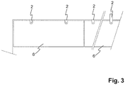
- Figure 3
- plan view of the smoke barrier system.
-
The reference symbols used in the drawings, and their meanings, are listed in summary form in the list of reference symbols. In principle, identical parts are provided with the same reference symbols in the figures.
-
Figure 1 shows an exploded view of a smoke barrier system 1. The smoke barrier system 1 comprises a bracket 2, a glass panel 6 and fastener means 3. The glass panel 6 comprises a hole 61.The bracket 2 is designed as elbow with an angle of approximately 90° between the two legs. The bracket 2 is designed such that a first leg can be fixed to the supporting construction and the other, second leg can be fastened to the hole 61 of the glass panel 6.
-
The smoke barrier system 1 further comprises a grommet 5, wherein the outer cross section of the grommet 5 essentially corresponds to the inner cross section of the hole 61. The grommet 5 is placed inside the hole 61. The grommet 5 stabilizes the fastener means 3 in the hole 61.
-
The fastener means 3 comprise a bolt 31, a nut 32 and a clamping plate 33. The nut 32 can be designed to engage with the second leg of the bracket 2. The engagement can be provide a locked orientation of the nut 32 relative to the second leg of the bracket 2. Therefore, no wrench is needed to fasten the bolt 31 to the nut 32. In another embodiment the nut 32 has to be hold by a wrench as the orientation relative to the second leg is not fixed (for example see fig. 2). The bolt 31 is placed onto the second leg of the bracket 2 and a first, intumescent washer 4 is placed on the bolt 31. The glass panel 6 with the grommet 5 in the hole 61 is arranged onto the bolt 31. Additionally, a second, intumescent washer 4 is arranged on the bolt 31 on top of the hole 61. The clamping plate 33 can be arranged on the washer 4 and the bolt 31 can be fastened to clamp the glass panel 6 between the fastener means 3 (bolt 31, nut 32 and/or clamping plate 33) and the second leg of the bracket 2. In another embodiment the bolt 31 and the clamping plate 33 can first be assembled together with the glass panel 6 and the washer 4 and afterwards be fastened to the bracket 2. The intumescent washer 4 can expand upon exposure to elevated temperature respectively upon thermal influence. Said thermal influence can originate form a fire and/or hot smoke. The term temperature influence respectively thermal influence means that the temperature of the air respectively gas is at least 80°C or higher. Under thermal influence, the washer 4 can form a thermally insulating layer. Furthermore, under thermal influence the intumescent washer 4 can build up additional pressure between the fastener means 4 and the glass panel 6. The swollen washer 4 can prevent and/or reduce the thermal load on the hole 61, the grommet 5 and/or the fastener means 3. The reduced thermal load can increase the stability of the smoke barrier system 1 in the event of a fire and/or the impact of hot gases.
-
In figure 2 assembled smoke barrier systems 1 are shown. Figure 2b depicts an assembled smoke barrier system 1 similar to the one shown in fig. 1 with a bent bracket 2.
-
The bracket 2 shown in figure 2b is designed as flat bar, wherein a first portion of the bar respectively first leg of the bar is fixed to the supporting construction. A second portion of the bar respectively second leg of the bar is fastened to the glass panel 6. Figure 2a shows a flush arrangement of the fastener means 3, wherein in figure 2b a non-flush configuration of the fastener means 3 is shown. For fastening the fastener means 3 shown in figure 2b two tool are required to each in one side of the glass panel 6 to ensure secure fastening. For the fastening of the flash arrangement (figure 2a) only one tool is needed as the nut 32 can be locked in the bracket 2. Accordingly, only the bolt 31 has to be tightened.
-
Figure 3 shows plan view of the smoke barrier system comprising at least two glass panels 6, wherein each glass panel 6 is fastened to two brackets 2. The brackets 2 are fixed to the supporting construction. The two panels 6 are arranged adjacent to each other. The adjacent panels 6 build a uniform smoke barrier system 1. The space between the adjacent panels 6 is minimized to allow minor thermal expansion of the panels 6 due to a temperature influence and to prevent the passage of fire and/or hot gas. The space can be maximum 7 mm, in particular maximum 5 mm.
-
While the invention has been described in present preferred embodiments of the invention, it is distinctly understood that the invention is not limited thereto, but may be otherwise variously embodied and practised within the scope of the claims.
-
Due to the improved stability of the smoke barrier system 1, in particular of the glass panel 6, in particular the protection of the glass panel 6 at the location of the hole 61, smoke barrier system 1 can comprise a glass panel with a size of 2x1.5 m respectively 1x1.6 m (wxh) for DH classification and 2.5x1.8 m (wxh) for D600 classification. This maximum size significantly exceeds the size of commercially glass panels 6 used in a smoke barrier system 1.