EP3348497B1 - Conveyor chain - Google Patents
Conveyor chain Download PDFInfo
- Publication number
- EP3348497B1 EP3348497B1 EP18150852.4A EP18150852A EP3348497B1 EP 3348497 B1 EP3348497 B1 EP 3348497B1 EP 18150852 A EP18150852 A EP 18150852A EP 3348497 B1 EP3348497 B1 EP 3348497B1
- Authority
- EP
- European Patent Office
- Prior art keywords
- face
- elongate pin
- elongate
- retaining member
- link
- Prior art date
- Legal status (The legal status is an assumption and is not a legal conclusion. Google has not performed a legal analysis and makes no representation as to the accuracy of the status listed.)
- Active
Links
- 230000000717 retained effect Effects 0.000 claims description 7
- 230000001419 dependent effect Effects 0.000 claims description 3
- 238000003466 welding Methods 0.000 claims description 3
- 241000237519 Bivalvia Species 0.000 claims 1
- 235000020639 clam Nutrition 0.000 claims 1
- 239000011521 glass Substances 0.000 description 7
- 230000001788 irregular Effects 0.000 description 7
- 230000000052 comparative effect Effects 0.000 description 6
- 125000006850 spacer group Chemical group 0.000 description 3
- 230000001681 protective effect Effects 0.000 description 2
- 238000000137 annealing Methods 0.000 description 1
- 238000007664 blowing Methods 0.000 description 1
- 239000003814 drug Substances 0.000 description 1
- 239000002304 perfume Substances 0.000 description 1
- 230000001012 protector Effects 0.000 description 1
Images


Classifications
-
- B—PERFORMING OPERATIONS; TRANSPORTING
- B65—CONVEYING; PACKING; STORING; HANDLING THIN OR FILAMENTARY MATERIAL
- B65G—TRANSPORT OR STORAGE DEVICES, e.g. CONVEYORS FOR LOADING OR TIPPING, SHOP CONVEYOR SYSTEMS OR PNEUMATIC TUBE CONVEYORS
- B65G17/00—Conveyors having an endless traction element, e.g. a chain, transmitting movement to a continuous or substantially-continuous load-carrying surface or to a series of individual load-carriers; Endless-chain conveyors in which the chains form the load-carrying surface
- B65G17/06—Conveyors having an endless traction element, e.g. a chain, transmitting movement to a continuous or substantially-continuous load-carrying surface or to a series of individual load-carriers; Endless-chain conveyors in which the chains form the load-carrying surface having a load-carrying surface formed by a series of interconnected, e.g. longitudinal, links, plates, or platforms
- B65G17/063—Conveyors having an endless traction element, e.g. a chain, transmitting movement to a continuous or substantially-continuous load-carrying surface or to a series of individual load-carriers; Endless-chain conveyors in which the chains form the load-carrying surface having a load-carrying surface formed by a series of interconnected, e.g. longitudinal, links, plates, or platforms the load carrying surface being formed by profiles, rods, bars, rollers or the like attached to more than one traction element
- B65G17/064—Conveyors having an endless traction element, e.g. a chain, transmitting movement to a continuous or substantially-continuous load-carrying surface or to a series of individual load-carriers; Endless-chain conveyors in which the chains form the load-carrying surface having a load-carrying surface formed by a series of interconnected, e.g. longitudinal, links, plates, or platforms the load carrying surface being formed by profiles, rods, bars, rollers or the like attached to more than one traction element the profiles, rods, bars, rollers or the like being interconnected by a mesh or grid-like structure
-
- B—PERFORMING OPERATIONS; TRANSPORTING
- B65—CONVEYING; PACKING; STORING; HANDLING THIN OR FILAMENTARY MATERIAL
- B65G—TRANSPORT OR STORAGE DEVICES, e.g. CONVEYORS FOR LOADING OR TIPPING, SHOP CONVEYOR SYSTEMS OR PNEUMATIC TUBE CONVEYORS
- B65G17/00—Conveyors having an endless traction element, e.g. a chain, transmitting movement to a continuous or substantially-continuous load-carrying surface or to a series of individual load-carriers; Endless-chain conveyors in which the chains form the load-carrying surface
- B65G17/06—Conveyors having an endless traction element, e.g. a chain, transmitting movement to a continuous or substantially-continuous load-carrying surface or to a series of individual load-carriers; Endless-chain conveyors in which the chains form the load-carrying surface having a load-carrying surface formed by a series of interconnected, e.g. longitudinal, links, plates, or platforms
- B65G17/08—Conveyors having an endless traction element, e.g. a chain, transmitting movement to a continuous or substantially-continuous load-carrying surface or to a series of individual load-carriers; Endless-chain conveyors in which the chains form the load-carrying surface having a load-carrying surface formed by a series of interconnected, e.g. longitudinal, links, plates, or platforms the surface being formed by the traction element
- B65G17/083—Conveyors having an endless traction element, e.g. a chain, transmitting movement to a continuous or substantially-continuous load-carrying surface or to a series of individual load-carriers; Endless-chain conveyors in which the chains form the load-carrying surface having a load-carrying surface formed by a series of interconnected, e.g. longitudinal, links, plates, or platforms the surface being formed by the traction element the surface being formed by profiles, rods, bars, rollers or the like
-
- B—PERFORMING OPERATIONS; TRANSPORTING
- B65—CONVEYING; PACKING; STORING; HANDLING THIN OR FILAMENTARY MATERIAL
- B65G—TRANSPORT OR STORAGE DEVICES, e.g. CONVEYORS FOR LOADING OR TIPPING, SHOP CONVEYOR SYSTEMS OR PNEUMATIC TUBE CONVEYORS
- B65G17/00—Conveyors having an endless traction element, e.g. a chain, transmitting movement to a continuous or substantially-continuous load-carrying surface or to a series of individual load-carriers; Endless-chain conveyors in which the chains form the load-carrying surface
- B65G17/30—Details; Auxiliary devices
- B65G17/38—Chains or like traction elements; Connections between traction elements and load-carriers
- B65G17/40—Chains acting as load-carriers
-
- B—PERFORMING OPERATIONS; TRANSPORTING
- B65—CONVEYING; PACKING; STORING; HANDLING THIN OR FILAMENTARY MATERIAL
- B65G—TRANSPORT OR STORAGE DEVICES, e.g. CONVEYORS FOR LOADING OR TIPPING, SHOP CONVEYOR SYSTEMS OR PNEUMATIC TUBE CONVEYORS
- B65G2201/00—Indexing codes relating to handling devices, e.g. conveyors, characterised by the type of product or load being conveyed or handled
- B65G2201/02—Articles
- B65G2201/0235—Containers
- B65G2201/0244—Bottles
-
- B—PERFORMING OPERATIONS; TRANSPORTING
- B65—CONVEYING; PACKING; STORING; HANDLING THIN OR FILAMENTARY MATERIAL
- B65G—TRANSPORT OR STORAGE DEVICES, e.g. CONVEYORS FOR LOADING OR TIPPING, SHOP CONVEYOR SYSTEMS OR PNEUMATIC TUBE CONVEYORS
- B65G2207/00—Indexing codes relating to constructional details, configuration and additional features of a handling device, e.g. Conveyors
- B65G2207/12—Chain pin retainers
Definitions
- the present invention relates to a multi-link conveyor chain which may be used (for example) in the glass industry and to a retaining member for use in the multi-link conveyor chain.
- Multi-link conveyor chains are in widespread use in the glass industry for transporting glass products between processing stations.
- a multi-link conveyor chain which is typically 100 feet long may be used to transport blown glass from a blowing station to an annealing station.
- a multi-link conveyor chain may be used to transport small glassware such as perfume bottles, wine glasses, pharmaceutical glassware and decorated medicine bottles.
- one conventional multi-link conveyor chain there is a plurality of parallel spaced apart elongate pins having an oval-shaped cross-section.
- Mounted on adjacent elongate pins are a series of link plates spaced apart along the pin by a plurality of washers, each link plate comprising a first and a second link.
- Each of the first and second links is capable of engaging a drive sprocket and has an oval-shaped aperture for receiving the elongate pin.
- the multi-link conveyor chain is driven by the engagement of the links of the link plate with the multiple teeth of a drive sprocket during a cycle of engagement.
- the conventional multi-link conveyor chain is assembled so that each end of the elongate pin extends beyond the outermost link plate (ie beyond the edge of the flat conveyor surface) and a pin head is fixed to each exposed end.
- Each end of the elongate pin is secured in a protective enclosure member (eg a head protector) that has a countersink to accommodate a pin head such that the pin head does not protrude from the enclosure member.
- a protective enclosure member eg a head protector
- the protective enclosure member is equipped with twin bores to couple adjacent elongate pins.
- US-A-4911681 discloses a multi-link conveyor chain according to the preamble of claim 1.
- WO-A-2013/029624 discloses a retaining member according to the preamble of claim 10.
- the multi-link conveyor chain known as LIFEGUARDTM is a side guide conveyor chain which deploys interlocking enclosure members to provide a gap-free side profile.
- the present invention seeks to improve multi-link conveyor chains by using single bore retaining members.
- the present invention provides a multi-link conveyor chain adapted to provide a substantially flat horizontal surface driveable between a first processing station and a second processing station by engagement with a drive sprocket, said multi-link conveyor chain comprising:
- the multi-link conveyor chain provides advantageously a continuous uninterrupted flat running surface and by virtue of the single transverse bore of the retaining members is straightforward to cut and rejoin.
- first elongate pin, second elongate pin and third elongate pin are identical.
- References to "elongate pin” herein are intended to be a reference to any of the first elongate pin, second elongate pin and third elongate pin.
- the elongate pin has a non-circular section.
- the non-circular section of the elongate pin is substantially elliptical (or oval).
- first retaining member and second retaining member are identical.
- References to "retaining member” herein are intended to be a reference to either or both of the first retaining member and second retaining member.
- the first retaining member is nested with the first adjacent first retaining member in a non-overlapping fashion.
- the first retaining member is nested with the first adjacent first retaining member in a non-interlocking fashion.
- the first adjacent first retaining member is nested with the second adjacent first retaining member in a non-overlapping fashion.
- the first adjacent first retaining member is nested with the second adjacent first retaining member in a non-interlocking fashion.
- the second retaining member is nested with the first adjacent second retaining member in a non-overlapping fashion.
- the second retaining member is nested with the first adjacent second retaining member in a non-interlocking fashion.
- the first adjacent second retaining member is nested with the second adjacent second retaining member in a non-overlapping fashion.
- the first adjacent second retaining member is nested with the second adjacent second retaining member in a non-interlocking fashion.
- the first retaining member is nested with the first adjacent first retaining member in an overlapping fashion.
- the first retaining member is nested with the first adjacent first retaining member in an interlocking fashion.
- the first adjacent first retaining member is nested with the second adjacent first retaining member in an overlapping fashion.
- the first adjacent first retaining member is nested with the second adjacent first retaining member in an interlocking fashion.
- the second retaining member is nested with the first adjacent second retaining member in an overlapping fashion.
- the second retaining member is nested with the first adjacent second retaining member in an interlocking fashion.
- the first adjacent second retaining member is nested with the second adjacent second retaining member in an overlapping fashion.
- the first adjacent second retaining member is nested with the second adjacent second retaining member in an interlocking fashion.
- the convex end face may be substantially (eg partially or fully) S-shaped.
- the S-shape may be regular or irregular.
- the concave end face may be substantially (eg partially or fully) S-shaped.
- the S-shape may be regular or irregular.
- the convex end face may be substantially (eg partially or fully) V-shaped.
- the V-shape may be regular or irregular.
- the concave end face may be substantially (eg partially or fully) V-shaped.
- the V-shape may be regular or irregular.
- the convex end face is substantially (eg partially or fully) C-shaped.
- the C-shape may be regular or irregular.
- the concave end face is substantially (eg partially or fully) C-shaped.
- the C-shape may be regular or irregular.
- the convex end face may be transverse planar or non-planar.
- the convex end face may be rectangular convex.
- the concave end face may be transverse planar or non-planar.
- the concave end face may be rectangular concave.
- the main body defines a single transverse bore which is substantially elliptical (or oval).
- the retaining member may be sized and configured so as to have a maximum radial extent which is equal to or less than the link plates. This ensures that the retaining member does not interfere with the substantially flat horizontal surface.
- the main body of the retaining member defines a single non-circular transverse bore, wherein the shape of the single non-circular transverse bore essentially matches the non-circular section of the elongate pin.
- an elongate pin is retained in the single transverse bore by an interference fit. This assists the retaining member to articulate with the elongate pin.
- the end of an elongate pin may be non-protrudingly retained in the single transverse bore.
- an elongate pin may be retained securely in the single transverse bore.
- the end of an elongate pin may be retained securely in the single transverse bore by welding (preferably laser welding).
- the end of an elongate pin may be threaded and may be retained securely in the single transverse bore by a threaded fastener.
- each of the first link and second link of the link plate defines a non-circular aperture whose shape essentially matches the non-circular section of an elongate pin.
- each of the first and the second link of a link plate defines an aperture (eg a non-circular aperture) whose shape non-identically matches the section (eg non-circular section) of the elongate pin.
- the non-identical match between the section of the elongate pin and the shape of the aperture defined by the main body of the link causes the link plate to be advantageously driven by the elongate pin throughout the cycle of engagement with the drive sprocket.
- each of the first link and second link of the link plate is substantially flat-edged.
- each of the first link and second link of the link plate has a flat-edged, substantially teardrop profile.
- Certain (eg all) link plates may be spaced apart by one or more spacers.
- the main body of the (or each) spacer may define a circular or non-circular aperture.
- each spacer comprises a main body defining a non-circular aperture for receiving the elongate pin whose shape essentially matches the non-circular section of the elongate pin.
- the non-circular aperture defined by the main body of each of the first link and second link is substantially elliptical (or oval) with an enlarged side portion.
- the enlarged side portion extends inwardly towards the connecting portion.
- the multi-link conveyor chain of the invention is suitable for use in any industry which desires transportation between a first and a second station.
- the multi-link conveyor chain of the invention could be used to transport automotive parts in the automotive industry.
- the present invention provides a retaining member for a multi-link conveyor chain as hereinbefore defined, wherein a plurality of the retaining members are suitable to be mutually spaced apart at the first edge and the second edge of the substantially flat horizontal surface adjacent to the link plates so as to enclose the first end of each of the plurality of elongate pins, wherein the retaining member comprises a main body defining a single transverse bore, wherein the shape of the single transverse bore essentially matches the section of an elongate pin and the depth of the single transverse bore is sufficient to retain the first end of an elongate pin, whereby the plurality of retaining members includes a retaining member which in use is mounted on the first elongate pin and is nested with a first adjacent retaining member mounted on the second elongate pin which is nested with a second adjacent retaining member mounted on the third elongate pin, wherein the retaining member comprises an elongate main body having an upper edge face substantially parallel to
- FIG. 1a illustrates for comparative purposes only a perspective view of a retaining member 1 which is not part of the invention.
- the retaining member 1 comprises an elongate main body 2 having an upper edge face 3 parallel to and spaced apart from a lower edge face 4.
- the upper edge face 3 and lower edge face 4 are connected at a leading end by a convex end face 6 and at a trailing end by a concave end face 7.
- the convex end face 6 and concave end face 7 are complementarily C-shaped.
- the main body 2 defines a single transverse bore 5 which is elliptical.
- Figure 1b illustrates for comparative purposes only a perspective view of a retaining member 100 which is not part of the invention.
- the retaining member 100 is largely identical to the retaining member 1 but the upper edge face 30 and lower edge face 40 are longer than the upper edge face 3 and lower edge face 4 and facilitate use of the retaining member 100 in a multi-link conveyor chain with an extended pitch.
- FIG. 1c illustrates for comparative purposes only a perspective view of a retaining member 31 which is not part of the invention.
- the retaining member 31 comprises an elongate main body 32 having an upper edge face 33 parallel to and spaced apart from a lower edge face 34.
- the upper edge face 33 and lower edge face 34 are connected at a leading end by a convex end face 36 and at a trailing end by a concave end face 37.
- the convex end face 36 and concave end face 37 are complementarily-shaped.
- the convex end face 36 has a regular C-shape whereas the concave end face 37 has an irregular S-shape.
- the main body 32 defines a single transverse bore 35 which is elliptical.
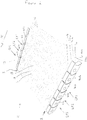
- FIG. 2 illustrates for comparative purposes only in partial view a multi-link conveyor chain designated generally by reference numeral 11 which is not part of the invention.
- the multi-link conveyor chain 11 provides a flat surface 12 upon which may be carried articles such as glass bottles in a direction of transport X to a processing station.
- the multi-link conveyor chain 11 comprises a plurality of elongate pins of elliptical section upon which are mounted a plurality of planar link plates 14.
- the plurality of elongate pins is omitted from Figure 2 .
- the elongate pins are mutually spaced apart in a substantially parallel relationship and consist of multiple triplets of elongate pins, each triplet being a first elongate pin adjacent to a second elongate pin adjacent to a third elongate pin.
- Consecutive link plates (16, 17 and 18 for example) are mounted interdigitally in a staggered fashion along one of the triplets of elongate pins (for example a first elongate pin (not illustrated but positioned at EP1), second elongate pin (not illustrated but positioned at EP2) and third elongate pin (not illustrated but positioned at EP3)).
- elongate pins for example a first elongate pin (not illustrated but positioned at EP1), second elongate pin (not illustrated but positioned at EP2) and third elongate pin (not illustrated but positioned at EP3)).
- Each of the plurality of link plates 14 has twin links 14a, 14b having a substantially teardrop profile which extends into a flat-edged, sprocket engaging tooth 14c.
- Each link 14a, 14b is connected by a connecting portion 320.
- a non-circular aperture 30 in each of links 14a, 14b non-identically matches the elliptical section of an elongate pin.
- the aperture 30 is substantially elliptical with an enlarged side portion 30a extending inwardly towards connecting portion 320.
- a first retaining member 40 of a plurality of identical mutually spaced apart first retaining members 40, 40a, 40b, 40c is positioned at the first edge A of the flat surface 12 adjacent to the link plates 14.
- the first retaining member 40 is of the type described hereinbefore with reference to Figure 1a .
- the convex end face 6 of the first retaining member 40 nests with the concave end face 7 of a first adjacent first retaining member 40a.
- the convex end face 6 of the first adjacent first retaining member 40a nests with the concave end face 7 of the second adjacent first retaining member 40c.
- a second retaining member 41 of a plurality of identical mutually spaced apart second retaining members 41, 41a, 41b, 41c is positioned at the second edge B of the flat surface 12 adjacent to the link plates 14.
- the plurality of second retaining members 41, 41a, 41b, 41c is identical to the plurality of first retaining members 40, 40a, 40b, 40c.
- the first retaining member 40 and second retaining member 41 are mounted on the first elongate pin (not illustrated but positioned at EP1).
- the first adjacent first retaining member 40a and first adjacent second retaining member 41a are mounted on the second elongate pin (not illustrated but positioned at EP2).
- the second adjacent first retaining member 40c and second adjacent second retaining member 41c are mounted on the third elongate pin (not illustrated but positioned at EP3).
- the single transverse bore 5 is an interference fit with the elongate pin which causes the retaining member to articulate with the elongate pin.
- the retaining member is laser-welded to the elongate pin.
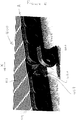
- FIGS 3(a) and (b) illustrate respectively opposite end views of a retaining member 300 according to a first embodiment of the invention.
- the retaining member 300 comprises an elongate main body 302 having an upper edge face 303 parallel to and spaced apart from a lower edge face 304.
- the upper edge face 303 and lower edge face 304 are connected at a leading end by a convex end face 306 and at a trailing end by a concave end face 3C7.
- the convex end face 306 is bifurcated to form a pair of convex end face sections 312 and 313.
- the concave end face 3C7 is bifurcated to form a pair of concave end face sections 310, 311.
- the concave end face section 310 complements the convex end face section 313 and the concave end face section 311 complements the convex end face section 312.
- the main body 302 defines a single transverse bore 305 which is elliptical.
- Figure 4 illustrates in partial view a first embodiment of the multi-link conveyor chain of the invention designated generally by reference numeral 400.
- the multi-link conveyor chain 400 provides a flat surface 412 upon which may be carried articles such as glass bottles in a direction of transport X to a processing station.
- the multi-link conveyor chain 400 comprises a plurality of elongate pins 420 of elliptical section upon which are mounted a plurality of planar link plates 414.
- the elongate pins 420 are mutually spaced apart in a substantially parallel relationship and consist of multiple triplets of elongate pins, each triplet being a first elongate pin adjacent to a second elongate pin adjacent to a third elongate pin.
- the link plates 414 are identical to those of the first embodiment described hereinbefore with reference to Figure 2 and are mounted interdigitally in a staggered fashion along one of the triplets of elongate pins in the same way.
- a first retaining member 440 of a plurality of identical mutually spaced apart first retaining members 440, 440a, 440b, 440c is shown detached from its working position at the first edge A of the flat surface 412 adjacent to the link plates 414.
- the first retaining member 440 is of the type described hereinbefore with reference to Figure 3a and 3b .
- the bifurcated convex end face 406 of the first retaining member 440 nests with the bifurcated concave end face 407 of a first adjacent first retaining member 440a.
- the bifurcated convex end face 406 of the first adjacent first retaining member 440a nests with the bifurcated concave end face 407 of the second adjacent first retaining member 440c.
- the pair of convex end face sections complements the pair of convex end face sections.
- a plurality of mutually spaced apart second retaining members (not shown) identical to the plurality of first retaining members 40, 40a, 40b, 40c is positioned adjacent to the link plates 414 at the second edge of the flat surface 412 opposite to the first edge A.
Landscapes
- Engineering & Computer Science (AREA)
- Mechanical Engineering (AREA)
- Chain Conveyers (AREA)
Description
- The present invention relates to a multi-link conveyor chain which may be used (for example) in the glass industry and to a retaining member for use in the multi-link conveyor chain.
- Multi-link conveyor chains are in widespread use in the glass industry for transporting glass products between processing stations. For example, a multi-link conveyor chain which is typically 100 feet long may be used to transport blown glass from a blowing station to an annealing station. A multi-link conveyor chain may be used to transport small glassware such as perfume bottles, wine glasses, pharmaceutical glassware and decorated medicine bottles.
- In one conventional multi-link conveyor chain, there is a plurality of parallel spaced apart elongate pins having an oval-shaped cross-section. Mounted on adjacent elongate pins are a series of link plates spaced apart along the pin by a plurality of washers, each link plate comprising a first and a second link. Each of the first and second links is capable of engaging a drive sprocket and has an oval-shaped aperture for receiving the elongate pin. The multi-link conveyor chain is driven by the engagement of the links of the link plate with the multiple teeth of a drive sprocket during a cycle of engagement. The conventional multi-link conveyor chain is assembled so that each end of the elongate pin extends beyond the outermost link plate (ie beyond the edge of the flat conveyor surface) and a pin head is fixed to each exposed end. Each end of the elongate pin is secured in a protective enclosure member (eg a head protector) that has a countersink to accommodate a pin head such that the pin head does not protrude from the enclosure member. One such arrangement is described in
EP-A-1241117 . - In the arrangement described in
EP-A-1241117 and in other conventional arrangements described in inter aliaEP-A-2368816 ,WO-A-2004/043833 ,US-A-2009/242360 ,US-A-2009/277758 ,US-A-5957268 ,DE1044707 andUS-A-6036002 , the protective enclosure member is equipped with twin bores to couple adjacent elongate pins. - Other conventional arrangements are described in
DE1807180 ,US-A-4911681 ,WO-A-2013/029624 ,EP-A-2275367 andDE-8915287U .US-A-4911681 discloses a multi-link conveyor chain according to the preamble of claim 1. -
WO-A-2013/029624 discloses a retaining member according to the preamble of claim 10. The multi-link conveyor chain known as LIFEGUARD™ is a side guide conveyor chain which deploys interlocking enclosure members to provide a gap-free side profile. - The present invention seeks to improve multi-link conveyor chains by using single bore retaining members.
- Thus viewed from one aspect the present invention provides a multi-link conveyor chain adapted to provide a substantially flat horizontal surface driveable between a first processing station and a second processing station by engagement with a drive sprocket, said multi-link conveyor chain comprising:
- a plurality of elongate pins spaced apart in substantially parallel relationship consisting of multiple triplets of elongate pins being a first elongate pin adjacent to a second elongate pin adjacent to a third elongate pin,
- wherein the first elongate pin has a first end extending beyond a first edge of the substantially flat horizontal surface and a second end extending beyond a second edge of the substantially flat horizontal surface,
- wherein the second elongate pin has a first end extending beyond a first edge of the substantially flat horizontal surface and a second end extending beyond a second edge of the substantially flat horizontal surface,
- wherein the third elongate pin has a first end extending beyond the first edge of the substantially flat horizontal surface and a second end extending beyond the second edge of the substantially flat horizontal surface;
- a plurality of substantially planar link plates each having a first link connected to a second link by a connecting portion, wherein each of the first link and the second link has a main body and a circumferentially dependent sprocket engaging member, wherein the main body defines an aperture whose shape essentially matches the section of an elongate pin whereby the plurality of substantially planar link plates is consecutively mounted interdigitally in a staggered relationship on the triplets of elongate pins;
- a plurality of first retaining members mutually spaced apart at the first edge of the substantially flat horizontal surface adjacent to the link plates so as to enclose the first end of each of the plurality of elongate pins, wherein each of the first retaining members comprises a main body defining a single transverse bore, wherein the shape of the single transverse bore essentially matches the section of an elongate pin and the depth of the single transverse bore is sufficient to retain the first end of an elongate pin whereby the plurality of first retaining members includes a first retaining member mounted on the first elongate pin which is nested with a first adjacent first retaining member mounted on the second elongate pin which is nested with a second adjacent first retaining member mounted on the third elongate pin; and
- a plurality of second retaining members mutually spaced apart at the second edge of the substantially flat horizontal surface adjacent to the link plates so as to enclose the second end of each of the plurality of elongate pins, wherein each of the second retaining members comprises a main body defining a single transverse bore, wherein the shape of the single transverse bore essentially matches the section of an elongate pin and the depth of the single transverse bore is sufficient to retain the second end of an elongate pin whereby the plurality of second retaining members includes a second retaining member mounted on the first elongate pin which is nested with a first adjacent second retaining member mounted on the second elongate pin which is nested with a second adjacent second retaining member mounted on the third elongate pin,
- wherein each retaining member comprises an elongate main body having an upper edge face substantially parallel to a lower edge face, wherein the upper edge face and lower edge face are connected at a leading end by a convex end face and at a trailing end by a concave end face, wherein the convex end face and concave end face are complementarily-shaped to facilitate nesting, wherein the convex end face is bifurcated to form a pair of convex end face sections and the concave end face is bifurcated to form a pair of concave end face sections, wherein the pair of convex end face sections and the pair of concave end face sections are complementarily-shaped to facilitate nesting.
- The multi-link conveyor chain provides advantageously a continuous uninterrupted flat running surface and by virtue of the single transverse bore of the retaining members is straightforward to cut and rejoin.
- Typically the first elongate pin, second elongate pin and third elongate pin are identical. References to "elongate pin" herein are intended to be a reference to any of the first elongate pin, second elongate pin and third elongate pin.
- Preferably the elongate pin has a non-circular section. Particularly preferably the non-circular section of the elongate pin is substantially elliptical (or oval).
- Typically the first retaining member and second retaining member are identical. References to "retaining member" herein are intended to be a reference to either or both of the first retaining member and second retaining member.
- Preferably the first retaining member is nested with the first adjacent first retaining member in a non-overlapping fashion. Preferably the first retaining member is nested with the first adjacent first retaining member in a non-interlocking fashion. Preferably the first adjacent first retaining member is nested with the second adjacent first retaining member in a non-overlapping fashion. Preferably the first adjacent first retaining member is nested with the second adjacent first retaining member in a non-interlocking fashion.
- Preferably the second retaining member is nested with the first adjacent second retaining member in a non-overlapping fashion. Preferably the second retaining member is nested with the first adjacent second retaining member in a non-interlocking fashion. Preferably the first adjacent second retaining member is nested with the second adjacent second retaining member in a non-overlapping fashion. Preferably the first adjacent second retaining member is nested with the second adjacent second retaining member in a non-interlocking fashion.
- Preferably the first retaining member is nested with the first adjacent first retaining member in an overlapping fashion. Preferably the first retaining member is nested with the first adjacent first retaining member in an interlocking fashion. Preferably the first adjacent first retaining member is nested with the second adjacent first retaining member in an overlapping fashion. Preferably the first adjacent first retaining member is nested with the second adjacent first retaining member in an interlocking fashion.
- Preferably the second retaining member is nested with the first adjacent second retaining member in an overlapping fashion. Preferably the second retaining member is nested with the first adjacent second retaining member in an interlocking fashion. Preferably the first adjacent second retaining member is nested with the second adjacent second retaining member in an overlapping fashion. Preferably the first adjacent second retaining member is nested with the second adjacent second retaining member in an interlocking fashion.
- The convex end face may be substantially (eg partially or fully) S-shaped. The S-shape may be regular or irregular.
- The concave end face may be substantially (eg partially or fully) S-shaped. The S-shape may be regular or irregular.
- The convex end face may be substantially (eg partially or fully) V-shaped. The V-shape may be regular or irregular. The concave end face may be substantially (eg partially or fully) V-shaped. The V-shape may be regular or irregular.
- Preferably the convex end face is substantially (eg partially or fully) C-shaped. The C-shape may be regular or irregular.
- Preferably the concave end face is substantially (eg partially or fully) C-shaped. The C-shape may be regular or irregular.
- The convex end face may be transverse planar or non-planar. The convex end face may be rectangular convex.
- The concave end face may be transverse planar or non-planar. The concave end face may be rectangular concave.
- Typically the main body defines a single transverse bore which is substantially elliptical (or oval).
- The retaining member may be sized and configured so as to have a maximum radial extent which is equal to or less than the link plates. This ensures that the retaining member does not interfere with the substantially flat horizontal surface.
- Preferably the main body of the retaining member defines a single non-circular transverse bore, wherein the shape of the single non-circular transverse bore essentially matches the non-circular section of the elongate pin.
- Preferably the end of an elongate pin is retained in the single transverse bore by an interference fit. This assists the retaining member to articulate with the elongate pin. The end of an elongate pin may be non-protrudingly retained in the single transverse bore.
- The end of an elongate pin may be retained securely in the single transverse bore. For example, the end of an elongate pin may be retained securely in the single transverse bore by welding (preferably laser welding). Alternatively the end of an elongate pin may be threaded and may be retained securely in the single transverse bore by a threaded fastener.
- Preferably the main body of each of the first link and second link of the link plate defines a non-circular aperture whose shape essentially matches the non-circular section of an elongate pin.
- Preferably the main body of each of the first and the second link of a link plate defines an aperture (eg a non-circular aperture) whose shape non-identically matches the section (eg non-circular section) of the elongate pin. The non-identical match between the section of the elongate pin and the shape of the aperture defined by the main body of the link causes the link plate to be advantageously driven by the elongate pin throughout the cycle of engagement with the drive sprocket.
- In a preferred embodiment, the circumferentially dependent sprocket engaging member of each of the first link and second link of the link plate is substantially flat-edged. Preferably each of the first link and second link of the link plate has a flat-edged, substantially teardrop profile. Certain (eg all) link plates may be spaced apart by one or more spacers. The main body of the (or each) spacer may define a circular or non-circular aperture. In a preferred embodiment of the invention, each spacer comprises a main body defining a non-circular aperture for receiving the elongate pin whose shape essentially matches the non-circular section of the elongate pin.
- Preferably the non-circular aperture defined by the main body of each of the first link and second link is substantially elliptical (or oval) with an enlarged side portion. Particularly preferably the enlarged side portion extends inwardly towards the connecting portion.
- The multi-link conveyor chain of the invention is suitable for use in any industry which desires transportation between a first and a second station. For example, the multi-link conveyor chain of the invention could be used to transport automotive parts in the automotive industry.
- Viewed from a further aspect the present invention provides a retaining member for a multi-link conveyor chain as hereinbefore defined,
wherein a plurality of the retaining members are suitable to be mutually spaced apart at the first edge and the second edge of the substantially flat horizontal surface adjacent to the link plates so as to enclose the first end of each of the plurality of elongate pins,
wherein the retaining member comprises a main body defining a single transverse bore,
wherein the shape of the single transverse bore essentially matches the section of an elongate pin and the depth of the single transverse bore is sufficient to retain the first end of an elongate pin,
whereby the plurality of retaining members includes a retaining member which in use is mounted on the first elongate pin and is nested with a first adjacent retaining member mounted on the second elongate pin which is nested with a second adjacent retaining member mounted on the third elongate pin,
wherein the retaining member comprises an elongate main body having an upper edge face substantially parallel to a lower edge face,
wherein the upper edge face and lower edge face are connected at a leading end by a convex end face and at a trailing end by a concave end face,
wherein the convex end face and concave end face are complementarily-shaped to facilitate nesting,
characterised in that the convex end face is bifurcated to form a pair of convex end face sections and the concave end face is bifurcated to form a pair of concave end face sections and in that the pair of convex end face sections and the pair of concave end face sections are complementarily-shaped to facilitate nesting. - The present invention will now be described in a non-limitative sense with reference to the accompanying Figures in which:
-
Figures 1a-c illustrate for comparative purposes only a perspective view of certain retaining members which are not part of the invention; -
Figure 2 illustrates for comparative purposes only in partial view a multi-link conveyor chain which is not part of the invention; -
Figures 3(a) and (b) illustrate respectively opposite end views of a retaining member according to a first embodiment of the invention; and -
Figure 4 illustrates in partial view a multi-link conveyor chain according to a first embodiment of the invention. -
Figure 1a illustrates for comparative purposes only a perspective view of a retaining member 1 which is not part of the invention. The retaining member 1 comprises an elongatemain body 2 having anupper edge face 3 parallel to and spaced apart from alower edge face 4. Theupper edge face 3 andlower edge face 4 are connected at a leading end by a convex end face 6 and at a trailing end by aconcave end face 7. The convex end face 6 andconcave end face 7 are complementarily C-shaped. Themain body 2 defines a singletransverse bore 5 which is elliptical. -
Figure 1b illustrates for comparative purposes only a perspective view of a retainingmember 100 which is not part of the invention. The retainingmember 100 is largely identical to the retaining member 1 but theupper edge face 30 andlower edge face 40 are longer than theupper edge face 3 andlower edge face 4 and facilitate use of the retainingmember 100 in a multi-link conveyor chain with an extended pitch. -
Figure 1c illustrates for comparative purposes only a perspective view of a retainingmember 31 which is not part of the invention. The retainingmember 31 comprises an elongatemain body 32 having an upper edge face 33 parallel to and spaced apart from alower edge face 34. Theupper edge face 33 andlower edge face 34 are connected at a leading end by aconvex end face 36 and at a trailing end by aconcave end face 37. Theconvex end face 36 andconcave end face 37 are complementarily-shaped. Theconvex end face 36 has a regular C-shape whereas theconcave end face 37 has an irregular S-shape. Themain body 32 defines a single transverse bore 35 which is elliptical. -
Figure 2 illustrates for comparative purposes only in partial view a multi-link conveyor chain designated generally byreference numeral 11 which is not part of the invention. Themulti-link conveyor chain 11 provides aflat surface 12 upon which may be carried articles such as glass bottles in a direction of transport X to a processing station. - The
multi-link conveyor chain 11 comprises a plurality of elongate pins of elliptical section upon which are mounted a plurality ofplanar link plates 14. For the sake of clarity, the plurality of elongate pins is omitted fromFigure 2 . However the elongate pins are mutually spaced apart in a substantially parallel relationship and consist of multiple triplets of elongate pins, each triplet being a first elongate pin adjacent to a second elongate pin adjacent to a third elongate pin. Consecutive link plates (16, 17 and 18 for example) are mounted interdigitally in a staggered fashion along one of the triplets of elongate pins (for example a first elongate pin (not illustrated but positioned at EP1), second elongate pin (not illustrated but positioned at EP2) and third elongate pin (not illustrated but positioned at EP3)). - Each of the plurality of
link plates 14 has twin links 14a, 14b having a substantially teardrop profile which extends into a flat-edged, sprocket engaging tooth 14c. Each link 14a, 14b is connected by a connectingportion 320. Anon-circular aperture 30 in each of links 14a, 14b non-identically matches the elliptical section of an elongate pin. Theaperture 30 is substantially elliptical with an enlarged side portion 30a extending inwardly towards connectingportion 320. - A first retaining
member 40 of a plurality of identical mutually spaced apart first retainingmembers flat surface 12 adjacent to thelink plates 14. The first retainingmember 40 is of the type described hereinbefore with reference toFigure 1a . The convex end face 6 of the first retainingmember 40 nests with theconcave end face 7 of a first adjacent first retainingmember 40a. The convex end face 6 of the first adjacent first retainingmember 40a nests with theconcave end face 7 of the second adjacent first retaining member 40c. - A second retaining
member 41 of a plurality of identical mutually spaced apart second retainingmembers flat surface 12 adjacent to thelink plates 14. The plurality ofsecond retaining members members - The first retaining
member 40 and second retainingmember 41 are mounted on the first elongate pin (not illustrated but positioned at EP1). The first adjacent first retainingmember 40a and first adjacent second retainingmember 41a are mounted on the second elongate pin (not illustrated but positioned at EP2). The second adjacent first retaining member 40c and second adjacent second retaining member 41c are mounted on the third elongate pin (not illustrated but positioned at EP3). In each case, the singletransverse bore 5 is an interference fit with the elongate pin which causes the retaining member to articulate with the elongate pin. In each case, the retaining member is laser-welded to the elongate pin. -
Figures 3(a) and (b) illustrate respectively opposite end views of a retainingmember 300 according to a first embodiment of the invention. The retainingmember 300 comprises an elongatemain body 302 having anupper edge face 303 parallel to and spaced apart from a lower edge face 304. Theupper edge face 303 and lower edge face 304 are connected at a leading end by aconvex end face 306 and at a trailing end by a concave end face 3C7. Theconvex end face 306 is bifurcated to form a pair of convexend face sections end face sections end face section 310 complements the convexend face section 313 and the concaveend face section 311 complements the convexend face section 312. Themain body 302 defines a singletransverse bore 305 which is elliptical. -
Figure 4 illustrates in partial view a first embodiment of the multi-link conveyor chain of the invention designated generally byreference numeral 400. Themulti-link conveyor chain 400 provides aflat surface 412 upon which may be carried articles such as glass bottles in a direction of transport X to a processing station. - The
multi-link conveyor chain 400 comprises a plurality ofelongate pins 420 of elliptical section upon which are mounted a plurality ofplanar link plates 414. The elongate pins 420 are mutually spaced apart in a substantially parallel relationship and consist of multiple triplets of elongate pins, each triplet being a first elongate pin adjacent to a second elongate pin adjacent to a third elongate pin. Thelink plates 414 are identical to those of the first embodiment described hereinbefore with reference toFigure 2 and are mounted interdigitally in a staggered fashion along one of the triplets of elongate pins in the same way. - A first retaining
member 440 of a plurality of identical mutually spaced apart first retainingmembers flat surface 412 adjacent to thelink plates 414. Thefirst retaining member 440 is of the type described hereinbefore with reference toFigure 3a and 3b . The bifurcatedconvex end face 406 of the first retainingmember 440 nests with the bifurcatedconcave end face 407 of a first adjacent first retaining member 440a. The bifurcatedconvex end face 406 of the first adjacent first retaining member 440a nests with the bifurcatedconcave end face 407 of the second adjacent first retainingmember 440c. In each case, the pair of convex end face sections complements the pair of convex end face sections. - A plurality of mutually spaced apart second retaining members (not shown) identical to the plurality of first retaining
members link plates 414 at the second edge of theflat surface 412 opposite to the first edge A.
Claims (10)
- A multi-link conveyor chain (400) adapted to provide a substantially flat horizontal surface (412) driveable between a first processing station and a second processing station by engagement with a drive sprocket, said multi-link conveyor chain (400) comprising:a plurality of elongate pins (420) spaced apart in substantially parallel relationship consisting of multiple triplets of elongate pins being a first elongate pin adjacent to a second elongate pin adjacent to a third elongate pin,wherein the first elongate pin has a first end extending beyond a first edge of the substantially flat horizontal surface and a second end extending beyond a second edge of the substantially flat horizontal surface,wherein the second elongate pin has a first end extending beyond a first edge of the substantially flat horizontal surface and a second end extending beyond a second edge of the substantially flat horizontal surface,wherein the third elongate pin has a first end extending beyond the first edge of the substantially flat horizontal surface and a second end extending beyond the second edge of the substantially flat horizontal surface;a plurality of substantially planar link plates (14, 414) each having a first link (14a) connected to a second link (14b) by a connecting portion, wherein each of the first link (14a) and the second link (14b) has a main body and a circumferentially dependent sprocket engaging member (14c), wherein the main body defines an aperture (30) whose shape essentially matches the section of an elongate pin (420) whereby the plurality of substantially planar link plates (14, 414) is consecutively mounted interdigitally in a staggered relationship on the triplets of elongate pins;a plurality of first retaining members (300, 440, 440a, 440b, 440c) mutually spaced apart at the first edge of the substantially flat horizontal surface adjacent to the link plates (414) so as to enclose the first end of each of the plurality of elongate pins (420), wherein each of the first retaining members (300, 440, 440a, 440b, 440c) comprises a main body (302) defining a single transverse bore (305), wherein the shape of the single transverse bore (305) essentially matches the section of an elongate pin (420) and the depth of the single transverse bore (305) is sufficient to retain the first end of an elongate pin (420) whereby the plurality of first retaining members (300, 440, 440a, 440b, 440c) includes a first retaining member mounted on the first elongate pin which is nested with a first adjacent first retaining member mounted on the second elongate pin which is nested with a second adjacent first retaining member mounted on the third elongate pin; anda plurality of second retaining members mutually spaced apart at the second edge of the substantially flat horizontal surface adjacent to the link plates so as to enclose the second end of each of the plurality of elongate pins, wherein each of the second retaining members comprises a main body defining a single transverse bore, wherein the shape of the single transverse bore essentially matches the section of an elongate pin and the depth of the single transverse bore is sufficient to retain the second end of an elongate pin whereby the plurality of second retaining members includes a second retaining member mounted on the first elongate pin which is nested with a first adjacent second retaining member mounted on the second elongate pin which is nested with a second adjacent second retaining member mounted on the third elongate pin,
characterised in that each retaining member (300, 440, 440a, 440b, 440c) comprises an elongate main body (302) having an upper edge face (303) substantially parallel to a lower edge face (304), wherein the upper edge face (303) and lower edge face (304) are connected at a leading end by a convex end face (306, 406) and at a trailing end by a concave end face (307, 407), wherein the convex end face (306, 406) and concave end face (307, 407) are complementarily-shaped to facilitate nesting, wherein the convex end face (306, 406) is bifurcated to form a pair of convex end face sections (312, 313) and the concave end face (307, 407) is bifurcated to form a pair of concave end face sections (310, 311), wherein the pair of convex end face sections (312, 313) and the pair of concave end face sections (310, 311) are complementarily-shaped to facilitate nesting. - A multi-link conveyor chain as claimed in claim 1 wherein the section of the elongate pin (420) is substantially elliptical.
- A multi-link conveyor chain as claimed in claim 1 wherein the convex end face (306, 406) is substantially C-shaped.
- A multi-link conveyor chain as claimed in claim 1 wherein the concave end face (307, 407) is substantially S-shaped.
- A multi-link conveyor chain as claimed in claim 1 wherein the concave end face (307, 407) is substantially C-shaped.
- A multi-link conveyor chain as claimed in any preceding claim wherein the main body (302) defines a single transverse bore (305) which is substantially elliptical.
- A multi-link conveyor chain as claimed in any preceding claim wherein the end of an elongate pin (420) is retained in the single transverse bore (305) by an interference fit.
- A multi-link conveyor chain as claimed in any preceding claim wherein the end of an elongate pin (420) is retained securely in the single transverse bore (305) by laser welding.
- A multi-link conveyor chain as claimed in any preceding claim wherein the main body of each of the first link (14A) and second link (14B) of the link plate (14, 414) defines a non-circular aperture (30) whose shape matches the non-circular section of an elongate pin (420).
- A retaining member (300, 440, 440a, 440b, 440c) for a multi-link conveyor chain as defined in any of clams 1 to 9,
wherein a plurality of the retaining members (300, 440, 440a, 440b, 440c) are suitable to be mutually spaced apart at the first edge and the second edge of the substantially flat horizontal surface adjacent to the link plates (414) so as to enclose the first end of each of the plurality of elongate pins (420),
wherein the retaining member (300, 440, 440a, 440b, 440c) comprises a main body (302) defining a single transverse bore (305),
wherein the shape of the single transverse bore (305) essentially matches the section of an elongate pin (420) and the depth of the single transverse bore (305) is sufficient to retain the first end of an elongate pin (420),
whereby the plurality of retaining members (300, 440, 440a, 440b, 440c) includes a retaining member which in use is mounted on the first elongate pin and is nested with a first adjacent retaining member mounted on the second elongate pin which is nested with a second adjacent retaining member mounted on the third elongate pin,
wherein the retaining member (300, 440, 440a, 440b, 440c) comprises an elongate main body (302) having an upper edge face (303) substantially parallel to a lower edge face (304),
wherein the upper edge face (303) and lower edge face (304) are connected at a leading end by a convex end face (306, 406) and at a trailing end by a concave end face (307, 407),
wherein the convex end face (306, 406) and concave end face (307, 407) are complementarily-shaped to facilitate nesting,
characterised in that the convex end face (306, 406) is bifurcated to form a pair of convex end face sections (312, 313) and the concave end face (307, 407) is bifurcated to form a pair of concave end face sections (310, 311) and in that the pair of convex end face sections (312, 313) and the pair of concave end face sections (310, 311) are complementarily-shaped to facilitate nesting.
Applications Claiming Priority (2)
| Application Number | Priority Date | Filing Date | Title |
|---|---|---|---|
| GBGB1700441.7A GB201700441D0 (en) | 2017-01-11 | 2017-01-11 | Conveyor chain |
| GBGB1707601.9A GB201707601D0 (en) | 2017-05-12 | 2017-05-12 | Conveyor chain |
Publications (2)
| Publication Number | Publication Date |
|---|---|
| EP3348497A1 EP3348497A1 (en) | 2018-07-18 |
| EP3348497B1 true EP3348497B1 (en) | 2020-06-24 |
Family
ID=60953729
Family Applications (1)
| Application Number | Title | Priority Date | Filing Date |
|---|---|---|---|
| EP18150852.4A Active EP3348497B1 (en) | 2017-01-11 | 2018-01-09 | Conveyor chain |
Country Status (2)
| Country | Link |
|---|---|
| US (1) | US10358293B2 (en) |
| EP (1) | EP3348497B1 (en) |
Family Cites Families (51)
| Publication number | Priority date | Publication date | Assignee | Title |
|---|---|---|---|---|
| US1529243A (en) * | 1924-01-30 | 1925-03-10 | Libbey Owens Sheet Glass Co | Flattening table for continuous sheet glass |
| DE1044707B (en) | 1956-04-26 | 1958-11-20 | Moebelfabrik Westfalia H Rottm | Endless transport chain, especially for feeding veneer waste wood to cutting machines |
| US2986387A (en) * | 1956-06-27 | 1961-05-30 | Cambridge Tile & Mfg Company | Ceramic belt |
| DE1807180U (en) | 1959-11-18 | 1960-03-03 | Wanson Waermetechnik G M B H D | INTAKE AIR CLEANING FILTER FOR OIL FIRED RECIRCULATION HEATERS. |
| US3160264A (en) * | 1963-01-16 | 1964-12-08 | Delmar H Raybould | Conveyor chain |
| US3315791A (en) * | 1965-10-20 | 1967-04-25 | Braco Inc | Connecting link structure for conveyor |
| FR1574677A (en) * | 1967-11-06 | 1969-07-18 | ||
| CH515835A (en) | 1970-04-24 | 1971-11-30 | Gebr Hennig Gmbh | Link track |
| FR2404583A1 (en) | 1977-09-30 | 1979-04-27 | Manurhin | ENDLESS CHAIN FOR THE TRANSPORT OF PRODUCTS, ESPECIALLY ON A CONTINUOUS KINEMATIC PRODUCT PROCESSING PLANT |
| ZA818197B (en) | 1980-12-09 | 1982-10-27 | Scapa Porritt Ltd | Edge guard means for a link belt and a link belt embodying such means |
| DK148736C (en) | 1981-12-09 | 1986-03-03 | Alfa Laval Separation As | TRANSPORT SEAL, NAME FOR A DECANTER CENTER |
| JPH0621606B2 (en) | 1986-03-28 | 1994-03-23 | 株式会社椿本チエイン | Push chain |
| CA1309054C (en) * | 1987-04-15 | 1992-10-20 | William G. Hodlewsky | Conveyor chain assembly |
| US4911681A (en) * | 1989-07-17 | 1990-03-27 | Ashworth Brothers, Inc. | Ceramic conveyor belt connector rod end fixation |
| US4951457A (en) | 1989-11-08 | 1990-08-28 | Deal Douglas O | Narrow pitch articulated chain and links therefor |
| DE8915287U1 (en) * | 1989-12-30 | 1990-03-29 | NIKO Nahrungsmittel-Maschinen GmbH & Co KG, 41334 Nettetal | Conveyors, especially for fruit, vegetables or parts thereof |
| US5042244A (en) | 1990-05-21 | 1991-08-27 | Drives-Incorporated | Roof top chain |
| US5197593A (en) * | 1992-02-10 | 1993-03-30 | Ashworth Bros., Inc. | Rod and edge link fixation for conveyor belts |
| JP2551150Y2 (en) | 1993-07-13 | 1997-10-22 | 株式会社椿本チエイン | Conveyor belt that can be expanded and widened |
| IT234202Y1 (en) | 1994-11-08 | 2000-02-23 | Regina Sud Spa | CHAIN CONVEYOR WITH IMPROVED SLIDING FEATURES |
| JP3343753B2 (en) | 1995-02-27 | 2002-11-11 | 大同工業株式会社 | Chain cover |
| NL1000241C2 (en) | 1995-04-27 | 1996-10-29 | Metaalgaasweverij Twente B V | Conveyor belt. |
| US5678683A (en) | 1996-02-05 | 1997-10-21 | Rexnord Corporation | Conveyor chain with sealed plug hinge pin retention system |
| GB2309062B (en) | 1996-02-06 | 1998-01-14 | Baeltix Maskinfabrikken As | Chain link conveyor |
| JP3642629B2 (en) | 1996-05-24 | 2005-04-27 | 株式会社小林製作所 | Plastic conveyor belt and conveyor device using the same |
| DE19702005A1 (en) | 1997-01-22 | 1998-07-23 | Goro Sa | Clutch rod |
| NL1008343C2 (en) | 1998-02-18 | 1999-08-19 | Mcc Nederland | Module with retaining element for use in a modular transport mat. |
| DE29807758U1 (en) | 1998-04-29 | 1999-09-09 | Joh. Winklhofer & Söhne GmbH und Co KG, 81369 München | Apron chain |
| JP2951316B1 (en) | 1998-05-29 | 1999-09-20 | 株式会社椿本チエイン | Conveyor chain made of synthetic resin |
| DE19983305T1 (en) | 1998-06-18 | 2001-07-26 | Interlock Group Ltd | Multi-part connector |
| US6247582B1 (en) | 1998-12-21 | 2001-06-19 | Rexnord Corporation | Fiber filled chain link for a modular conveyer chain |
| JP3331464B2 (en) | 1999-03-25 | 2002-10-07 | 山久チヱイン株式会社 | Detachment device for connecting pin in synthetic resin conveyor chain |
| GB0106190D0 (en) | 2001-03-14 | 2001-05-02 | Pennine Ind Equipment Ltd | Enclosure member |
| US6854590B2 (en) | 2001-07-24 | 2005-02-15 | Fmc Technologies, Inc. | Conveyor belt assembly |
| ITMI20010599U1 (en) | 2001-11-13 | 2003-05-13 | System Plast Spa | CHAIN CONVEYOR |
| US6662938B2 (en) | 2002-03-08 | 2003-12-16 | Uni-Chains A/S | Locking arrangement for releasably locking a transverse rod to a chain link |
| FR2846642A1 (en) | 2002-10-30 | 2004-05-07 | Gebo Ind | Link for conveyor belt e.g. used for conveying containers, includes opening having slit that enables the opening to be elastically deformed to allow passage of articulating pin |
| US6662545B1 (en) | 2002-11-05 | 2003-12-16 | Masakazu Yamamoto | Chain cover |
| WO2004043833A1 (en) | 2002-11-14 | 2004-05-27 | Ramsey Products Corporation | End protector link for conveyor chain |
| DK1445216T3 (en) | 2003-02-10 | 2007-09-24 | Uni Chains As | Conveyor construction with wide chain links |
| WO2006014910A2 (en) | 2004-07-31 | 2006-02-09 | Kvp Falcon Plastic Belting, Inc. | Modular plastic conveyor belt with large open area and self-cleaning at hinges |
| DK1655242T3 (en) | 2004-10-29 | 2007-11-05 | Ped Invest As | Side bending conveyor belt |
| US7802675B2 (en) | 2005-05-13 | 2010-09-28 | Ramsey Products Corporation | End protector link for conveyor chain |
| US7674199B2 (en) | 2005-06-24 | 2010-03-09 | Meggitt Defense Systems, Inc. | Rigidizable chain |
| DK177219B1 (en) | 2005-09-20 | 2012-07-09 | Ammeraal Beltech Modular As | Conveyor belt module including one or more rollers |
| WO2007124749A2 (en) | 2006-04-28 | 2007-11-08 | Uni-Chains A/S | Multi conveyor |
| GB2459740B (en) | 2008-05-07 | 2012-03-14 | Pennine Ind Equipment Ltd | Enclosure member |
| EP2275367A3 (en) * | 2009-07-13 | 2012-07-25 | Ammeraal Beltech Modular A/S | Modular belt conveyor, in particular a curving or helical conveyor |
| US8322522B2 (en) | 2010-03-22 | 2012-12-04 | Ramsey Products Corporation | Nested end link and multi-link conveyor chain |
| US8474607B2 (en) * | 2010-11-19 | 2013-07-02 | Ramsey Products Corporation | Integrated multi-functional links for chain link conveyor and method |
| WO2013029624A1 (en) * | 2011-08-29 | 2013-03-07 | Ammeraal Beltech Modular A/S | Width extension part for modular belt |
-
2018
- 2018-01-09 EP EP18150852.4A patent/EP3348497B1/en active Active
- 2018-01-10 US US15/867,395 patent/US10358293B2/en active Active
Non-Patent Citations (1)
| Title |
|---|
| None * |
Also Published As
| Publication number | Publication date |
|---|---|
| US10358293B2 (en) | 2019-07-23 |
| US20180194562A1 (en) | 2018-07-12 |
| EP3348497A1 (en) | 2018-07-18 |
Similar Documents
| Publication | Publication Date | Title |
|---|---|---|
| US20100236901A1 (en) | Enclosure member and multi-link conveyor chain | |
| EP3094581B1 (en) | Modular conveyor mat and module therefor, and sprocket wheel and conveyor system | |
| EP1422171B1 (en) | Crossover conveyor chain device | |
| EP3472071B1 (en) | Flat-top side-drive modular conveyor belt | |
| EP2368816B2 (en) | Link for a conveyor chain and multi-link conveyor chain with such links | |
| US20090277758A1 (en) | Enclosure member | |
| JPH1111627A (en) | Side flexible conveyor structure | |
| EP3348497B1 (en) | Conveyor chain | |
| AU2009206818B2 (en) | Conveyor provided with side guard, and side guard element | |
| EP2640651B1 (en) | Integrated multi-functional links for chain link conveyor and method | |
| US8220620B2 (en) | Load-carrying conveyor chain | |
| CA2661294A1 (en) | Container carrier | |
| EP2990360A1 (en) | Conveyor chain transfer system with grooved pushers | |
| CN101282895B (en) | Conveyor chain | |
| EP2505522B1 (en) | Conveyor chain | |
| WO2015121788A1 (en) | Conveyor for transporting products and link for conveyor | |
| EP2966012B1 (en) | Conveyor belt comprising means for preventing adhesion of the transported product | |
| US2564533A (en) | Conveyer chain | |
| CN212049111U (en) | Conveyer belt module and conveyer belt thereof | |
| CN114084588A (en) | Rectangular chain link and chain for underground conveying equipment | |
| KR101790251B1 (en) | Apron drooping preventing apparatus of conveyor system | |
| NL2022373B1 (en) | Chain link and conveyor chain comprising chain links, blank for a chain link and method of manufacturing a blank for a chain link | |
| EP2319781A1 (en) | Multi-Link Conveyor Chain | |
| WO2011031157A1 (en) | Conveyor chain | |
| JP7406682B2 (en) | conveyor chain |
Legal Events
| Date | Code | Title | Description |
|---|---|---|---|
| PUAI | Public reference made under article 153(3) epc to a published international application that has entered the european phase |
Free format text: ORIGINAL CODE: 0009012 |
|
| STAA | Information on the status of an ep patent application or granted ep patent |
Free format text: STATUS: THE APPLICATION HAS BEEN PUBLISHED |
|
| AK | Designated contracting states |
Kind code of ref document: A1 Designated state(s): AL AT BE BG CH CY CZ DE DK EE ES FI FR GB GR HR HU IE IS IT LI LT LU LV MC MK MT NL NO PL PT RO RS SE SI SK SM TR |
|
| AX | Request for extension of the european patent |
Extension state: BA ME |
|
| STAA | Information on the status of an ep patent application or granted ep patent |
Free format text: STATUS: REQUEST FOR EXAMINATION WAS MADE |
|
| 17P | Request for examination filed |
Effective date: 20190114 |
|
| RBV | Designated contracting states (corrected) |
Designated state(s): AL AT BE BG CH CY CZ DE DK EE ES FI FR GB GR HR HU IE IS IT LI LT LU LV MC MK MT NL NO PL PT RO RS SE SI SK SM TR |
|
| STAA | Information on the status of an ep patent application or granted ep patent |
Free format text: STATUS: EXAMINATION IS IN PROGRESS |
|
| 17Q | First examination report despatched |
Effective date: 20190829 |
|
| GRAP | Despatch of communication of intention to grant a patent |
Free format text: ORIGINAL CODE: EPIDOSNIGR1 |
|
| STAA | Information on the status of an ep patent application or granted ep patent |
Free format text: STATUS: GRANT OF PATENT IS INTENDED |
|
| INTG | Intention to grant announced |
Effective date: 20200122 |
|
| GRAS | Grant fee paid |
Free format text: ORIGINAL CODE: EPIDOSNIGR3 |
|
| GRAA | (expected) grant |
Free format text: ORIGINAL CODE: 0009210 |
|
| STAA | Information on the status of an ep patent application or granted ep patent |
Free format text: STATUS: THE PATENT HAS BEEN GRANTED |
|
| AK | Designated contracting states |
Kind code of ref document: B1 Designated state(s): AL AT BE BG CH CY CZ DE DK EE ES FI FR GB GR HR HU IE IS IT LI LT LU LV MC MK MT NL NO PL PT RO RS SE SI SK SM TR |
|
| REG | Reference to a national code |
Ref country code: GB Ref legal event code: FG4D |
|
| REG | Reference to a national code |
Ref country code: CH Ref legal event code: EP |
|
| REG | Reference to a national code |
Ref country code: AT Ref legal event code: REF Ref document number: 1283697 Country of ref document: AT Kind code of ref document: T Effective date: 20200715 |
|
| REG | Reference to a national code |
Ref country code: DE Ref legal event code: R096 Ref document number: 602018005435 Country of ref document: DE |
|
| REG | Reference to a national code |
Ref country code: IE Ref legal event code: FG4D |
|
| REG | Reference to a national code |
Ref country code: NL Ref legal event code: FP |
|
| PG25 | Lapsed in a contracting state [announced via postgrant information from national office to epo] |
Ref country code: GR Free format text: LAPSE BECAUSE OF FAILURE TO SUBMIT A TRANSLATION OF THE DESCRIPTION OR TO PAY THE FEE WITHIN THE PRESCRIBED TIME-LIMIT Effective date: 20200925 Ref country code: NO Free format text: LAPSE BECAUSE OF FAILURE TO SUBMIT A TRANSLATION OF THE DESCRIPTION OR TO PAY THE FEE WITHIN THE PRESCRIBED TIME-LIMIT Effective date: 20200924 Ref country code: SE Free format text: LAPSE BECAUSE OF FAILURE TO SUBMIT A TRANSLATION OF THE DESCRIPTION OR TO PAY THE FEE WITHIN THE PRESCRIBED TIME-LIMIT Effective date: 20200624 Ref country code: FI Free format text: LAPSE BECAUSE OF FAILURE TO SUBMIT A TRANSLATION OF THE DESCRIPTION OR TO PAY THE FEE WITHIN THE PRESCRIBED TIME-LIMIT Effective date: 20200624 Ref country code: LT Free format text: LAPSE BECAUSE OF FAILURE TO SUBMIT A TRANSLATION OF THE DESCRIPTION OR TO PAY THE FEE WITHIN THE PRESCRIBED TIME-LIMIT Effective date: 20200624 |
|
| REG | Reference to a national code |
Ref country code: LT Ref legal event code: MG4D |
|
| PG25 | Lapsed in a contracting state [announced via postgrant information from national office to epo] |
Ref country code: BG Free format text: LAPSE BECAUSE OF FAILURE TO SUBMIT A TRANSLATION OF THE DESCRIPTION OR TO PAY THE FEE WITHIN THE PRESCRIBED TIME-LIMIT Effective date: 20200924 Ref country code: LV Free format text: LAPSE BECAUSE OF FAILURE TO SUBMIT A TRANSLATION OF THE DESCRIPTION OR TO PAY THE FEE WITHIN THE PRESCRIBED TIME-LIMIT Effective date: 20200624 Ref country code: RS Free format text: LAPSE BECAUSE OF FAILURE TO SUBMIT A TRANSLATION OF THE DESCRIPTION OR TO PAY THE FEE WITHIN THE PRESCRIBED TIME-LIMIT Effective date: 20200624 Ref country code: HR Free format text: LAPSE BECAUSE OF FAILURE TO SUBMIT A TRANSLATION OF THE DESCRIPTION OR TO PAY THE FEE WITHIN THE PRESCRIBED TIME-LIMIT Effective date: 20200624 |
|
| REG | Reference to a national code |
Ref country code: AT Ref legal event code: MK05 Ref document number: 1283697 Country of ref document: AT Kind code of ref document: T Effective date: 20200624 |
|
| PG25 | Lapsed in a contracting state [announced via postgrant information from national office to epo] |
Ref country code: AL Free format text: LAPSE BECAUSE OF FAILURE TO SUBMIT A TRANSLATION OF THE DESCRIPTION OR TO PAY THE FEE WITHIN THE PRESCRIBED TIME-LIMIT Effective date: 20200624 |
|
| PG25 | Lapsed in a contracting state [announced via postgrant information from national office to epo] |
Ref country code: PT Free format text: LAPSE BECAUSE OF FAILURE TO SUBMIT A TRANSLATION OF THE DESCRIPTION OR TO PAY THE FEE WITHIN THE PRESCRIBED TIME-LIMIT Effective date: 20201026 Ref country code: CZ Free format text: LAPSE BECAUSE OF FAILURE TO SUBMIT A TRANSLATION OF THE DESCRIPTION OR TO PAY THE FEE WITHIN THE PRESCRIBED TIME-LIMIT Effective date: 20200624 Ref country code: RO Free format text: LAPSE BECAUSE OF FAILURE TO SUBMIT A TRANSLATION OF THE DESCRIPTION OR TO PAY THE FEE WITHIN THE PRESCRIBED TIME-LIMIT Effective date: 20200624 Ref country code: ES Free format text: LAPSE BECAUSE OF FAILURE TO SUBMIT A TRANSLATION OF THE DESCRIPTION OR TO PAY THE FEE WITHIN THE PRESCRIBED TIME-LIMIT Effective date: 20200624 Ref country code: SM Free format text: LAPSE BECAUSE OF FAILURE TO SUBMIT A TRANSLATION OF THE DESCRIPTION OR TO PAY THE FEE WITHIN THE PRESCRIBED TIME-LIMIT Effective date: 20200624 Ref country code: AT Free format text: LAPSE BECAUSE OF FAILURE TO SUBMIT A TRANSLATION OF THE DESCRIPTION OR TO PAY THE FEE WITHIN THE PRESCRIBED TIME-LIMIT Effective date: 20200624 Ref country code: EE Free format text: LAPSE BECAUSE OF FAILURE TO SUBMIT A TRANSLATION OF THE DESCRIPTION OR TO PAY THE FEE WITHIN THE PRESCRIBED TIME-LIMIT Effective date: 20200624 |
|
| PG25 | Lapsed in a contracting state [announced via postgrant information from national office to epo] |
Ref country code: IS Free format text: LAPSE BECAUSE OF FAILURE TO SUBMIT A TRANSLATION OF THE DESCRIPTION OR TO PAY THE FEE WITHIN THE PRESCRIBED TIME-LIMIT Effective date: 20201024 Ref country code: SK Free format text: LAPSE BECAUSE OF FAILURE TO SUBMIT A TRANSLATION OF THE DESCRIPTION OR TO PAY THE FEE WITHIN THE PRESCRIBED TIME-LIMIT Effective date: 20200624 Ref country code: PL Free format text: LAPSE BECAUSE OF FAILURE TO SUBMIT A TRANSLATION OF THE DESCRIPTION OR TO PAY THE FEE WITHIN THE PRESCRIBED TIME-LIMIT Effective date: 20200624 |
|
| REG | Reference to a national code |
Ref country code: DE Ref legal event code: R097 Ref document number: 602018005435 Country of ref document: DE |
|
| PG25 | Lapsed in a contracting state [announced via postgrant information from national office to epo] |
Ref country code: DK Free format text: LAPSE BECAUSE OF FAILURE TO SUBMIT A TRANSLATION OF THE DESCRIPTION OR TO PAY THE FEE WITHIN THE PRESCRIBED TIME-LIMIT Effective date: 20200624 |
|
| PLBE | No opposition filed within time limit |
Free format text: ORIGINAL CODE: 0009261 |
|
| STAA | Information on the status of an ep patent application or granted ep patent |
Free format text: STATUS: NO OPPOSITION FILED WITHIN TIME LIMIT |
|
| 26N | No opposition filed |
Effective date: 20210325 |
|
| PG25 | Lapsed in a contracting state [announced via postgrant information from national office to epo] |
Ref country code: MC Free format text: LAPSE BECAUSE OF FAILURE TO SUBMIT A TRANSLATION OF THE DESCRIPTION OR TO PAY THE FEE WITHIN THE PRESCRIBED TIME-LIMIT Effective date: 20200624 Ref country code: SI Free format text: LAPSE BECAUSE OF FAILURE TO SUBMIT A TRANSLATION OF THE DESCRIPTION OR TO PAY THE FEE WITHIN THE PRESCRIBED TIME-LIMIT Effective date: 20200624 |
|
| REG | Reference to a national code |
Ref country code: CH Ref legal event code: PL |
|
| PG25 | Lapsed in a contracting state [announced via postgrant information from national office to epo] |
Ref country code: LU Free format text: LAPSE BECAUSE OF NON-PAYMENT OF DUE FEES Effective date: 20210109 |
|
| REG | Reference to a national code |
Ref country code: BE Ref legal event code: MM Effective date: 20210131 |
|
| PG25 | Lapsed in a contracting state [announced via postgrant information from national office to epo] |
Ref country code: CH Free format text: LAPSE BECAUSE OF NON-PAYMENT OF DUE FEES Effective date: 20210131 Ref country code: LI Free format text: LAPSE BECAUSE OF NON-PAYMENT OF DUE FEES Effective date: 20210131 |
|
| PG25 | Lapsed in a contracting state [announced via postgrant information from national office to epo] |
Ref country code: IE Free format text: LAPSE BECAUSE OF NON-PAYMENT OF DUE FEES Effective date: 20210109 |
|
| PG25 | Lapsed in a contracting state [announced via postgrant information from national office to epo] |
Ref country code: BE Free format text: LAPSE BECAUSE OF NON-PAYMENT OF DUE FEES Effective date: 20210131 |
|
| PG25 | Lapsed in a contracting state [announced via postgrant information from national office to epo] |
Ref country code: CY Free format text: LAPSE BECAUSE OF FAILURE TO SUBMIT A TRANSLATION OF THE DESCRIPTION OR TO PAY THE FEE WITHIN THE PRESCRIBED TIME-LIMIT Effective date: 20200624 |
|
| PG25 | Lapsed in a contracting state [announced via postgrant information from national office to epo] |
Ref country code: HU Free format text: LAPSE BECAUSE OF FAILURE TO SUBMIT A TRANSLATION OF THE DESCRIPTION OR TO PAY THE FEE WITHIN THE PRESCRIBED TIME-LIMIT; INVALID AB INITIO Effective date: 20180109 |
|
| PGFP | Annual fee paid to national office [announced via postgrant information from national office to epo] |
Ref country code: GB Payment date: 20231205 Year of fee payment: 7 |
|
| PGFP | Annual fee paid to national office [announced via postgrant information from national office to epo] |
Ref country code: NL Payment date: 20240125 Year of fee payment: 7 |
|
| PG25 | Lapsed in a contracting state [announced via postgrant information from national office to epo] |
Ref country code: MK Free format text: LAPSE BECAUSE OF FAILURE TO SUBMIT A TRANSLATION OF THE DESCRIPTION OR TO PAY THE FEE WITHIN THE PRESCRIBED TIME-LIMIT Effective date: 20200624 |
|
| PGFP | Annual fee paid to national office [announced via postgrant information from national office to epo] |
Ref country code: DE Payment date: 20240129 Year of fee payment: 7 |
|
| PGFP | Annual fee paid to national office [announced via postgrant information from national office to epo] |
Ref country code: IT Payment date: 20240123 Year of fee payment: 7 Ref country code: FR Payment date: 20240125 Year of fee payment: 7 |
|
| PG25 | Lapsed in a contracting state [announced via postgrant information from national office to epo] |
Ref country code: TR Free format text: LAPSE BECAUSE OF FAILURE TO SUBMIT A TRANSLATION OF THE DESCRIPTION OR TO PAY THE FEE WITHIN THE PRESCRIBED TIME-LIMIT Effective date: 20200624 |