EP3348486B1 - Auslösemechanismus - Google Patents
Auslösemechanismus Download PDFInfo
- Publication number
- EP3348486B1 EP3348486B1 EP17461504.7A EP17461504A EP3348486B1 EP 3348486 B1 EP3348486 B1 EP 3348486B1 EP 17461504 A EP17461504 A EP 17461504A EP 3348486 B1 EP3348486 B1 EP 3348486B1
- Authority
- EP
- European Patent Office
- Prior art keywords
- toggle
- release mechanism
- mounting
- axis
- actuating rod
- Prior art date
- Legal status (The legal status is an assumption and is not a legal conclusion. Google has not performed a legal analysis and makes no representation as to the accuracy of the status listed.)
- Active
Links
Images


Classifications
-
- B—PERFORMING OPERATIONS; TRANSPORTING
- B64—AIRCRAFT; AVIATION; COSMONAUTICS
- B64D—EQUIPMENT FOR FITTING IN OR TO AIRCRAFT; FLIGHT SUITS; PARACHUTES; ARRANGEMENT OR MOUNTING OF POWER PLANTS OR PROPULSION TRANSMISSIONS IN AIRCRAFT
- B64D41/00—Power installations for auxiliary purposes
- B64D41/007—Ram air turbines
-
- F—MECHANICAL ENGINEERING; LIGHTING; HEATING; WEAPONS; BLASTING
- F16—ENGINEERING ELEMENTS AND UNITS; GENERAL MEASURES FOR PRODUCING AND MAINTAINING EFFECTIVE FUNCTIONING OF MACHINES OR INSTALLATIONS; THERMAL INSULATION IN GENERAL
- F16H—GEARING
- F16H21/00—Gearings comprising primarily only links or levers, with or without slides
- F16H21/10—Gearings comprising primarily only links or levers, with or without slides all movement being in, or parallel to, a single plane
- F16H21/16—Gearings comprising primarily only links or levers, with or without slides all movement being in, or parallel to, a single plane for interconverting rotary motion and reciprocating motion
- F16H21/18—Crank gearings; Eccentric gearings
- F16H21/22—Crank gearings; Eccentric gearings with one connecting-rod and one guided slide to each crank or eccentric
- F16H21/26—Crank gearings; Eccentric gearings with one connecting-rod and one guided slide to each crank or eccentric with toggle action
-
- F—MECHANICAL ENGINEERING; LIGHTING; HEATING; WEAPONS; BLASTING
- F03—MACHINES OR ENGINES FOR LIQUIDS; WIND, SPRING, OR WEIGHT MOTORS; PRODUCING MECHANICAL POWER OR A REACTIVE PROPULSIVE THRUST, NOT OTHERWISE PROVIDED FOR
- F03D—WIND MOTORS
- F03D9/00—Adaptations of wind motors for special use; Combinations of wind motors with apparatus driven thereby; Wind motors specially adapted for installation in particular locations
- F03D9/30—Wind motors specially adapted for installation in particular locations
- F03D9/32—Wind motors specially adapted for installation in particular locations on moving objects, e.g. vehicles
-
- F—MECHANICAL ENGINEERING; LIGHTING; HEATING; WEAPONS; BLASTING
- F05—INDEXING SCHEMES RELATING TO ENGINES OR PUMPS IN VARIOUS SUBCLASSES OF CLASSES F01-F04
- F05B—INDEXING SCHEME RELATING TO WIND, SPRING, WEIGHT, INERTIA OR LIKE MOTORS, TO MACHINES OR ENGINES FOR LIQUIDS COVERED BY SUBCLASSES F03B, F03D AND F03G
- F05B2240/00—Components
- F05B2240/90—Mounting on supporting structures or systems
- F05B2240/92—Mounting on supporting structures or systems on an airbourne structure
- F05B2240/923—Mounting on supporting structures or systems on an airbourne structure which is a vehicle
-
- F—MECHANICAL ENGINEERING; LIGHTING; HEATING; WEAPONS; BLASTING
- F05—INDEXING SCHEMES RELATING TO ENGINES OR PUMPS IN VARIOUS SUBCLASSES OF CLASSES F01-F04
- F05D—INDEXING SCHEME FOR ASPECTS RELATING TO NON-POSITIVE-DISPLACEMENT MACHINES OR ENGINES, GAS-TURBINES OR JET-PROPULSION PLANTS
- F05D2220/00—Application
- F05D2220/30—Application in turbines
- F05D2220/34—Application in turbines in ram-air turbines ("RATS")
-
- F—MECHANICAL ENGINEERING; LIGHTING; HEATING; WEAPONS; BLASTING
- F16—ENGINEERING ELEMENTS AND UNITS; GENERAL MEASURES FOR PRODUCING AND MAINTAINING EFFECTIVE FUNCTIONING OF MACHINES OR INSTALLATIONS; THERMAL INSULATION IN GENERAL
- F16H—GEARING
- F16H21/00—Gearings comprising primarily only links or levers, with or without slides
- F16H21/10—Gearings comprising primarily only links or levers, with or without slides all movement being in, or parallel to, a single plane
- F16H21/44—Gearings comprising primarily only links or levers, with or without slides all movement being in, or parallel to, a single plane for conveying or interconverting oscillating or reciprocating motions
Definitions
- the present disclosure relates to release mechanisms, in particular but not exclusively, to release mechanisms for Ram Air Turbines (RATs).
- RATs Ram Air Turbines
- RATs Ram Air Turbines
- the RAT is typically pivoted into position by means of an actuator, for example a hydraulic actuator.
- the actuator typically includes a piston which extends to deploy the RAT.
- the actuator has a locking mechanism which prevents inadvertent movement of the piston and thus inadvertent deployment of the RAT.
- the locking mechanism typically comprises a spring loaded locking piston which must be moved in an axial direction to release the actuator. Such a mechanism is disclosed for example in US 2013/0327207 A1 .
- a release mechanism is provided to permit this movement.
- the release mechanism comprises a toggle type linkage, one end of which is coupled to one end of the locking piston and the other end of which is axially fixed and rotatably coupled to a support.
- a pair of linear solenoid actuators is coupled to the linkage and operable to move the linkage over centre between a locked and an unlocked position.
- the actuators are coupled to the linkage via an actuator rod which projects on both sides from the linkage. Two actuators are provided for fail safe operation.
- the mounting element may be a plate like element.
- the mounting element plate may have has a thickness substantially the same as the thickness of the mounting flange.
- the mounting element may have a shape generally similar to that of the mounting flange, for example a generally triangular shape.
- the first and second holes in the mounting flange and mounting element and the first and second bores in the toggle element may be aligned along a common axis.
- the common axis may be parallel to and optionally vertically aligned with the first axis.
- the toggle element may be generally rhomboidal in shape, and the first and second bores may be arranged at an apex of the rhombus.
- the mounting element may be a close fit on the second end of the actuating rod.
- the mechanism may further comprise a return spring mechanism provided between the base element and the toggle element for rotating the toggle element in a direction towards the locking position.
- the return spring mechanism may comprise first and second springs mounted between the base element and the toggle element.
- the first and second springs may be torsion springs mounted between the toggle element and the base element.
- the first and second torsion springs may be wound in opposite directions.
- the first and second springs may be symmetrically arranged relative to a centre line of the mechanism.
- Each torsion spring may comprise a first leg extending therefrom at one end for engaging a receiving surface on the toggle element and a second leg extending therefrom at the other end thereof for engaging the base element.
- the respective first legs may be arranged closer together than the respective second legs.
- the first and second legs may extend parallel to each other in vertically offset planes in the locked position of the mechanism.
- the mechanism may further comprise a link element mounted at a first end to a second end of the toggle element about a second axis parallel to the first axis.
- the disclosure also provides a ram air turbine actuation mechanism according to claim 15.
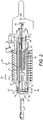
- Figure 1 illustrates an exemplary RAT system 10 which is secured to an aircraft structure 12 by a housing 14.
- the housing 14 pivotally supports a strut 16 having a turbine 18 at one end.
- the turbine 18 includes blades 20, which impart rotational drive to a generator 22 and hydraulic pump 30 for example.
- An actuator 24 is secured to the strut at a first end 26 and to the housing at a second end 28. The actuator 24 is illustrated in its deployed position.
- the actuator 24 comprises a cylinder 32 which is biased by a spring 34 in order to deploy the strut 16.
- a spring 34 in order to deploy the strut 16.
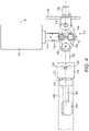
- the locking mechanism 36 comprises a locking piston or bolt 38 which is received slidably within a sleeve 40.
- the locking piston 38 is biased to the right in the sense of Figure 2 by means of a biasing spring 42 which extends between a seat 44 provided on the locking piston 38 and a seat 46 provided on the sleeve 40.
- the extensible cylinder 32 of the actuator is slidably mounted around the sleeve 40. Extension of the cylinder 32 is prevented by locking elements 48 mounted at the end of the sleeve. In the locking position, respective shoulders 50, 52 of the cylinder 32 and locking wedges 48 engage to prevent axial movement of the cylinder 32.
- a number of rollers 54 are mounted in the distal end 56 of the locking piston 38.
- the wedges 48 may displace in the direction of arrows 60 thereby disengaging the shoulders 50, 52 and allowing the cylinder 32 to extend to deploy the RAT.
- This general type of locking mechanism is known in the art and is discussed in some detail, for example in US 2013/0330121 A1 and US2013/0327885 A1 .
- the distal end 80 of the locking piston 38 is attached to a toggle release mechanism 100 illustrated only schematically in Figure 2 .
- the release mechanism 100 is movable between a locking position in which it retains the locking piston 38 in the position shown in Figure 2 and a release position in which it permits the locking piston 38 to move to the right under the force of the spring 42, move the rollers 54 of the locking piston 38 out of alignment with the locking surfaces of the locking wedges 48, thereby allowing deployment of the actuator cylinder 32.
- a toggle release mechanism in accordance with an embodiment of the disclosure will now be described with reference to Figures 3 to 5 .
- the toggle release mechanism 100 may be coupled to the locking piston 38 of the ram air turbine discussed above. However, it will be appreciated that the toggle release mechanism 100 may be used in many other applications.
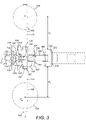
- the toggle release mechanism 100 comprises a base element 102, a toggle element 104, a link element 106, a coupling element 108 and an actuating element 110.
- the toggle element 104 is pivotally coupled at a first end 112 to the base element 102 about a first axis 114.
- the toggle element 104 in this embodiment is generally rhomboidal in shape, although other shapes of toggle element 104 are within the scope of this disclosure.
- the first end 112 of the toggle element 104 is formed with a clevis 116 which receives a clevis pin 118 about which the toggle element 104 pivots.
- the clevis pin 118 is retained in a clevis 120 formed on the base element 102 and projecting towards the toggle element 104 from a base portion 122.
- Washers 124 are arranged at respective ends of the clevis pin 118.
- a mounting element 126 projects from the base element 102 in the direction away from the toggle element 104.
- the mounting element 126 is used to locate the toggle release mechanism 100, for example in a housing, for example in the RAT actuator housing as will be described further below.
- the mounting element 126 is generally co-planar with and perpendicular to the first axis 114.
- the mounting element 126 is in this embodiment formed as a pin with a cylindrical shape, allowing the mounting element 126 to be inserted in a complementary bore in the housing and rotated about the axis of the element to allow accurate alignment of the base element 102 in the housing.
- the mounting element 126 will be a tight fit with the bore to provide accurate positioning of the base element 102.
- the base element 102 may be fastened to the housing by fasteners (not shown) which may extend through mounting bores 128 provided in the base portion 122 of the base element 102.
- a return spring mechanism 130 is provided between the base element 102 and the toggle element 104.
- the return spring mechanism 130 comprises a pair of torsion springs 132 mounted around the clevis pin 118. The springs are coiled in opposite directions.
- Each spring 132 has a first spring end 134 engaging a surface 136 at the base of the toggle clevis 112 and a second spring end 138 which is received in a respective bore 140 in the base element 102.
- first and second springs 132 are arranged symmetrically relative to the central axis C of the mechanism 100. This may be advantageous in balancing the spring loads applied to the toggle element 104.
- first and second spring ends 134, 138 are arranged to extend generally parallel to one another in vertically offset planes in the unlocked position.
- first spring ends 134 are above the second spring ends 138, although the positions may, for example, be reversed. It will also be noted that the respective first spring ends 134 are arranged closer together than the second spring ends 138.
- the toggle element 104 receives the actuating element 110.
- the actuating element 110 is a rod 142 which has a central portion 144 received in a through bore 145 of the toggle element 104 and first and second end portions 146, 148 projecting from respective sides of the toggle element 104.
- the first and second end portions 146, 148 are received within respective slots 150 of plungers 152 of respective linear solenoid actuators 154, illustrated schematically in Figures 3 and 4 .
- Two actuators 154 are provided to provide for redundancy and failsafe operation, movement of one actuator 154 being sufficient to operate the toggle mechanism 100.
- the slot 150 has a width W which is greater than the diameter D of the actuator rod 142 so as to allow some movement of the rod 142 within the slot in the axial direction.
- the solenoid actuator 154 produces an actuating movement transverse to the axis C as illustrated in Figure 4 by arrow B.
- the actuator rod 142 is mounted to the toggle element 104 by means of a mounting flange 156 formed at the boundary between the central portion 144 and the first end portion 146 of the actuating rod 142.
- the mounting flange 156 is, in this embodiment, a generally triangular plate-like element, although other shapes may be employed.
- the mounting flange 156 is integrally formed with the actuating rod 142.
- the mounting flange 156 is provided with a first opening 158 therethrough to receive a first fastener 160, for example a threaded fastener 160 as shown.
- the surface 162 of the toggle element 104 facing the mounting flange 156 is provided with a first bore 164, e.g. a threaded bore, for receiving the first fastener 160. When received in the first bore 164 and tightened, the first fastener 160 will securely mount the actuator rod 142 to the toggle element 104.
- the point of action of the actuator force on either side of the toggle element 104 is not symmetrical as the actuator force on the second end 148 actuator rod 142 is also effectively applied through the mounting flange 156.
- the actuator rod 142 may also deflect due to the gap G before the actuating force is transmitted to the toggle element 104.
- a further mounting element 166 is provided.
- the mounting element 166 is slidably received over the second end portion 148 of the actuating rod 142.
- the mounting element 166 has a bore 168 for receiving the actuating rod 142 and a second hole 170 for receiving a second fastener 172, for example a threaded fastener 172.
- the surface 174 of the toggle element 104 facing the mounting element 166 is provided with a second bore 176, for example a threaded bore 176 to receive the second fastener 172.
- the first and second bores 164, 176 of the toggle element 104 are aligned along a common axis X.
- the common axis X is parallel to and directly above the axis Y of the actuator rod 142.
- the bores 164, 176 are arranged at an apex 180 of the toggle element 104 so as to minimise interference with other elements of the mechanism 100.
- the mounting element 166 is, in this embodiment, in the form of a generally triangular plate having a shape and a thickness generally similar to that of the mounting flange 156 of the actuator rod 142.
- the second end portion 148 of the actuating rod 142 is received with a close fit within the bore 168 of the mounting element 166 such that there is a smaller clearance (if any clearance at all) formed between the actuating rod 142 and the mounting element 166 than between the actuating rod 142 and the toggle element bore 145.
- This arrangement may provide a number of benefits compared to arrangements with just a mounting flange 156.
- the second end 148 of the actuator arm 142 is now located much more accurately relative to the toggle element 104, meaning that the engagement of the actuator slot 150 with the actuator end portions 146, 148 can be more accurately set, thereby reducing or eliminating differences in actuator stroke length needed to trigger the mechanism 100.
- the actuator force acting on the second end portion of the actuator rod is transmitted into the toggle element 104 from the actuators 154 through the mounting plate 166 rather than mounting flange 156.
- actuating forces are applied in a more symmetrical manner on opposed sides of the toggle element 104.
- Figure 3 which illustrates the distances d1 and d2 between the outwardly facing surfaces of the mounting flange 156 and mounting element 166, and the point of application of force from the respective actuators 154.
- the distances d1 and d2 are the same, meaning that the forces transmitted into the toggle element 104 will be the same (assuming the individual actuator forces are the same).
- the use of the mounting element 166 therefore leads to more reliable and consistent operation of the mechanism. There is potentially also no need to oversize the actuators 154 to account for unequal operating forces on the actuator rod, allowing a potentially more compact installation.
- the link element 106 is pivotally connected to a second end 180 of the toggle element 104 about a second pivot axis 182 which is parallel to the first axis 114.
- the second end 180 of the toggle element 104 is also formed with a clevis 186, receiving a clevis pin 188 which extends through a first end 190 of the link element 106 and forms the second pivot axis 182.
- a second end 192 of the link element 106 is pivotally connected to the coupling element 108 about a third pivot axis 194 which is parallel to the first and second axes 114, 182.
- the coupling element 108 is formed with a clevis 196 which receives a clevis pin 198 which extends through the second end of the link element 106 and forms the third pivot axis 194.
- the coupling element 108 is formed with an end surface 200 which abuts the end surface 202 of the locking piston 38.
- the coupling element 108 further comprises a stem 204 which is received within a bore 206 formed in the adjacent end of the locking piston 38.
- Three or more fins 208 projecting from the stem 204 assist in locating the coupling element 108 within the bore 206.
- the fins 208 are typically equispaced around the circumference of the stem 204.
- the stem 204 may be easily removable from the bore 206. This may facilitate location of the coupling element 108.
- the coupling element 108 is constrained to move in an axial direction along axis A which passes through the first pivot axis 114 by virtue of its mounting to the locking piston 38, since the locking piston 38 is slidably mounted (by suitable means not shown) for movement along the axis C.
- the base element 102 is mounted to a support surface in the actuating mechanism or other mechanism to be released. As discussed above, this may be effected through the mounting element 126. In the context of the RAT actuator disclosed in Figures 1 and 2 , the base element may be suitably mounted in a head region 200 of the actuator.
- the coupling element 108 is then coupled to the locking element of the mechanism, be released.
- the coupling element 108 is coupled to the end of the locking piston 38 by virtue of the stem 202 of the coupling element 108 being received within the bore 204 of the locking piston 38, the opposed surfaces 200, 202 of the coupling element 108 and the locking piston 38 abutting.
- the biasing spring 42 of the RAT locking mechanism exerts a force F in the axial direction A.
- the toggle release mechanism 100 will hold the locking piston 38 when it is in the locking position shown in the Figures.
- the solenoid actuators 154 When it is desired to unlock the RAT actuator, the solenoid actuators 154 are operated, pulling the actuating rod 142 upwardly in the sense of the Figures against the biasing force of the torsion springs132. This will rotate the toggle element 104 clockwise about the first axis 114.
- the provision of the mounting element 166 equalises the forces acting on the toggle element 104, leading to a more consistent and repeatable operation.
- the biasing force of the actuator biasing spring 42 will maintain the toggle element 104 in this position, and the solenoid actuators 154 may be de-energised.
- a spring provided within the solenoid actuator 154 may move the solenoid back it into its initial position.
Landscapes
- Engineering & Computer Science (AREA)
- General Engineering & Computer Science (AREA)
- Aviation & Aerospace Engineering (AREA)
- Mechanical Engineering (AREA)
- Transmission Devices (AREA)
- Actuator (AREA)
Claims (15)
- Kniehebelfreigabemechanismus (100), umfassend:ein Basiselement (102);ein Kniehebelelement (104), das an einem ersten Ende (112) an dem Basiselement (102) drehbar um eine erste Achse (114) zur Drehung zwischen einer ersten Verriegelungsposition und einer zweiten Freigabeposition montiert ist; undeine Betätigungsstange (142), die einen zentralen Abschnitt (144), der sich durch das Kniehebelelement (104) erstreckt, und einen ersten und einen zweiten Endabschnitt (146, 148), die an gegenüberliegenden Seiten davon hervorragen, aufweist;zwei lineare Magnetaktoren (154), die an gegenüberliegenden Seiten des Freigabemechanismus (100) angeordnet sind und jeweils einen Kolben (152) mit einem Schlitz (150) darin aufweisen;wobei der erste und der zweite Endabschnitt (146, 148) jeweils in den Schlitz (150) des Kolbens (152) eines jeweiligen der linearen Magnetaktoren (154) eingreifen;wobei die Betätigungsstange (142) einen Montageflansch (156) umfasst, der die Betätigungsstange (142) an dem Kniehebelelement (104) montiert, wobei der Montageflansch (156) mit der Betätigungsstange (142) einstückig ausgebildet ist und aus der Betätigungsstange (142) an einer Grenze zwischen dem zentralen Abschnitt (144) und einem ersten Endabschnitt (146) hervorragt, wobei der Montageflansch (156) ein erstes Loch (158) darin zum Aufnehmen eines ersten Befestigungselements (160) aufweist;wobei eine Fläche (162) des Kniehebelelements (104), die dem Montageflansch (156) zugewandt ist, eine darin ausgebildete Bohrung (164) zum Aufnehmen des ersten Befestigungselements (160) aufweist; und ferner umfassend:ein Montageelement (166), das an dem zweiten Ende (148) der Betätigungsstange (142) gleitend aufgenommen wird, wobei das Montageelement (166) eine Bohrung (168) zum Aufnehmen des zweiten Endes (148) der Betätigungsstange (142) und ein zweites Loch (170) zum Aufnehmen eines zweiten Befestigungselements (176) aufweist; undeine Fläche (174) des Kniehebelelements (104), die dem Montageelement (166) zugewandt ist und eine zweite darin ausgebildete Bohrung (176) zum Aufnehmen des zweiten Befestigungselements (172) aufweist.
- Kniehebelfreigabemechanismus nach Anspruch 1, wobei das Montageelement (166) ein plattenartiges Element ist und optional im Allgemeinen dreieckig ist.
- Kniehebelfreigabemechanismus nach Anspruch 2, wobei die Montageelementplatte (166) eine Dicke aufweist, die im Wesentlichen gleich wie die Dicke des Montageflansches (156) ist.
- Kniehebelfreigabemechanismus nach Anspruch 2 oder 3, wobei das Montageelement (166) eine Form aufweist, die im Allgemeinen ähnlich wie die des Montageflansches (156) ist.
- Kniehebelfreigabemechanismus nach einem der vorangehenden Ansprüche, wobei das erste und das zweite Loch (158, 170) in dem Montageflansch (156) und dem Montageelement (166) und die erste und die zweite Bohrung (164, 176) in dem Kniehebelelement (104) entlang einer gemeinsamen Achse (X) ausgerichtet sind, wobei die gemeinsame Achse (X) optional parallel zu der ersten Achse (114) ist und mit dieser vertikal ausgerichtet.
- Kniehebelfreigabemechanismus nach einem der vorangehenden Ansprüche, wobei das Kniehebelelement (104) im Allgemeinen eine rhombische Form aufweist und die erste und die zweite Bohrung (164, 176) an einem Scheitelpunkt des Rhombus angeordnet sind.
- Kniehebelfreigabemechanismus nach einem der vorangehenden Ansprüche, wobei das Montageelement (166) dicht an das zweite Ende (148) der Betätigungsstange (142) anschließt.
- Kniehebelfreigabemechanismus nach einem der vorangehenden Ansprüche, ferner umfassend einen Rückstellfedermechanismus (130), der zwischen dem Basiselement (102) und dem Kniehebelelement (104) zum Drehen des Kniehebelelements (104) in eine Richtung in Richtung der Verriegelungsposition bereitgestellt ist.
- Kniehebelfreigabemechanismus nach Anspruch 8, wobei der Rückstellfedermechanismus eine erste und eine zweite Feder (132) umfasst, die zwischen dem Basiselement (102) und dem Kniehebelelement (104) montiert sind.
- Kniehebelfreigabemechanismus nach Anspruch 9, wobei die erste und die zweite Feder (132) Torsionsfedern sind, die zwischen dem Kniehebelelement (104) und dem Basiselement (102) montiert sind, wobei die erste und die zweite Torsionsfeder optional in entgegengesetzte Richtungen gewickelt sind.
- Kniehebelfreigabemechanismus nach Anspruch 9 oder 10, wobei die erste und die zweite Feder (132) symmetrisch um die zentrale Achse (C) des Kniehebelelements (104) angeordnet sind.
- Kniehebelfreigabemechanismus nach Anspruch 10 oder 11, wobei jede Torsionsfeder (132) einen ersten Schenkel (134), der sich an einem Ende davon erstreckt, um eine Aufnahmefläche (136) an dem Kniehebelelement (104) in Eingriff zu nehmen, und einen zweiten Schenkel (138), der sich an dem anderen Ende davonerstreckt, um das Basiselement (102) in Eingriff zu nehmen, umfasst, wobei optional die jeweiligen ersten Schenkel (134) enger zusammen angeordnet sind als die jeweiligen zweiten Schenkel (138).
- Kniehebelfreigabemechanismus nach Anspruch 12, wobei sich der erste und der zweite Schenkel (134, 138) in der verriegelten Position des Mechanismus (100) parallel zueinander in vertikal versetzten Ebenen erstrecken.
- Kniehebelfreigabemechanismus nach einem der vorangehenden Ansprüche, ferner umfassend ein Verbindungselement (106), das an einem ersten Ende (190) an einem zweiten Ende (180) des Kniehebelelements (104) um eine zweite Achse (182) parallel zu der ersten Achse (114) montiert ist.
- Stauluftturbinenbetätigungsmechanismus (36), umfassend einen federvorgespannten Verriegelungskolben (38), der zwischen einer ersten Position, in der die Stauluftturbine in einer eingezogenen Position gehalten wird, und einer zweiten Position, die die Stauluftturbine freigibt, beweglich ist, wobei der Stauluftturbinenbetätigungsmechanismus ferner einen Kniehebelfreigabemechanismus (100) nach einem der vorangehenden Ansprüche umfasst, wobei der Verriegelungskolben (38) an das Verbindungselement des Kniehebelfreigabemechanismus gekoppelt ist, um eine Kraft in einer Richtung in Richtung des Basiselements des Kniehebelfreigabemechanismus (100) darauf auszuüben, wobei optional der Kniehebelfreigabemechanismus ferner ein Kopplungselement (108) umfasst, das an einem zweiten Ende (192) des Verbindungselements (106) um eine dritte Achse (194) parallel zu der ersten und der zweiten Achse (114, 182) montiert ist, und wobei der Verriegelungskolben (38) an das Kopplungselement (108) anstößt, wobei das Kopplungselement (108) optional einen Schaft (202) umfasst, der in einer Bohrung (204) des Verriegelungskolbens (38) aufgenommen wird.
Priority Applications (3)
| Application Number | Priority Date | Filing Date | Title |
|---|---|---|---|
| EP17461504.7A EP3348486B1 (de) | 2017-01-14 | 2017-01-14 | Auslösemechanismus |
| PL17461504T PL3348486T3 (pl) | 2017-01-14 | 2017-01-14 | Mechanizm zwalniający |
| US15/869,132 US10370115B2 (en) | 2017-01-14 | 2018-01-12 | Release mechanism |
Applications Claiming Priority (1)
| Application Number | Priority Date | Filing Date | Title |
|---|---|---|---|
| EP17461504.7A EP3348486B1 (de) | 2017-01-14 | 2017-01-14 | Auslösemechanismus |
Publications (2)
| Publication Number | Publication Date |
|---|---|
| EP3348486A1 EP3348486A1 (de) | 2018-07-18 |
| EP3348486B1 true EP3348486B1 (de) | 2022-04-06 |
Family
ID=57821905
Family Applications (1)
| Application Number | Title | Priority Date | Filing Date |
|---|---|---|---|
| EP17461504.7A Active EP3348486B1 (de) | 2017-01-14 | 2017-01-14 | Auslösemechanismus |
Country Status (3)
| Country | Link |
|---|---|
| US (1) | US10370115B2 (de) |
| EP (1) | EP3348486B1 (de) |
| PL (1) | PL3348486T3 (de) |
Families Citing this family (2)
| Publication number | Priority date | Publication date | Assignee | Title |
|---|---|---|---|---|
| US9821919B2 (en) | 2016-03-11 | 2017-11-21 | Hamilton Sundstrand Corporation | Ejection jack having a toggle assembly |
| EP3284678B1 (de) * | 2016-08-19 | 2019-04-24 | Hamilton Sundstrand Corporation | Auslösemechanismus |
Family Cites Families (20)
| Publication number | Priority date | Publication date | Assignee | Title |
|---|---|---|---|---|
| GB650016A (en) * | 1948-09-20 | 1951-02-07 | Vauxhall Motors Ltd | Improvements in and relating to windscreen wiper mechanisms |
| US2694935A (en) * | 1952-04-28 | 1954-11-23 | Roehri Carl | Reciprocating and locking apparatus |
| FR83445E (fr) * | 1963-01-22 | 1964-08-07 | Salomon & Fils F | Dispositif perfectionné de fixation arrière de sécurité pour skis |
| US3440933A (en) * | 1966-12-02 | 1969-04-29 | Hammond Machinery Builders Inc | Adjustable stroke control device |
| US4676458A (en) * | 1984-12-24 | 1987-06-30 | Sundstrand Corporation | Deployment mechanism for a ram air turbine |
| FR2651527B1 (fr) * | 1989-09-05 | 1995-08-04 | Aerospatiale | Systeme pour le verrouillage d'au moins deux elements relativement deplacables l'un par rapport a l'autre. |
| EP1383978B1 (de) * | 2001-04-30 | 2011-03-09 | Southco, Inc. | Verriegelungsanordnung |
| WO2009146148A2 (en) * | 2008-04-04 | 2009-12-03 | Tactair Fluid Controls, Inc. | Locking mechanism with bi-modal actuator |
| WO2013172804A1 (en) * | 2012-05-16 | 2013-11-21 | Tusaş-Türk Havacilik Ve Uzay Sanayii A.Ş. | A door latch mechanism |
| US9511875B2 (en) | 2012-06-06 | 2016-12-06 | Hamilton Sundstrand Corporation | Electromechanical actuator damping arrangement for ram air turbine |
| US9193472B2 (en) | 2012-06-06 | 2015-11-24 | Hamilton Sundstrand Corporation | Electromechanical actuator lubrication system for ram air turbine |
| US9365295B2 (en) | 2012-06-06 | 2016-06-14 | Hamilton Sundstrand Corporation | Electromechanical actuator and latch assembly for ram air turbine |
| EP3023677B1 (de) * | 2014-11-20 | 2018-03-07 | Hamilton Sundstrand Corporation | Rückschlagventile |
| US10106275B2 (en) | 2015-04-02 | 2018-10-23 | Hamilton Sundstrand Corporation | Ram air turbine stowing system |
| US9976636B2 (en) * | 2015-04-22 | 2018-05-22 | Hamilton Sundstrand Corporation | Locking mechanisms for ram air turbines |
| PL3196127T3 (pl) * | 2016-01-20 | 2019-04-30 | Hamilton Sundstrand Corp | Mechanizm blokujący i odblokowujący |
| US9821919B2 (en) * | 2016-03-11 | 2017-11-21 | Hamilton Sundstrand Corporation | Ejection jack having a toggle assembly |
| US10829240B2 (en) * | 2016-03-11 | 2020-11-10 | Hamilton Sundstrand Corporation | Cross rod for toggle mechanism of ram air turbine actuator |
| US10385784B2 (en) * | 2016-03-11 | 2019-08-20 | Hamilton Sundstrand Corporation | Clevis link for toggle mechanism of ram air turbine actuator |
| EP3284678B1 (de) * | 2016-08-19 | 2019-04-24 | Hamilton Sundstrand Corporation | Auslösemechanismus |
-
2017
- 2017-01-14 PL PL17461504T patent/PL3348486T3/pl unknown
- 2017-01-14 EP EP17461504.7A patent/EP3348486B1/de active Active
-
2018
- 2018-01-12 US US15/869,132 patent/US10370115B2/en active Active
Non-Patent Citations (1)
| Title |
|---|
| None * |
Also Published As
| Publication number | Publication date |
|---|---|
| PL3348486T3 (pl) | 2022-07-04 |
| US10370115B2 (en) | 2019-08-06 |
| US20180201389A1 (en) | 2018-07-19 |
| EP3348486A1 (de) | 2018-07-18 |
Similar Documents
| Publication | Publication Date | Title |
|---|---|---|
| US20200023991A1 (en) | Locking and unlocking mechanism | |
| US10317929B2 (en) | Locking and unlocking mechanism | |
| US10533647B2 (en) | Locking and unlocking mechanism | |
| US10370115B2 (en) | Release mechanism | |
| US10247285B2 (en) | Locking and unlocking mechanism for ram air turbine | |
| US10717544B2 (en) | Release mechanism | |
| EP3216701B1 (de) | Verriegelungsmechanismus | |
| US11014685B2 (en) | Release mechanism | |
| US10310543B2 (en) | Actuator release mechanism | |
| US10753440B2 (en) | Actuator release mechanism | |
| EP3495669B1 (de) | Verriegelungsmechanismus | |
| EP3184437B1 (de) | Entriegelungsmechanismus für eine stauluftturbine aktuator | |
| EP3279093B1 (de) | Auslösemechanismus | |
| EP3741681B1 (de) | Verriegelungs- und entriegelungsmechanismus |
Legal Events
| Date | Code | Title | Description |
|---|---|---|---|
| PUAI | Public reference made under article 153(3) epc to a published international application that has entered the european phase |
Free format text: ORIGINAL CODE: 0009012 |
|
| STAA | Information on the status of an ep patent application or granted ep patent |
Free format text: STATUS: THE APPLICATION HAS BEEN PUBLISHED |
|
| AK | Designated contracting states |
Kind code of ref document: A1 Designated state(s): AL AT BE BG CH CY CZ DE DK EE ES FI FR GB GR HR HU IE IS IT LI LT LU LV MC MK MT NL NO PL PT RO RS SE SI SK SM TR |
|
| AX | Request for extension of the european patent |
Extension state: BA ME |
|
| STAA | Information on the status of an ep patent application or granted ep patent |
Free format text: STATUS: REQUEST FOR EXAMINATION WAS MADE |
|
| 17P | Request for examination filed |
Effective date: 20190117 |
|
| RBV | Designated contracting states (corrected) |
Designated state(s): AL AT BE BG CH CY CZ DE DK EE ES FI FR GB GR HR HU IE IS IT LI LT LU LV MC MK MT NL NO PL PT RO RS SE SI SK SM TR |
|
| STAA | Information on the status of an ep patent application or granted ep patent |
Free format text: STATUS: EXAMINATION IS IN PROGRESS |
|
| 17Q | First examination report despatched |
Effective date: 20190905 |
|
| GRAP | Despatch of communication of intention to grant a patent |
Free format text: ORIGINAL CODE: EPIDOSNIGR1 |
|
| STAA | Information on the status of an ep patent application or granted ep patent |
Free format text: STATUS: GRANT OF PATENT IS INTENDED |
|
| INTG | Intention to grant announced |
Effective date: 20211020 |
|
| GRAS | Grant fee paid |
Free format text: ORIGINAL CODE: EPIDOSNIGR3 |
|
| GRAA | (expected) grant |
Free format text: ORIGINAL CODE: 0009210 |
|
| STAA | Information on the status of an ep patent application or granted ep patent |
Free format text: STATUS: THE PATENT HAS BEEN GRANTED |
|
| AK | Designated contracting states |
Kind code of ref document: B1 Designated state(s): AL AT BE BG CH CY CZ DE DK EE ES FI FR GB GR HR HU IE IS IT LI LT LU LV MC MK MT NL NO PL PT RO RS SE SI SK SM TR |
|
| REG | Reference to a national code |
Ref country code: GB Ref legal event code: FG4D |
|
| REG | Reference to a national code |
Ref country code: CH Ref legal event code: EP |
|
| REG | Reference to a national code |
Ref country code: AT Ref legal event code: REF Ref document number: 1481130 Country of ref document: AT Kind code of ref document: T Effective date: 20220415 |
|
| REG | Reference to a national code |
Ref country code: DE Ref legal event code: R096 Ref document number: 602017055490 Country of ref document: DE |
|
| REG | Reference to a national code |
Ref country code: IE Ref legal event code: FG4D |
|
| REG | Reference to a national code |
Ref country code: LT Ref legal event code: MG9D |
|
| REG | Reference to a national code |
Ref country code: NL Ref legal event code: MP Effective date: 20220406 |
|
| REG | Reference to a national code |
Ref country code: AT Ref legal event code: MK05 Ref document number: 1481130 Country of ref document: AT Kind code of ref document: T Effective date: 20220406 |
|
| PG25 | Lapsed in a contracting state [announced via postgrant information from national office to epo] |
Ref country code: NL Free format text: LAPSE BECAUSE OF FAILURE TO SUBMIT A TRANSLATION OF THE DESCRIPTION OR TO PAY THE FEE WITHIN THE PRESCRIBED TIME-LIMIT Effective date: 20220406 |
|
| PG25 | Lapsed in a contracting state [announced via postgrant information from national office to epo] |
Ref country code: SE Free format text: LAPSE BECAUSE OF FAILURE TO SUBMIT A TRANSLATION OF THE DESCRIPTION OR TO PAY THE FEE WITHIN THE PRESCRIBED TIME-LIMIT Effective date: 20220406 Ref country code: PT Free format text: LAPSE BECAUSE OF FAILURE TO SUBMIT A TRANSLATION OF THE DESCRIPTION OR TO PAY THE FEE WITHIN THE PRESCRIBED TIME-LIMIT Effective date: 20220808 Ref country code: NO Free format text: LAPSE BECAUSE OF FAILURE TO SUBMIT A TRANSLATION OF THE DESCRIPTION OR TO PAY THE FEE WITHIN THE PRESCRIBED TIME-LIMIT Effective date: 20220706 Ref country code: LT Free format text: LAPSE BECAUSE OF FAILURE TO SUBMIT A TRANSLATION OF THE DESCRIPTION OR TO PAY THE FEE WITHIN THE PRESCRIBED TIME-LIMIT Effective date: 20220406 Ref country code: HR Free format text: LAPSE BECAUSE OF FAILURE TO SUBMIT A TRANSLATION OF THE DESCRIPTION OR TO PAY THE FEE WITHIN THE PRESCRIBED TIME-LIMIT Effective date: 20220406 Ref country code: GR Free format text: LAPSE BECAUSE OF FAILURE TO SUBMIT A TRANSLATION OF THE DESCRIPTION OR TO PAY THE FEE WITHIN THE PRESCRIBED TIME-LIMIT Effective date: 20220707 Ref country code: FI Free format text: LAPSE BECAUSE OF FAILURE TO SUBMIT A TRANSLATION OF THE DESCRIPTION OR TO PAY THE FEE WITHIN THE PRESCRIBED TIME-LIMIT Effective date: 20220406 Ref country code: ES Free format text: LAPSE BECAUSE OF FAILURE TO SUBMIT A TRANSLATION OF THE DESCRIPTION OR TO PAY THE FEE WITHIN THE PRESCRIBED TIME-LIMIT Effective date: 20220406 Ref country code: BG Free format text: LAPSE BECAUSE OF FAILURE TO SUBMIT A TRANSLATION OF THE DESCRIPTION OR TO PAY THE FEE WITHIN THE PRESCRIBED TIME-LIMIT Effective date: 20220706 Ref country code: AT Free format text: LAPSE BECAUSE OF FAILURE TO SUBMIT A TRANSLATION OF THE DESCRIPTION OR TO PAY THE FEE WITHIN THE PRESCRIBED TIME-LIMIT Effective date: 20220406 |
|
| PG25 | Lapsed in a contracting state [announced via postgrant information from national office to epo] |
Ref country code: RS Free format text: LAPSE BECAUSE OF FAILURE TO SUBMIT A TRANSLATION OF THE DESCRIPTION OR TO PAY THE FEE WITHIN THE PRESCRIBED TIME-LIMIT Effective date: 20220406 Ref country code: LV Free format text: LAPSE BECAUSE OF FAILURE TO SUBMIT A TRANSLATION OF THE DESCRIPTION OR TO PAY THE FEE WITHIN THE PRESCRIBED TIME-LIMIT Effective date: 20220406 Ref country code: IS Free format text: LAPSE BECAUSE OF FAILURE TO SUBMIT A TRANSLATION OF THE DESCRIPTION OR TO PAY THE FEE WITHIN THE PRESCRIBED TIME-LIMIT Effective date: 20220806 |
|
| REG | Reference to a national code |
Ref country code: DE Ref legal event code: R097 Ref document number: 602017055490 Country of ref document: DE |
|
| PG25 | Lapsed in a contracting state [announced via postgrant information from national office to epo] |
Ref country code: SM Free format text: LAPSE BECAUSE OF FAILURE TO SUBMIT A TRANSLATION OF THE DESCRIPTION OR TO PAY THE FEE WITHIN THE PRESCRIBED TIME-LIMIT Effective date: 20220406 Ref country code: SK Free format text: LAPSE BECAUSE OF FAILURE TO SUBMIT A TRANSLATION OF THE DESCRIPTION OR TO PAY THE FEE WITHIN THE PRESCRIBED TIME-LIMIT Effective date: 20220406 Ref country code: RO Free format text: LAPSE BECAUSE OF FAILURE TO SUBMIT A TRANSLATION OF THE DESCRIPTION OR TO PAY THE FEE WITHIN THE PRESCRIBED TIME-LIMIT Effective date: 20220406 Ref country code: EE Free format text: LAPSE BECAUSE OF FAILURE TO SUBMIT A TRANSLATION OF THE DESCRIPTION OR TO PAY THE FEE WITHIN THE PRESCRIBED TIME-LIMIT Effective date: 20220406 Ref country code: DK Free format text: LAPSE BECAUSE OF FAILURE TO SUBMIT A TRANSLATION OF THE DESCRIPTION OR TO PAY THE FEE WITHIN THE PRESCRIBED TIME-LIMIT Effective date: 20220406 Ref country code: CZ Free format text: LAPSE BECAUSE OF FAILURE TO SUBMIT A TRANSLATION OF THE DESCRIPTION OR TO PAY THE FEE WITHIN THE PRESCRIBED TIME-LIMIT Effective date: 20220406 |
|
| PLBE | No opposition filed within time limit |
Free format text: ORIGINAL CODE: 0009261 |
|
| STAA | Information on the status of an ep patent application or granted ep patent |
Free format text: STATUS: NO OPPOSITION FILED WITHIN TIME LIMIT |
|
| 26N | No opposition filed |
Effective date: 20230110 |
|
| PG25 | Lapsed in a contracting state [announced via postgrant information from national office to epo] |
Ref country code: AL Free format text: LAPSE BECAUSE OF FAILURE TO SUBMIT A TRANSLATION OF THE DESCRIPTION OR TO PAY THE FEE WITHIN THE PRESCRIBED TIME-LIMIT Effective date: 20220406 |
|
| PG25 | Lapsed in a contracting state [announced via postgrant information from national office to epo] |
Ref country code: SI Free format text: LAPSE BECAUSE OF FAILURE TO SUBMIT A TRANSLATION OF THE DESCRIPTION OR TO PAY THE FEE WITHIN THE PRESCRIBED TIME-LIMIT Effective date: 20220406 |
|
| P01 | Opt-out of the competence of the unified patent court (upc) registered |
Effective date: 20230522 |
|
| REG | Reference to a national code |
Ref country code: DE Ref legal event code: R119 Ref document number: 602017055490 Country of ref document: DE |
|
| REG | Reference to a national code |
Ref country code: CH Ref legal event code: PL |
|
| GBPC | Gb: european patent ceased through non-payment of renewal fee |
Effective date: 20230114 |
|
| PG25 | Lapsed in a contracting state [announced via postgrant information from national office to epo] |
Ref country code: LU Free format text: LAPSE BECAUSE OF NON-PAYMENT OF DUE FEES Effective date: 20230114 |
|
| REG | Reference to a national code |
Ref country code: BE Ref legal event code: MM Effective date: 20230131 |
|
| PG25 | Lapsed in a contracting state [announced via postgrant information from national office to epo] |
Ref country code: LI Free format text: LAPSE BECAUSE OF NON-PAYMENT OF DUE FEES Effective date: 20230131 Ref country code: GB Free format text: LAPSE BECAUSE OF NON-PAYMENT OF DUE FEES Effective date: 20230114 Ref country code: DE Free format text: LAPSE BECAUSE OF NON-PAYMENT OF DUE FEES Effective date: 20230801 Ref country code: CH Free format text: LAPSE BECAUSE OF NON-PAYMENT OF DUE FEES Effective date: 20230131 |
|
| PG25 | Lapsed in a contracting state [announced via postgrant information from national office to epo] |
Ref country code: BE Free format text: LAPSE BECAUSE OF NON-PAYMENT OF DUE FEES Effective date: 20230131 |
|
| PG25 | Lapsed in a contracting state [announced via postgrant information from national office to epo] |
Ref country code: IT Free format text: LAPSE BECAUSE OF FAILURE TO SUBMIT A TRANSLATION OF THE DESCRIPTION OR TO PAY THE FEE WITHIN THE PRESCRIBED TIME-LIMIT Effective date: 20220406 Ref country code: IE Free format text: LAPSE BECAUSE OF NON-PAYMENT OF DUE FEES Effective date: 20230114 |
|
| PG25 | Lapsed in a contracting state [announced via postgrant information from national office to epo] |
Ref country code: MC Free format text: LAPSE BECAUSE OF FAILURE TO SUBMIT A TRANSLATION OF THE DESCRIPTION OR TO PAY THE FEE WITHIN THE PRESCRIBED TIME-LIMIT Effective date: 20220406 |
|
| PG25 | Lapsed in a contracting state [announced via postgrant information from national office to epo] |
Ref country code: MC Free format text: LAPSE BECAUSE OF FAILURE TO SUBMIT A TRANSLATION OF THE DESCRIPTION OR TO PAY THE FEE WITHIN THE PRESCRIBED TIME-LIMIT Effective date: 20220406 |
|
| PG25 | Lapsed in a contracting state [announced via postgrant information from national office to epo] |
Ref country code: BG Free format text: LAPSE BECAUSE OF FAILURE TO SUBMIT A TRANSLATION OF THE DESCRIPTION OR TO PAY THE FEE WITHIN THE PRESCRIBED TIME-LIMIT Effective date: 20220406 |
|
| PG25 | Lapsed in a contracting state [announced via postgrant information from national office to epo] |
Ref country code: BG Free format text: LAPSE BECAUSE OF FAILURE TO SUBMIT A TRANSLATION OF THE DESCRIPTION OR TO PAY THE FEE WITHIN THE PRESCRIBED TIME-LIMIT Effective date: 20220406 |
|
| PGFP | Annual fee paid to national office [announced via postgrant information from national office to epo] |
Ref country code: PL Payment date: 20241223 Year of fee payment: 9 |
|
| PGFP | Annual fee paid to national office [announced via postgrant information from national office to epo] |
Ref country code: FR Payment date: 20241220 Year of fee payment: 9 |
|
| PG25 | Lapsed in a contracting state [announced via postgrant information from national office to epo] |
Ref country code: CY Free format text: LAPSE BECAUSE OF FAILURE TO SUBMIT A TRANSLATION OF THE DESCRIPTION OR TO PAY THE FEE WITHIN THE PRESCRIBED TIME-LIMIT; INVALID AB INITIO Effective date: 20170114 |
|
| PG25 | Lapsed in a contracting state [announced via postgrant information from national office to epo] |
Ref country code: HU Free format text: LAPSE BECAUSE OF FAILURE TO SUBMIT A TRANSLATION OF THE DESCRIPTION OR TO PAY THE FEE WITHIN THE PRESCRIBED TIME-LIMIT; INVALID AB INITIO Effective date: 20170114 |
|
| PG25 | Lapsed in a contracting state [announced via postgrant information from national office to epo] |
Ref country code: TR Free format text: LAPSE BECAUSE OF FAILURE TO SUBMIT A TRANSLATION OF THE DESCRIPTION OR TO PAY THE FEE WITHIN THE PRESCRIBED TIME-LIMIT Effective date: 20220406 |