EP3348364A1 - A handle for a shaver enabling rotational movement of a cartridge - Google Patents
A handle for a shaver enabling rotational movement of a cartridge Download PDFInfo
- Publication number
- EP3348364A1 EP3348364A1 EP17151799.8A EP17151799A EP3348364A1 EP 3348364 A1 EP3348364 A1 EP 3348364A1 EP 17151799 A EP17151799 A EP 17151799A EP 3348364 A1 EP3348364 A1 EP 3348364A1
- Authority
- EP
- European Patent Office
- Prior art keywords
- handle
- connector
- cartridge
- elastic tongue
- axis
- Prior art date
- Legal status (The legal status is an assumption and is not a legal conclusion. Google has not performed a legal analysis and makes no representation as to the accuracy of the status listed.)
- Granted
Links
- 230000033001 locomotion Effects 0.000 title description 13
- 230000007935 neutral effect Effects 0.000 claims abstract description 7
- 230000007423 decrease Effects 0.000 claims description 3
- 230000000295 complement effect Effects 0.000 description 5
- 239000000463 material Substances 0.000 description 3
- 230000014759 maintenance of location Effects 0.000 description 2
- 239000002184 metal Substances 0.000 description 2
- 230000000717 retained effect Effects 0.000 description 2
- 230000035945 sensitivity Effects 0.000 description 2
- 238000004026 adhesive bonding Methods 0.000 description 1
- 230000003247 decreasing effect Effects 0.000 description 1
- 238000009877 rendering Methods 0.000 description 1
- 210000005182 tip of the tongue Anatomy 0.000 description 1
- 238000003466 welding Methods 0.000 description 1
Images


Classifications
-
- B—PERFORMING OPERATIONS; TRANSPORTING
- B26—HAND CUTTING TOOLS; CUTTING; SEVERING
- B26B—HAND-HELD CUTTING TOOLS NOT OTHERWISE PROVIDED FOR
- B26B21/00—Razors of the open or knife type; Safety razors or other shaving implements of the planing type; Hair-trimming devices involving a razor-blade; Equipment therefor
- B26B21/40—Details or accessories
- B26B21/52—Handles, e.g. tiltable, flexible
- B26B21/521—Connection details, e.g. connection to razor heads
-
- B—PERFORMING OPERATIONS; TRANSPORTING
- B26—HAND CUTTING TOOLS; CUTTING; SEVERING
- B26B—HAND-HELD CUTTING TOOLS NOT OTHERWISE PROVIDED FOR
- B26B21/00—Razors of the open or knife type; Safety razors or other shaving implements of the planing type; Hair-trimming devices involving a razor-blade; Equipment therefor
- B26B21/08—Razors of the open or knife type; Safety razors or other shaving implements of the planing type; Hair-trimming devices involving a razor-blade; Equipment therefor involving changeable blades
- B26B21/14—Safety razors with one or more blades arranged transversely to the handle
- B26B21/22—Safety razors with one or more blades arranged transversely to the handle involving several blades to be used simultaneously
- B26B21/222—Safety razors with one or more blades arranged transversely to the handle involving several blades to be used simultaneously with the blades moulded into, or attached to, a changeable unit
- B26B21/225—Safety razors with one or more blades arranged transversely to the handle involving several blades to be used simultaneously with the blades moulded into, or attached to, a changeable unit the changeable unit being resiliently mounted on the handle
Definitions
- the general inventive concept as presented below relates to wet shavers comprising a cartridge pivotable about two pivot axes, and especially to shavers including a shaving handle system comprising connectors adapted to enable pivoting of the cartridge around the two axes.
- EP2508309A discloses a razor comprising a cartridge and a handle, the cartridge is configured to rotate about a first axis parallel to the blades, and the handle comprises a rotatable portion rotating about a second axis perpendicular to the blade edges' axis.
- the shortest distance between the first axis and the second axis can range from about 8 mm to about 18 mm.
- the rotatable portion comprises a base and a retention system, which form a single integral component.
- Part of the retention system is a cantilever tail comprising an elongate stem and a perpendicular bar.
- the rotatable portion is adapted to rotate in a frame.
- the perpendicular bar of the pod is loosely retained by a pair of offset walls, the offset walls interfere with and twist the perpendicular bar of the pod such that the elongate stem flexes.
- the inventive concept as described below develops the idea of using a flexible tail in a configuration where the shortest distance between the first pivot axis and the second pivot axis is kept as low as possible, and preferable, where the first pivot axis and the second pivot axis intersect each other.
- one preferred embodiment defines a handle for a shaver comprising a handle body including hand gripping portion and extending along a longitudinal axis of the handle; a connector for attaching a cartridge to the handle, said connector being rotatable with respect to the handle body around a rotational axis perpendicular to the longitudinal axis of the handle from a rest position and between a first extreme rotated position and a second extreme rotated position; an elastic tongue extending parallel with the longitudinal axis of the handle, when in neutral position.
- the elastic tongue includes a first end and a second end, wherein the second end of the elastic tongue flexes towards a first extreme flexed position as the connector rotates towards the first extreme rotated position, and the second end of the elastic tongue flexes towards a second extreme flexed position as the connector rotates towards the second extreme rotated position, such that the flexed elastic tongue biases the connector towards the rest position.
- the connector includes a cartridge end and a tongue end opposite to the cartridge end, the cartridge end of the connector being adapted to engage with the cartridge.
- the first end of the elastic tongue is fixedly attached to or integral with the handle body.
- the elastic tongue Being integral with the handle body (or fixedly attached thereto) the elastic tongue show good stability and reliability during shaving. Thanks to this configurations, it is also ensured that the second end of the elastic tongue (i.e. the portion which is being moved the most during flexing of the tongue) is not too far from the rotational axis. If the elastic tongue would be positioned on the connector part - similarly as in the above described background art - the tip of the tongue would be too far removed from the rotational axis, thereby rendering the whole system too sensitive to shaving motions. Too much sensitivity may lead to a situation, in which the user's minimal movements are translated to shaving adjustments.
- the present configuration provides balanced parameters of the rotating parts, so that it ensures good precision without too much sensitivity to applied small forces.
- a shaver comprising the handle as described above, wherein the shaver comprises a cartridge carrying at least one blade having a blade edge and extending along a blade edge axis.
- Fig. 1 shows an overview of an exemplary shaver 1 compatible with the above discussed inventive concept.
- the shaver 1 comprises a handle 2, and a cartridge 3.
- the handle body 2 comprises a hand gripping portion and a connector portion for connecting the handle to a replaceable cartridge 3.
- the hand gripping portion could be elongated and may have any suitable shape, so that a user can hold it in a hand.
- the handle 2 can be made of various materials, such as plastic or metal.
- the handle 2 may generally extend along a longitudinal axis L.
- the handle 2 can have an arbitrary length.
- the cartridge 3 of an exemplary embodiment has a generally elongated shape and extends substantially parallel to the longitudinal axis L of the handle 2.
- the cartridge 3 includes means for holding at least one blade 31, each such blade having a cutting edge 32.
- the cutting edge(s) extend along a blade edge axis B, which is substantially parallel to a longitudinal axis of the cartridge 3, and substantially perpendicular to the longitudinal axis of the handle 2.
- the cartridge 3 is adapted to pivot about a pivot axis P, which is substantially parallel with the blade edge axis B.
- the pivoting about the pivot axis P could be enabled in one or two directions.
- the pivoting about the pivot axis P is possible in the directions illustrated by arrow F' on Fig. 1 .
- the cartridge 3 is further enabled to rotate about a rotational axis Z.
- the rotational axis Z could be perpendicular to the pivot axis P.
- the movement of the cartridge 3 about the rotational axis Z is possible in two directions as illustrated by the arrows F on Fig. 1 .
- the cartridge 3 may further comprise a guard 33 adapted to stretch the user's skin before it reaches the cutting edge(s) 32, and/or a cap 34 adapted to treat the skin after the user's hair are cut.
- the guard 33 and the cap 34 form skin engaging surfaces.
- the top surface of the guard 33 and the top surface of the cap 34 are used as general reference for defining a shaving plane S.
- the shaving plane S is thus defined entirely by the contours of the front side of the cartridge 3 where the cutting edges 32 are located. More explicitly, the shaving plane S could be defined as illustrated on Fig. 9 , i.e. the shaving plane S is a plane tangent to the surface of the guard 33 and the surface of the cap 34.
- the shaving plane S thus does not intersect either the guard 33 or the cap 34, but touches both the guard 33 and the cap 34 at exactly one point of their surfaces.
- the at least one blade 31 may extend above, in, or below the shaving plane S, or may have any other suitable configuration, such as increasing or decreasing exposure. The exposure of the blade 31 is equal to the distance measured from the shaving plane S to the cutting edge 32 of the blade 31.
- the cartridge 3 may comprise at least one cam surface 36, which could be abutted by a biasing means 650 adapted to return cartridge 3 to the neutral position, whenever the cartridge 3 is pivoted about the pivot axis P.
- the pivoting about the pivot axis X can be enabled by any suitable means.
- Alternative means, such as combination projecting pins and corresponding openings, are also possible.
- the cartridge 3 may be formed by two separate parts, which are then attached to each other.
- the cartridge 3 may comprise a housing 39, and a back structure 35.
- the attachment between the housing 39 and the back structure 35 could be achieved by snap fitting, riveting, or similar means.
- the housing 39 may hold the at least one blade 31, and include the guard 33 and/or the cap 34.
- the hooks 38, or any other suitable means for enabling pivotal movement, may be provided on the sides of the back structure 35.
- the at least one cam surface 36 may also be provided on the back structure 35.
- the back structure 35 is adapted to be engaged with the handle 2.
- an intermediate component 40 is positioned between the handle 2 and the back structure 35.
- the intermediate component 40 comprises the shell bearings 38, which are engaged with the hooks 37 of the back structure 35, thus enabling the rotation about the pivot axis P.
- the position between the housing 39 and the back structure 35 of the cartridge 3 is thus fixed and does not change, while the relative position between the cartridge 3 and the intermediate component 40 changes. More precisely, the intermediate component 40 and the cartridge 3 pivot with respect to each other.
- the intermediate component 40 may include a receiving aperture 41, into which a complementary part of the handle 2 can be inserted, in order to provide the engagement between the intermediate component 40 and the handle 2.
- a receiving aperture 41 Inside the receiving aperture 41, two holes (not shown in the drawings) can be provided, one on each side of the receiving aperture 41.
- Corresponding projections defined on the handle 2 are received by the holes inside the receiving aperture 41, such that the handle 2 and the intermediate component 40 are locked to each other, and the mutual movement of the handle 2 with respect to the intermediate component 40 is prevented. Further details of this connection will be apparent from Fig. 3 and the corresponding description below.
- Fig. 2 shows the connection portion of the handle 2.
- the handle 2 includes a handle body 2A, a cover 4, a button 5 and a connector 600.
- the cover 4 is attached to the handle body 2A from above (for example by snap fitting, or riveting, or any other suitable means).
- the cover 4 can be fixed to the handle body 2A permanently, or the cover 4 can be detachable from the handle body 2A.
- the cover 4 may include an opening 4A, in which the lower part of the button 5 is inserted.
- the lower part of the button 5 comprises a projection 5A, which is received in the opening 4A, such that the projection 5A projects inside a hollow portion 20 of the handle body 2A.
- the hollow portion 20 inside the handle body 2A is provided at the connection portion of the handle 2, i.e. adjacent to the cartridge 3.
- a substantially flat platform 21 At the bottom of the hollow portion 20, there is formed a substantially flat platform 21.
- the hollowed portion 20 includes an elastic tongue 7, which extends substantially along the longitudinal axis of the handle 2.
- the platform 21 can be divided into a far side, being the side the most distant from the cartridge 3, a close side, being the side closer to the cartridge 3, and a middle area lying between the far side and the close side.
- the stops 8 are located next to the elastic tongue 7, each stop 8 being positioned on the opposite side of the handle body 2A with respect to the elastic tongue 7.
- the depression 10 can have a shape of a circle sector, where this circle has the center on the rotational axis Z.
- the connector 600 is guided within the depression 10. As a result, rotational movement of the connector 600 with respect to the handle body 2A results is enabled.
- Fig. 3 shows an exploded view of the connector 600.
- the connector 600 has preferably a substantially flat shape and extends generally in a connector plane XY.
- the connector 600 is adapted to rotate within the connector plane XY around a rotational axis Z.
- the rotational axis Z is perpendicular to the connector plane XY.
- the longitudinal axis L of the handle 2 lies substantially within the connector plane XY.
- the rotational axis Z is thus also perpendicular to the longitudinal axis L of the handle 2.
- the connector plane XY is parallel with the plane, in which the flat platform 21 extends. It is preferable that the pivot axis P lies within the connector plane XY, or the pivot axis P is parallel with the connector plane XY.
- the connector 600 is symmetrical along the plane YZ defined by the connector plane XY and the rotational axis Z.
- the connector 600 is also symmetrical with respect to plane LZ defined by the longitudinal axis L
- the connector 600 can be divided into a cartridge end 600B and a tongue end 600A, although both ends pertain to a single piece of material.
- the cartridge end 600B of the connector 600 has a shape complementary with the receiving aperture 41 of the intermediate component 40, such that the cartridge end 600B can be inserted into the receiving aperture 41.
- the connector 600 comprises a top part 610, a bottom part 620, a slider 630 sandwiched between the top part 610 and the bottom part 620, and a pair of lockers 640 also positioned between the top part 610 and the bottom part 620, where all of these parts are symmetrical with respect to plane YZ.
- the top part 610 comprises a pair of flank sections 613, and a pair of body sections 614.
- the body sections 614 form the center of the top part 610, and the flank sections 613 extend to the sides from each respective body section 614.
- the flank sections 613 also extend forwardly towards the cartridge 3.
- the shape of the flank section is rounded.
- the side of the flank sections 613 facing the cartridge 3 has a shape of a part of a circle having the center on the rotational axis.
- the side of the flank sections 613 opposite the cartridge 3 also has a shape of a part of a circle having center on the rotational axis.
- the top part 610 further comprises two side channels 611 and a central channel 612.
- the central channel 612 extends along the longitudinal axis L of the handle 2.
- the side channels 611 each include a passage, which extends in the same direction as the central channel 612, and a passage which extends perpendicularly and towards to the longitudinal axis L.
- the side channels 611 have generally the shape of letter P (or mirrored letter P).
- Each side channel 611 is located on opposite side of the top part 610 with respect to the central channel 612.
- the tongue end 600A of the connector 600 comprises a recess 615.
- On the bottom side of the top part 610 there are four protrusions 616A, 616B distributed along the bottom surface of the top part 610.
- protrusions 616A, 616B There are four protrusions 616A, 616B shown on Fig. 3B . Two protrusions 616B are located at the tongue end 600A and two protrusions 616A are located at the cartridge end 600B, each pair positioned symmetrically with respect to the central channel 612. The protrusions 616A, 616B are received by complementary features provided on the bottom part 620, thus forming connection between the top part 610 and the bottom part 620. As long as this function is fulfilled, the number of protrusions 616A, 616B may vary and they may be distributed relatively arbitrarily.
- the bottom part 620 similarly to the top part 610, also comprises a pair of flank sections 623 and a pair of body sections 624.
- the flank sections 613 and the body sections 614 of the top part 610 overlap the flank sections 623 and the body sections 624 of the bottom part 620.
- the bottom part 620 is also provided with a recess 625 at the tongue end 600A, the recess 625 of the bottom part 620 being overlapped by the recess 615 of the top part 610, when viewed from top (in the direction of the rotational axis Z).
- the bottom part 620 further comprises a set of tubes 622A and 622B for receiving the protrusions 616A, 616B provided at the bottom of the top portion 610.
- the tubes 622A, 622B and the protrusions 616A, 616B serve to attach the top part 610 to the bottom part 620.
- alternative attaching means can be used as well, such as welding or gluing. In that case, neither the protrusions 616A, 616B, nor the tubes 622A, 622B would be present.
- the bottom part 620 may further comprise a pair of front faces 621 at the very tip of the cartridge end 600B.
- the front faces 621 extend upwardly from the bottom part 620. Downwards from the bottom part 620 at the tongue end 600A, there extends a cavity 626.
- the cavity 626 has form of a pocket and although the cavity 626 is part of the connector 600, it is located generally below the connector plane XY.
- the cavity 626 has a shape complementary with the shape of the depression 10 in the handle body 2A. Sliding of the cavity 626 within the depression 10 results in the rotational movement of the connector 600 with respect to the handle body 2A.
- the bottom part 620 may also comprise a central groove 628, which extends from the base of the cavity 626 towards the cartridge end 600B.
- the central groove 628 is adapted to guide a pusher 650, which is part of the connector 600.
- a pusher 650 which is part of the connector 600.
- the central groove 628 is adapted to guide a pusher 650, which is part of the connector 600.
- the central groove 628 is adapted to guide a pusher 650, which is part of the connector 600.
- the central groove 628 is positioned alongside the central groove 628 at the cartridge end 600B of the bottom part 620.
- the walls 628B extend upwards from the bottom part 620.
- side grooves 629 located in the flank sections 623.
- the side grooves 629 may extend parallel with the longitudinal axis L, and they may be adapted to guide some portions of the slider 630, as further explained below.
- the pusher 650 can comprise a cam following section 651, a rib 652 and an opening 653 for a spring 650A.
- the cam following section 651 cooperates with the at least one cam surface 36 of the cartridge 3.
- the cam surface(s) 36 force the pusher 650 to slide within the central groove 628 towards the inside of the handle 2.
- the spring 650A is compressed, thus generating a return force biasing the pusher 650A back to its initial position, and thereby urging the cartridge 3 into the neutral position.
- the rib 652 of the pusher 650 is guided by the central channel 612 of the top part 610. Wobbling of the pusher 650 in the central groove is thus prevented.
- the rib 652 may not have the same height along its entire length.
- the rib 652 may be stepped, including one lower portion and one higher portion.
- the slider 630 may be adapted to slide along the longitudinal axis L of the handle 2.
- the slider 630 is interposed between the top part 610 and the bottom part 620.
- the slider 630 may include a slider body 634, a pair of outer arms 631 and a pair of inner arms 632.
- the outer arms 631 are guided in the side grooves 629 of the bottom part.
- the shape of the outer arms 631 is such that the outer arms can be placed in the area created by the flank portions 613, 623 of the top 610 and bottom 620 parts of the connector 600.
- the outer arms 631 thus extend generally sideways from the slider body 634, and then - towards the ends of the outer arms 631 - extend forwardly parallel with the longitudinal direction L of the handle towards the cartridge 3.
- the inner arms 632 project forwardly substantially from the middle of the outer arms 631 parallel with the longitudinal direction L and towards the cartridge 3.
- the ends of the outer arms 631 which are the parts most distant from the slider body 634, are thus parallel with the inner arms 632.
- the inner arms are guided within the side channels 611 of the top part 610, more particularly within the passage of the side channels 611, which extends parallel with the longitudinal axis L.
- the slider 630 may also include a pair of guides 636, which extend downwardly from the outer arms 631.
- the guides 636 can be in the form of elongated ribs extending along the longitudinal axis L of the handle 2.
- the guides 636 are adapted to be received in the bottom channels 627 of the bottom part 620, so that the slider is conveniently retained in its desired position. Especially, the slider 630 is prevented from side-to-side movement.
- the slider 630 may further include an upper extension 633 projecting upwards from the slider body 634.
- the upper extension 633 has such a shape, that it could be received in the central channel 612 of the top part 610.
- the slider 630 is thus supported by the top part 610, and is prevented from moving sideways.
- the slider may further include a lower extension 635 projecting downwards from the slider body 634.
- the lower extension 635 is received in and guided by the cavity 626 of the bottom part 620.
- the lower extension 635 abuts with and functionally cooperates with the spring 650A.
- the spring 650A is generally positioned between the interior face of the opening 653 and the lower extension 635, as illustrated on Fig. 5 .
- Fig. 4 shows that the lockers 640 are located at the cartridge end 600B of the connector 600.
- the lockers 640 may be aligned with the front faces 621 of the bottom part 620.
- the lockers 640 are adapted to slide perpendicular to the longitudinal axis L.
- the bottom side of the lockers may be provided with projections, which may be adapted to fit in a complementary features in the bottom part 620, such as suitable pair of grooves.
- the lockers 640 are generally restricted from movement along the longitudinal axis L.
- the lockers 640 are movable in a direction towards and away from each other (direction of axis X).
- the lockers 640 may further be guided in the side channels 611 of the top part 610, more particularly, the lockers 640 are guided in those passages of the side channels, which extend perpendicularly to the longitudinal axis L.
- Each locker 640 comprises a pin 642 extending outwardly along the axis X.
- the pins 642 are adapted to be received in the respective hole (not shown on the drawings) of the intermediate component 40 located inside the receiving aperture.
- the lockers 640 further include a ridge 643. Initially, one end of the ridge 643 is in contact with a corresponding end of the corresponding inner arm 632. From the point of contact with the inner arm 632, the ridge 643 extends forwardly and sideways, such that it forms an angle with the longitudinal axis L of the handle 2. The angle between the ridge 643 and the longitudinal axis L may be 15-45°, and preferably 35° or 40°.
- the ends of the inner arms 631 move along the ridges 643, thereby forcing the lockers 640 to slide towards each other (i.e. in the direction towards the pusher 650).
- the pins 642 are disengaged from the holes (not shown on the drawings) of the receiving aperture 41, and the handle 2 is disengaged from the intermediated component 40 (and therefore also from the cartridge 3).
- the lockers 640 may further include an opening 644 for a locker spring 645.
- Each locker spring 645 may extend between the interior face of the opening 644 and the respective wall 628A, which extends alongside the central groove 628.
- the biasing force of the locker spring 645 is also applied through the lockers 640 onto the slider 630.
- the slider 630 is thus also partially urged into its initial position by the locker springs 645.
- the spring 650A gets also contracted, thus forcing the slider 630 back into its initial position.
- the spring 650 A has thus two functions. On one hand, it generates biasing force returning pivoted cartridge 3 into the neutral position, and on the other hand, it also generates biasing force returning the slider 630 into its initial position, after the slider 630 is slid forwards.
- Fig. 5 illustrates that the handle is provided with a button 5, which is slidable along the longitudinal axis L of the handle 2.
- the button is positioned on the cover 4.
- the button 5 comprises a projection 5A projecting through the opening 4A in the cover inside the handle body 2A.
- the projection 5A abuts with the upper extension 633 of the slider 630.
- the user decides to replace shaving cartridge 3, he/she may slide the button 5 forward with his/her finger in the direction of the arrow A.
- the slider 630 is also slid forward.
- the lockers 640 are moved towards each other, thereby disengaging the pins 642 from the holes of the receiving aperture 41.
- the connector 600 is thus disconnected from the intermediated component 40.
- the cartridge 3 is disconnected from the handle 2.
- the intermediate component 40 and the connector 600 can alternatively be provided in a single piece.
- the cartridge 3 is not replaceable and the features related to unlocking the connection between the handle 2 and the cartridge 3 (or more particularly between the intermediated component 40 and the connector 600) are omitted. Therefore, the button 5, the opening 4A, the slider 630, and the lockers 640 are omitted.
- the connector 600, the intermediated component 40 and the cartridge 3 are adapted to rotate about the rotational axis Z.
- the rotation of the connector 600 about the rotational axis Z is enabled by the cavity 626 being positioned in the depression 10, such that the cavity 626 can slide along the rounded walls of the depression 10.
- the intermediate component 40 is engaged with the connector 600 by means of the lockers 640 and the holes located inside the receiving aperture 41, thus the rotation of the connector 600 causes simultaneous rotation of the intermediate component 40.
- the intermediate component 40 is attached to the cartridge 3 (either directly to the housing 39, or to the back structure 35 if present). Therefore, when the intermediate component 40 rotates about the rotational axis Z, the cartridge 3 rotates as well.
- the connection between the intermediate component 40 and the cartridge 3 further enables pivoting movement about another axis, the pivot axis P.
- the rotational axis Z is preferably located such that it intersects the cartridge 3. Even more preferably, the rotational axis Z can intersect the cutting plane defined by the cutting edges 32 of the blades 31.
- the cutting plane is the plane, which is tangent to the plurality of cutting edges 32, i.e. the cutting plane has one point of contact with each of the cutting edges 32 present in the cartridge 3.
- the rotational axis Z may also directly intersect with one of the cutting edges 32.
- the distance between the rotational axis Z and the closest cutting edge 32 is preferably not more than 1 mm, and even more preferably not more than 0.5 mm.
- the rotational axis Z is preferably perpendicular to the longitudinal axis L of the handle 2.
- the rotational axis Z is perpendicular to the connector plane XY.
- the rotational axis Z and the pivot axis P preferably intersect each other, such that they both lie in a common plane ZP.
- the rotational axis Z and the pivot axis P may preferably intersect directly in the shaving plane S. Nevertheless, other configurations are possible as well, namely configuration where the intersection of the rotational axis Z and the pivot axis P is located above or below the shaving plane S.
- the pivot axis P is preferably parallel with the connector plane XY, for example, the pivot axis may lie in the connector plane XY.
- the pivot axis P preferably intersects the cartridge 3.
- the pivot axis P can be parallel with the blade edge axis B of the cutting edge 32 of the at least one blade 31.
- the pivot axis P may lie in the cutting plane, or in some embodiments the pivot axis P can be identical with a blade edge axis B (when the shaver 1 is assembled and the cartridge 3 is in neutral position).
- Fig. 6A shows the connector 600 in the rest position.
- the connector 600 is rotatable in both directions indicated by the arrow F.
- the flank sections 613, 623 may be substantially included in the hollow portion 20, i.e. covered from below by the handle body 2A, and covered from above by the cover 4.
- the corresponding flank sections 613, 623 protrude partially outside the hollow portion 20.
- the flank sections 613, 623 slide along the edges of the handle body 2A located at the end of the connector portion of the handle 2 (as is apparent from Fig. 6B ).
- Fig. 6B shows the connector 600 in a rotated position.
- the connector 600 is rotated about an angle of rotation R, with respect to the longitudinal axis L.
- the connector 600 generally rotates between a first extreme rotated position and a second extreme rotated position. In each of the first and second extreme positions, the corresponding body sections 614, 624 abut with one of the side walls of the handle body, thus stopping the motion of the connector 600.
- the elastic tongue 7 is flexed.
- the flexion of the elastic tongue 7 generates a return torgue force urging the connector 600 back into its rest position.
- the elastic tongue 7 is flexed also to the left.
- the elastic tongue 7 is flexed also to the right. Flexing of the elastic tongue 7 is only allowed within the area defined by the two stops 8, which prevent the elastic tongue from flexing too much.
- the return torque generated by the elastic tongue 7 lies between 0 N.mm and 30 N.mm, preferably between 10 and 30 N.mm, and even more preferably between 15 N.mm and 25 N.mm.
- the return toque exerted by the elastic tongue 7 increases, as the connector 600 is rotated to either side.
- the increase of the return toque may depend on the angle of rotation R of the connector 600 either linearly or nonlinearly.
- the increase of the return toque per degree may lie between 0.5 N.mm and 2 N.mm, preferably between 0.67 N.mm and 2 N.mm, and even more preferably between 1 N.mm and 1.67 N.mm.
- the values of the return toque defined in the preceding paragraph are measured in the following manner.
- the cartridge 3 is pivoted about the pivot axis X into the fully pivoted position, where it is kept during the entire time of measuring.
- a testing force E is applied on a point of the front surface of the cartridge 3, where the cutting edges 32 are located.
- the point on which the force E is applied lies substantially in the shaving plane S.
- the testing force E is applied perpendicular to the shaving plane S.
- the testing force E is applied at a selected distance M with respect to the plane of symmetry of the cartridge 3, this plane of symmetry being identical with plane LZ on Fig. 6A . Because of the testing force E, the connector (600) is rotated about a concrete angle of rotation R.
- the distance M between the plane LZ and the point of application of the testing force E corresponds to a moment arm.
- Fig. 7 shows that the elastic tongue comprises a first end 7A and a second end 7B.
- the elastic tongue 7 may be made of plastic or metal, or other suitable flexible material.
- the attachment portion 9 fixes the first end 7A of the elastic tongue 7 to the handle body 2A.
- the elastic tongue 7 may be integral part of the handle body 2A.
- the second end 7B of the elastic tongue 7 is freely movable within the borders defined by the stops 8.
- the second end 7B of the elastic tongue 7 flexes towards a first extreme flexed position as the connector 600 rotates towards the first extreme rotated position, and the second end 7B of the elastic tongue 7 flexes towards a second extreme flexed position as the connector 600 rotates towards the second extreme rotated position, such that the flexed elastic tongue 7 biases the connector 600 towards the rest position.
- the second end 7B is inserted into the recess 615, 625.
- the elastic tongue 7 When not flexed, the elastic tongue 7 is substantially linear and extends along the longitudinal axis L of the handle 2.
- the elastic tongue 7 may have any suitable shape.
- the elastic tongue may be in the form of spring (such as helical spring, or torsion spring).
- the elastic tongue 7 may advantageously have a form of an elastic sheet as is visible on Fig. 5 showing the elastic tongue from a side.
- the elastic sheet may extend in the plane ZY.
- the elastic sheet can have any shape, preferably a substantially rectangular shape, the longer side of the rectangle (extending along the Y-axis) being parallel with the longitudinal axis L, and the shorter side (extending along the Z-axis) of the rectangle being perpendicular to the longitudinal axis L.
- the dimension of the elastic tongue 7 along the Z-axis may be between 2.5 and 3.5 mm, for example 3 mm.
- the dimension of the elastic tongue 7 along the Y-axis may be between 18 mm and 25 mm, for example 19 mm, 21 mm or 23 mm.
- the elastic tongue in the form of an elastic sheet may have a thickness T corresponding to the dimension taken along the X-axis.
- the average thickness of the elastic tongue 7 could be between 0.6 mm and 0.8 mm, for example 0.7 mm.
- the second end 7B of the elastic tongue may comprise any shape, preferably an oval portion 7C.
- the oval portion 7C having an oval shape in the cross-section taken in a plane parallel with the connector plane XY.
- the oval portion 7C may be in the form of an ellipse with a major axis extending along the longitudinal axis L of the handle 2 and the minor axis extending within a plane parallel with the connector plane XY.
- the thickness T of the elastic tongue 7 at the first end 7B may be greater than the thickness T of the elastic tongue 7 at the second end 7B.
- the thickness T may continuously decrease from the first end 7A towards the second end 7B (this being true with the exception of the oval portion 7C, which forms a special part of the elastic tongue).
- Ratio between the thickness T of the first end 7A of the elastic tongue 7 and the second end 7B of the elastic tongue 7 can be anywhere between 1:1 and 2:1, for example 1.5:1.
- Ratio between thickness of the first end of the elastic tongue 7 without the considering the oval portion 7C and the maximum thickness T of the oval portion of the elastic tongue 7 may be between 0.6:1 and 0.9:1, for example 0.75:1.
- Ratio between thickness T of the portion of the second end 7B of the elastic tongue 7 neighbouring with the oval portion 7C and the maximum thickness of the oval portion may be between 0.4:1 and 0.6:1, for example 0.5:1.
- the recess 615, 625 has such a shape that is allows some clearance between the second end 7B of the elastic tongue 7 and the inner surface of the recess 615, 625.
- the second end 7B is not fixedly fitted in the recess 615, 625.
- the recess 615, 625, more particularly, the inner surfaces of the recess may have a concave shape in a cross-section taken in a plane parallel with the connector plane XY.
- the recess 615, 625 can be in the form of a U-shape.
- a pair of wings 615A, 625A may extend outwardly from each side of the recess 615, 625 and outwardly from each other.
- the pair of wings 615A, 625A is symmetrical along the longitudinal axis L of the handle 2, and each wing defines a planar surface W, such that the respective planar surfaces W of the pair of wings 615A, 625A form a V-arrangement symmetrical with respect to the longitudinal axis L of the handle 2.
- Each planar surface W of the pair of wings 615A, 625A forms an angle between 30-60° with the longitudinal axis L of the handle 2, for example this angle can be 40° or 50°.
Abstract

Description
- The general inventive concept as presented below relates to wet shavers comprising a cartridge pivotable about two pivot axes, and especially to shavers including a shaving handle system comprising connectors adapted to enable pivoting of the cartridge around the two axes.
-
EP2508309A discloses a razor comprising a cartridge and a handle, the cartridge is configured to rotate about a first axis parallel to the blades, and the handle comprises a rotatable portion rotating about a second axis perpendicular to the blade edges' axis. The shortest distance between the first axis and the second axis can range from about 8 mm to about 18 mm. - The rotatable portion comprises a base and a retention system, which form a single integral component. Part of the retention system is a cantilever tail comprising an elongate stem and a perpendicular bar. The rotatable portion is adapted to rotate in a frame. The perpendicular bar of the pod is loosely retained by a pair of offset walls, the offset walls interfere with and twist the perpendicular bar of the pod such that the elongate stem flexes.
- The inventive concept as described below develops the idea of using a flexible tail in a configuration where the shortest distance between the first pivot axis and the second pivot axis is kept as low as possible, and preferable, where the first pivot axis and the second pivot axis intersect each other.
- It has been studied and observed that such a system, in which two pivot axes are positioned close to or even intersect each other, require different approach and different arrangement of individual components, in order to ensure comfortable shaving and smooth operation of the whole system.
- Moreover, further embodiments have been studied and developed, which increase even more the effectivity of shaving with such systems.
- In the system for shavers, which enable pivotal movement about two pivot axes, where the axes are located close to each other, and preferably intersect each other, the following advantageous embodiments can be used, in order to achieve smooth and reliable operation of the shaver's system. More particularly, one preferred embodiment defines a handle for a shaver comprising a handle body including hand gripping portion and extending along a longitudinal axis of the handle; a connector for attaching a cartridge to the handle, said connector being rotatable with respect to the handle body around a rotational axis perpendicular to the longitudinal axis of the handle from a rest position and between a first extreme rotated position and a second extreme rotated position; an elastic tongue extending parallel with the longitudinal axis of the handle, when in neutral position. The elastic tongue includes a first end and a second end, wherein the second end of the elastic tongue flexes towards a first extreme flexed position as the connector rotates towards the first extreme rotated position, and the second end of the elastic tongue flexes towards a second extreme flexed position as the connector rotates towards the second extreme rotated position, such that the flexed elastic tongue biases the connector towards the rest position. The connector includes a cartridge end and a tongue end opposite to the cartridge end, the cartridge end of the connector being adapted to engage with the cartridge. The first end of the elastic tongue is fixedly attached to or integral with the handle body.
- Being integral with the handle body (or fixedly attached thereto) the elastic tongue show good stability and reliability during shaving. Thanks to this configurations, it is also ensured that the second end of the elastic tongue (i.e. the portion which is being moved the most during flexing of the tongue) is not too far from the rotational axis. If the elastic tongue would be positioned on the connector part - similarly as in the above described background art - the tip of the tongue would be too far removed from the rotational axis, thereby rendering the whole system too sensitive to shaving motions. Too much sensitivity may lead to a situation, in which the user's minimal movements are translated to shaving adjustments. The present configuration provides balanced parameters of the rotating parts, so that it ensures good precision without too much sensitivity to applied small forces.
- Advantageous embodiments may include one or more of the following additional features:
- the connector extends in a connector plane parallel with the longitudinal axis of the handle;
- the rotational axis is perpendicular to the connector plane;
- the second end of the elastic tongue has an oval shape in the cross-section taken in a plane parallel with the connector plane, such that the second end of the elastic tongue is in the form of an oval portion, and the tongue end of the connector comprises a recess having a concave shape in a cross-section taken in a plane parallel with the connector plane;
- the elastic tongue has the form of an elastic sheet, said sheet extending in a plane perpendicular with the connector plane, and thickness of the elastic sheet decreases from the first end of the elastic tongue towards the second end of the elastic tongue;
- ratio between the thickness of the first end of the elastic tongue and the second end of the elastic tongue is anywhere between 1:1 and 2:1;
- the second end of the elastic tongue has the form of an ellipse with a major axis extending along the longitudinal axis of the handle and the minor axis extending within a plane parallel with the connector plane;
- ratio between thickness of the first end of the elastic tongue and thickness of the oval portion of the elastic tongue is anywhere between 0.6:1 and 0.9:1, and ratio between thickness of the portion of the elastic tongue neighbouring with the oval portion and thickness of the oval portion is anywhere between 0.4:1 and 0.6:1;
- the recess of the tongue portion of the connector is in the form of a U-shape;
- a pair of wings extends outwardly from each side of the recess and outwardly from each other, the pair of wings is symmetrical along the longitudinal axis of the handle, and each wing defines a plane, such that the respective planes of the pair of wings form a V-arrangement.
- each plane of the pair of wings forms an angle between 30-60° with the longitudinal axis of the handle;
- the handle body comprises a pair of stops, such that each stop is respectively adapted to prevent the elastic tongue to move beyond either the first extreme flexed position or the second extreme flexed position.
- Further advantageous embodiments define a shaver comprising the handle as described above, wherein the shaver comprises a cartridge carrying at least one blade having a blade edge and extending along a blade edge axis.
- The shaver may advantageously include one or more of the following additional features:
- the rotational axis and pivot axis are perpendicular to each other;
- the rotational axis and the pivot axis intersect each other;
- the rotational axis intersects at least one cutting edge of the at least one blade;
- the cartridge is pivotable about a pivot axis parallel to the blade edge axis.
-
-
Figure 1 is an overall perspective view of the shaver according to the present inventive concept. -
Figure 2 is a partial exploded perspective view of the components comprised in the shaver ofFig. 1 . -
Figure 3A shows a top exploded perspective view of the connector ofFig. 2 . -
Figure 3B shows a bottom exploded perspective view of the connector ofFig. 2 . -
Figure 4 shows a top view of the connector without the upper housing. -
Figure 5 shows a side cross-section of the portion of the handle body adjacent to the cartridge connected to a cartridge. -
Figure 6A shows the connector and the cartridge in the non-rotated position. -
Figure 6B shows the connector and the cartridge in a rotated position. -
Figure 7 is a detail of the elastic tongue and the recess on the tongue end of the connector. -
Figure 8 is a front perspective view of the handle body ofFig. 5 . -
Figure 9 is an illustration defining the term shaving plane S as used in the present patent application. - The following description of the main embodiments having the above formulated general inventive idea is made with reference to the accompanying drawings, where the same reference numbers denote identical or similar elements.
-
Fig. 1 shows an overview of an exemplary shaver 1 compatible with the above discussed inventive concept. The shaver 1 comprises ahandle 2, and acartridge 3. Thehandle body 2 comprises a hand gripping portion and a connector portion for connecting the handle to areplaceable cartridge 3. The hand gripping portion could be elongated and may have any suitable shape, so that a user can hold it in a hand. Thehandle 2 can be made of various materials, such as plastic or metal. Thehandle 2 may generally extend along a longitudinal axis L. Thehandle 2 can have an arbitrary length. - The
cartridge 3 of an exemplary embodiment has a generally elongated shape and extends substantially parallel to the longitudinal axis L of thehandle 2. Thecartridge 3 includes means for holding at least oneblade 31, each such blade having acutting edge 32. The cutting edge(s) extend along a blade edge axis B, which is substantially parallel to a longitudinal axis of thecartridge 3, and substantially perpendicular to the longitudinal axis of thehandle 2. - The
cartridge 3 is adapted to pivot about a pivot axis P, which is substantially parallel with the blade edge axis B. In various embodiments, the pivoting about the pivot axis P could be enabled in one or two directions. Generally, the pivoting about the pivot axis P is possible in the directions illustrated by arrow F' onFig. 1 . Thecartridge 3 is further enabled to rotate about a rotational axis Z. The rotational axis Z could be perpendicular to the pivot axis P. The movement of thecartridge 3 about the rotational axis Z is possible in two directions as illustrated by the arrows F onFig. 1 . - The
cartridge 3 may further comprise aguard 33 adapted to stretch the user's skin before it reaches the cutting edge(s) 32, and/or acap 34 adapted to treat the skin after the user's hair are cut. Theguard 33 and thecap 34 form skin engaging surfaces. The top surface of theguard 33 and the top surface of thecap 34 are used as general reference for defining a shaving plane S. The shaving plane S is thus defined entirely by the contours of the front side of thecartridge 3 where the cutting edges 32 are located. More explicitly, the shaving plane S could be defined as illustrated onFig. 9 , i.e. the shaving plane S is a plane tangent to the surface of theguard 33 and the surface of thecap 34. The shaving plane S thus does not intersect either theguard 33 or thecap 34, but touches both theguard 33 and thecap 34 at exactly one point of their surfaces. The at least oneblade 31 may extend above, in, or below the shaving plane S, or may have any other suitable configuration, such as increasing or decreasing exposure. The exposure of theblade 31 is equal to the distance measured from the shaving plane S to thecutting edge 32 of theblade 31. - The
cartridge 3 may comprise at least onecam surface 36, which could be abutted by a biasing means 650 adapted to returncartridge 3 to the neutral position, whenever thecartridge 3 is pivoted about the pivot axis P. The pivoting about the pivot axis X can be enabled by any suitable means. For example, a combination ofshell bearings 38 in the form of rounded projections and correspondingrounded hooks 37 adapted to engage with theshell bearings 38. Alternative means, such as combination projecting pins and corresponding openings, are also possible. - Alternatively, the
cartridge 3 may be formed by two separate parts, which are then attached to each other. Namely, thecartridge 3 may comprise ahousing 39, and aback structure 35. The attachment between thehousing 39 and theback structure 35 could be achieved by snap fitting, riveting, or similar means. Thehousing 39 may hold the at least oneblade 31, and include theguard 33 and/or thecap 34. Thehooks 38, or any other suitable means for enabling pivotal movement, may be provided on the sides of theback structure 35. The at least onecam surface 36 may also be provided on theback structure 35. Theback structure 35 is adapted to be engaged with thehandle 2. - Details of the engagement between the
cartridge 3 and thehandle 2 are visible onFig. 2 . Means for such engagement between theback structure 35 and thehandle 2 are not particularly limited. In the preferred embodiment as illustrated onFig. 2 , anintermediate component 40 is positioned between thehandle 2 and theback structure 35. Theintermediate component 40 comprises theshell bearings 38, which are engaged with thehooks 37 of theback structure 35, thus enabling the rotation about the pivot axis P. The position between thehousing 39 and theback structure 35 of thecartridge 3 is thus fixed and does not change, while the relative position between thecartridge 3 and theintermediate component 40 changes. More precisely, theintermediate component 40 and thecartridge 3 pivot with respect to each other. - The
intermediate component 40 may include a receivingaperture 41, into which a complementary part of thehandle 2 can be inserted, in order to provide the engagement between theintermediate component 40 and thehandle 2. Inside the receivingaperture 41, two holes (not shown in the drawings) can be provided, one on each side of the receivingaperture 41. Corresponding projections defined on thehandle 2 are received by the holes inside the receivingaperture 41, such that thehandle 2 and theintermediate component 40 are locked to each other, and the mutual movement of thehandle 2 with respect to theintermediate component 40 is prevented. Further details of this connection will be apparent fromFig. 3 and the corresponding description below. -
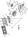
Fig. 2 shows the connection portion of thehandle 2. Thehandle 2 includes ahandle body 2A, acover 4, abutton 5 and aconnector 600. Thecover 4 is attached to thehandle body 2A from above (for example by snap fitting, or riveting, or any other suitable means). Thecover 4 can be fixed to thehandle body 2A permanently, or thecover 4 can be detachable from thehandle body 2A. Thecover 4 may include anopening 4A, in which the lower part of thebutton 5 is inserted. Especially, the lower part of thebutton 5 comprises aprojection 5A, which is received in theopening 4A, such that theprojection 5A projects inside ahollow portion 20 of thehandle body 2A. - The
hollow portion 20 inside thehandle body 2A is provided at the connection portion of thehandle 2, i.e. adjacent to thecartridge 3. At the bottom of thehollow portion 20, there is formed a substantiallyflat platform 21. The hollowedportion 20 includes anelastic tongue 7, which extends substantially along the longitudinal axis of thehandle 2. Theplatform 21 can be divided into a far side, being the side the most distant from thecartridge 3, a close side, being the side closer to thecartridge 3, and a middle area lying between the far side and the close side. The far side of theplatform 21, there projects anattachment portion 9. In the middle area of the platform there are located twostops 8. On each side of thehandle body 2A is located onestop 8. Thestops 8 are located next to theelastic tongue 7, eachstop 8 being positioned on the opposite side of thehandle body 2A with respect to theelastic tongue 7. At the close side of theplatform 21 there is adepression 10. Thedepression 10 can have a shape of a circle sector, where this circle has the center on the rotational axis Z. Generally, theconnector 600 is guided within thedepression 10. As a result, rotational movement of theconnector 600 with respect to thehandle body 2A results is enabled. -
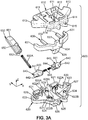
Fig. 3 shows an exploded view of theconnector 600. Theconnector 600 has preferably a substantially flat shape and extends generally in a connector plane XY. Theconnector 600 is adapted to rotate within the connector plane XY around a rotational axis Z. The rotational axis Z is perpendicular to the connector plane XY. The longitudinal axis L of thehandle 2 lies substantially within the connector plane XY. The rotational axis Z is thus also perpendicular to the longitudinal axis L of thehandle 2. The connector plane XY is parallel with the plane, in which theflat platform 21 extends. It is preferable that the pivot axis P lies within the connector plane XY, or the pivot axis P is parallel with the connector plane XY. Theconnector 600 is symmetrical along the plane YZ defined by the connector plane XY and the rotational axis Z. Theconnector 600 is also symmetrical with respect to plane LZ defined by the longitudinal axis L and the rotational axis Z. - The
connector 600 can be divided into acartridge end 600B and atongue end 600A, although both ends pertain to a single piece of material. Thecartridge end 600B of theconnector 600 has a shape complementary with the receivingaperture 41 of theintermediate component 40, such that thecartridge end 600B can be inserted into the receivingaperture 41. Theconnector 600 comprises atop part 610, abottom part 620, aslider 630 sandwiched between thetop part 610 and thebottom part 620, and a pair oflockers 640 also positioned between thetop part 610 and thebottom part 620, where all of these parts are symmetrical with respect to plane YZ. Thetop part 610 comprises a pair offlank sections 613, and a pair ofbody sections 614. Thebody sections 614 form the center of thetop part 610, and theflank sections 613 extend to the sides from eachrespective body section 614. Theflank sections 613 also extend forwardly towards thecartridge 3. The shape of the flank section is rounded. When viewed from the top (as illustrated for example onFigs. 6A and 6B ), the side of theflank sections 613 facing thecartridge 3 has a shape of a part of a circle having the center on the rotational axis. The side of theflank sections 613 opposite thecartridge 3 also has a shape of a part of a circle having center on the rotational axis. - The
top part 610 further comprises twoside channels 611 and acentral channel 612. Thecentral channel 612 extends along the longitudinal axis L of thehandle 2. Theside channels 611 each include a passage, which extends in the same direction as thecentral channel 612, and a passage which extends perpendicularly and towards to the longitudinal axis L. Theside channels 611 have generally the shape of letter P (or mirrored letter P). Eachside channel 611 is located on opposite side of thetop part 610 with respect to thecentral channel 612. Thetongue end 600A of theconnector 600 comprises arecess 615. On the bottom side of thetop part 610, there are fourprotrusions top part 610. There are fourprotrusions Fig. 3B . Twoprotrusions 616B are located at thetongue end 600A and twoprotrusions 616A are located at thecartridge end 600B, each pair positioned symmetrically with respect to thecentral channel 612. Theprotrusions bottom part 620, thus forming connection between thetop part 610 and thebottom part 620. As long as this function is fulfilled, the number ofprotrusions - The
bottom part 620, similarly to thetop part 610, also comprises a pair offlank sections 623 and a pair ofbody sections 624. When thehandle 2 is viewed from top (directions of the rotational axis Z) theflank sections 613 and thebody sections 614 of thetop part 610 overlap theflank sections 623 and thebody sections 624 of thebottom part 620. Similarly to thetop part 610, thebottom part 620 is also provided with arecess 625 at the tongue end 600A, therecess 625 of thebottom part 620 being overlapped by therecess 615 of thetop part 610, when viewed from top (in the direction of the rotational axis Z). Thebottom part 620 further comprises a set oftubes protrusions top portion 610. Thetubes protrusions top part 610 to thebottom part 620. Nevertheless, alternative attaching means can be used as well, such as welding or gluing. In that case, neither theprotrusions tubes - The
bottom part 620 may further comprise a pair of front faces 621 at the very tip of thecartridge end 600B. The front faces 621 extend upwardly from thebottom part 620. Downwards from thebottom part 620 at thetongue end 600A, there extends acavity 626. Thecavity 626 has form of a pocket and although thecavity 626 is part of theconnector 600, it is located generally below the connector plane XY. Thecavity 626 has a shape complementary with the shape of thedepression 10 in thehandle body 2A. Sliding of thecavity 626 within thedepression 10 results in the rotational movement of theconnector 600 with respect to thehandle body 2A. Thebottom part 620 may also comprise acentral groove 628, which extends from the base of thecavity 626 towards thecartridge end 600B. Thecentral groove 628 is adapted to guide apusher 650, which is part of theconnector 600. Alongside thecentral groove 628 at thecartridge end 600B of thebottom part 620, there are positioned twowalls 628A. There is onewall 628A on each side extending along thecentral groove 628. The walls 628B extend upwards from thebottom part 620. Further, there may beside grooves 629 located in theflank sections 623. Theside grooves 629 may extend parallel with the longitudinal axis L, and they may be adapted to guide some portions of theslider 630, as further explained below. - The
pusher 650 can comprise acam following section 651, arib 652 and anopening 653 for aspring 650A. Thecam following section 651 cooperates with the at least onecam surface 36 of thecartridge 3. When thecartridge 3 is pivoted about the pivot axis P, the cam surface(s) 36 force thepusher 650 to slide within thecentral groove 628 towards the inside of thehandle 2. As a result, thespring 650A is compressed, thus generating a return force biasing thepusher 650A back to its initial position, and thereby urging thecartridge 3 into the neutral position. Therib 652 of thepusher 650 is guided by thecentral channel 612 of thetop part 610. Wobbling of thepusher 650 in the central groove is thus prevented. Therib 652 may not have the same height along its entire length. Therib 652 may be stepped, including one lower portion and one higher portion. - The
slider 630 may be adapted to slide along the longitudinal axis L of thehandle 2. Theslider 630 is interposed between thetop part 610 and thebottom part 620. Theslider 630 may include aslider body 634, a pair ofouter arms 631 and a pair ofinner arms 632. Theouter arms 631 are guided in theside grooves 629 of the bottom part. The shape of theouter arms 631 is such that the outer arms can be placed in the area created by theflank portions connector 600. Theouter arms 631 thus extend generally sideways from theslider body 634, and then - towards the ends of the outer arms 631 - extend forwardly parallel with the longitudinal direction L of the handle towards thecartridge 3. Theinner arms 632 project forwardly substantially from the middle of theouter arms 631 parallel with the longitudinal direction L and towards thecartridge 3. The ends of theouter arms 631, which are the parts most distant from theslider body 634, are thus parallel with theinner arms 632. The inner arms are guided within theside channels 611 of thetop part 610, more particularly within the passage of theside channels 611, which extends parallel with the longitudinal axis L. Theslider 630 may also include a pair ofguides 636, which extend downwardly from theouter arms 631. Theguides 636 can be in the form of elongated ribs extending along the longitudinal axis L of thehandle 2. Theguides 636 are adapted to be received in thebottom channels 627 of thebottom part 620, so that the slider is conveniently retained in its desired position. Especially, theslider 630 is prevented from side-to-side movement. - The
slider 630 may further include anupper extension 633 projecting upwards from theslider body 634. Theupper extension 633 has such a shape, that it could be received in thecentral channel 612 of thetop part 610. Theslider 630 is thus supported by thetop part 610, and is prevented from moving sideways. The slider may further include alower extension 635 projecting downwards from theslider body 634. Thelower extension 635 is received in and guided by thecavity 626 of thebottom part 620. Thelower extension 635 abuts with and functionally cooperates with thespring 650A. Thespring 650A is generally positioned between the interior face of theopening 653 and thelower extension 635, as illustrated onFig. 5 . When theslider 630 is moved forward towards thecartridge 3, thespring 650A is contracted and urges thepusher 650 to exert pushing force on the cam surface(s) 36 of thecartridge 3. -
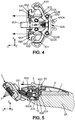
Fig. 4 shows that thelockers 640 are located at thecartridge end 600B of theconnector 600. Thelockers 640 may be aligned with the front faces 621 of thebottom part 620. Thelockers 640 are adapted to slide perpendicular to the longitudinal axis L. The bottom side of the lockers may be provided with projections, which may be adapted to fit in a complementary features in thebottom part 620, such as suitable pair of grooves. Thelockers 640 are generally restricted from movement along the longitudinal axis L. Thelockers 640 are movable in a direction towards and away from each other (direction of axis X). Thelockers 640 may further be guided in theside channels 611 of thetop part 610, more particularly, thelockers 640 are guided in those passages of the side channels, which extend perpendicularly to the longitudinal axis L. Eachlocker 640 comprises apin 642 extending outwardly along the axis X. Thepins 642 are adapted to be received in the respective hole (not shown on the drawings) of theintermediate component 40 located inside the receiving aperture. When thepins 642 of thelockers 640 are engaged in the hole of the receivingaperture 41, the intermediate component 40 (and therefore also the cartridge 3) is engaged with thehandle 2. Thepins 642 are aligned with the front faces 621 of thebottom part 620, more particularly, thepins 642 slide along the front faces 621. - The
lockers 640 further include aridge 643. Initially, one end of theridge 643 is in contact with a corresponding end of the correspondinginner arm 632. From the point of contact with theinner arm 632, theridge 643 extends forwardly and sideways, such that it forms an angle with the longitudinal axis L of thehandle 2. The angle between theridge 643 and the longitudinal axis L may be 15-45°, and preferably 35° or 40°. When theslider 630 slides forwardly towards thecartridge 3, the ends of theinner arms 631 move along theridges 643, thereby forcing thelockers 640 to slide towards each other (i.e. in the direction towards the pusher 650). Once thelockers 640 are forced to slide towards each other, thepins 642 are disengaged from the holes (not shown on the drawings) of the receivingaperture 41, and thehandle 2 is disengaged from the intermediated component 40 (and therefore also from the cartridge 3). - The
lockers 640 may further include anopening 644 for alocker spring 645. Eachlocker spring 645 may extend between the interior face of theopening 644 and therespective wall 628A, which extends alongside thecentral groove 628. When thelockers 640 are pushed towards each other by theinner arms 632, the locker springs 645 get compressed, thereby generating a return force, urging thelockers 640 back into their initial position. The biasing force of thelocker spring 645 is also applied through thelockers 640 onto theslider 630. Theslider 630 is thus also partially urged into its initial position by the locker springs 645. When theslider 630 is moved forwards, thespring 650A gets also contracted, thus forcing theslider 630 back into its initial position. Thespring 650 A has thus two functions. On one hand, it generates biasing force returning pivotedcartridge 3 into the neutral position, and on the other hand, it also generates biasing force returning theslider 630 into its initial position, after theslider 630 is slid forwards. -
Fig. 5 illustrates that the handle is provided with abutton 5, which is slidable along the longitudinal axis L of thehandle 2. The button is positioned on thecover 4. Thebutton 5 comprises aprojection 5A projecting through theopening 4A in the cover inside thehandle body 2A. Theprojection 5A abuts with theupper extension 633 of theslider 630. When the user decides to replace shavingcartridge 3, he/she may slide thebutton 5 forward with his/her finger in the direction of the arrow A. As thebutton 5 is slid forward, theslider 630 is also slid forward. Thelockers 640 are moved towards each other, thereby disengaging thepins 642 from the holes of the receivingaperture 41. Theconnector 600 is thus disconnected from the intermediatedcomponent 40. As a result, thecartridge 3 is disconnected from thehandle 2. - The
intermediate component 40 and theconnector 600 can alternatively be provided in a single piece. In this embodiment, thecartridge 3 is not replaceable and the features related to unlocking the connection between thehandle 2 and the cartridge 3 (or more particularly between the intermediatedcomponent 40 and the connector 600) are omitted. Therefore, thebutton 5, theopening 4A, theslider 630, and thelockers 640 are omitted. - In the preferred embodiments, the
connector 600, the intermediatedcomponent 40 and thecartridge 3 are adapted to rotate about the rotational axis Z. The rotation of theconnector 600 about the rotational axis Z is enabled by thecavity 626 being positioned in thedepression 10, such that thecavity 626 can slide along the rounded walls of thedepression 10. Theintermediate component 40 is engaged with theconnector 600 by means of thelockers 640 and the holes located inside the receivingaperture 41, thus the rotation of theconnector 600 causes simultaneous rotation of theintermediate component 40. Theintermediate component 40 is attached to the cartridge 3 (either directly to thehousing 39, or to theback structure 35 if present). Therefore, when theintermediate component 40 rotates about the rotational axis Z, thecartridge 3 rotates as well. The connection between theintermediate component 40 and thecartridge 3 further enables pivoting movement about another axis, the pivot axis P. - The rotational axis Z is preferably located such that it intersects the
cartridge 3. Even more preferably, the rotational axis Z can intersect the cutting plane defined by the cutting edges 32 of theblades 31. The cutting plane is the plane, which is tangent to the plurality of cuttingedges 32, i.e. the cutting plane has one point of contact with each of the cutting edges 32 present in thecartridge 3. The rotational axis Z may also directly intersect with one of the cutting edges 32. The distance between the rotational axis Z and theclosest cutting edge 32 is preferably not more than 1 mm, and even more preferably not more than 0.5 mm. The rotational axis Z is preferably perpendicular to the longitudinal axis L of thehandle 2. The rotational axis Z is perpendicular to the connector plane XY. The rotational axis Z and the pivot axis P preferably intersect each other, such that they both lie in a common plane ZP. The rotational axis Z and the pivot axis P may preferably intersect directly in the shaving plane S. Nevertheless, other configurations are possible as well, namely configuration where the intersection of the rotational axis Z and the pivot axis P is located above or below the shaving plane S. - The pivot axis P is preferably parallel with the connector plane XY, for example, the pivot axis may lie in the connector plane XY. The pivot axis P preferably intersects the
cartridge 3. The pivot axis P can be parallel with the blade edge axis B of thecutting edge 32 of the at least oneblade 31. The pivot axis P may lie in the cutting plane, or in some embodiments the pivot axis P can be identical with a blade edge axis B (when the shaver 1 is assembled and thecartridge 3 is in neutral position). -
Fig. 6A shows theconnector 600 in the rest position. Theconnector 600 is rotatable in both directions indicated by the arrow F. In the rest position, theflank sections hollow portion 20, i.e. covered from below by thehandle body 2A, and covered from above by thecover 4. When theconnector 600 is rotated about the rotational axis Z, thecorresponding flank sections hollow portion 20. During the rotation of theconnector 600, theflank sections handle body 2A located at the end of the connector portion of the handle 2 (as is apparent fromFig. 6B ). -
Fig. 6B shows theconnector 600 in a rotated position. Theconnector 600 is rotated about an angle of rotation R, with respect to the longitudinal axis L. Theconnector 600 generally rotates between a first extreme rotated position and a second extreme rotated position. In each of the first and second extreme positions, the correspondingbody sections connector 600. As theconnector 600 is rotated towards one of the first or second extreme rotated positions, theelastic tongue 7 is flexed. The flexion of theelastic tongue 7 generates a return torgue force urging theconnector 600 back into its rest position. When theconnector 600 is rotated to the left, theelastic tongue 7 is flexed also to the left. When theconnector 600 is rotated to the right, theelastic tongue 7 is flexed also to the right. Flexing of theelastic tongue 7 is only allowed within the area defined by the twostops 8, which prevent the elastic tongue from flexing too much. - The return torque generated by the
elastic tongue 7 lies between 0 N.mm and 30 N.mm, preferably between 10 and 30 N.mm, and even more preferably between 15 N.mm and 25 N.mm. The return toque exerted by theelastic tongue 7 increases, as theconnector 600 is rotated to either side. The increase of the return toque may depend on the angle of rotation R of theconnector 600 either linearly or nonlinearly. The increase of the return toque per degree may lie between 0.5 N.mm and 2 N.mm, preferably between 0.67 N.mm and 2 N.mm, and even more preferably between 1 N.mm and 1.67 N.mm. - The values of the return toque defined in the preceding paragraph are measured in the following manner. The
cartridge 3 is pivoted about the pivot axis X into the fully pivoted position, where it is kept during the entire time of measuring. A testing force E is applied on a point of the front surface of thecartridge 3, where the cutting edges 32 are located. The point on which the force E is applied lies substantially in the shaving plane S. As illustrated onFig. 6A , the testing force E is applied perpendicular to the shaving plane S. The testing force E is applied at a selected distance M with respect to the plane of symmetry of thecartridge 3, this plane of symmetry being identical with plane LZ onFig. 6A . Because of the testing force E, the connector (600) is rotated about a concrete angle of rotation R. - The distance M between the plane LZ and the point of application of the testing force E corresponds to a moment arm. By multiplying the value of the moment arm M with the value of the testing force E one obtains the value of the return torque exerted by the elastic tongue (7) for the particular situation, where the connector (600) is rotated about the concrete angle of rotation R. In this way, the values of return toque can be measured for an arbitrary angle of rotation R.
-
Fig. 7 shows that the elastic tongue comprises a first end 7A and asecond end 7B. Theelastic tongue 7 may be made of plastic or metal, or other suitable flexible material. Theattachment portion 9 fixes the first end 7A of theelastic tongue 7 to thehandle body 2A. In alternative embodiments, theelastic tongue 7 may be integral part of thehandle body 2A. Thesecond end 7B of theelastic tongue 7 is freely movable within the borders defined by thestops 8. More particularly, thesecond end 7B of theelastic tongue 7 flexes towards a first extreme flexed position as theconnector 600 rotates towards the first extreme rotated position, and thesecond end 7B of theelastic tongue 7 flexes towards a second extreme flexed position as theconnector 600 rotates towards the second extreme rotated position, such that the flexedelastic tongue 7 biases theconnector 600 towards the rest position. Thesecond end 7B is inserted into therecess - When not flexed, the
elastic tongue 7 is substantially linear and extends along the longitudinal axis L of thehandle 2. Theelastic tongue 7 may have any suitable shape. For example, the elastic tongue may be in the form of spring (such as helical spring, or torsion spring). Theelastic tongue 7 may advantageously have a form of an elastic sheet as is visible onFig. 5 showing the elastic tongue from a side. The elastic sheet may extend in the plane ZY. The elastic sheet can have any shape, preferably a substantially rectangular shape, the longer side of the rectangle (extending along the Y-axis) being parallel with the longitudinal axis L, and the shorter side (extending along the Z-axis) of the rectangle being perpendicular to the longitudinal axis L. The dimension of theelastic tongue 7 along the Z-axis may be between 2.5 and 3.5 mm, for example 3 mm. The dimension of theelastic tongue 7 along the Y-axis may be between 18 mm and 25 mm, for example 19 mm, 21 mm or 23 mm. The elastic tongue in the form of an elastic sheet may have a thickness T corresponding to the dimension taken along the X-axis. The average thickness of theelastic tongue 7 could be between 0.6 mm and 0.8 mm, for example 0.7 mm. - The
second end 7B of the elastic tongue may comprise any shape, preferably an oval portion 7C. The oval portion 7C having an oval shape in the cross-section taken in a plane parallel with the connector plane XY. The oval portion 7C may be in the form of an ellipse with a major axis extending along the longitudinal axis L of thehandle 2 and the minor axis extending within a plane parallel with the connector plane XY. - The thickness T of the
elastic tongue 7 at thefirst end 7B may be greater than the thickness T of theelastic tongue 7 at thesecond end 7B. The thickness T may continuously decrease from the first end 7A towards thesecond end 7B (this being true with the exception of the oval portion 7C, which forms a special part of the elastic tongue). Ratio between the thickness T of the first end 7A of theelastic tongue 7 and thesecond end 7B of theelastic tongue 7 can be anywhere between 1:1 and 2:1, for example 1.5:1. Ratio between thickness of the first end of theelastic tongue 7 without the considering the oval portion 7C and the maximum thickness T of the oval portion of theelastic tongue 7 may be between 0.6:1 and 0.9:1, for example 0.75:1. Ratio between thickness T of the portion of thesecond end 7B of theelastic tongue 7 neighbouring with the oval portion 7C and the maximum thickness of the oval portion may be between 0.4:1 and 0.6:1, for example 0.5:1. - The
recess second end 7B of theelastic tongue 7 and the inner surface of therecess second end 7B is not fixedly fitted in therecess recess recess wings recess wings handle 2, and each wing defines a planar surface W, such that the respective planar surfaces W of the pair ofwings handle 2. Each planar surface W of the pair ofwings handle 2, for example this angle can be 40° or 50°.
Claims (15)
- A handle (2) for a shaver (1) comprising:a handle body (2A) including hand gripping portion and extending along a longitudinal axis (L) of the handle (2);a connector (600) for attaching a cartridge (3) to the handle (2), said connector (600) being rotatable with respect to the handle body (2A) around a rotational axis (Z) perpendicular to the longitudinal axis (L) of the handle from a rest position and between a first extreme rotated position and a second extreme rotated position;an elastic tongue (7) extending parallel with the longitudinal axis (L) of the handle, when in neutral position,;wherein the elastic tongue (7) includes a first end (7A) and a second end (7B),wherein the second end (7B) of the elastic tongue (7) flexes towards a first extreme flexed position as the connector (600) rotates towards the first extreme rotated position, and the second end (7B) of the elastic tongue (7) flexes towards a second extreme flexed position as the connector rotates towards the second extreme rotated position, such that the flexed elastic tongue biases the connector (600) towards the rest position,characterized in that
the connector (600) includes a cartridge end and a tongue end opposite to the cartridge end, the cartridge end of the connector being adapted to engage with the cartridge (3),
and in that the first end (7A) of the elastic tongue (7) is fixedly attached to or integral with the handle body (2A). - The handle (2) according to claim 1, wherein said connector (600) extends in a connector plane (XY) parallel with the longitudinal axis (L) of the handle
- The handle (2) according to any one of claims 1-2, wherein the rotational axis (Z) is perpendicular to the connector plane (XY).
- The handle (2) according to any one of the preceding claims,
wherein the tongue end of the connector (600) comprises a recess (615, 625) having a rounded shape in a cross-section taken in a plane parallel with the connector plane (XY). - The handle (2) according to any one of the preceding claims,
wherein the elastic tongue (7) has the form of an elastic sheet, said sheet extending in a plane perpendicular with the connector plane (XY); and
wherein thickness of the elastic sheet decreases from the first end (7A) of the elastic tongue towards the second end (7B) of the elastic tongue. - The handle (2) according to any one of claims 4-9,
wherein a pair of wings (615A, 625A) extends outwardly from each side of the recess (615, 625) and outwardly from each other,
wherein the pair of wings (615A, 625A) is symmetrical along the longitudinal axis (L) of the handle (2), and
wherein each wing (615A, 625A) defines a planar surface (W), such that the planar surfaces (W) of the pair of wings (615A, 625A) form a V-arrangment symmetrical with respect to the longitudinal axis L of the handle (2). - The handle (2) according to claim 6,
wherein each planar surface (W) of the pair of wings (615A, 625A) forms an angle between 30-60° with the longitudinal axis (L) of the handle. - The handle (2) according to any one of the preceding claims,
wherein the handle body (2A) comprises a pair of stops (8), such that each stop (8) is respectively adapted to prevent the elastic tongue (7) to move beyond either the first extreme flexed position or the second extreme flexed position. - A shaver (1) comprising the handle according to any one of the preceding claims, the shaver further comprising:a cartridge (3) carrying at least one blade (31) having a blade edge (32) and extending along a blade edge axis (B).
- The handle (2) according to any one of the preceding claims, wherein the elastic tongue (7), when flexed, generates a return torque between 0 N.mm and 30 N.mm.
- The handle (2) according to any one of the preceding claims, wherein upon increasing angle of rotation (R) of the connector (600), the elastic tongue (7) generates an increasing return torque, wherein the increase of the return torque per degree of rotation lies between 0.5 N.mm and 2 N.mm.
- The shaver (1) according to claim 9,
wherein the rotational axis (Z) and pivot axis (P) are perpendicular to each other. - The shaver (1) according any one of claims 9-10,
wherein the rotational axis (Z) and the pivot axis (P) intersect each other. - The shaver (1) according to any one of claims 9-11,
wherein the rotational axis (Z) intersects at least one cutting edge (32) of the at least one blade (31). - The shaver (1) according to any one of claims 13-16,
wherein the cartridge (3) is pivotable about a pivot axis (P) parallel to the blade edge axis (B).
Priority Applications (20)
| Application Number | Priority Date | Filing Date | Title |
|---|---|---|---|
| EP17151799.8A EP3348364B1 (en) | 2017-01-17 | 2017-01-17 | A handle for a shaver enabling rotational movement of a cartridge |
| EP18700649.9A EP3571025B1 (en) | 2017-01-17 | 2018-01-10 | A connector adapted for wet shaving cartridges pivotable about two axes |
| BR112019014564-8A BR112019014564B1 (en) | 2017-01-17 | 2018-01-10 | SHAVING HANDLE AND SHAVING SYSTEM |
| CA3047207A CA3047207A1 (en) | 2017-01-17 | 2018-01-10 | A connector adapted for wet shaving cartridges pivotable about two axes |
| MX2019008400A MX2019008400A (en) | 2017-01-17 | 2018-01-10 | A handle for a shaver enabling rotational movement of a cartridge. |
| JP2019536833A JP2020505096A (en) | 2017-01-17 | 2018-01-10 | Handle for shaver that enables rotational movement of cartridge |
| KR1020197020958A KR20190103216A (en) | 2017-01-17 | 2018-01-10 | Handle for shaver to allow cartridge to rotate |
| PCT/EP2018/050595 WO2018134104A1 (en) | 2017-01-17 | 2018-01-10 | A handle for a shaver enabling rotational movement of a cartridge |
| CN201880006256.XA CN110248779B (en) | 2017-01-17 | 2018-01-10 | Connector suitable for a wet shaving head pivotable about two axes |
| RU2019119959A RU2757043C2 (en) | 2017-01-17 | 2018-01-10 | Connector designed for wet shaving cartridges made with the possibility of rotation around two axes |
| RU2019118225A RU2753231C2 (en) | 2017-01-17 | 2018-01-10 | Razor handle that allows cartridge to rotate |
| BR112019014565-6A BR112019014565B1 (en) | 2017-01-17 | 2018-01-10 | HANDLE FOR A SHAVOR AND SHAVING APPARATUS |
| US16/478,527 US11597110B2 (en) | 2017-01-17 | 2018-01-10 | Handle for a shaver enabling rotational movement of a cartridge |
| JP2019536923A JP2020503954A (en) | 2017-01-17 | 2018-01-10 | Connector adapted for wet shaving cartridge pivotable about two axes |
| US16/478,522 US11298843B2 (en) | 2017-01-17 | 2018-01-10 | Shaving cartridges pivotable about two axes |
| KR1020197020960A KR20190103218A (en) | 2017-01-17 | 2018-01-10 | Connector for wet shaving cartridge that can pivot about 2 axes |
| PL18700649T PL3571025T3 (en) | 2017-01-17 | 2018-01-10 | A connector adapted for wet shaving cartridges pivotable about two axes |
| PCT/EP2018/050594 WO2018134103A1 (en) | 2017-01-17 | 2018-01-10 | A connector adapted for wet shaving cartridges pivotable about two axes |
| MX2019008402A MX2019008402A (en) | 2017-01-17 | 2018-01-10 | A connector adapted for wet shaving cartridges pivotable about two axes. |
| CN201880005674.7A CN110234475B (en) | 2017-01-17 | 2018-01-10 | Handle for a shaver enabling a rotational movement of a shaving head |
Applications Claiming Priority (1)
| Application Number | Priority Date | Filing Date | Title |
|---|---|---|---|
| EP17151799.8A EP3348364B1 (en) | 2017-01-17 | 2017-01-17 | A handle for a shaver enabling rotational movement of a cartridge |
Publications (2)
| Publication Number | Publication Date |
|---|---|
| EP3348364A1 true EP3348364A1 (en) | 2018-07-18 |
| EP3348364B1 EP3348364B1 (en) | 2020-04-15 |
Family
ID=57838237
Family Applications (1)
| Application Number | Title | Priority Date | Filing Date |
|---|---|---|---|
| EP17151799.8A Active EP3348364B1 (en) | 2017-01-17 | 2017-01-17 | A handle for a shaver enabling rotational movement of a cartridge |
Country Status (8)
| Country | Link |
|---|---|
| US (1) | US11597110B2 (en) |
| EP (1) | EP3348364B1 (en) |
| JP (1) | JP2020505096A (en) |
| KR (1) | KR20190103216A (en) |
| CN (1) | CN110234475B (en) |
| MX (1) | MX2019008400A (en) |
| RU (1) | RU2753231C2 (en) |
| WO (1) | WO2018134104A1 (en) |
Families Citing this family (18)
| Publication number | Priority date | Publication date | Assignee | Title |
|---|---|---|---|---|
| KR101703508B1 (en) * | 2015-11-20 | 2017-02-07 | 주식회사 도루코 | Handle assembly of razor and razor including the same |
| CA3047207A1 (en) | 2017-01-17 | 2018-07-26 | Bic-Violex Sa | A connector adapted for wet shaving cartridges pivotable about two axes |
| PL3348363T3 (en) * | 2017-01-17 | 2020-01-31 | Bic-Violex S.A. | A shaving handle system for holding a cartridge pivotable about two axes |
| EP3348364B1 (en) | 2017-01-17 | 2020-04-15 | BIC-Violex S.A. | A handle for a shaver enabling rotational movement of a cartridge |
| WO2019108392A1 (en) * | 2017-11-28 | 2019-06-06 | Edgewell Personal Care Brands, Llc | Razor handle |
| EP3546156B1 (en) | 2018-03-30 | 2021-03-10 | The Gillette Company LLC | Razor handle with a pivoting portion |
| WO2019191163A1 (en) | 2018-03-30 | 2019-10-03 | The Gillette Company Llc | Razor handle with a pivoting portion |
| BR112020020132A2 (en) * | 2018-03-30 | 2021-01-05 | The Gillette Company Llc | HANDLE OF SHAVING OR DEVILING APPLIANCE WITH MOBILE LIMBS |
| USD874061S1 (en) | 2018-03-30 | 2020-01-28 | The Gillette Company Llc | Shaving razor cartridge |
| WO2019191178A1 (en) | 2018-03-30 | 2019-10-03 | The Gillette Company Llc | Razor handle with movable members |
| EP3774230A1 (en) | 2018-03-30 | 2021-02-17 | The Gillette Company LLC | Razor handle with a pivoting portion |
| US11607820B2 (en) | 2018-03-30 | 2023-03-21 | The Gillette Company Llc | Razor handle with movable members |
| JP2021516102A (en) | 2018-03-30 | 2021-07-01 | ザ ジレット カンパニー リミテッド ライアビリティ カンパニーThe Gillette Company Llc | Razor handle with pivot part |
| CA3091484A1 (en) * | 2018-03-30 | 2019-10-03 | The Gillette Company Llc | Shaving razor system including skin interconnect member |
| EP3623121B1 (en) | 2018-09-14 | 2022-02-16 | BIC-Violex S.A. | Razor handle and razor assembly |
| EP3666479B1 (en) * | 2018-12-14 | 2024-01-24 | BIC Violex Single Member S.A. | Blade assembly attachment mechanism and modular razor assembly |
| KR102231870B1 (en) * | 2019-07-08 | 2021-03-25 | 주식회사 도루코 | Cartridge Connector and Razor Assembly Using the Same |
| EP3842196B1 (en) * | 2019-12-23 | 2023-09-13 | BIC Violex Single Member S.A. | Coupling mechanism |
Citations (6)
| Publication number | Priority date | Publication date | Assignee | Title |
|---|---|---|---|---|
| US3935639A (en) * | 1973-03-01 | 1976-02-03 | The Gillette Company | Safety razor |
| US5029391A (en) * | 1989-03-15 | 1991-07-09 | Wilkinson Sword Gesellschaft Mit Beschrankter Haftung | Pivot-head razor |
| EP1245351A1 (en) * | 2001-03-28 | 2002-10-02 | Warner-Lambert Company | Safety razor comprising pivoted pivot assembly and pivoted blade assembly |
| GB2463035A (en) * | 2008-08-29 | 2010-03-03 | James Bartholomew Philpotts | Manual shaving razor with damping elastic elements |
| EP2508309A1 (en) | 2011-04-05 | 2012-10-10 | The Gillette Company | Razor handle with a rotatable portion |
| DE102013213881A1 (en) * | 2013-07-16 | 2015-01-22 | Beiersdorf Ag | Razor with free movement of the razor head |
Family Cites Families (41)
| Publication number | Priority date | Publication date | Assignee | Title |
|---|---|---|---|---|
| US2119792A (en) * | 1935-06-01 | 1938-06-07 | Theodore W Foster & Bro Co | Razor with adjustable handle |
| US3950848A (en) | 1974-03-18 | 1976-04-20 | Michael Goldstein | Safety razor |
| US3950849A (en) | 1974-07-23 | 1976-04-20 | The Gillette Company | Razor with rotatably mounted shaving unit |
| US3964160A (en) | 1975-04-02 | 1976-06-22 | Garron Gordon | Safety razor with an angularly adjustable head |
| US4152828A (en) | 1978-03-29 | 1979-05-08 | Lund Lloyd W | Razor having variable angle and tilt of its blade |
| JPS596675B2 (en) | 1980-10-20 | 1984-02-14 | 株式会社貝印刃物開発センター | safety razor |
| US4403414A (en) | 1981-04-09 | 1983-09-13 | Warner-Lambert Company | Socket device for a pivotal razor |
| GB2116470B (en) | 1982-03-12 | 1985-09-25 | Gillette Co | Safety razors |
| US4879811A (en) | 1987-10-01 | 1989-11-14 | Cooney Daniel J | Safety razor |
| AR244587A1 (en) | 1989-11-17 | 1993-11-30 | Warner Lambert Co | Pivoting safety razor assembly |
| JPH0422388A (en) | 1990-05-18 | 1992-01-27 | Kaijirushi Hamono Kaihatsu Center:Kk | Safety shaver |
| US5050301A (en) | 1990-09-19 | 1991-09-24 | The Gillette Company | Razor assembly |
| GB9208098D0 (en) | 1992-04-13 | 1992-05-27 | Gillette Co | Razor with movable cartridge |
| US5953824A (en) | 1997-09-23 | 1999-09-21 | Warner-Lambert Company | Razors providing pivoting and swivelling razor head support |
| US6615498B1 (en) | 2000-03-13 | 2003-09-09 | Warner-Lambert Company | Flexible member for a shaving razor |
| US7137205B2 (en) | 2002-10-01 | 2006-11-21 | The Gillette Company | Linkage mechanism providing a virtual pivot axis for razor apparatus with pivotal head |
| JP3972903B2 (en) | 2003-12-26 | 2007-09-05 | 松下電工株式会社 | Electric razor |
| EP1789238B1 (en) | 2004-09-07 | 2008-03-19 | BIC Violex S.A. | Razor handle and shaver including such a handle |
| US7526869B2 (en) | 2006-06-08 | 2009-05-05 | Eveready Battery Company, Inc. | Razor handle |
| US7461458B2 (en) | 2006-06-14 | 2008-12-09 | Eveready Battery Company, Inc. | Wet shaving razor |
| US8205344B2 (en) * | 2008-08-20 | 2012-06-26 | The Gillette Company | Safety razor having pivotable blade unit |
| KR101486932B1 (en) | 2008-10-01 | 2015-01-27 | 빅-비올렉스 에스아 | Razor handles to be realeasably connected to shaving cartridges and razors including such handles |
| CN102574287B (en) | 2009-07-31 | 2014-12-10 | 比克-维尔莱克 | Wet shaver |
| US20110247217A1 (en) | 2010-04-12 | 2011-10-13 | Robert Harold Johnson | Shaving cartridge having a front pivoting hood with a biasing member |
| US8898909B2 (en) | 2010-08-25 | 2014-12-02 | Spectrum Brands, Inc. | Electric shaver |
| US8745882B2 (en) * | 2010-09-29 | 2014-06-10 | The Gillette Company | Flexible and separable portion of a razor handle |
| US8745883B2 (en) * | 2010-09-29 | 2014-06-10 | The Gillette Company | Razor handle with a rotatable portion |
| US20130081290A1 (en) | 2011-10-03 | 2013-04-04 | Matthew Frank Murgida | Razor handle with a rotatable portion |
| US9707688B2 (en) | 2012-12-21 | 2017-07-18 | Bic Violex S.A. | Shaver |
| ES2660443T3 (en) | 2014-01-31 | 2018-03-22 | Feintechnik Gmbh Eisfeld | Razor with a handle and a rotating cutting unit |
| US11148310B2 (en) | 2014-03-24 | 2021-10-19 | Flexhandle, L.L.C. | Razor with handle having articulable joint |
| WO2018007134A1 (en) | 2016-07-06 | 2018-01-11 | Bic-Violex Sa | Shaving component, shaving cartridge, and method of manufacture |
| US9993931B1 (en) | 2016-11-23 | 2018-06-12 | Personal Care Marketing And Research, Inc. | Razor docking and pivot |
| PL3348363T3 (en) | 2017-01-17 | 2020-01-31 | Bic-Violex S.A. | A shaving handle system for holding a cartridge pivotable about two axes |
| CA3047207A1 (en) * | 2017-01-17 | 2018-07-26 | Bic-Violex Sa | A connector adapted for wet shaving cartridges pivotable about two axes |
| EP3348364B1 (en) | 2017-01-17 | 2020-04-15 | BIC-Violex S.A. | A handle for a shaver enabling rotational movement of a cartridge |
| KR101894213B1 (en) | 2017-11-21 | 2018-09-04 | 주식회사 도루코 | Razor assembly |
| KR101887119B1 (en) | 2017-11-21 | 2018-08-09 | 주식회사 도루코 | Razor assembly |
| CN109807949B (en) | 2017-11-21 | 2021-05-25 | 株式会社多乐可 | Razor assembly |
| EP3647003B1 (en) | 2018-10-31 | 2022-03-09 | Bic Violex S.A. | Razor handle with suspension and pivot device |
| US11161263B2 (en) | 2019-08-22 | 2021-11-02 | Harry's, Inc. | Razor cartridge connection and handle |
-
2017
- 2017-01-17 EP EP17151799.8A patent/EP3348364B1/en active Active
-
2018
- 2018-01-10 RU RU2019118225A patent/RU2753231C2/en active
- 2018-01-10 MX MX2019008400A patent/MX2019008400A/en unknown
- 2018-01-10 CN CN201880005674.7A patent/CN110234475B/en active Active
- 2018-01-10 US US16/478,527 patent/US11597110B2/en active Active
- 2018-01-10 JP JP2019536833A patent/JP2020505096A/en active Pending
- 2018-01-10 WO PCT/EP2018/050595 patent/WO2018134104A1/en active Application Filing
- 2018-01-10 KR KR1020197020958A patent/KR20190103216A/en not_active Application Discontinuation
Patent Citations (6)
| Publication number | Priority date | Publication date | Assignee | Title |
|---|---|---|---|---|
| US3935639A (en) * | 1973-03-01 | 1976-02-03 | The Gillette Company | Safety razor |
| US5029391A (en) * | 1989-03-15 | 1991-07-09 | Wilkinson Sword Gesellschaft Mit Beschrankter Haftung | Pivot-head razor |
| EP1245351A1 (en) * | 2001-03-28 | 2002-10-02 | Warner-Lambert Company | Safety razor comprising pivoted pivot assembly and pivoted blade assembly |
| GB2463035A (en) * | 2008-08-29 | 2010-03-03 | James Bartholomew Philpotts | Manual shaving razor with damping elastic elements |
| EP2508309A1 (en) | 2011-04-05 | 2012-10-10 | The Gillette Company | Razor handle with a rotatable portion |
| DE102013213881A1 (en) * | 2013-07-16 | 2015-01-22 | Beiersdorf Ag | Razor with free movement of the razor head |
Also Published As
| Publication number | Publication date |
|---|---|
| CN110234475A (en) | 2019-09-13 |
| KR20190103216A (en) | 2019-09-04 |
| US20200039098A1 (en) | 2020-02-06 |
| US11597110B2 (en) | 2023-03-07 |
| WO2018134104A1 (en) | 2018-07-26 |
| JP2020505096A (en) | 2020-02-20 |
| RU2753231C2 (en) | 2021-08-12 |
| BR112019014565A2 (en) | 2020-02-18 |
| EP3348364B1 (en) | 2020-04-15 |
| CN110234475B (en) | 2022-06-03 |
| RU2019118225A (en) | 2021-02-19 |
| MX2019008400A (en) | 2019-09-16 |
| RU2019118225A3 (en) | 2021-06-07 |
Similar Documents
| Publication | Publication Date | Title |
|---|---|---|
| EP3348364B1 (en) | A handle for a shaver enabling rotational movement of a cartridge | |
| EP3486048B1 (en) | Razor assembly | |
| EP3348363B1 (en) | A shaving handle system for holding a cartridge pivotable about two axes | |
| EP1635998B1 (en) | Razor having a multi-position shaving head | |
| US9032627B2 (en) | Shaving blade unit and shaver having such a blade unit | |
| US8359751B2 (en) | Shaving blade unit comprising a movable trimming blade protector and shaver having such a blade unit | |
| US7937837B2 (en) | Razor head having two shaving heads | |
| US20190263011A1 (en) | Shaving blade cartridge and a shaver comprising such shaving blade cartridge | |
| WO2005090016A1 (en) | Razor having two silideable shaving heads | |
| RU2693970C2 (en) | Cassette with shaving razors and shaver containing such cassette with razors for shaving | |
| US3955277A (en) | Adjustable razor blade unit | |
| US5784785A (en) | Folding longitudinal razor | |
| US20170106549A1 (en) | Shaving blade cartridge and a shaver comprising such shaving blade cartridge | |
| US6430814B1 (en) | Flexy razor using finger-assisted bending | |
| US11090825B2 (en) | Shaving cartridge | |
| US6247234B1 (en) | Razor and blade | |
| BR112019014565B1 (en) | HANDLE FOR A SHAVOR AND SHAVING APPARATUS | |
| CN110505949B (en) | Hair cutter and hair cutting blade | |
| US20240083051A1 (en) | Razor heads, kits, razors & methods comprising the same | |
| JP4504676B2 (en) | Hair cutter | |
| CN111051021A (en) | Shaving device |
Legal Events
| Date | Code | Title | Description |
|---|---|---|---|
| PUAI | Public reference made under article 153(3) epc to a published international application that has entered the european phase |
Free format text: ORIGINAL CODE: 0009012 |
|
| STAA | Information on the status of an ep patent application or granted ep patent |
Free format text: STATUS: THE APPLICATION HAS BEEN PUBLISHED |
|
| AK | Designated contracting states |
Kind code of ref document: A1 Designated state(s): AL AT BE BG CH CY CZ DE DK EE ES FI FR GB GR HR HU IE IS IT LI LT LU LV MC MK MT NL NO PL PT RO RS SE SI SK SM TR |
|
| AX | Request for extension of the european patent |
Extension state: BA ME |
|
| STAA | Information on the status of an ep patent application or granted ep patent |
Free format text: STATUS: REQUEST FOR EXAMINATION WAS MADE |
|
| 17P | Request for examination filed |
Effective date: 20190118 |
|
| RBV | Designated contracting states (corrected) |
Designated state(s): AL AT BE BG CH CY CZ DE DK EE ES FI FR GB GR HR HU IE IS IT LI LT LU LV MC MK MT NL NO PL PT RO RS SE SI SK SM TR |
|
| GRAP | Despatch of communication of intention to grant a patent |
Free format text: ORIGINAL CODE: EPIDOSNIGR1 |
|
| STAA | Information on the status of an ep patent application or granted ep patent |
Free format text: STATUS: GRANT OF PATENT IS INTENDED |
|
| INTG | Intention to grant announced |
Effective date: 20191122 |
|
| GRAS | Grant fee paid |
Free format text: ORIGINAL CODE: EPIDOSNIGR3 |
|
| GRAA | (expected) grant |
Free format text: ORIGINAL CODE: 0009210 |
|
| STAA | Information on the status of an ep patent application or granted ep patent |
Free format text: STATUS: THE PATENT HAS BEEN GRANTED |
|
| AK | Designated contracting states |
Kind code of ref document: B1 Designated state(s): AL AT BE BG CH CY CZ DE DK EE ES FI FR GB GR HR HU IE IS IT LI LT LU LV MC MK MT NL NO PL PT RO RS SE SI SK SM TR |
|
| REG | Reference to a national code |
Ref country code: CH Ref legal event code: EP |
|
| REG | Reference to a national code |
Ref country code: DE Ref legal event code: R096 Ref document number: 602017014606 Country of ref document: DE |
|
| REG | Reference to a national code |
Ref country code: IE Ref legal event code: FG4D |
|
| REG | Reference to a national code |
Ref country code: AT Ref legal event code: REF Ref document number: 1256718 Country of ref document: AT Kind code of ref document: T Effective date: 20200515 |
|
| REG | Reference to a national code |
Ref country code: NL Ref legal event code: MP Effective date: 20200415 |
|
| REG | Reference to a national code |
Ref country code: LT Ref legal event code: MG4D |
|
| PG25 | Lapsed in a contracting state [announced via postgrant information from national office to epo] |
Ref country code: PT Free format text: LAPSE BECAUSE OF FAILURE TO SUBMIT A TRANSLATION OF THE DESCRIPTION OR TO PAY THE FEE WITHIN THE PRESCRIBED TIME-LIMIT Effective date: 20200817 Ref country code: FI Free format text: LAPSE BECAUSE OF FAILURE TO SUBMIT A TRANSLATION OF THE DESCRIPTION OR TO PAY THE FEE WITHIN THE PRESCRIBED TIME-LIMIT Effective date: 20200415 Ref country code: IS Free format text: LAPSE BECAUSE OF FAILURE TO SUBMIT A TRANSLATION OF THE DESCRIPTION OR TO PAY THE FEE WITHIN THE PRESCRIBED TIME-LIMIT Effective date: 20200815 Ref country code: NO Free format text: LAPSE BECAUSE OF FAILURE TO SUBMIT A TRANSLATION OF THE DESCRIPTION OR TO PAY THE FEE WITHIN THE PRESCRIBED TIME-LIMIT Effective date: 20200715 Ref country code: GR Free format text: LAPSE BECAUSE OF FAILURE TO SUBMIT A TRANSLATION OF THE DESCRIPTION OR TO PAY THE FEE WITHIN THE PRESCRIBED TIME-LIMIT Effective date: 20200716 Ref country code: LT Free format text: LAPSE BECAUSE OF FAILURE TO SUBMIT A TRANSLATION OF THE DESCRIPTION OR TO PAY THE FEE WITHIN THE PRESCRIBED TIME-LIMIT Effective date: 20200415 Ref country code: NL Free format text: LAPSE BECAUSE OF FAILURE TO SUBMIT A TRANSLATION OF THE DESCRIPTION OR TO PAY THE FEE WITHIN THE PRESCRIBED TIME-LIMIT Effective date: 20200415 Ref country code: SE Free format text: LAPSE BECAUSE OF FAILURE TO SUBMIT A TRANSLATION OF THE DESCRIPTION OR TO PAY THE FEE WITHIN THE PRESCRIBED TIME-LIMIT Effective date: 20200415 |
|
| REG | Reference to a national code |
Ref country code: AT Ref legal event code: MK05 Ref document number: 1256718 Country of ref document: AT Kind code of ref document: T Effective date: 20200415 |
|
| PG25 | Lapsed in a contracting state [announced via postgrant information from national office to epo] |
Ref country code: RS Free format text: LAPSE BECAUSE OF FAILURE TO SUBMIT A TRANSLATION OF THE DESCRIPTION OR TO PAY THE FEE WITHIN THE PRESCRIBED TIME-LIMIT Effective date: 20200415 Ref country code: BG Free format text: LAPSE BECAUSE OF FAILURE TO SUBMIT A TRANSLATION OF THE DESCRIPTION OR TO PAY THE FEE WITHIN THE PRESCRIBED TIME-LIMIT Effective date: 20200715 Ref country code: HR Free format text: LAPSE BECAUSE OF FAILURE TO SUBMIT A TRANSLATION OF THE DESCRIPTION OR TO PAY THE FEE WITHIN THE PRESCRIBED TIME-LIMIT Effective date: 20200415 Ref country code: LV Free format text: LAPSE BECAUSE OF FAILURE TO SUBMIT A TRANSLATION OF THE DESCRIPTION OR TO PAY THE FEE WITHIN THE PRESCRIBED TIME-LIMIT Effective date: 20200415 |
|
| PG25 | Lapsed in a contracting state [announced via postgrant information from national office to epo] |
Ref country code: AL Free format text: LAPSE BECAUSE OF FAILURE TO SUBMIT A TRANSLATION OF THE DESCRIPTION OR TO PAY THE FEE WITHIN THE PRESCRIBED TIME-LIMIT Effective date: 20200415 |
|
| REG | Reference to a national code |
Ref country code: DE Ref legal event code: R097 Ref document number: 602017014606 Country of ref document: DE |
|
| PG25 | Lapsed in a contracting state [announced via postgrant information from national office to epo] |
Ref country code: AT Free format text: LAPSE BECAUSE OF FAILURE TO SUBMIT A TRANSLATION OF THE DESCRIPTION OR TO PAY THE FEE WITHIN THE PRESCRIBED TIME-LIMIT Effective date: 20200415 Ref country code: SM Free format text: LAPSE BECAUSE OF FAILURE TO SUBMIT A TRANSLATION OF THE DESCRIPTION OR TO PAY THE FEE WITHIN THE PRESCRIBED TIME-LIMIT Effective date: 20200415 Ref country code: EE Free format text: LAPSE BECAUSE OF FAILURE TO SUBMIT A TRANSLATION OF THE DESCRIPTION OR TO PAY THE FEE WITHIN THE PRESCRIBED TIME-LIMIT Effective date: 20200415 Ref country code: ES Free format text: LAPSE BECAUSE OF FAILURE TO SUBMIT A TRANSLATION OF THE DESCRIPTION OR TO PAY THE FEE WITHIN THE PRESCRIBED TIME-LIMIT Effective date: 20200415 Ref country code: DK Free format text: LAPSE BECAUSE OF FAILURE TO SUBMIT A TRANSLATION OF THE DESCRIPTION OR TO PAY THE FEE WITHIN THE PRESCRIBED TIME-LIMIT Effective date: 20200415 Ref country code: CZ Free format text: LAPSE BECAUSE OF FAILURE TO SUBMIT A TRANSLATION OF THE DESCRIPTION OR TO PAY THE FEE WITHIN THE PRESCRIBED TIME-LIMIT Effective date: 20200415 Ref country code: RO Free format text: LAPSE BECAUSE OF FAILURE TO SUBMIT A TRANSLATION OF THE DESCRIPTION OR TO PAY THE FEE WITHIN THE PRESCRIBED TIME-LIMIT Effective date: 20200415 Ref country code: IT Free format text: LAPSE BECAUSE OF FAILURE TO SUBMIT A TRANSLATION OF THE DESCRIPTION OR TO PAY THE FEE WITHIN THE PRESCRIBED TIME-LIMIT Effective date: 20200415 |
|
| PLBE | No opposition filed within time limit |
Free format text: ORIGINAL CODE: 0009261 |
|
| STAA | Information on the status of an ep patent application or granted ep patent |
Free format text: STATUS: NO OPPOSITION FILED WITHIN TIME LIMIT |
|
| PG25 | Lapsed in a contracting state [announced via postgrant information from national office to epo] |
Ref country code: SK Free format text: LAPSE BECAUSE OF FAILURE TO SUBMIT A TRANSLATION OF THE DESCRIPTION OR TO PAY THE FEE WITHIN THE PRESCRIBED TIME-LIMIT Effective date: 20200415 Ref country code: PL Free format text: LAPSE BECAUSE OF FAILURE TO SUBMIT A TRANSLATION OF THE DESCRIPTION OR TO PAY THE FEE WITHIN THE PRESCRIBED TIME-LIMIT Effective date: 20200415 |
|
| 26N | No opposition filed |
Effective date: 20210118 |
|
| PG25 | Lapsed in a contracting state [announced via postgrant information from national office to epo] |
Ref country code: SI Free format text: LAPSE BECAUSE OF FAILURE TO SUBMIT A TRANSLATION OF THE DESCRIPTION OR TO PAY THE FEE WITHIN THE PRESCRIBED TIME-LIMIT Effective date: 20200415 |
|
| PG25 | Lapsed in a contracting state [announced via postgrant information from national office to epo] |
Ref country code: MC Free format text: LAPSE BECAUSE OF FAILURE TO SUBMIT A TRANSLATION OF THE DESCRIPTION OR TO PAY THE FEE WITHIN THE PRESCRIBED TIME-LIMIT Effective date: 20200415 |
|
| REG | Reference to a national code |
Ref country code: CH Ref legal event code: PL |
|
| PG25 | Lapsed in a contracting state [announced via postgrant information from national office to epo] |
Ref country code: LU Free format text: LAPSE BECAUSE OF NON-PAYMENT OF DUE FEES Effective date: 20210117 |
|
| REG | Reference to a national code |
Ref country code: BE Ref legal event code: MM Effective date: 20210131 |
|
| PG25 | Lapsed in a contracting state [announced via postgrant information from national office to epo] |
Ref country code: CH Free format text: LAPSE BECAUSE OF NON-PAYMENT OF DUE FEES Effective date: 20210131 Ref country code: LI Free format text: LAPSE BECAUSE OF NON-PAYMENT OF DUE FEES Effective date: 20210131 |
|
| PG25 | Lapsed in a contracting state [announced via postgrant information from national office to epo] |
Ref country code: IE Free format text: LAPSE BECAUSE OF NON-PAYMENT OF DUE FEES Effective date: 20210117 |
|
| PG25 | Lapsed in a contracting state [announced via postgrant information from national office to epo] |
Ref country code: BE Free format text: LAPSE BECAUSE OF NON-PAYMENT OF DUE FEES Effective date: 20210131 |
|
| PGFP | Annual fee paid to national office [announced via postgrant information from national office to epo] |
Ref country code: DE Payment date: 20221220 Year of fee payment: 7 |
|
| PG25 | Lapsed in a contracting state [announced via postgrant information from national office to epo] |
Ref country code: CY Free format text: LAPSE BECAUSE OF FAILURE TO SUBMIT A TRANSLATION OF THE DESCRIPTION OR TO PAY THE FEE WITHIN THE PRESCRIBED TIME-LIMIT Effective date: 20200415 |
|
| PG25 | Lapsed in a contracting state [announced via postgrant information from national office to epo] |
Ref country code: HU Free format text: LAPSE BECAUSE OF FAILURE TO SUBMIT A TRANSLATION OF THE DESCRIPTION OR TO PAY THE FEE WITHIN THE PRESCRIBED TIME-LIMIT; INVALID AB INITIO Effective date: 20170117 |
|
| PGFP | Annual fee paid to national office [announced via postgrant information from national office to epo] |
Ref country code: GB Payment date: 20231219 Year of fee payment: 8 |
|
| PGFP | Annual fee paid to national office [announced via postgrant information from national office to epo] |
Ref country code: FR Payment date: 20231219 Year of fee payment: 8 |