EP3348356A1 - Air duster structure and driving tool - Google Patents
Air duster structure and driving tool Download PDFInfo
- Publication number
- EP3348356A1 EP3348356A1 EP17210101.6A EP17210101A EP3348356A1 EP 3348356 A1 EP3348356 A1 EP 3348356A1 EP 17210101 A EP17210101 A EP 17210101A EP 3348356 A1 EP3348356 A1 EP 3348356A1
- Authority
- EP
- European Patent Office
- Prior art keywords
- air
- pipe line
- amount
- valve member
- throttle
- Prior art date
- Legal status (The legal status is an assumption and is not a legal conclusion. Google has not performed a legal analysis and makes no representation as to the accuracy of the status listed.)
- Granted
Links
- 230000000903 blocking effect Effects 0.000 claims description 11
- 230000007423 decrease Effects 0.000 description 22
- 238000007789 sealing Methods 0.000 description 21
- 238000011144 upstream manufacturing Methods 0.000 description 17
- 230000015572 biosynthetic process Effects 0.000 description 12
- 230000000994 depressogenic effect Effects 0.000 description 6
- 230000002093 peripheral effect Effects 0.000 description 4
- 238000010420 art technique Methods 0.000 description 1
- 238000004140 cleaning Methods 0.000 description 1
- 238000007599 discharging Methods 0.000 description 1
- 238000000034 method Methods 0.000 description 1
- 239000011347 resin Substances 0.000 description 1
- 229920005989 resin Polymers 0.000 description 1
- 210000003813 thumb Anatomy 0.000 description 1
- 239000002023 wood Substances 0.000 description 1
Images


Classifications
-
- B—PERFORMING OPERATIONS; TRANSPORTING
- B08—CLEANING
- B08B—CLEANING IN GENERAL; PREVENTION OF FOULING IN GENERAL
- B08B5/00—Cleaning by methods involving the use of air flow or gas flow
- B08B5/02—Cleaning by the force of jets, e.g. blowing-out cavities
-
- B—PERFORMING OPERATIONS; TRANSPORTING
- B25—HAND TOOLS; PORTABLE POWER-DRIVEN TOOLS; MANIPULATORS
- B25C—HAND-HELD NAILING OR STAPLING TOOLS; MANUALLY OPERATED PORTABLE STAPLING TOOLS
- B25C1/00—Hand-held nailing tools; Nail feeding devices
- B25C1/04—Hand-held nailing tools; Nail feeding devices operated by fluid pressure, e.g. by air pressure
- B25C1/047—Mechanical details
-
- F—MECHANICAL ENGINEERING; LIGHTING; HEATING; WEAPONS; BLASTING
- F16—ENGINEERING ELEMENTS AND UNITS; GENERAL MEASURES FOR PRODUCING AND MAINTAINING EFFECTIVE FUNCTIONING OF MACHINES OR INSTALLATIONS; THERMAL INSULATION IN GENERAL
- F16K—VALVES; TAPS; COCKS; ACTUATING-FLOATS; DEVICES FOR VENTING OR AERATING
- F16K1/00—Lift valves or globe valves, i.e. cut-off apparatus with closure members having at least a component of their opening and closing motion perpendicular to the closing faces
- F16K1/32—Details
- F16K1/54—Arrangements for modifying the way in which the rate of flow varies during the actuation of the valve
Landscapes
- Engineering & Computer Science (AREA)
- Mechanical Engineering (AREA)
- General Engineering & Computer Science (AREA)
- Physics & Mathematics (AREA)
- Fluid Mechanics (AREA)
- Portable Nailing Machines And Staplers (AREA)
- Nozzles (AREA)
- Auxiliary Devices For Machine Tools (AREA)
- Cleaning In General (AREA)
- Grinding-Machine Dressing And Accessory Apparatuses (AREA)
- Percussive Tools And Related Accessories (AREA)
Abstract
Description
- The present invention relates to an air duster structure that jets air from a nozzle by using externally supplied compressed air and to a driving tool provided with the air duster structure.
- An air duster gun or an air duster included with a driving tool has been used in order to blow off fine wood debris and the like before performing nail driving. For example,
JP-A-H10-109280 JP-A-H10-109280 - To adjust the amount of air jetted out of the nozzle according to the operation amount of the operation button in an air duster as described above, it is considered to form the release valve or a pipe line in a tapered shape to increase the area of the flow channel of the air according to the pushing amount of the operation button. At this time, if the flow amount gradually increases while the pushing amount of the operation button and the flow amount of the air maintain a proportional relationship therebetween, and the flow amount of the air is largest when the operation amount is highest, operability is excellent.
- However, in actuality, as the flow amount of the air being jetted out increases, the pressure in the accumulator provided on the upstream side of the release valve decreases and the difference in the pressure between in front of and behind the throttle of the release valve becomes small, so that the change in the flow amount with respect to the change in the operation amount becomes small. This produces an inconvenience in that after the operation button is operated to a certain extent, even if the operation button is operated any further, the amount of air jetted out of the nozzle does not largely change and this deteriorates operability.
- Accordingly, an object of the present invention is to provide an air duster structure and a driving tool where the adjustment of the flow amount of the air being jetted out is easy.
- According to an aspect of the invention, there is provided an air duster structure that is configured to jet compressed air out of a nozzle, the air duster structure comprising: a flow amount adjustment mechanism which is configured to adjust an amount of air jetted out of the nozzle, wherein the flow amount adjustment mechanism includes: a pipe line for circulating air; a valve member disposed inside the pipe line and being movable; and a throttle portion configured to gradually change an area of a flow channel in which air circulates, with a movement of the valve member, to control a flow amount of the air in the pipe line, and the throttle portion is structured so as to increase the area of the flow channel at an accelerated rate when the valve member moves in a direction that opens the pipe line.
-
-
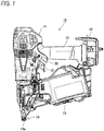
FIG. 1 is a right side view of a driving tool provided with an air duster structure. -
FIG. 2 is a left side view of the driving tool provided with the air duster structure. -
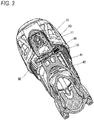
FIG. 3 is an A-A cross-sectional view of the driving tool. -
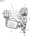
FIG. 4 is a left side view of the driving tool from which a tip cover member and a side cover member are detached. -
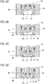
FIG. 5A is a perspective view of the tip cover member viewed from the reverse side, andFIG. 5B is a perspective view of the tip cover member viewed from the obverse side. -
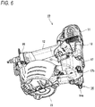
FIG. 6 is a perspective view of the driving tool viewed from below. -
FIG. 7 is a cross-sectional view of a flow amount adjustment mechanism according to a first embodiment, and a view of a condition where an operation portion is not operated. -
FIG. 8 is a cross-sectional view of the flow amount adjustment mechanism according to the first embodiment, and a view of a condition where the operation portion is depressed all the way in. -
FIGS. 9A to 9D are views explaining the operation of the flow amount adjustment mechanism according to the first embodiment,FIG. 9A is a view of the condition where the operation portion is not operated,FIG. 9B is a view of a condition where the operation portion is operated approximately 1/3 the way,FIG. 9C is a view of a condition where the operation portion is operated approximately 2/3 the way, andFIG. 9D is a view of a condition where the operation portion is fully operated. -
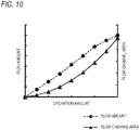
FIG. 10 is a graph showing a relationship between the operation amount, and the flow amount and the flow channel area according to the first embodiment. -
FIG. 11 is a cross-sectional view of a flow amount adjustment mechanism according to a second embodiment, and a view of a condition where the operation portion is not operated. -
FIG. 12 is a cross-sectional view of the flow amount adjustment mechanism according to the second embodiment, and a view of a condition where the operation portion is depressed all the way in. -
FIGS. 13A to 13E are views explaining the operation of the flow amount adjustment mechanism according to the second embodiment,FIG. 13A is a view of the condition where the operation portion is not operated,FIG. 13B is a view of a condition where the operation portion is operated approximately 1/4 the way,FIG. 13C is a view of a condition where the operation portion is operated approximately 2/4 the way,FIG. 13D is a view of a condition where the operation portion is operated approximately 3/4 the way, andFIG. 13E is a view of a condition where the operation portion is fully operated. -
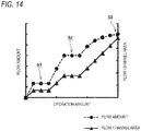
FIG. 14 is a graph showing a relationship between the operation amount, and the flow amount and the flow channel area according to the second embodiment. -
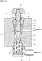
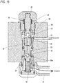
FIG. 15 is a cross-sectional view of a flow amount adjustment mechanism according to a third embodiment, and a view of a condition where the operation portion is not operated. -
FIG. 16 is a cross-sectional view of the flow amount adjustment mechanism according to the third embodiment, and a view of a condition where the operation portion is depressed all the way in. -
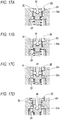
FIGS. 17A to 17D are views explaining the operation of the flow amount adjustment mechanism according to the third embodiment,FIG. 17A is a view of the condition where the operation portion is not operated,FIG. 17B is a view of a condition where the operation portion is operated approximately 1/3 the way,FIG. 17C is a view of a condition where the operation portion is operated approximately 2/3 the way, andFIG. 17D is a view of a condition where the operation portion is fully operated. -
FIGS. 18A and 18B are views explaining a stepwise adjustment of the flow channel area according to the third embodiment,FIG. 18A is a view of a condition where the flow amount of the air is controlled by the change of the clearance amount at a throttle portion, andFIG. 18B is a view of the condition where the flow amount of the air is controlled by the change of the opening amount of the opening portion. -
FIG. 19 is a graph showing a relationship between the operation amount, and the flow amount and the flow channel area according to the third embodiment. -
FIG. 20 is a graph showing the relationship between the operation amount, and the flow amount and the flow channel area when a release valve or a pipe line is formed in a simple tapered shape. - Hereinafter, embodiments of the present invention will be described with reference to the drawings. While in the following embodiments, as a usage example of the air duster structure, a
driving tool 10 provided with an air duster structure is cited as an example, the present invention is not limited thereto; the air duster structure according to the present invention may be applied to different tools. For example, the air duster structure according to the present embodiments may be applied to an air duster gun. - A first embodiment of the present invention will be described with reference to
FIGS. 1 to 10 . - The
driving tool 10 according to the present embodiment ejects a fastener by using externally supplied compressed air, and is provided with an air duster structure that jets air out of anozzle 17b by using this externally supplied compressed air. By thus providing thedriving tool 10 with the air duster structure, driving by the fastener and cleaning by the air duster can be performed without exchanging tools. - As shown in
FIG. 1 , thisdriving tool 10 is provided with atool body 11 having a striking mechanism inside, agrip 12 provided so as to protrude from thetool body 11 in an orthogonal direction, atrigger 13 provided on thegrip 12 so as to be operable, anose portion 14 provided so as to protrude on the tip of thetool body 11, amagazine 15 connected in the rear of thenose portion 14, and anoperation portion 30 provided so as to be depressable in order to actuate the air duster structure. - The striking mechanism incorporated in the
tool body 11 actuates a driver (which is a fastener driving member) by using the force of the compressed air. The driver is movable in the direction toward thenose portion 14 in order to eject a fastener. The driver having moved in the driving direction ejects a fastener that is set inside thenose portion 14. The fastener ejected by the driver is ejected from anejection hole 14a that is open at the tip of thenose portion 14. - When this
driving tool 10 is used, thegrip 12 is gripped and grasped, and thetrigger 13 is pulled. By this operation, the above-described striking mechanism is actuated to eject a fastener. - In the
magazine 15, a connection fastener is accommodated, and the foremost fasteners of this connection fastener are successively supplied in the direction toward the nose portion 14 (immediately below the driver before the driving operation) . - The compressed air for actuating the above-described striking mechanism and air duster structure is supplied from an air supply source such as an air compressor. Specifically, an air hose for supplying air connected to a compressor or the like is connected to an
end cap portion 16 provided on the rear end of thegrip 12, and the compressed air is supplied through this air hose. The compressed air supplied from theend cap portion 16 passes through an air supply channel formed inside thegrip 12, and is supplied to the striking mechanism or to the air duster structure. - In the striking mechanism, when the
trigger 13 is operated, the compressed air is supplied into a striking cylinder, this compressed air acts on a striking piston to drive the striking piston, and the driver coupled to the striking piston drives a nail. - In the air duster structure, when the
operation portion 30 is operated, the compressed air is jetted out of thenozzle 17b that is open in the neighborhood of thenose portion 14. As shown inFIG. 1 , theoperation portion 30 according to the present embodiment is disposed in a position where it can be operated with the hand grasping thegrip 12 when the worker grasps thegrip 12. Specifically, it is disposed in a position where it can be operated with the thumb of the right hand when thegrip 12 is gripped with the right hand. - As shown in
FIGS. 3 and4 , the above-described air duster structure is provided with a flow amount adjustment mechanism provided inside the housing of thetool body 11. On the downstream side of this flow amount adjustment mechanism, anair outlet 40 for taking out air to the outside of the housing is provided. To thisair outlet 40, aduster pipe arrangement 42 extending in a direction toward the tip of the tool body 11 (that is, a direction toward the nose portion 14) is connected. More specifically, theduster pipe arrangement 42 is connected through ajoint part 41 rotatably provided between it and theair outlet 40. - The
air outlet 40 is disposed on a side surface of thetool body 11 on the side opposite to theoperation portion 30. While theduster pipe arrangement 42 and thejoint part 41 connected to theair outlet 40 are disposed outside the housing of thetool body 11, as shown inFIG. 2 , they are covered with atip cover member 17 covering the tip of thetool body 11 and aside cover member 18 disposed in a position covering theair outlet 40. - On the reverse side of the
tip cover member 17, as shown inFIG. 5A , a pipearrangement holding portion 17a holding atip portion 42a of theduster pipe arrangement 42 is provided, and by this, thetip portion 42a of theduster pipe arrangement 42 is fixed by thetip cover member 17. Theduster pipe arrangement 42 is easily assembled to the pipearrangement holding portion 17a since it is a flexible tube made of a resin or the like and elastically deformable. - On the obverse side of the
tip cover member 17, as shown inFIGS. 5B and6 , theair nozzle 17b is open. Thisair nozzle 17b communicates with the above-described pipearrangement holding portion 17a. By this provision, on thetip cover member 17, of theair nozzle 17b communicating with theduster pipe arrangement 42, air is jetted out of thisnozzle 17b when theoperation portion 30 is operated. - The flow amount adjustment mechanism is for adjusting the amount of air jetted out of the
nozzle 17b, and as shown inFIG. 7 , is provided with a pipeline formation portion 20 forming apipe line 23 for circulating air, avalve member 31 disposed within thepipe line 23 and movable, theoperation portion 30 disposed on the tip of thevalve member 31 so as to be operable, and a valvemember pushing member 36 that pushes thevalve member 31 in the protruding direction. Into this flow amount adjustment mechanism, the compressed air can be introduced from the upstream side, and when the air supply source such as an air compressor and thetool body 11 are connected together, the compressed air is supplied to the upstream side at all times. On the downstream side of this flow amount adjustment mechanism, theair outlet 40 to which the duster pipe arrangement 42 (the joint part 41) is connectable is open. - The pipe
line formation portion 20 has a hollow portion forming thepipe line 23, and as shown inFIG. 8 , is structured so as to take the compressed air into thepipe line 23 through anupstream opening portion 21 that is open toward the upstream side. On the downstream side of theupstream opening portion 21, athrottle portion 23a is provided that controls the flow amount of the air in thepipe line 23 by gradually changing the amount of clearance between thepipe line 23 and thevalve member 31 when thevalve member 31 moves. Thisthrottle portion 23a is formed, as shown inFIGS. 7 and8 , in a tapered shape (a trumpet shape) such that the width of the opening (the diameter of the cross section) increases at an accelerated rate toward the movement direction of thevalve member 31, and is structured so that when thevalve member 31 moves in a direction that opens thepipe line 23, the amount of clearance is increased at an accelerated rate. - To "increase at an accelerated rate" referred to here means not that the flow channel area increases proportionally to the movement amount of the
valve member 31 when thevalve member 31 moves in the opening direction but that the flow channel area increases more rapidly than proportionally. - The "amount of clearance" referred to here means the length of the gap between the
pipe line 23 and thevalve member 31. - The
valve member 31 is structured so as to slide along with the depression of theoperation portion 30. While thevalve member 31 is pushed in the protruding direction by the valvemember pushing member 36 under natural conditions, when theoperation portion 30 is depressed against the pushing force of the valvemember pushing member 36, thevalve member 31 moves in the direction that opens thepipe line 23. In the present embodiment, atip sealing member 32 formed of an O ring or the like is attached to the tip of thevalve member 31, and under natural conditions, thepipe line 23 is closed by thistip sealing member 32 abutting on thethrottle portion 23a. When thevalve member 31 moves in the direction that opens thepipe line 23, a clearance occurs between thetip sealing member 32 and thethrottle portion 23a, and by this clearance, the flow amount of the air in thepipe line 23 is controlled. Then, when thevalve member 31 opens thepipe line 23, air is released from theair outlet 40, and air is jetted out of thenozzle 17b. In the present embodiment, it is unnecessary to dispose theduster pipe arrangement 42 inside the housing since thevalve member 31 and theair outlet 40 are disposed in the pushing direction of theoperation portion 30 and theair outlet 40 is formed on the side opposite to theoperation portion 30. - According to this structure, since the flow channel area of the
throttle portion 23a rapidly increases as the operation amount of theoperation portion 30 increases, even if the difference in pressure between in front of and behind thethrottle portion 23a becomes small by operating theoperation portion 30 to a certain extent, the decrease in the flow amount because of the decrease in the pressure difference can be compensated by the increase in the flow channel area, so that the relationship between the operation amount of theoperation portion 30 and the amount of air jetted out of thenozzle 17b can be made close to a proportional relationship. - That is, when the
throttle portion 23a is formed not in the trumpet shape but in a simple tapered shape (conical surface), as shown inFIG. 20 , as the flow amount of the air increases, the pressure in the accumulator provided on the upstream side of the release valve decreases and the pressure difference between in front of and behind the throttle of the release valve becomes small, so that the change in the flow amount with respect to the change in the operation amount becomes small. For this reason, after theoperation portion 30 is operated to a certain extent, the amount of air jetted out of thenozzle 17b does not largely change even if theoperation portion 30 is operated any further and this deteriorates operability. - In this regard, according to the present embodiment, as shown in
FIGS. 9A to 9D , since operation amounts M1 to M3 of theoperation portion 30 are not proportional to the clearance amounts G1 to G3, it is possible to make the flow channel area very small at the start of the operation of theoperation portion 30 and make the flow channel area very large at the end of the operation of theoperation portion 30. Specifically, when theoperation portion 30 is operated by the predetermined operation amount M1 from an initial position BL of thevalve member 31 where the flow channel is closed (seeFIG. 9A ), the clearance amount is G1 (seeFIG. 9B ). When theoperation portion 30 is operated by twice the predetermined operation amount M1 (M2) from the initial position BL of thevalve member 31, the clearance amount is G2 (seeFIG. 9C ). When theoperation portion 30 is operated by three times the predetermined operation amount M1 (M3) from the initial position BL of thevalve member 31, the clearance amount is G3 (seeFIG. 9C ). In the case of a simple tapered shape (a conical surface), G2 should be twice G1, and G3 should be three times G1; however, in the present embodiment, since the clearance amount increases at an accelerated rate with respect to the operation amount of theoperation portion 30, G2 is not less than twice G1, and G3 is not less than three times G1. As described above, the present embodiment is purposefully structured so that the flow channel area largely increases extremely toward the rear. Therefore, even when the pressure difference between in front of and behind thethrottle portion 23a becomes small by operating theoperation portion 30 to a certain extent and the pressure to jet out the air decreases, the decrease in the pressure can be compensated by the increase in the flow channel area, so that as shown inFIG. 10 , the relationship between the operation amount of theoperation portion 30 and the amount of air jetted out of thenozzle 17b can be made close to a proportional relationship. - A second embodiment of the present invention will be described with reference to
FIGS. 11 to 14 . Since the present invention is different from the first embodiment only in the structure of the flow amount adjustment mechanism, overlapping descriptions are avoided and only the flow amount adjustment mechanism will be described. - The flow amount adjustment mechanism according to the present embodiment is for adjusting the amount of air jetted out of the
nozzle 17b, and as shown inFIG. 11 , is provided with the pipeline formation portion 20 forming thepipe line 23 for circulating air, thevalve member 31 disposed within thepipe line 23 and movable, theoperation portion 30 disposed on the tip of thevalve member 31 so as to be operable, and the valvemember pushing member 36 that pushes thevalve member 31 in the protruding direction. Into this flow amount adjustment mechanism, the compressed air can be introduced from the upstream side, and when the air supply source such as an air compressor is connected to thetool body 11, the compressed air is supplied to the upstream side at all times. On the downstream side of this flow amount adjustment mechanism, theair outlet 40 to which the duster pipe arrangement 42 (the joint part 41) is connectable is open. - The pipe
line formation portion 20 has a hollow portion forming thepipe line 23, and as shown inFIG. 12 , is structured so as to take the compressed air into thepipe line 23 through theupstream opening portion 21 that is open toward the upstream side. On the downstream side of theupstream opening portion 21, thethrottle portion 23a is provided that controls the flow amount of the air in thepipe line 23 by gradually changing the amount of clearance between thepipe line 23 and thevalve member 31 when thevalve member 31 moves. Thisthrottle portion 23a is formed, as shown inFIGS. 11 and12 , in a stepped shape where tapered portions and cylindrical portions are alternately arranged. Specifically, the following are provided: a first taperedportion 23c expanding toward the downstream side; a firstparallel portion 23f formed in substantially the same diameter as the maximum diameter of the first taperedportion 23c so as to be continuous with the first taperedportion 23c; a second taperedportion 23d expanding toward the downstream side so as to be continuous with the firstparallel portion 23f; a secondparallel portion 23g formed in substantially the same diameter as the maximum diameter of the second taperedportion 23d so as to be continuous with the second taperedportion 23d; a thirdtapered portion 23e expanding toward the downstream side so as to be continuous with the secondparallel portion 23g; and a thirdparallel portion 23h formed in substantially the same diameter as the maximum diameter of the thirdtapered portion 23e so as to be continuous with the thirdtapered portion 23e. This embodiment is merely an example and the number of steps of the stepped shape may be changed as appropriate. - The
valve member 31 is structured so as to slide along with the depression of theoperation portion 30. While thevalve member 31 is pushed in the protruding direction by the valvemember pushing member 36 under natural conditions, when theoperation portion 30 is depressed against the pushing force of the valvemember pushing member 36, thevalve member 31 moves in the direction that opens thepipe line 23. In the present embodiment, thetip sealing member 32 formed of an O ring or the like is attached to the tip of thevalve member 31, and under natural conditions, thepipe line 23 is closed by thistip sealing member 32 abutting on thethrottle portion 23a. When thevalve member 31 moves in the direction that opens thepipe line 23, a clearance occurs between thetip sealing member 32 and thethrottle portion 23a, and by this clearance, the flow amount of the air in thepipe line 23 is controlled. Then, when thevalve member 31 opens thepipe line 23, air is released from theair outlet 40, and air is jetted out of thenozzle 17b. In the present embodiment, it is unnecessary to dispose theduster pipe arrangement 42 inside the housing since thevalve member 31 and theair outlet 40 are disposed in the pushing direction of theoperation portion 30. - According to this structure, since the flow channel area can be stepwisely adjusted by the stepped shape, even when the pressure difference between in front of and behind the
throttle portion 23a becomes small by operating theoperation portion 30 to a certain extent and the pressure to jet out the air decreases, the decrease in the pressure can be compensated by the increase in the flow channel area, so that the relationship between the operation amount of theoperation portion 30 and the amount of air jetted out of thenozzle 17b can be made close to a proportional relationship. - That is, according to the present embodiment, as shown in
FIG. 13B , when thetip sealing member 32 is moving in a position facing a tapered portion, the amount of clearance between thetip sealing member 32 and thethrottle portion 23a increases little by little, whereas as shown inFIGS. 13C, 13D and 13E , when thetip sealing member 32 faces a parallel portion, the amount of clearance between thetip sealing member 32 and thethrottle portion 23a does not change. For this reason, by adjusting the intervals and the diameters of the tapered portions and the parallel portions, the relationship between the operation amount of theoperation portion 30 and the flow channel area can be easily set and changed. For this reason, even when the pressure difference between in front of and behind thethrottle portion 23a becomes small by operating theoperation portion 30 to a certain extent and the pressure to jet out the air decreases, the decrease in the pressure can be compensated by the increase in the flow channel area, so that as shown inFIG. 14 , the relationship between the operation amount of theoperation portion 30 and the amount of air jetted out of thenozzle 17b can be made close to a proportional relationship. - Moreover, by stepwisely adjusting the flow channel area, it is made easy to keep constant the amount of air jetted out of the
nozzle 17b. For example, as shown inFIG. 13C , in a range where thetip sealing member 32 faces the firstparallel portion 23f, as shown at S1 inFIG. 14 , even if the operation amount of theoperation portion 30 changes in some degree, the amount of air jetted out of thenozzle 17b is kept substantially constant. Likewise, as shown inFIG. 13D , in a range where thetip sealing member 32 faces the secondparallel portion 23g, as shown at S2 inFIG. 14 , even if the operation amount of theoperation portion 30 changes in some degree, the amount of air jetted out of thenozzle 17b is kept substantially constant. Moreover, as shown inFIG. 13E , when thetip sealing member 32 is operated to a position where thetip sealing member 32 faces the thirdparallel portion 23h (to the bottom dead point), as shown at S3 inFIG. 14 , the amount of air jetted out of thenozzle 17b is stabilized. - As described above, by making it possible to keep substantially constant the amount of air jetted out of the
nozzle 17b even if the operation amount of theoperation portion 30 changes in some degree, the amount of air jetted out of thenozzle 17b can be kept constant without the user continuing to apply a constant force to theoperation portion 30. For example, even in a situation where it is difficult to continue applying a constant force to theoperation portion 30 such as a situation where the user uses the machine while shaking thenozzle 17b under a condition where he/she is holding the machine, the amount of air jetted out of thenozzle 17b can be kept constant. - A third embodiment of the present invention will be described with reference to
FIGS. 15 to 19 . Since the present embodiment is different from the first embodiment only in the structure of the flow amount adjustment mechanism, overlapping descriptions are avoided and only the flow amount adjustment mechanism will be described. - The flow amount adjustment mechanism according to the present embodiment is for adjusting the amount of air jetted out of the
nozzle 17b, and as shown inFIG. 15 , is provided with the pipeline formation portion 20 forming thepipe line 23 for circulating air, thevalve member 31 disposed within thepipe line 23 and movable, theoperation portion 30 disposed on the tip of thevalve member 31 so as to be operable, the valvemember pushing member 36 that pushes thevalve member 31 in the protruding direction, and a sealingmember 37 that abuts thevalve member 31 to seal the air. Into this flow amount adjustment mechanism, the compressed air can be introduced from the upstream side, and when the air supply source such as an air compressor is connected, the compressed air is supplied to the upstream side at all times. On the downstream side of this flow amount adjustment mechanism, theair outlet 40 to which the duster pipe arrangement 42 (the joint part 41) is connectable is open. - The pipe
line formation portion 20 has a hollow portion forming thepipe line 23, and in the present embodiment, part of the housing of thetool body 11 is made the pipeline formation portion 20. That is, in the housing of thetool body 11, a through hole that passes through in a direction orthogonal to the driving direction of the fastener is formed, and thepipe line 23 is formed of this through hole. This pipeline formation portion 20 is structured, as shown inFIG. 16 , so as to take in the compressed air into thepipe line 23 from theupstream opening portion 21 that is open toward the upstream side. This pipeline formation portion 20 is provided with a blockingportion 23i capable of adjusting the opening amount of anopening portion 35 described later. The blockingportion 23i has a cylinder inner surface shape facing the outer peripheral surface of thevalve member 31. - The
valve member 31 is structured so as to slide along with the depression of theoperation portion 30. While thevalve member 31 is pushed in the protruding direction by the valvemember pushing member 36 under natural conditions, when theoperation portion 30 is depressed against the pushing force of the valvemember pushing member 36, thevalve member 31 moves in the direction that opens thepipe line 23. - This
valve member 31 is hollow and provided with aninner pipe line 34 through which air can pass. On the upstream side of theinner pipe line 34, anintake 33 for taking in the compressed air is provided, and on the downstream side of theinner pipe line 34, the openingportion 35 for discharging the compressed air toward theair outlet 40 is provided. The compressed air supplied from the air supply source flows into theinner pipe line 34 from theintake 33, and passes through the openingportion 35 to flow in a direction toward theair outlet 40. The openingportion 35 is open in a direction orthogonal to the movement direction of thevalve member 31, and can face the blockingportion 23i of the pipeline formation portion 20. Specifically, this openingportion 35 is provided, as shown inFIGS. 17A to 17D , continuously with thethrottle portion 23a described later, and after thevalve member 31 moves and thethrottle portion 23a passes the blockingportion 23i, the openingportion 35 faces the blockingportion 23i. - On the downstream side of this opening
portion 35, thethrottle portion 23a is provided that controls the flow amount of the air in thepipe line 23 by gradually changing the amount of clearance between thepipe line 23 and thevalve member 31 when thevalve member 31 moves. While thethrottle portion 23a is formed by tapering the outer peripheral surface of thevalve member 31 in the present embodiment, the present invention is not limited thereto; thethrottle portion 23a may be formed by tapering the inner peripheral surface of thepipe line 23 or a stepped shape may be used instead of the tapered shape. - In the present embodiment, the sealing
member 37 formed of an O ring or the like is fixed to the housing side of thetool body 11. Under natural conditions, as shown inFIG. 15 , this sealingmember 37 abuts on the outer peripheral surface (a sealing surface 38) of thevalve member 31 to seal so that no air flows into theintake 33. When thevalve member 31 moves in the direction that opens thepipe line 23, the sealing state of the sealingmember 37 and the sealingsurface 38 is released, so that air is supplied from theintake 33 to theinner pipe line 34. The flow amount of the air supplied to theinner pipe line 34 is controlled by the change in the clearance amount at thethrottle portion 23a and the change in the opening amount of the openingportion 35. The air having its flow amount controlled is released from theair outlet 40 and jetted out of thenozzle 17b. In the present embodiment, it is unnecessary to dispose theduster pipe arrangement 42 inside the housing since thevalve member 31 and theair outlet 40 are disposed in the pushing direction of theoperation portion 30 and theair outlet 40 is formed on the side opposite to theoperation portion 30. - According to this structure, since the flow channel area can be stepwisely adjusted by the flow amount adjustment at two places, even when the pressure difference between in front of and behind the
throttle portion 23a becomes small by operating theoperation portion 30 to a certain extent and the pressure to jet out the air decreases, the decrease in the pressure can be compensated by the increase in the flow channel area, so that the relationship between the operation amount of theoperation portion 30 and the amount of air jetted out of thenozzle 17b can be made close to a proportional relationship. - That is, according to the present embodiment, as shown in
FIGS. 17A to 17C , since the openingportion 35 is blocked until theoperation portion 30 is operated and moves to a predetermined position, the flow amount adjustment is performed only by thethrottle portion 23a. At this stage, as shown inFIG. 18A , the flow amount of the air is controlled by the change in the amount of clearance between thethrottle portion 23a and the blockingportion 23i. Then, as shown inFIG. 17D , when theoperation portion 30 is further operated and moves to the predetermined position, part of the openingportion 35 moves to the downstream side of the blockingportion 23i, so that the air flows directly to the downstream side from the openingportion 35. At this stage, the flow amount adjustment by thethrottle portion 23a is not performed, and as shown inFIG. 18B , the flow amount of the air is controlled by the change in the opening amount of the openingportion 35. - According to this structure, the flow amount of the air can be increased as a stretch when the
operation portion 30 is operated to a certain extent. For this reason, even when the pressure difference between in front of and behind thethrottle portion 23a becomes small by operating theoperation portion 30 to a certain extent and the pressure to jet out the air decreases, the decrease in the pressure can be compensated by the increase in the flow channel area, so that as shown inFIG. 19 , the relationship between the operation amount of theoperation portion 30 and the amount of air jetted out of thenozzle 17b can be made close to a proportional relationship. - While in the above-described embodiment, the flow amount of the air in the
pipe line 23 is controlled by the change in the clearance amount at thethrottle portion 23a and the change in the opening amount of the openingportion 35, the method of adjusting the flow channel area by the flow amount adjustment at two places is not limited thereto. That is, at least two throttle portions where the flow channel area change amounts with respect to the movement amount of thevalve member 31 are different may be provided. For example, a throttle portion where the change in the flow channel area is small and a throttle portion where the change is large may be combined. Specifically, by providing two or more tapered throttle portions as described in the first embodiment and making the angles of the tapered surfaces of the throttle portions different from each other, the flow channel area change amounts with respect to the movement amount of thevalve member 31 can be made different from each other. - In the above-described embodiment, the opening
portion 35 is provided on thevalve member 31, and the blockingportion 23i is provided on the pipe line formation portion 20 (the pipe line 23). However, the openingportion 35 may be provided on the pipe line formation portion 20 (the pipe line 23), and the blockingportion 23i may be provided on thevalve member 31. - According to an aspect of the invention, there is provided an air duster structure that is configured to jet compressed air out of a nozzle, the air duster structure comprising: a flow amount adjustment mechanism which is configured to adjust an amount of air jetted out of the nozzle, wherein the flow amount adjustment mechanism includes: a pipe line for circulating air; a valve member disposed inside the pipe line and being movable; and a throttle portion configured to gradually change an area of a flow channel in which air circulates, with a movement of the valve member, to control a flow amount of the air in the pipe line, and the throttle portion is structured so as to increase the area of the flow channel at an accelerated rate when the valve member moves in a direction that opens the pipe line.
- In the above described structure, the throttle portion is structured so as to increase the area of the flow channel at an accelerated rate when the valve member moves in the direction that opens the pipe line. According to the structure, as the operation amount increases, the flow channel area of the throttle portion increases at an accelerated rate. Therefore, even when the pressure difference between in front of and behind the throttle portion becomes small by operating the operation portion to a certain extent and the pressure in an accumulator decreases, the decrease in the pressure can be compensated by the increase in the flow channel area, so that the relationship between the operation amount of the operation portion and the amount of air jetted out of the nozzle can be made close to a proportional relationship.
- According to an aspect of the invention, there is provided an air duster structure that is configured to jet compressed air out of a nozzle, the air duster structure comprising: a flow amount adjustment mechanism which is configured to adjust an amount of air jetted out of the nozzle, wherein the flow amount adjustment mechanism includes: a pipe line for circulating air; a valve member disposed inside the pipe line and being movable; and a throttle portion configured to gradually change an area of a flow channel in which air circulates, with a movement of the valve member, to control a flow amount of the air in the pipe line, and the throttle portion has a stepped shape where the area of the flow channel is stepwisely changed when the valve member moves.
- In the above described structure, the throttle portion has the stepped shape where the area of the flow channel is stepwisely changed when the valve member moves. According to the structure, the flow channel area can be stepwisely adjusted by the stepped shape. Therefore, even when the pressure difference between in front of and behind the throttle portion becomes small by operating the operation portion to a certain extent and the pressure to jet out the air decreases, the decrease in the pressure can be compensated by the increase in the flow channel area, so that the relationship between the operation amount of the operation portion and the amount of air jetted out of the nozzle can be made close to a proportional relationship.
- By stepwisely adjusting the flow channel area, it is made easy to keep constant the amount of air jetted out of the nozzle. That is, if the release valve or the pipe line is formed in the tapered shape and the amount of air is adjusted, the operation amount of the operation portion directly affects the amount of air being jetted out, so that in order to keep constant the amount of air jetted out of the nozzle, it is necessary that the operation amount of the operation portion be also kept constant. For this reason, it is difficult to keep constant the amount of air jetted out of the nozzle in a situation where it is difficult for the user to continue applying a constant force to the operation portion (for example, in a situation where the user uses the machine while shaking the nozzle under a condition where he/she is holding the machine). In this regard, according to the present invention, since the amount of air jetted out of the nozzle can be kept substantially constant even if the operation amount of the operation portion changes in some degree, the amount of air jetted out of the nozzle can be kept constant without the user continuing to apply a constant force to the operation portion.
- According to an aspect of the invention, there is provided an air duster structure that is configured to jet compressed air out of a nozzle, the air duster structure comprising: a flow amount adjustment mechanism which is configured to adjust an amount of air jetted out of the nozzle, wherein the flow amount adjustment mechanism includes: a pipe line for circulating air; a valve member disposed inside the pipe line and being movable; and at least two throttle portions configured to gradually change areas of flow channels in which air circulates, with a movement of the valve member, to control a flow amount of the air in the pipe line, and change amounts of the areas of the flow channels of the throttle portions with respect to a movement amount of the valve member are different from each other.
- In the above described structure, at least two throttle portions are provided where the flow channel area change amounts with respect to the movement amount of the valve member can be made different from each other. According to the structure, the flow channel area can be stepwisely adjusted by the flow amount adjustment at two places. Therefore, even when the pressure difference between in front of and behind the throttle portion becomes small by operating the operation portion to a certain extent and the pressure to jet out the air decreases, the decrease in the pressure can be compensated by the increase in the flow channel area, so that the relationship between the operation amount of the operation portion and the amount of air jetted out of the nozzle can be made close to a proportional relationship.
- The throttle portion may be configured to gradually change an amount of clearance between the pipe line and the valve member when the valve member moves, to control the flow amount of the air in the pipe line. In this case, the flow channel area can be changed by the change of the clearance amount.
- According to an aspect of the invention, there is provided an air duster structure that is configured to jet compressed air out of a nozzle, the air duster structure comprising: a flow amount adjustment mechanism which is configured to adjust an amount of air jetted out of the nozzle, wherein the flow amount adjustment mechanism includes: a pipe line for circulating air; a valve member disposed inside the pipe line and being movable; and a throttle portion configured to gradually change an amount of clearance between the pipe line and the valve member when the valve member moves, an opening portion that is open in a direction orthogonal to a direction in which the valve member moves is provided on one of the pipe line or the valve member, a blocking portion capable of adjusting an opening amount of the opening portion is provided on the other of the pipe line or the valve member, and the flow amount adjustment mechanism is configured to control a flow amount of the air in the pipe line by a change of the clearance amount at the throttle portion and a change of the opening amount of the opening portion.
- In the above described structure, the flow amount of the air in the pipe line is controlled by the change of the clearance amount at the throttle portion and the change of the opening amount of the opening portion. According to the structure, the flow channel area can be stepwisely adjusted by the flow amount adjustment at two places. Therefore, even when the pressure difference between in front of and behind the throttle portion becomes small by operating the operation portion to a certain extent and the pressure to jet out the air decreases, the decrease in the pressure can be compensated by the increase in the flow channel area, so that the relationship between the operation amount of the operation portion and the amount of air jetted out of the nozzle can be made close to a proportional relationship.
- According to an aspect of the invention, there is also provided a driving tool comprising the air duster structure, the driving tool configured to eject a fastener by using the compressed air.
- According to an aspect of the invention, there is also provided a driving tool which includes an air duster structure that is configured to jet compressed air out of a nozzle, and which is configured to eject a fastener by using the compressed air, the driving tool comprising: an operation portion; a pipe line for circulating air; and a valve member which is configured to move in the pipe line with an operation to the operation portion, wherein, when the operation portion is operated, the compressed air is jetted out of the nozzle, and, when the operation portion is operated, the valve member moves in the pipe line, and an area of a flow channel in which air circulates is changed with the movement of the valve member so that a flow amount of the air in the pipe line is adjusted.
Claims (8)
- A driving tool which includes an air duster structure that is configured to jet compressed air out of a nozzle, and which is configured to eject a fastener by using the compressed air, the driving tool comprising:an operation portion;a pipe line for circulating air; anda valve member which is configured to move in the pipe line with an operation to the operation portion, wherein,when the operation portion is operated, the compressed air is jetted out of the nozzle, and,when the operation portion is operated, the valve member moves in the pipe line, and an area of a flow channel in which air circulates is changed with the movement of the valve member so that a flow amount of the air in the pipe line is adjusted.
- The driving tool according to claim 1, further comprising:a throttle portion configured to gradually change the area of the flow channel, with the movement of the valve member, to control the flow amount of the air in the pipe line, the throttle portion structured so as to increase the area of the flow channel at an accelerated rate when the valve member moves in a direction that opens the pipe line.
- The driving tool according to claim 1 or 2, wherein
the throttle portion includes at least two throttle portions configured to gradually change areas of flow channels in which air circulates, with the movement of the valve member, to control the flow amount of the air in the pipe line, and
change amounts of the areas of the flow channels of the throttle portions with respect to the movement amount of the valve member are different from each other. - The driving tool according to any one of claims 1 to 3, wherein
the throttle portion is configured to gradually change an amount of clearance between the pipe line and the valve member when the valve member moves, to control the flow amount of the air in the pipe line. - The driving tool according to claim 4, wherein
an opening portion that is open in a direction orthogonal to a direction in which the valve member moves is provided on one of the pipe line or the valve member,
a blocking portion capable of adjusting an opening amount of the opening portion is provided on the other of the pipe line or the valve member, and
the flow amount of the air in the pipe line is controlled by a change of the amount of the clearance at the throttle portion and a change of the opening amount of the opening portion. - The driving tool according to any one of claims 1 to 5, wherein
the throttle portion has a stepped shape where the area of the flow channel is stepwisely changed when the valve member moves. - The driving tool according to claim 3, wherein
the at least two throttle portions include: a first throttle configured to adjust the flow amount of the air in the pipe line when an operation amount of the operation portion is within a predetermined amount; and a second throttle configured to adjust the flow amount of the air in the pipe line when the operation amount of the operation portion exceeds the predetermined amount. - The driving tool according to claim 7, wherein
the first throttle is disposed downstream side of the second throttle in the pipe line.
Priority Applications (3)
| Application Number | Priority Date | Filing Date | Title |
|---|---|---|---|
| EP19166133.9A EP3549721B1 (en) | 2016-12-28 | 2017-12-22 | Air duster structure and driving tool |
| DK19166133.9T DK3549721T3 (en) | 2016-12-28 | 2017-12-22 | Dust blower structure and recovery tool |
| EP20201940.2A EP3800011B1 (en) | 2016-12-28 | 2017-12-22 | Air duster structure and driving tool |
Applications Claiming Priority (1)
| Application Number | Priority Date | Filing Date | Title |
|---|---|---|---|
| JP2016256590A JP6780499B2 (en) | 2016-12-28 | 2016-12-28 | Air duster structure and driving tool |
Related Child Applications (3)
| Application Number | Title | Priority Date | Filing Date |
|---|---|---|---|
| EP19166133.9A Division-Into EP3549721B1 (en) | 2016-12-28 | 2017-12-22 | Air duster structure and driving tool |
| EP19166133.9A Division EP3549721B1 (en) | 2016-12-28 | 2017-12-22 | Air duster structure and driving tool |
| EP20201940.2A Division EP3800011B1 (en) | 2016-12-28 | 2017-12-22 | Air duster structure and driving tool |
Publications (2)
| Publication Number | Publication Date |
|---|---|
| EP3348356A1 true EP3348356A1 (en) | 2018-07-18 |
| EP3348356B1 EP3348356B1 (en) | 2020-04-01 |
Family
ID=60811873
Family Applications (3)
| Application Number | Title | Priority Date | Filing Date |
|---|---|---|---|
| EP19166133.9A Active EP3549721B1 (en) | 2016-12-28 | 2017-12-22 | Air duster structure and driving tool |
| EP20201940.2A Active EP3800011B1 (en) | 2016-12-28 | 2017-12-22 | Air duster structure and driving tool |
| EP17210101.6A Active EP3348356B1 (en) | 2016-12-28 | 2017-12-22 | Air duster structure and driving tool |
Family Applications Before (2)
| Application Number | Title | Priority Date | Filing Date |
|---|---|---|---|
| EP19166133.9A Active EP3549721B1 (en) | 2016-12-28 | 2017-12-22 | Air duster structure and driving tool |
| EP20201940.2A Active EP3800011B1 (en) | 2016-12-28 | 2017-12-22 | Air duster structure and driving tool |
Country Status (6)
| Country | Link |
|---|---|
| US (2) | US10981266B2 (en) |
| EP (3) | EP3549721B1 (en) |
| JP (1) | JP6780499B2 (en) |
| CN (1) | CN108339805B (en) |
| DK (3) | DK3800011T3 (en) |
| TW (2) | TW202237345A (en) |
Families Citing this family (1)
| Publication number | Priority date | Publication date | Assignee | Title |
|---|---|---|---|---|
| JP1705427S (en) * | 2021-07-09 | 2022-01-19 | Air duster body |
Citations (5)
| Publication number | Priority date | Publication date | Assignee | Title |
|---|---|---|---|---|
| JPH10109280A (en) | 1996-10-04 | 1998-04-28 | Hitachi Koki Co Ltd | Driving machine |
| EP1366863A2 (en) * | 2002-05-31 | 2003-12-03 | Hitachi Koki Co., Ltd. | Nail gun provided with duster function |
| US20080087704A1 (en) * | 2006-09-29 | 2008-04-17 | Wan-Fu Wen | Nail Gun with Air Injection Mechanism |
| US20080105729A1 (en) * | 2006-11-03 | 2008-05-08 | Basso Industry Corp. | Dust-removing structure of a nailer |
| EP2402121A2 (en) * | 2010-07-01 | 2012-01-04 | Stanley Fastening Systems L.P. | Fastener driving device with dust blower |
Family Cites Families (13)
| Publication number | Priority date | Publication date | Assignee | Title |
|---|---|---|---|---|
| FR1309839A (en) * | 1961-06-13 | 1962-11-23 | Bertin & Cie | Balanced valve, especially for hot gases |
| JPH07112674B2 (en) * | 1990-01-10 | 1995-12-06 | 株式会社マキタ | Head valve device for pneumatic nailer |
| CN2170420Y (en) * | 1993-08-05 | 1994-06-29 | 崔国彪 | Column-type throttle valve |
| JPH08145507A (en) * | 1994-11-24 | 1996-06-07 | Sanyo Electric Co Ltd | Refrigerant flow control valve and refrigerating equipment using refrigerant flow control valve |
| EP1128109A1 (en) * | 2000-02-22 | 2001-08-29 | Siemens Building Technologies AG | Valve for control device |
| CN2835725Y (en) * | 2005-07-14 | 2006-11-08 | 王战勇 | Step type oblique flapper valve |
| US7950557B2 (en) * | 2006-12-07 | 2011-05-31 | Max Co., Ltd. | Pneumatic tool with air duster |
| JP5115257B2 (en) | 2008-03-14 | 2013-01-09 | 日立工機株式会社 | Pneumatic tool |
| US7784560B2 (en) * | 2008-03-31 | 2010-08-31 | Illinois Tool Works Inc. | Cap assembly of a fastener-driving tool having switch mechanism incorporated therein for switching modes of operation of the fastener-driving tool |
| JP2008173767A (en) | 2008-04-03 | 2008-07-31 | Hitachi Koki Co Ltd | Air duster |
| JP5627965B2 (en) * | 2010-09-13 | 2014-11-19 | 株式会社マキタ | Pneumatic tool |
| CN103032580B (en) * | 2012-12-27 | 2014-11-05 | 吴忠中创自控阀有限公司 | Multi-stage throttling regulation valve |
| JP5716800B2 (en) | 2013-09-17 | 2015-05-13 | マックス株式会社 | Pneumatic tool with air duster |
-
2016
- 2016-12-28 JP JP2016256590A patent/JP6780499B2/en active Active
-
2017
- 2017-12-20 US US15/848,326 patent/US10981266B2/en active Active
- 2017-12-21 TW TW111123865A patent/TW202237345A/en unknown
- 2017-12-21 TW TW106145029A patent/TWI772345B/en active
- 2017-12-22 DK DK20201940.2T patent/DK3800011T3/en active
- 2017-12-22 EP EP19166133.9A patent/EP3549721B1/en active Active
- 2017-12-22 DK DK17210101.6T patent/DK3348356T3/en active
- 2017-12-22 EP EP20201940.2A patent/EP3800011B1/en active Active
- 2017-12-22 DK DK19166133.9T patent/DK3549721T3/en active
- 2017-12-22 EP EP17210101.6A patent/EP3348356B1/en active Active
- 2017-12-26 CN CN201711432199.5A patent/CN108339805B/en active Active
-
2021
- 2021-02-24 US US17/183,793 patent/US20210178560A1/en active Pending
Patent Citations (5)
| Publication number | Priority date | Publication date | Assignee | Title |
|---|---|---|---|---|
| JPH10109280A (en) | 1996-10-04 | 1998-04-28 | Hitachi Koki Co Ltd | Driving machine |
| EP1366863A2 (en) * | 2002-05-31 | 2003-12-03 | Hitachi Koki Co., Ltd. | Nail gun provided with duster function |
| US20080087704A1 (en) * | 2006-09-29 | 2008-04-17 | Wan-Fu Wen | Nail Gun with Air Injection Mechanism |
| US20080105729A1 (en) * | 2006-11-03 | 2008-05-08 | Basso Industry Corp. | Dust-removing structure of a nailer |
| EP2402121A2 (en) * | 2010-07-01 | 2012-01-04 | Stanley Fastening Systems L.P. | Fastener driving device with dust blower |
Also Published As
| Publication number | Publication date |
|---|---|
| TWI772345B (en) | 2022-08-01 |
| JP2018108615A (en) | 2018-07-12 |
| US10981266B2 (en) | 2021-04-20 |
| EP3348356B1 (en) | 2020-04-01 |
| EP3800011B1 (en) | 2022-03-30 |
| CN108339805A (en) | 2018-07-31 |
| EP3549721B1 (en) | 2020-11-25 |
| US20210178560A1 (en) | 2021-06-17 |
| TW202237345A (en) | 2022-10-01 |
| DK3348356T3 (en) | 2020-06-29 |
| EP3800011A1 (en) | 2021-04-07 |
| EP3549721A1 (en) | 2019-10-09 |
| DK3549721T3 (en) | 2020-12-07 |
| US20180178363A1 (en) | 2018-06-28 |
| JP6780499B2 (en) | 2020-11-04 |
| CN108339805B (en) | 2022-04-29 |
| DK3800011T3 (en) | 2022-04-25 |
| TW201836786A (en) | 2018-10-16 |
Similar Documents
| Publication | Publication Date | Title |
|---|---|---|
| TWI247651B (en) | Nail gun provided with duster function | |
| EP2667079B1 (en) | Auto/single functions selecting device for grease gun and method for operating the same | |
| US20210178560A1 (en) | Air duster structure and driving tool | |
| JP2008296354A (en) | Pneumatic tool | |
| JP6972550B2 (en) | Air duster structure | |
| JP7036162B2 (en) | Driving tool | |
| US20170361442A1 (en) | Feed Piston Pressure Tube | |
| US9205545B2 (en) | Auxiliary handle of pneumatic tool | |
| WO2016114338A1 (en) | Spray gun | |
| JP2020168721A5 (en) | ||
| JP6794828B2 (en) | Air duster structure and driving tool | |
| JP6870495B2 (en) | Pneumatic tool with air duster | |
| JP3203343U (en) | Shooting device that launches using air pressure | |
| JP6776894B2 (en) | On-off valve structure | |
| JP2016098884A (en) | Gas flow rate adjustment valve and spray gun including the gas flow rate adjustment valve | |
| US20230087047A1 (en) | Spray gun, in particular a pressurised air atomisation paint spray gun, in particular a hand-held pressurised air atomisation paint spray gun | |
| JP6870498B2 (en) | Pneumatic tool with air duster | |
| JP2017035673A (en) | Spray gun |
Legal Events
| Date | Code | Title | Description |
|---|---|---|---|
| PUAI | Public reference made under article 153(3) epc to a published international application that has entered the european phase |
Free format text: ORIGINAL CODE: 0009012 |
|
| STAA | Information on the status of an ep patent application or granted ep patent |
Free format text: STATUS: THE APPLICATION HAS BEEN PUBLISHED |
|
| AK | Designated contracting states |
Kind code of ref document: A1 Designated state(s): AL AT BE BG CH CY CZ DE DK EE ES FI FR GB GR HR HU IE IS IT LI LT LU LV MC MK MT NL NO PL PT RO RS SE SI SK SM TR |
|
| AX | Request for extension of the european patent |
Extension state: BA ME |
|
| STAA | Information on the status of an ep patent application or granted ep patent |
Free format text: STATUS: REQUEST FOR EXAMINATION WAS MADE |
|
| 17P | Request for examination filed |
Effective date: 20180724 |
|
| RBV | Designated contracting states (corrected) |
Designated state(s): AL AT BE BG CH CY CZ DE DK EE ES FI FR GB GR HR HU IE IS IT LI LT LU LV MC MK MT NL NO PL PT RO RS SE SI SK SM TR |
|
| GRAP | Despatch of communication of intention to grant a patent |
Free format text: ORIGINAL CODE: EPIDOSNIGR1 |
|
| STAA | Information on the status of an ep patent application or granted ep patent |
Free format text: STATUS: GRANT OF PATENT IS INTENDED |
|
| INTG | Intention to grant announced |
Effective date: 20191029 |
|
| GRAS | Grant fee paid |
Free format text: ORIGINAL CODE: EPIDOSNIGR3 |
|
| GRAA | (expected) grant |
Free format text: ORIGINAL CODE: 0009210 |
|
| STAA | Information on the status of an ep patent application or granted ep patent |
Free format text: STATUS: THE PATENT HAS BEEN GRANTED |
|
| AK | Designated contracting states |
Kind code of ref document: B1 Designated state(s): AL AT BE BG CH CY CZ DE DK EE ES FI FR GB GR HR HU IE IS IT LI LT LU LV MC MK MT NL NO PL PT RO RS SE SI SK SM TR |
|
| REG | Reference to a national code |
Ref country code: GB Ref legal event code: FG4D |
|
| REG | Reference to a national code |
Ref country code: CH Ref legal event code: EP Ref country code: AT Ref legal event code: REF Ref document number: 1250768 Country of ref document: AT Kind code of ref document: T Effective date: 20200415 |
|
| REG | Reference to a national code |
Ref country code: DE Ref legal event code: R096 Ref document number: 602017013928 Country of ref document: DE |
|
| REG | Reference to a national code |
Ref country code: SE Ref legal event code: TRGR |
|
| REG | Reference to a national code |
Ref country code: IE Ref legal event code: FG4D |
|
| REG | Reference to a national code |
Ref country code: NL Ref legal event code: FP |
|
| REG | Reference to a national code |
Ref country code: DK Ref legal event code: T3 Effective date: 20200625 |
|
| PG25 | Lapsed in a contracting state [announced via postgrant information from national office to epo] |
Ref country code: BG Free format text: LAPSE BECAUSE OF FAILURE TO SUBMIT A TRANSLATION OF THE DESCRIPTION OR TO PAY THE FEE WITHIN THE PRESCRIBED TIME-LIMIT Effective date: 20200701 |
|
| REG | Reference to a national code |
Ref country code: LT Ref legal event code: MG4D |
|
| PG25 | Lapsed in a contracting state [announced via postgrant information from national office to epo] |
Ref country code: LT Free format text: LAPSE BECAUSE OF FAILURE TO SUBMIT A TRANSLATION OF THE DESCRIPTION OR TO PAY THE FEE WITHIN THE PRESCRIBED TIME-LIMIT Effective date: 20200401 Ref country code: PT Free format text: LAPSE BECAUSE OF FAILURE TO SUBMIT A TRANSLATION OF THE DESCRIPTION OR TO PAY THE FEE WITHIN THE PRESCRIBED TIME-LIMIT Effective date: 20200817 Ref country code: NO Free format text: LAPSE BECAUSE OF FAILURE TO SUBMIT A TRANSLATION OF THE DESCRIPTION OR TO PAY THE FEE WITHIN THE PRESCRIBED TIME-LIMIT Effective date: 20200701 Ref country code: FI Free format text: LAPSE BECAUSE OF FAILURE TO SUBMIT A TRANSLATION OF THE DESCRIPTION OR TO PAY THE FEE WITHIN THE PRESCRIBED TIME-LIMIT Effective date: 20200401 Ref country code: IS Free format text: LAPSE BECAUSE OF FAILURE TO SUBMIT A TRANSLATION OF THE DESCRIPTION OR TO PAY THE FEE WITHIN THE PRESCRIBED TIME-LIMIT Effective date: 20200801 Ref country code: CZ Free format text: LAPSE BECAUSE OF FAILURE TO SUBMIT A TRANSLATION OF THE DESCRIPTION OR TO PAY THE FEE WITHIN THE PRESCRIBED TIME-LIMIT Effective date: 20200401 Ref country code: GR Free format text: LAPSE BECAUSE OF FAILURE TO SUBMIT A TRANSLATION OF THE DESCRIPTION OR TO PAY THE FEE WITHIN THE PRESCRIBED TIME-LIMIT Effective date: 20200702 |
|
| REG | Reference to a national code |
Ref country code: AT Ref legal event code: MK05 Ref document number: 1250768 Country of ref document: AT Kind code of ref document: T Effective date: 20200401 |
|
| PG25 | Lapsed in a contracting state [announced via postgrant information from national office to epo] |
Ref country code: RS Free format text: LAPSE BECAUSE OF FAILURE TO SUBMIT A TRANSLATION OF THE DESCRIPTION OR TO PAY THE FEE WITHIN THE PRESCRIBED TIME-LIMIT Effective date: 20200401 Ref country code: HR Free format text: LAPSE BECAUSE OF FAILURE TO SUBMIT A TRANSLATION OF THE DESCRIPTION OR TO PAY THE FEE WITHIN THE PRESCRIBED TIME-LIMIT Effective date: 20200401 Ref country code: LV Free format text: LAPSE BECAUSE OF FAILURE TO SUBMIT A TRANSLATION OF THE DESCRIPTION OR TO PAY THE FEE WITHIN THE PRESCRIBED TIME-LIMIT Effective date: 20200401 |
|
| PG25 | Lapsed in a contracting state [announced via postgrant information from national office to epo] |
Ref country code: AL Free format text: LAPSE BECAUSE OF FAILURE TO SUBMIT A TRANSLATION OF THE DESCRIPTION OR TO PAY THE FEE WITHIN THE PRESCRIBED TIME-LIMIT Effective date: 20200401 |
|
| REG | Reference to a national code |
Ref country code: DE Ref legal event code: R097 Ref document number: 602017013928 Country of ref document: DE |
|
| PG25 | Lapsed in a contracting state [announced via postgrant information from national office to epo] |
Ref country code: RO Free format text: LAPSE BECAUSE OF FAILURE TO SUBMIT A TRANSLATION OF THE DESCRIPTION OR TO PAY THE FEE WITHIN THE PRESCRIBED TIME-LIMIT Effective date: 20200401 Ref country code: AT Free format text: LAPSE BECAUSE OF FAILURE TO SUBMIT A TRANSLATION OF THE DESCRIPTION OR TO PAY THE FEE WITHIN THE PRESCRIBED TIME-LIMIT Effective date: 20200401 Ref country code: SM Free format text: LAPSE BECAUSE OF FAILURE TO SUBMIT A TRANSLATION OF THE DESCRIPTION OR TO PAY THE FEE WITHIN THE PRESCRIBED TIME-LIMIT Effective date: 20200401 Ref country code: IT Free format text: LAPSE BECAUSE OF FAILURE TO SUBMIT A TRANSLATION OF THE DESCRIPTION OR TO PAY THE FEE WITHIN THE PRESCRIBED TIME-LIMIT Effective date: 20200401 Ref country code: EE Free format text: LAPSE BECAUSE OF FAILURE TO SUBMIT A TRANSLATION OF THE DESCRIPTION OR TO PAY THE FEE WITHIN THE PRESCRIBED TIME-LIMIT Effective date: 20200401 Ref country code: ES Free format text: LAPSE BECAUSE OF FAILURE TO SUBMIT A TRANSLATION OF THE DESCRIPTION OR TO PAY THE FEE WITHIN THE PRESCRIBED TIME-LIMIT Effective date: 20200401 |
|
| PLBE | No opposition filed within time limit |
Free format text: ORIGINAL CODE: 0009261 |
|
| STAA | Information on the status of an ep patent application or granted ep patent |
Free format text: STATUS: NO OPPOSITION FILED WITHIN TIME LIMIT |
|
| PG25 | Lapsed in a contracting state [announced via postgrant information from national office to epo] |
Ref country code: SK Free format text: LAPSE BECAUSE OF FAILURE TO SUBMIT A TRANSLATION OF THE DESCRIPTION OR TO PAY THE FEE WITHIN THE PRESCRIBED TIME-LIMIT Effective date: 20200401 Ref country code: PL Free format text: LAPSE BECAUSE OF FAILURE TO SUBMIT A TRANSLATION OF THE DESCRIPTION OR TO PAY THE FEE WITHIN THE PRESCRIBED TIME-LIMIT Effective date: 20200401 |
|
| 26N | No opposition filed |
Effective date: 20210112 |
|
| PG25 | Lapsed in a contracting state [announced via postgrant information from national office to epo] |
Ref country code: SI Free format text: LAPSE BECAUSE OF FAILURE TO SUBMIT A TRANSLATION OF THE DESCRIPTION OR TO PAY THE FEE WITHIN THE PRESCRIBED TIME-LIMIT Effective date: 20200401 |
|
| REG | Reference to a national code |
Ref country code: CH Ref legal event code: PL |
|
| PG25 | Lapsed in a contracting state [announced via postgrant information from national office to epo] |
Ref country code: MC Free format text: LAPSE BECAUSE OF FAILURE TO SUBMIT A TRANSLATION OF THE DESCRIPTION OR TO PAY THE FEE WITHIN THE PRESCRIBED TIME-LIMIT Effective date: 20200401 |
|
| PG25 | Lapsed in a contracting state [announced via postgrant information from national office to epo] |
Ref country code: LU Free format text: LAPSE BECAUSE OF NON-PAYMENT OF DUE FEES Effective date: 20201222 Ref country code: IE Free format text: LAPSE BECAUSE OF NON-PAYMENT OF DUE FEES Effective date: 20201222 |
|
| PG25 | Lapsed in a contracting state [announced via postgrant information from national office to epo] |
Ref country code: CH Free format text: LAPSE BECAUSE OF NON-PAYMENT OF DUE FEES Effective date: 20201231 Ref country code: LI Free format text: LAPSE BECAUSE OF NON-PAYMENT OF DUE FEES Effective date: 20201231 |
|
| PG25 | Lapsed in a contracting state [announced via postgrant information from national office to epo] |
Ref country code: TR Free format text: LAPSE BECAUSE OF FAILURE TO SUBMIT A TRANSLATION OF THE DESCRIPTION OR TO PAY THE FEE WITHIN THE PRESCRIBED TIME-LIMIT Effective date: 20200401 Ref country code: MT Free format text: LAPSE BECAUSE OF FAILURE TO SUBMIT A TRANSLATION OF THE DESCRIPTION OR TO PAY THE FEE WITHIN THE PRESCRIBED TIME-LIMIT Effective date: 20200401 Ref country code: CY Free format text: LAPSE BECAUSE OF FAILURE TO SUBMIT A TRANSLATION OF THE DESCRIPTION OR TO PAY THE FEE WITHIN THE PRESCRIBED TIME-LIMIT Effective date: 20200401 |
|
| PG25 | Lapsed in a contracting state [announced via postgrant information from national office to epo] |
Ref country code: MK Free format text: LAPSE BECAUSE OF FAILURE TO SUBMIT A TRANSLATION OF THE DESCRIPTION OR TO PAY THE FEE WITHIN THE PRESCRIBED TIME-LIMIT Effective date: 20200401 |
|
| PGFP | Annual fee paid to national office [announced via postgrant information from national office to epo] |
Ref country code: NL Payment date: 20231116 Year of fee payment: 7 |
|
| PGFP | Annual fee paid to national office [announced via postgrant information from national office to epo] |
Ref country code: GB Payment date: 20231102 Year of fee payment: 7 |
|
| PGFP | Annual fee paid to national office [announced via postgrant information from national office to epo] |
Ref country code: SE Payment date: 20231110 Year of fee payment: 7 Ref country code: FR Payment date: 20231108 Year of fee payment: 7 Ref country code: DK Payment date: 20231214 Year of fee payment: 7 Ref country code: DE Payment date: 20231031 Year of fee payment: 7 |
|
| PGFP | Annual fee paid to national office [announced via postgrant information from national office to epo] |
Ref country code: BE Payment date: 20231121 Year of fee payment: 7 |