EP3348343A1 - Laser machining head and origin calibration method for same - Google Patents
Laser machining head and origin calibration method for same Download PDFInfo
- Publication number
- EP3348343A1 EP3348343A1 EP16843911.5A EP16843911A EP3348343A1 EP 3348343 A1 EP3348343 A1 EP 3348343A1 EP 16843911 A EP16843911 A EP 16843911A EP 3348343 A1 EP3348343 A1 EP 3348343A1
- Authority
- EP
- European Patent Office
- Prior art keywords
- parallel plate
- holder
- rotation angle
- identification unit
- machining head
- Prior art date
- Legal status (The legal status is an assumption and is not a legal conclusion. Google has not performed a legal analysis and makes no representation as to the accuracy of the status listed.)
- Granted
Links
Images


Classifications
-
- B—PERFORMING OPERATIONS; TRANSPORTING
- B23—MACHINE TOOLS; METAL-WORKING NOT OTHERWISE PROVIDED FOR
- B23K—SOLDERING OR UNSOLDERING; WELDING; CLADDING OR PLATING BY SOLDERING OR WELDING; CUTTING BY APPLYING HEAT LOCALLY, e.g. FLAME CUTTING; WORKING BY LASER BEAM
- B23K26/00—Working by laser beam, e.g. welding, cutting or boring
- B23K26/02—Positioning or observing the workpiece, e.g. with respect to the point of impact; Aligning, aiming or focusing the laser beam
- B23K26/06—Shaping the laser beam, e.g. by masks or multi-focusing
- B23K26/064—Shaping the laser beam, e.g. by masks or multi-focusing by means of optical elements, e.g. lenses, mirrors or prisms
-
- B—PERFORMING OPERATIONS; TRANSPORTING
- B23—MACHINE TOOLS; METAL-WORKING NOT OTHERWISE PROVIDED FOR
- B23K—SOLDERING OR UNSOLDERING; WELDING; CLADDING OR PLATING BY SOLDERING OR WELDING; CUTTING BY APPLYING HEAT LOCALLY, e.g. FLAME CUTTING; WORKING BY LASER BEAM
- B23K26/00—Working by laser beam, e.g. welding, cutting or boring
- B23K26/02—Positioning or observing the workpiece, e.g. with respect to the point of impact; Aligning, aiming or focusing the laser beam
- B23K26/04—Automatically aligning, aiming or focusing the laser beam, e.g. using the back-scattered light
- B23K26/046—Automatically focusing the laser beam
-
- B—PERFORMING OPERATIONS; TRANSPORTING
- B23—MACHINE TOOLS; METAL-WORKING NOT OTHERWISE PROVIDED FOR
- B23K—SOLDERING OR UNSOLDERING; WELDING; CLADDING OR PLATING BY SOLDERING OR WELDING; CUTTING BY APPLYING HEAT LOCALLY, e.g. FLAME CUTTING; WORKING BY LASER BEAM
- B23K26/00—Working by laser beam, e.g. welding, cutting or boring
- B23K26/02—Positioning or observing the workpiece, e.g. with respect to the point of impact; Aligning, aiming or focusing the laser beam
- B23K26/06—Shaping the laser beam, e.g. by masks or multi-focusing
- B23K26/064—Shaping the laser beam, e.g. by masks or multi-focusing by means of optical elements, e.g. lenses, mirrors or prisms
- B23K26/0648—Shaping the laser beam, e.g. by masks or multi-focusing by means of optical elements, e.g. lenses, mirrors or prisms comprising lenses
-
- B—PERFORMING OPERATIONS; TRANSPORTING
- B23—MACHINE TOOLS; METAL-WORKING NOT OTHERWISE PROVIDED FOR
- B23K—SOLDERING OR UNSOLDERING; WELDING; CLADDING OR PLATING BY SOLDERING OR WELDING; CUTTING BY APPLYING HEAT LOCALLY, e.g. FLAME CUTTING; WORKING BY LASER BEAM
- B23K26/00—Working by laser beam, e.g. welding, cutting or boring
- B23K26/02—Positioning or observing the workpiece, e.g. with respect to the point of impact; Aligning, aiming or focusing the laser beam
- B23K26/06—Shaping the laser beam, e.g. by masks or multi-focusing
- B23K26/064—Shaping the laser beam, e.g. by masks or multi-focusing by means of optical elements, e.g. lenses, mirrors or prisms
- B23K26/0652—Shaping the laser beam, e.g. by masks or multi-focusing by means of optical elements, e.g. lenses, mirrors or prisms comprising prisms
-
- B—PERFORMING OPERATIONS; TRANSPORTING
- B23—MACHINE TOOLS; METAL-WORKING NOT OTHERWISE PROVIDED FOR
- B23K—SOLDERING OR UNSOLDERING; WELDING; CLADDING OR PLATING BY SOLDERING OR WELDING; CUTTING BY APPLYING HEAT LOCALLY, e.g. FLAME CUTTING; WORKING BY LASER BEAM
- B23K26/00—Working by laser beam, e.g. welding, cutting or boring
- B23K26/08—Devices involving relative movement between laser beam and workpiece
- B23K26/082—Scanning systems, i.e. devices involving movement of the laser beam relative to the laser head
-
- B—PERFORMING OPERATIONS; TRANSPORTING
- B23—MACHINE TOOLS; METAL-WORKING NOT OTHERWISE PROVIDED FOR
- B23K—SOLDERING OR UNSOLDERING; WELDING; CLADDING OR PLATING BY SOLDERING OR WELDING; CUTTING BY APPLYING HEAT LOCALLY, e.g. FLAME CUTTING; WORKING BY LASER BEAM
- B23K26/00—Working by laser beam, e.g. welding, cutting or boring
- B23K26/08—Devices involving relative movement between laser beam and workpiece
- B23K26/0869—Devices involving movement of the laser head in at least one axial direction
- B23K26/0876—Devices involving movement of the laser head in at least one axial direction in at least two axial directions
- B23K26/0884—Devices involving movement of the laser head in at least one axial direction in at least two axial directions in at least in three axial directions, e.g. manipulators, robots
-
- B—PERFORMING OPERATIONS; TRANSPORTING
- B23—MACHINE TOOLS; METAL-WORKING NOT OTHERWISE PROVIDED FOR
- B23K—SOLDERING OR UNSOLDERING; WELDING; CLADDING OR PLATING BY SOLDERING OR WELDING; CUTTING BY APPLYING HEAT LOCALLY, e.g. FLAME CUTTING; WORKING BY LASER BEAM
- B23K26/00—Working by laser beam, e.g. welding, cutting or boring
- B23K26/20—Bonding
- B23K26/21—Bonding by welding
-
- B—PERFORMING OPERATIONS; TRANSPORTING
- B23—MACHINE TOOLS; METAL-WORKING NOT OTHERWISE PROVIDED FOR
- B23K—SOLDERING OR UNSOLDERING; WELDING; CLADDING OR PLATING BY SOLDERING OR WELDING; CUTTING BY APPLYING HEAT LOCALLY, e.g. FLAME CUTTING; WORKING BY LASER BEAM
- B23K26/00—Working by laser beam, e.g. welding, cutting or boring
- B23K26/70—Auxiliary operations or equipment
- B23K26/702—Auxiliary equipment
- B23K26/706—Protective screens
-
- G—PHYSICS
- G02—OPTICS
- G02B—OPTICAL ELEMENTS, SYSTEMS OR APPARATUS
- G02B26/00—Optical devices or arrangements for the control of light using movable or deformable optical elements
- G02B26/08—Optical devices or arrangements for the control of light using movable or deformable optical elements for controlling the direction of light
- G02B26/0875—Optical devices or arrangements for the control of light using movable or deformable optical elements for controlling the direction of light by means of one or more refracting elements
-
- G—PHYSICS
- G02—OPTICS
- G02B—OPTICAL ELEMENTS, SYSTEMS OR APPARATUS
- G02B26/00—Optical devices or arrangements for the control of light using movable or deformable optical elements
- G02B26/08—Optical devices or arrangements for the control of light using movable or deformable optical elements for controlling the direction of light
- G02B26/10—Scanning systems
- G02B26/101—Scanning systems with both horizontal and vertical deflecting means, e.g. raster or XY scanners
Definitions
- the present disclosure relates to laser machining head 41 configured to control an irradiation position of laser beam LB by rotating first parallel plate 17 and second parallel plate 19 in relation to each other.
- a rotation angle identification unit is provided on first holder 18 including first parallel plate 17 to identify the rotation angle of first parallel plate 17.
- FIGS. 7 and 8 each show an external appearance of laser machining head 41.
- Body casing 6 is provided with origin adjusting hole 54 so that rotation angle identification units 50 to 53 of first holder 18 (see FIGS. 6A to 6D ) and second holder 7 (see FIGS. 6A to 6D ) housed inside laser machining head 41 can be adjusted by a jig or the like from the outside.
- Origin adjusting hole 54 may be provided at any part of body casing 6, but is preferably provided at a center part of body casing 6.
- diameters of origin adjusting hole 54 and origin adjusting jig 55 have the same shape and the same size, for example.
- FIG. 9 shows a sectional view and an enlarged view of a state in which origin adjusting jig 55 is inserted in body casing 6.
- a surface of a cut-out portion of rotation angle identification unit 50 of first holder 18 and a surface of a cut-out portion of rotation angle identification unit 50 of second holder 7 are positioned by being pressed simultaneously by a tapered portion at a tip end of origin adjusting jig 55.
Abstract
Description
- The present disclosure relates to a laser machining head usable in a remote laser machining in which a machining point is irradiated with a laser beam from a position away from the machining point to perform welding or the like, and also relates to an origin calibration method for the laser machining head.
- In recent years, it has become possible to use an emission optical system with a long focal length, and a machining method called a remote laser machining is attracting attention, in which a machining point is irradiated with a laser beam from a position away from the machining point to perform welding or the like (see
PTL 1, for example). - PTL 1: Japanese Patent No.
5,178,315 - According to the present disclosure, there is provided a laser machining head configured to control an irradiation position of a laser beam on a machining target, the laser machining head including: a first parallel plate configured to shift the laser beam incident on the first parallel plate; a first holder holding the first parallel plate and having a first rotation angle identification unit; a first motor configured to rotate the first holder around a first rotary axis; a second parallel plate configured to shift the laser beam that has been shifted by the first parallel plate; a second holder holding the second parallel plate and having a second rotation angle identification unit; and a second motor configured to rotate the second holder around a second rotary axis, wherein the first parallel plate and the second parallel plate are disposed such that the first rotary axis and the second rotary axis extend in an identical direction, the first motor rotates the first parallel plate and the second motor rotates the second parallel plate to control an irradiation position of the laser beam on the machining target, the first rotation angle identification unit has a positioning surface that allows positioning relative to the first parallel plate, and the second rotation angle identification unit has a positioning surface that allows positioning relative to the second parallel plate.
- According to the present disclosure, there is provided an origin calibration method for the above laser machining head, wherein an origin adjusting hole is formed on an outer wall of the laser machining head, a positioning surface of a rotation angle identification unit of the first holder and a positioning surface of a rotation angle identification unit of the second holder are simultaneously aligned by inserting an origin adjusting jig in the origin adjusting hole, the method including: inserting the origin adjusting jig from the outer wall of the laser machining head; and simultaneously calibrating an origin of the first parallel plate and an origin of the second parallel plate.
-
-
FIG. 1 shows a schematic configuration of a laser machining system according to an exemplary embodiment. -
FIG. 2 shows a schematic configuration of a laser machining head according to the exemplary embodiment. -
FIG. 3 illustrates an irradiation position of a laser beam according to the exemplary embodiment. -
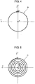
FIG. 4 shows an irradiation condition of a circular laser beam according to the exemplary embodiment. -
FIG. 5 shows an irradiation condition of a spiral laser beam according to the exemplary embodiment. -
FIG. 6A shows an example of a rotation angle identification unit of a holder according to the exemplary embodiment. -
FIG. 6B shows an example of a rotation angle identification unit of a holder according to the exemplary embodiment. -
FIG. 6C shows an example of a rotation angle identification unit of a holder according to the exemplary embodiment. -
FIG. 6D shows an example of a rotation angle identification unit of a holder according to the exemplary embodiment. -
FIG. 7 shows an origin adjusting hole in a body casing according to the exemplary embodiment. -
FIG. 8 shows a state in which an origin adjusting jig is set according to the exemplary embodiment. -
FIG. 9 illustrates origin calibration using the origin adjusting jig according to the exemplary embodiment. -
FIG. 10 illustrates a configuration of an origin of a conventional laser irradiation position. - Prior to describing an exemplary embodiment, problems in a conventional origin calibration method for an optical machining head will be briefly described.
- An optical machining head such as a laser machining head determines an irradiation position of light by operating optical elements such as a lens or a mirror. Accordingly, the irradiation position of light may be largely deviated in a case where positions of optical elements are shifted even in small amounts, and accuracy of the positions of the optical elements has a great influence on machining quality.
- Such an optical machining head is driven by a servomotor in most cases, and data relative to a rotation origin of the servomotor is stored using a battery. In case of a malfunction in a battery, a harness connecting the battery and a motor, or the motor itself, for example, positions of the optical elements need calibration.
- A conventional origin calibration method is described below with reference to
FIG. 10 . According to the conventional origin calibration method,sensor 110A configured to read a detection laser beam is provided to record in advance the irradiation intensity with which detection laser beamL2 irradiates sensor 110A whenoptical element 105 is disposed at a specific position. At the time of origin calibration,optical element 105 is moved to the specific position, and irradiation intensity of detection laser beam L2 at the moment is compared with the previous irradiation intensity to determine whetheroptical element 105 is shifted. In the case whereoptical element 105 is determined to be shifted, the irradiation intensity of emitted detection laser beam L2 is read, and an amount of displacement ofoptical element 105 is calculated backward with a specific algorithm to correct the positional deviation of optical element 105 (see PTL 1). - However, according to the above conventional origin calibration method for an optical machining head, an optical machining head such as a laser machining head determines an irradiation position of light by operating
optical element 105 such as a lens or a mirror. The irradiation position of detection laser beam L2 may be largely deviated in a case where a position ofoptical element 105 is shifted even in small amounts. Therefore, accuracy of the position ofoptical element 105 has a great influence on machining quality. - Hereinafter, a basic idea of an exemplary embodiment of the present disclosure will be described first, and then a detail thereof will be described with reference to the drawings.
-
Laser machining head 41 according to the present exemplary embodiment has a laser-beam LB shifting function to shift a focusing position of laser beam LB condensing at a nozzle tip, and is disposed on an optical path of laser beam LB. - Specifically, as shown in
FIG. 1 or2 ,laser machining head 41 includes firstparallel plate 17. Laser beam LB is incident on firstparallel plate 17. Firstparallel plate 17 rotates around first rotary axis a1, while maintaining a predetermined tilt angle with respect to first rotary axis a1 that is parallel to optical axis direction LD which is a passing direction of laser beam LB irradiatingmachining target 46. - Further,
laser machining head 41 includes secondparallel plate 19. Laser beam LB is incident on secondparallel plate 19. Secondparallel plate 19 rotates around second rotary axis a2, while maintaining the same tilt angle as firstparallel plate 17 with respect to second rotary axis a2 that is parallel to optical axis direction LD which is a passing direction of laser beam LB irradiatingmachining target 46. -
Laser machining head 41 further includes two motors (first servomotor 14 and second servomotor 21).First servomotor 14 rotates firstparallel plate 17, andsecond servomotor 21 rotates secondparallel plate 19.First servomotor 14 andsecond servomotor 21 respectively rotate firstparallel plate 17 and secondparallel plate 19 independently from each other. - Laser beam LB shifts in parallel by an amount determined by a thickness of first
parallel plate 17, a thickness of secondparallel plate 19, and a tilt angle of laser beam LB relative to an optical axis direction LD. Laser beam LB traces various paths on a two-dimensional irradiation plane by rotating firstparallel plate 17 and secondparallel plate 19. - A laser machining system and a laser machining head according to the present exemplary embodiment will be described below with reference to
FIGS. 1 to 9 . -
FIG. 1 shows a schematic configuration of the laser machining system.FIG. 2 shows a schematic configuration of the laser machining head.FIG. 3 illustrates an irradiation position of a laser beam.FIG. 4 shows an irradiation condition of a circular laser beam.FIG. 5 shows an irradiation condition of a spiral laser beam.FIGS. 6A to 6D each illustrate a rotation angle identification unit provided on a holder.FIG. 7 shows an origin adjusting hole in a body casing.FIG. 8 is an external view of setting an adjusting jig and adjusting an origin.FIG. 9 is a sectional view and an enlarged view ofFIG. 8 . - The laser machining system will be described first with reference to
FIG. 1 . With reference toFIG. 1 , laser machining system according to the present disclosure includeslaser machining head 41,manipulator 42,robot control device 43, andlaser oscillator 44. -
Laser machining head 41 is attached to a tip end ofmanipulator 42, andmanipulator 42 moveslaser machining head 41.Robot control device 43 controls movements of bothmanipulator 42 andlaser machining head 41.Laser oscillator 44 outputs laser beam LB. Laser beam LB output fromlaser oscillator 44 is guided tolaser machining head 41 byoptical fiber 45. The laser machining system according to the present disclosure performs machining ofmachining target 46 by irradiatingmachining target 46 with laser beam LB which is to be output fromlaser machining head 41.Robot control device 43 also controls an output oflaser oscillator 44. - Then,
laser machining head 41 will be described in detail with reference toFIG. 2 .Laser machining head 41 includesconnector 12.Laser machining head 41 is connected to optical fiber 45 (seeFIG. 1 ) throughconnector 12. -
Laser machining head 41 includescollimation lens 4 and focusinglens 5. Laser beam LB output fromoptical fiber 45 spreads out in a certain extent. Laser beam LB is then corrected to collimated light bycollimation lens 4. Laser beam LB corrected to collimated light is condensed on a machining point by focusinglens 5. -
Laser machining head 41 includeslens holder 3 to whichcollimation lens 4 and focusinglens 5 are fixed, andlens body 1 holdinglens holder 3.Collimation lens 4 and focusinglens 5 are fixed tolens holder 3. -
Laser machining head 41 includesfirst servomotor 14,first timing belt 15,first pulley 16, firstparallel plate 17, andfirst holder 18. A first optical unit is formed offirst servomotor 14,first timing belt 15,first pulley 16, firstparallel plate 17, andfirst holder 18. Firstparallel plate 17 is fixed infirst holder 18 having a cylindrical shape, both ends of which are held by bearings. - A parallel pin (not shown) is provided between first
parallel plate 17 andfirst holder 18 to fix a relative position between firstparallel plate 17 andfirst holder 18. Outer peripheral surface offirst holder 18 includesfirst pulley 16 andfirst timing belt 15.First servomotor 14 rotates firstparallel plate 17 fixed tofirst holder 18 throughfirst pulley 16 andfirst timing belt 15. -
Laser machining head 41 further includesshield holder 8,lever 9,nozzle holder 10,inner nozzle 11,connector 12,first member 23,second member 24, firstprotective glass 25, and secondprotective glass 26. - Specifically, first
parallel plate 17 rotates around first rotary axis a1 extending in the same direction as optical axis direction LD of laser beam LB to be output fromlaser machining head 41.First servomotor 14 is a brushless DC servomotor (AC servomotor) with a serial encoder of 50 W, for example. According to the present exemplary embodiment,first servomotor 14 is the same kind as a servomotor (not shown) employed asmanipulator 42 but is different from the servomotor in the output capacities. -
Laser machining head 41 includessecond servomotor 21, second timing belt 22,second pulley 20, secondparallel plate 19, andsecond holder 7. A second optical unit is formed ofsecond servomotor 21, second timing belt 22,second pulley 20, secondparallel plate 19, andsecond holder 7. Secondparallel plate 19 is fixed insecond holder 7 having a cylindrical shape, both ends of which are held by bearings. - A parallel pin (not shown) is provided between second
parallel plate 19 andsecond holder 7 to fix a relative position between secondparallel plate 19 andsecond holder 7. Outer peripheral surface ofsecond holder 7 includessecond pulley 20 and second timing belt 22.Second servomotor 21 rotates secondparallel plate 19 fixed tosecond holder 7 throughsecond pulley 20 and second timing belt 22. - Specifically, second
parallel plate 19 rotates around second rotary axis a2 extending in the same direction as optical axis direction LD of laser beam LB to be output fromlaser machining head 41. - As described above, the first optical unit and the second optical unit have the same configuration, and each component thereof is the same. With this configuration, two optical units (first optical unit and second optical unit) have the same response balance, thereby having an advantage of being easily controlled. First rotary axis a1 of the first optical unit and second rotary axis a2 of the second optical unit extend in the same direction. In addition, the first optical unit and the second optical unit are arranged symmetrically about the center of
body casing 6. In other words, the first optical unit and the second optical unit are arranged symmetrically about a plane perpendicular to first rotary axis a1. For example, inFIG. 2 , the first optical unit and the second optical unit are arranged symmetrically in the vertical direction. - In the layout shown in
FIG. 2 , a rotation direction of firstparallel plate 17 becomes opposite to a rotation direction of secondparallel plate 19, whenfirst servomotor 14 andsecond servomotor 21 rotate in the same direction. Accordingly,first servomotor 14 that drives firstparallel plate 17 is controlled to rotate in the direction opposite to the rotation direction ofsecond servomotor 21. - It is desirable that first rotary axis a1 and second rotary axis a2 extend not only in the same direction but are disposed on the same line in the first optical unit and the second optical unit so as to downsize
laser machining head 41 and increase an irradiation range oflaser machining head 41. - Laser beam LB having passed through focusing
lens 5 is refracted twice when passing through firstparallel plate 17. Laser beam LB shifts in parallel by an amount determined by a thickness of firstparallel plate 17, a tilt angle of firstparallel plate 17 with respect to first rotary axis a1, and a refractive index of firstparallel plate 17. Each of firstparallel plate 17 and secondparallel plate 19 according to the present exemplary embodiment is made of synthetic quartz of which thickness t is 13 mm, tilt angle with respect to the first rotary axis (or the second rotary axis) is 45°, and refractive index is 1.44963. Accordingly, laser beam LB having passed through firstparallel plate 17 shifts by 4.1 mm. Thereafter, the laser beam also shifts by 4.1 mm when passing through secondparallel plate 19. Therefore, a working range of laser beam LB according to the present exemplary embodiment is in a circle with a diameter of 16.4 mm. - An irradiation position of the laser beam having passed through first
parallel plate 17 and secondparallel plate 19 can be represented by two vectors each having a fixed magnitude and freely variable direction, as shown inFIG. 3 . Therefore, the irradiation position of the laser beam on machiningtarget 46 can be represented by the following equations.

- L: shift amount when the laser beam passes through one parallel plate
- θ1: rotation angle of first
parallel plate 17 - θ2: rotation angle of second
parallel plate 19 - Rotation angle θ1 of first
parallel plate 17 and rotation angle θ2 of secondparallel plate 19 are independently controlled by respective servomotors. Accordingly, laser beam LB can draw any figure within a movable range of laser beam LB. In particular, a figure such as a circle can be drawn smoothly by rotating a single servomotor or by continuously rotating two servomotors in the same direction at the same speed without a reverse operation of the servomotors. - In an actual operation, all patterns, which are welding patterns often used in remote welding such as a circle shown in
FIG. 4 and a spiral shown inFIG. 5 , can be drawn without a reverse operation of the motors. In other words, rotation of first rotary axis a1 and second rotary axis a2 in the same direction enables laser beam LB to draw a circular arc-shape, a circular shape, or a spiral shape on machining target 46 (seeFIG. 1 ) without a reverse operation of first rotary axis a1 and second rotary axis a2. - A phase difference of rotation angles between first rotary axis a1 and second rotary axis a2 determines a radius of a range capable of being irradiated with laser beam LB.
- As described above,
laser machining head 41 according to the present exemplary embodiment utilizes characteristics of laser beam LB to be shifted when passing through firstparallel plate 17 and secondparallel plate 19 made of a light transmissive glass or the like, and two plates of firstparallel plate 17 and secondparallel plate 19 are continuously arranged insidelaser machining head 41 in optical axis direction LD of laser beam LB. The rotation of firstparallel plate 17 and secondparallel plate 19 are independently controlled by respective servomotors (first servomotor 14 and second servomotor 21) to control a shift direction and a shift amount of laser beam LB. In this manner, accuracy of rotation angles of firstparallel plate 17 and secondparallel plate 19 greatly affects a shift direction and a shift amount of laser beam LB. Accordingly, it is obvious that the accuracy of the rotation angles also greatly affects laser machining. - For example, in case of a malfunction in a battery of a motor (
first servomotor 14 or second servomotor 21) for storing angle data such as an origin position, a harness connecting the motor (first servomotor 14 or second servomotor 21) and the battery, or the motor itself (first servomotor 14 or second servomotor 21), an error occurs in the rotation angle of firstparallel plate 17 or secondparallel plate 19. Such an error must be calibrated. - The following description is directed to one example of a method of adjusting the rotation angles of first
parallel plate 17 and secondparallel plate 19 according to the present disclosure. - The present disclosure relates to
laser machining head 41 configured to control an irradiation position of laser beam LB by rotating firstparallel plate 17 and secondparallel plate 19 in relation to each other. A rotation angle identification unit is provided onfirst holder 18 including firstparallel plate 17 to identify the rotation angle of firstparallel plate 17. - The rotation angle identification unit is provided at a fixed angle from the origin of first parallel plate 17 (at a fixed distance on the outer periphery of first holder 18) as viewed from the rotary axis, and thus a position of the origin of first
parallel plate 17 to be stored infirst holder 18 can be specified when a position of the rotation angle identification unit is specified. The origin of firstparallel plate 17 indicates the tilting direction of firstparallel plate 17 provided in a tilting manner with respect tofirst holder 18 and exists on the outer periphery offirst holder 18. The origin of firstparallel plate 17 and the rotation angle identification unit may coincide with each other. - The detailed configuration of the rotation angle identification unit will be described later with reference to
FIGS. 6A to 6D . - In the same manner as
first holder 18, a rotation angle identification unit is provided onsecond holder 7 including secondparallel plate 19 to identify the rotation angle of secondparallel plate 19. The rotation angle identification unit is provided at a fixed angle from the origin of second parallel plate 19 (at a fixed distance on the outer periphery of second holder 7) as viewed from the rotary axis, and thus a position of the origin of the secondparallel plate 19 to be stored insecond holder 7 can be specified when a position of the rotation angle identification unit is specified. The origin of secondparallel plate 19 indicates the tilting direction of secondparallel plate 19 provided in a tilting manner with respect tosecond holder 7 and exists on the outer periphery ofsecond holder 7. The origin of secondparallel plate 19 and the rotation angle identification unit may coincide with each other. - The rotation angle identification units provided respectively on
first holder 18 andsecond holder 7 are independently (or mutually adjusted) positioned relative to each other, thereby facilitating calibration of the relative positions of the origins of firstparallel plate 17 and secondparallel plate 19. - The rotation angle identification units of
first holder 18 andsecond holder 7 may have different shapes, but preferably have the same shape. - Then, the rotation angle identification unit configured to identify an angle on
first holder 18 orsecond holder 7 will be described with reference toFIGS. 6A to 6D . - The rotation angle identification unit is positioned in contact with origin adjusting jig 55 (see
FIGS. 8 and9 ), and thus is configured to have a surface (contact surface) to adaptively come in contact withorigin adjusting jig 55. In rotationangle identification unit 50 shown inFIG. 6A , a cut-out portion includes a contact surface, in rotationangle identification units FIGS. 6B and 6C , holes respectively include contact surfaces, and in rotationangle identification unit 53 shown inFIG. 6D , a projection includes a contact surface. - Here, rotation
angle identification unit 50 shown inFIG. 6A has a shape of a round cut out or an angular (triangle, quadrangle, polygon, or the like) cut out, rotationangle identification unit 51 shown inFIG. 6B has a shape of an angular hole, rotationangle identification unit 52 shown inFIG. 6C has a shape of a round hole, and rotationangle identification unit 53 shown inFIG. 6D has a shape of an angular projection. Rotationangle identification unit 53 inFIG. 6D may have a shape of a round projection. - Then, a configuration of
laser machining head 41 according to the present exemplary embodiment will be described with reference toFIGS. 7 and8 . -
FIGS. 7 and8 each show an external appearance oflaser machining head 41.Body casing 6 is provided withorigin adjusting hole 54 so that rotationangle identification units 50 to 53 of first holder 18 (seeFIGS. 6A to 6D ) and second holder 7 (seeFIGS. 6A to 6D ) housed insidelaser machining head 41 can be adjusted by a jig or the like from the outside.Origin adjusting hole 54 may be provided at any part ofbody casing 6, but is preferably provided at a center part ofbody casing 6. To determine a relative position oforigin adjusting jig 55 to be adapted to origin adjusting hole 54 (seeFIG. 8 ), diameters oforigin adjusting hole 54 andorigin adjusting jig 55 have the same shape and the same size, for example. The sizes of the diameters oforigin adjusting hole 54 andorigin adjusting jig 55 are determined such thatorigin adjusting jig 55 can be detachably inserted toorigin adjusting hole 54 andorigin adjusting jig 55 fits inorigin adjusting hole 54.Body casing 6 may include a plurality of origin adjusting holes 54. - For example, to adjust the origins,
first holder 18 andsecond holder 7 are adjusted by manual operation or the like so that a position of rotationangle identification unit 50 provided on each offirst holder 18 andsecond holder 7 coincides with a position oforigin adjusting hole 54 ofbody casing 6, and then as shown inFIG. 8 ,origin adjusting jig 55 is inserted throughorigin adjusting hole 54 ofbody casing 6 which is an outer wall oflaser machining head 41. -
FIG. 9 shows a sectional view and an enlarged view of a state in whichorigin adjusting jig 55 is inserted inbody casing 6. As shown inFIG. 9 , a surface of a cut-out portion of rotationangle identification unit 50 offirst holder 18 and a surface of a cut-out portion of rotationangle identification unit 50 ofsecond holder 7 are positioned by being pressed simultaneously by a tapered portion at a tip end oforigin adjusting jig 55. - At the same time,
origin adjusting jig 55 is also positioned with respect tobody casing 6. - Although
first holder 18 is provided with the cut-out portion of rotationangle identification unit 50 at a lower part offirst holder 18 as shown inFIG. 6A ,second holder 7 shown inFIG. 9 is provided with the cut-out portion of rotationangle identification unit 50 at an upper part ofsecond holder 7, unlike the shape shown inFIG. 6A . With reference toFIG. 9 , the cut-out portion of rotationangle identification unit 50 offirst holder 18 corresponds to the cut-out portion of rotationangle identification unit 50 ofsecond holder 7, andfirst holder 18 andsecond holder 7 are simultaneously positioned by a singleorigin adjusting jig 55. - With this configuration,
body casing 6 which is the outer wall oflaser machining head 41 includesorigin adjusting hole 54 that enables simultaneous alignment of the positions of the surface of rotation angle identification unit offirst holder 18 and the surface of the rotation angle identification unit ofsecond holder 7 by insertingorigin adjusting jig 55, andorigin adjusting jig 55 is inserted from the outer wall oflaser machining head 41 to simultaneously calibrate the origins of firstparallel plate 17 and secondparallel plate 19. - Accordingly, rotation
angle identification unit 50 is positioned with respect tobody casing 6, so that the origins of firstparallel plate 17 and secondparallel plate 19 are calibrated, and origin calibration oflaser machining head 41 emitting a laser beam can be easily performed. -
Laser machining head 41 according to the present disclosure controls an irradiation position of laser beam LB on machiningtarget 46, as shown inFIGS. 1 or2 .Laser machining head 41 includes: firstparallel plate 17 configured to shift laser beam LB incident on firstparallel plate 17;first holder 18 holding firstparallel plate 17 and having a first rotation angle identification unit (for example, rotationangle identification unit 50 or the like);first servomotor 14 configured to rotatefirst holder 18 around first rotary axis a1; secondparallel plate 19 configured to shift laser beam LB that has been shifted by firstparallel plate 17;second holder 7 holding secondparallel plate 19 and having second rotation angle identification unit (for example, rotationangle identification unit 50 or the like); andsecond servomotor 21 configured to rotatesecond holder 7 around second rotary axis a2. Firstparallel plate 17 and secondparallel plate 19 are disposed such that first rotary axis a1 and second rotary axis a2 extend in an identical direction. Inlaser machining head 41,first servomotor 14 rotates firstparallel plate 17 andsecond servomotor 21 rotates secondparallel plate 19 to control an irradiation position of laser beam LB on machiningtarget 46. The first rotation angle identification unit (rotationangle identification unit 50 or the like) has a positioning surface that allows positioning relative to firstparallel plate 17, and the second rotation angle identification unit has a positioning surface that allows positioning relative to secondparallel plate 19. - Further, according to the present disclosure,
origin adjusting hole 54 is formed on an outer wall oflaser machining head 41, as shown inFIG. 8 or the like. The positioning surface of the rotation angle identification unit (rotationangle identification unit 50 or the like) offirst holder 18 and the positioning surface of the rotation angle identification unit (rotationangle identification unit 50 or the like) ofsecond holder 7 are simultaneously aligned by insertingorigin adjusting jig 55 inorigin adjusting hole 54. - In an origin calibration method for
laser machining head 41 according to the present disclosure,origin adjusting jig 55 is inserted from the outer wall oflaser machining head 41, and an origin of firstparallel plate 17 and an origin of secondparallel plate 19 are calibrated simultaneously. - The present disclosure relates to a laser machining head configured to control an irradiation position of a laser beam by rotating a first parallel plate and a second parallel plate in relation to each other. A rotation angle identification unit is provided on each of a first holder including the first parallel plate and a second holder including the second parallel plate.
- With this configuration, origins of the first parallel plate and the second parallel plate can be relatively calibrated, and origin calibration of the laser machining head can be easily performed. Accordingly, the present disclosure is industrially useful as a laser machining head usable for remote laser machining, in which machining such as welding is performed by emitting a laser beam from a position away from a machining point, and an origin calibration method for the laser machining head.
-
- 1: lens body
- 3: lens holder
- 4: collimation lens
- 5: focusing lens
- 6: body casing
- 7: second holder
- 8: shield holder
- 9: lever
- 10: nozzle holder
- 11: inner nozzle
- 12: connector
- 14: first servomotor
- 15: first timing belt
- 16: first pulley
- 17: first parallel plate
- 18: first holder
- 19: second parallel plate
- 20: second pulley
- 21: second servomotor
- 22: second timing belt
- 23: first member
- 24: second member
- 25: first protective glass
- 26: second protective glass
- 41: laser machining head
- 42: manipulator
- 43: robot control device
- 44: laser oscillator
- 45: optical fiber
- 46: machining target
- 50, 51, 52, 53: rotation angle identification unit
- 54: origin adjusting hole
- 55: origin adjusting jig
- a1, a2: rotary axis
- t: thickness
- L2: detection laser beam
- LB: laser beam
- LD: optical axis direction
Claims (4)
- A laser machining head configured to control an irradiation position of a laser beam on a machining target, the laser machining head comprising:a first parallel plate configured to shift the laser beam incident on the first parallel plate;a first holder holding the first parallel plate and having a first rotation angle identification unit;a first motor configured to rotate the first holder around a first rotary axis,a second parallel plate configured to shift the laser beam that has been shifted by the first parallel plate;a second holder holding the second parallel plate and having a second rotation angle identification unit; anda second motor configured to rotate the second holder around a second rotary axis,wherein the first parallel plate and the second parallel plate are disposed such that the first rotary axis and the second rotary axis extend in an identical direction,the first motor rotates the first parallel plate and the second motor rotates the second parallel plate to control an irradiation position of the laser beam on the machining target,the first rotation angle identification unit has a positioning surface that allows positioning relative to the first parallel plate, andthe second rotation angle identification unit has a positioning surface that allows positioning relative to the second parallel plate.
- The laser machining head according to claim 1, wherein
an origin adjusting hole is formed on an outer wall of the laser machining head, and
a positioning surface of a rotation angle identification unit of the first holder and a positioning surface of a rotation angle identification unit of the second holder are simultaneously aligned by inserting an origin adjusting jig in the origin adjusting hole. - The laser machining head according to claim 1, wherein
the first rotary axis and the second rotary axis are co-linearly aligned with each other. - An origin calibration method for the laser machining head according to claim 1, wherein
an origin adjusting hole is formed on an outer wall of the laser machining head,
a positioning surface of a rotation angle identification unit of the first holder and a positioning surface of a rotation angle identification unit of the second holder are simultaneously aligned by inserting an origin adjusting jig in the origin adjusting hole, the method comprising:inserting the origin adjusting jig from the outer wall of the laser machining head; andsimultaneously calibrating an origin of the first parallel plate and an origin of the second parallel plate.
Applications Claiming Priority (2)
| Application Number | Priority Date | Filing Date | Title |
|---|---|---|---|
| JP2015176224 | 2015-09-08 | ||
| PCT/JP2016/003920 WO2017043042A1 (en) | 2015-09-08 | 2016-08-29 | Laser machining head and origin calibration method for same |
Publications (3)
| Publication Number | Publication Date |
|---|---|
| EP3348343A1 true EP3348343A1 (en) | 2018-07-18 |
| EP3348343A4 EP3348343A4 (en) | 2018-10-17 |
| EP3348343B1 EP3348343B1 (en) | 2019-07-10 |
Family
ID=58240673
Family Applications (1)
| Application Number | Title | Priority Date | Filing Date |
|---|---|---|---|
| EP16843911.5A Not-in-force EP3348343B1 (en) | 2015-09-08 | 2016-08-29 | Laser machining head and origin calibration method for same |
Country Status (5)
| Country | Link |
|---|---|
| US (1) | US10532426B2 (en) |
| EP (1) | EP3348343B1 (en) |
| JP (1) | JPWO2017043042A1 (en) |
| CN (1) | CN107708915B (en) |
| WO (1) | WO2017043042A1 (en) |
Families Citing this family (3)
| Publication number | Priority date | Publication date | Assignee | Title |
|---|---|---|---|---|
| CN110198804B (en) * | 2017-01-25 | 2020-12-08 | 松下知识产权经营株式会社 | Laser processing head and laser processing device using same |
| CN109909658B (en) * | 2018-09-21 | 2021-01-19 | 万向钱潮股份有限公司 | Automatic calibration device and method for welding robot and welding fixture |
| USD1019434S1 (en) * | 2022-06-14 | 2024-03-26 | Shenzhen Xiyang Technology Co., Ltd. | Laser head |
Family Cites Families (15)
| Publication number | Priority date | Publication date | Assignee | Title |
|---|---|---|---|---|
| US5001324A (en) * | 1989-09-14 | 1991-03-19 | General Electric Company | Precision joint tracking laser welding system |
| JP3157847B2 (en) * | 1991-03-12 | 2001-04-16 | 株式会社アマダ | Laser processing head device |
| JPH04352124A (en) * | 1991-05-30 | 1992-12-07 | Toshihiro Tsumura | Optical axis deflection device for optical equipment |
| JPH0669928U (en) * | 1993-03-16 | 1994-09-30 | 川崎重工業株式会社 | Laser beam oscillator device |
| IT1297360B1 (en) * | 1997-12-31 | 1999-09-01 | Prima Ind Spa | OPERATING HEAD FOR A LASER MACHINE |
| JP2003121764A (en) * | 2001-10-18 | 2003-04-23 | Nippon Telegr & Teleph Corp <Ntt> | Optical switch using rotary wedge prism and optical switch module |
| JP2004093926A (en) | 2002-08-30 | 2004-03-25 | Alnair Labs:Kk | Optical alignment system, optical alignment method, and regulating method of optical alignment system |
| JP2005128162A (en) | 2003-10-22 | 2005-05-19 | Pentax Corp | Optical axis regulating device of direct writing system |
| JP5178315B2 (en) | 2008-05-14 | 2013-04-10 | 株式会社ハーモニック・ドライブ・システムズ | Galvano scanner |
| EP2177299B1 (en) * | 2008-10-17 | 2013-07-31 | PRIMA INDUSTRIE S.p.A. | laser machine |
| DE102010049460A1 (en) * | 2010-09-13 | 2012-03-15 | Laser- Und Medizin-Technologie Gmbh, Berlin | trepanning |
| KR101290519B1 (en) * | 2011-09-07 | 2013-07-26 | 주식회사 이오테크닉스 | Laser processing apparatus |
| CN103143839A (en) * | 2011-12-07 | 2013-06-12 | 江苏大学 | Device and method for etching conductive layer on global positioning system (GPS) touch panel by infrared nanosecond pulse laser |
| JP5923320B2 (en) * | 2012-01-31 | 2016-05-24 | 株式会社アマダホールディングス | Laser processing head |
| US9889522B2 (en) | 2014-02-25 | 2018-02-13 | Panasonic Intellectual Property Management Co., Ltd. | Laser processing system |
-
2016
- 2016-08-29 EP EP16843911.5A patent/EP3348343B1/en not_active Not-in-force
- 2016-08-29 JP JP2017538860A patent/JPWO2017043042A1/en active Pending
- 2016-08-29 CN CN201680039732.9A patent/CN107708915B/en not_active Expired - Fee Related
- 2016-08-29 US US15/580,434 patent/US10532426B2/en active Active
- 2016-08-29 WO PCT/JP2016/003920 patent/WO2017043042A1/en active Application Filing
Also Published As
| Publication number | Publication date |
|---|---|
| US10532426B2 (en) | 2020-01-14 |
| EP3348343B1 (en) | 2019-07-10 |
| CN107708915A (en) | 2018-02-16 |
| CN107708915B (en) | 2019-06-18 |
| JPWO2017043042A1 (en) | 2018-07-26 |
| EP3348343A4 (en) | 2018-10-17 |
| US20180161922A1 (en) | 2018-06-14 |
| WO2017043042A1 (en) | 2017-03-16 |
Similar Documents
| Publication | Publication Date | Title |
|---|---|---|
| KR100882967B1 (en) | Laser welding apparatus and method for adjusting laser beam of the laser welding apparatus | |
| EP3348343B1 (en) | Laser machining head and origin calibration method for same | |
| JP6386501B2 (en) | Laser processing robot system and laser processing method | |
| EP3195989B1 (en) | Apparatus and method to optically locate workpiece for robotic operations | |
| US8520219B2 (en) | Non-contact sensor having improved laser spot | |
| EP3112073B1 (en) | Laser cutting system | |
| US20150241206A1 (en) | Shape measuring method and device | |
| US9470889B2 (en) | Laser scanning device | |
| US10322468B2 (en) | Apparatus for processing micro-component by using laser | |
| JP2009184081A (en) | Alignment device and holding device | |
| US11285564B2 (en) | Laser processing head and laser processing device using same | |
| JP2018040819A (en) | Method for manufacturing optical device | |
| EP2884302A1 (en) | Photoelectric sensor | |
| JP2007021551A (en) | Apparatus and system for laser welding | |
| EP3257618B1 (en) | Welding system & welding method | |
| CN107797270B (en) | Optical device, processing device, and article manufacturing method | |
| JP2019058912A (en) | Laser processing head and laser processing device provided with the same | |
| CN112526697A (en) | Lens alignment method | |
| CN111774725B (en) | Manipulator, laser processing equipment and control method of manipulator | |
| JP2014081333A (en) | Female thread shape measurement device and using method of the same | |
| WO2022137723A1 (en) | Laser processing device and method for adjusting focal position of laser beam using same | |
| JP2009025640A (en) | Method and device for adjusting optical axis of optical component, optical component adjusted by optical axis adjusting method, and manufacturing method of optical component | |
| EP4031317A2 (en) | Electromagnetic radiation system | |
| WO2023021138A1 (en) | Support for a transmissive optical element, laser processing device with such support, and process of adjusting the position of a transmissive optical element using such support | |
| JP2019147174A (en) | Processing point correction device of laser emission device, laser emission device and laser processor |
Legal Events
| Date | Code | Title | Description |
|---|---|---|---|
| STAA | Information on the status of an ep patent application or granted ep patent |
Free format text: STATUS: THE INTERNATIONAL PUBLICATION HAS BEEN MADE |
|
| PUAI | Public reference made under article 153(3) epc to a published international application that has entered the european phase |
Free format text: ORIGINAL CODE: 0009012 |
|
| STAA | Information on the status of an ep patent application or granted ep patent |
Free format text: STATUS: REQUEST FOR EXAMINATION WAS MADE |
|
| 17P | Request for examination filed |
Effective date: 20171127 |
|
| AK | Designated contracting states |
Kind code of ref document: A1 Designated state(s): AL AT BE BG CH CY CZ DE DK EE ES FI FR GB GR HR HU IE IS IT LI LT LU LV MC MK MT NL NO PL PT RO RS SE SI SK SM TR |
|
| AX | Request for extension of the european patent |
Extension state: BA ME |
|
| A4 | Supplementary search report drawn up and despatched |
Effective date: 20180918 |
|
| RIC1 | Information provided on ipc code assigned before grant |
Ipc: B23K 26/064 20140101AFI20180912BHEP Ipc: B23K 26/08 20140101ALI20180912BHEP Ipc: G02B 26/08 20060101ALI20180912BHEP |
|
| DAV | Request for validation of the european patent (deleted) | ||
| DAX | Request for extension of the european patent (deleted) | ||
| GRAP | Despatch of communication of intention to grant a patent |
Free format text: ORIGINAL CODE: EPIDOSNIGR1 |
|
| STAA | Information on the status of an ep patent application or granted ep patent |
Free format text: STATUS: GRANT OF PATENT IS INTENDED |
|
| INTG | Intention to grant announced |
Effective date: 20190429 |
|
| GRAS | Grant fee paid |
Free format text: ORIGINAL CODE: EPIDOSNIGR3 |
|
| GRAA | (expected) grant |
Free format text: ORIGINAL CODE: 0009210 |
|
| STAA | Information on the status of an ep patent application or granted ep patent |
Free format text: STATUS: THE PATENT HAS BEEN GRANTED |
|
| AK | Designated contracting states |
Kind code of ref document: B1 Designated state(s): AL AT BE BG CH CY CZ DE DK EE ES FI FR GB GR HR HU IE IS IT LI LT LU LV MC MK MT NL NO PL PT RO RS SE SI SK SM TR |
|
| REG | Reference to a national code |
Ref country code: GB Ref legal event code: FG4D |
|
| REG | Reference to a national code |
Ref country code: CH Ref legal event code: EP Ref country code: AT Ref legal event code: REF Ref document number: 1153005 Country of ref document: AT Kind code of ref document: T Effective date: 20190715 |
|
| REG | Reference to a national code |
Ref country code: DE Ref legal event code: R096 Ref document number: 602016016836 Country of ref document: DE |
|
| REG | Reference to a national code |
Ref country code: IE Ref legal event code: FG4D |
|
| PGFP | Annual fee paid to national office [announced via postgrant information from national office to epo] |
Ref country code: DE Payment date: 20190822 Year of fee payment: 4 |
|
| REG | Reference to a national code |
Ref country code: NL Ref legal event code: MP Effective date: 20190710 |
|
| REG | Reference to a national code |
Ref country code: LT Ref legal event code: MG4D |
|
| REG | Reference to a national code |
Ref country code: AT Ref legal event code: MK05 Ref document number: 1153005 Country of ref document: AT Kind code of ref document: T Effective date: 20190710 |
|
| PG25 | Lapsed in a contracting state [announced via postgrant information from national office to epo] |
Ref country code: NO Free format text: LAPSE BECAUSE OF FAILURE TO SUBMIT A TRANSLATION OF THE DESCRIPTION OR TO PAY THE FEE WITHIN THE PRESCRIBED TIME-LIMIT Effective date: 20191010 Ref country code: AT Free format text: LAPSE BECAUSE OF FAILURE TO SUBMIT A TRANSLATION OF THE DESCRIPTION OR TO PAY THE FEE WITHIN THE PRESCRIBED TIME-LIMIT Effective date: 20190710 Ref country code: HR Free format text: LAPSE BECAUSE OF FAILURE TO SUBMIT A TRANSLATION OF THE DESCRIPTION OR TO PAY THE FEE WITHIN THE PRESCRIBED TIME-LIMIT Effective date: 20190710 Ref country code: SE Free format text: LAPSE BECAUSE OF FAILURE TO SUBMIT A TRANSLATION OF THE DESCRIPTION OR TO PAY THE FEE WITHIN THE PRESCRIBED TIME-LIMIT Effective date: 20190710 Ref country code: FI Free format text: LAPSE BECAUSE OF FAILURE TO SUBMIT A TRANSLATION OF THE DESCRIPTION OR TO PAY THE FEE WITHIN THE PRESCRIBED TIME-LIMIT Effective date: 20190710 Ref country code: LT Free format text: LAPSE BECAUSE OF FAILURE TO SUBMIT A TRANSLATION OF THE DESCRIPTION OR TO PAY THE FEE WITHIN THE PRESCRIBED TIME-LIMIT Effective date: 20190710 Ref country code: PT Free format text: LAPSE BECAUSE OF FAILURE TO SUBMIT A TRANSLATION OF THE DESCRIPTION OR TO PAY THE FEE WITHIN THE PRESCRIBED TIME-LIMIT Effective date: 20191111 Ref country code: NL Free format text: LAPSE BECAUSE OF FAILURE TO SUBMIT A TRANSLATION OF THE DESCRIPTION OR TO PAY THE FEE WITHIN THE PRESCRIBED TIME-LIMIT Effective date: 20190710 Ref country code: BG Free format text: LAPSE BECAUSE OF FAILURE TO SUBMIT A TRANSLATION OF THE DESCRIPTION OR TO PAY THE FEE WITHIN THE PRESCRIBED TIME-LIMIT Effective date: 20191010 |
|
| PG25 | Lapsed in a contracting state [announced via postgrant information from national office to epo] |
Ref country code: LV Free format text: LAPSE BECAUSE OF FAILURE TO SUBMIT A TRANSLATION OF THE DESCRIPTION OR TO PAY THE FEE WITHIN THE PRESCRIBED TIME-LIMIT Effective date: 20190710 Ref country code: ES Free format text: LAPSE BECAUSE OF FAILURE TO SUBMIT A TRANSLATION OF THE DESCRIPTION OR TO PAY THE FEE WITHIN THE PRESCRIBED TIME-LIMIT Effective date: 20190710 Ref country code: GR Free format text: LAPSE BECAUSE OF FAILURE TO SUBMIT A TRANSLATION OF THE DESCRIPTION OR TO PAY THE FEE WITHIN THE PRESCRIBED TIME-LIMIT Effective date: 20191011 Ref country code: AL Free format text: LAPSE BECAUSE OF FAILURE TO SUBMIT A TRANSLATION OF THE DESCRIPTION OR TO PAY THE FEE WITHIN THE PRESCRIBED TIME-LIMIT Effective date: 20190710 Ref country code: RS Free format text: LAPSE BECAUSE OF FAILURE TO SUBMIT A TRANSLATION OF THE DESCRIPTION OR TO PAY THE FEE WITHIN THE PRESCRIBED TIME-LIMIT Effective date: 20190710 Ref country code: IS Free format text: LAPSE BECAUSE OF FAILURE TO SUBMIT A TRANSLATION OF THE DESCRIPTION OR TO PAY THE FEE WITHIN THE PRESCRIBED TIME-LIMIT Effective date: 20191110 |
|
| PG25 | Lapsed in a contracting state [announced via postgrant information from national office to epo] |
Ref country code: TR Free format text: LAPSE BECAUSE OF FAILURE TO SUBMIT A TRANSLATION OF THE DESCRIPTION OR TO PAY THE FEE WITHIN THE PRESCRIBED TIME-LIMIT Effective date: 20190710 |
|
| PG25 | Lapsed in a contracting state [announced via postgrant information from national office to epo] |
Ref country code: RO Free format text: LAPSE BECAUSE OF FAILURE TO SUBMIT A TRANSLATION OF THE DESCRIPTION OR TO PAY THE FEE WITHIN THE PRESCRIBED TIME-LIMIT Effective date: 20190710 Ref country code: PL Free format text: LAPSE BECAUSE OF FAILURE TO SUBMIT A TRANSLATION OF THE DESCRIPTION OR TO PAY THE FEE WITHIN THE PRESCRIBED TIME-LIMIT Effective date: 20190710 Ref country code: EE Free format text: LAPSE BECAUSE OF FAILURE TO SUBMIT A TRANSLATION OF THE DESCRIPTION OR TO PAY THE FEE WITHIN THE PRESCRIBED TIME-LIMIT Effective date: 20190710 Ref country code: DK Free format text: LAPSE BECAUSE OF FAILURE TO SUBMIT A TRANSLATION OF THE DESCRIPTION OR TO PAY THE FEE WITHIN THE PRESCRIBED TIME-LIMIT Effective date: 20190710 Ref country code: IT Free format text: LAPSE BECAUSE OF FAILURE TO SUBMIT A TRANSLATION OF THE DESCRIPTION OR TO PAY THE FEE WITHIN THE PRESCRIBED TIME-LIMIT Effective date: 20190710 |
|
| PG25 | Lapsed in a contracting state [announced via postgrant information from national office to epo] |
Ref country code: MC Free format text: LAPSE BECAUSE OF FAILURE TO SUBMIT A TRANSLATION OF THE DESCRIPTION OR TO PAY THE FEE WITHIN THE PRESCRIBED TIME-LIMIT Effective date: 20190710 Ref country code: LU Free format text: LAPSE BECAUSE OF NON-PAYMENT OF DUE FEES Effective date: 20190829 Ref country code: IS Free format text: LAPSE BECAUSE OF FAILURE TO SUBMIT A TRANSLATION OF THE DESCRIPTION OR TO PAY THE FEE WITHIN THE PRESCRIBED TIME-LIMIT Effective date: 20200224 Ref country code: SM Free format text: LAPSE BECAUSE OF FAILURE TO SUBMIT A TRANSLATION OF THE DESCRIPTION OR TO PAY THE FEE WITHIN THE PRESCRIBED TIME-LIMIT Effective date: 20190710 Ref country code: SK Free format text: LAPSE BECAUSE OF FAILURE TO SUBMIT A TRANSLATION OF THE DESCRIPTION OR TO PAY THE FEE WITHIN THE PRESCRIBED TIME-LIMIT Effective date: 20190710 Ref country code: CZ Free format text: LAPSE BECAUSE OF FAILURE TO SUBMIT A TRANSLATION OF THE DESCRIPTION OR TO PAY THE FEE WITHIN THE PRESCRIBED TIME-LIMIT Effective date: 20190710 Ref country code: LI Free format text: LAPSE BECAUSE OF NON-PAYMENT OF DUE FEES Effective date: 20190831 Ref country code: CH Free format text: LAPSE BECAUSE OF NON-PAYMENT OF DUE FEES Effective date: 20190831 |
|
| REG | Reference to a national code |
Ref country code: BE Ref legal event code: MM Effective date: 20190831 |
|
| REG | Reference to a national code |
Ref country code: DE Ref legal event code: R097 Ref document number: 602016016836 Country of ref document: DE |
|
| PLBE | No opposition filed within time limit |
Free format text: ORIGINAL CODE: 0009261 |
|
| STAA | Information on the status of an ep patent application or granted ep patent |
Free format text: STATUS: NO OPPOSITION FILED WITHIN TIME LIMIT |
|
| PG2D | Information on lapse in contracting state deleted |
Ref country code: IS |
|
| PG25 | Lapsed in a contracting state [announced via postgrant information from national office to epo] |
Ref country code: IE Free format text: LAPSE BECAUSE OF NON-PAYMENT OF DUE FEES Effective date: 20190829 |
|
| 26N | No opposition filed |
Effective date: 20200603 |
|
| PG25 | Lapsed in a contracting state [announced via postgrant information from national office to epo] |
Ref country code: BE Free format text: LAPSE BECAUSE OF NON-PAYMENT OF DUE FEES Effective date: 20190831 Ref country code: SI Free format text: LAPSE BECAUSE OF FAILURE TO SUBMIT A TRANSLATION OF THE DESCRIPTION OR TO PAY THE FEE WITHIN THE PRESCRIBED TIME-LIMIT Effective date: 20190710 |
|
| PG25 | Lapsed in a contracting state [announced via postgrant information from national office to epo] |
Ref country code: FR Free format text: LAPSE BECAUSE OF NON-PAYMENT OF DUE FEES Effective date: 20190910 |
|
| REG | Reference to a national code |
Ref country code: DE Ref legal event code: R119 Ref document number: 602016016836 Country of ref document: DE |
|
| GBPC | Gb: european patent ceased through non-payment of renewal fee |
Effective date: 20200829 |
|
| PG25 | Lapsed in a contracting state [announced via postgrant information from national office to epo] |
Ref country code: CY Free format text: LAPSE BECAUSE OF FAILURE TO SUBMIT A TRANSLATION OF THE DESCRIPTION OR TO PAY THE FEE WITHIN THE PRESCRIBED TIME-LIMIT Effective date: 20190710 |
|
| PG25 | Lapsed in a contracting state [announced via postgrant information from national office to epo] |
Ref country code: HU Free format text: LAPSE BECAUSE OF FAILURE TO SUBMIT A TRANSLATION OF THE DESCRIPTION OR TO PAY THE FEE WITHIN THE PRESCRIBED TIME-LIMIT; INVALID AB INITIO Effective date: 20160829 Ref country code: DE Free format text: LAPSE BECAUSE OF NON-PAYMENT OF DUE FEES Effective date: 20210302 Ref country code: MT Free format text: LAPSE BECAUSE OF FAILURE TO SUBMIT A TRANSLATION OF THE DESCRIPTION OR TO PAY THE FEE WITHIN THE PRESCRIBED TIME-LIMIT Effective date: 20190710 |
|
| PG25 | Lapsed in a contracting state [announced via postgrant information from national office to epo] |
Ref country code: GB Free format text: LAPSE BECAUSE OF NON-PAYMENT OF DUE FEES Effective date: 20200829 |
|
| PG25 | Lapsed in a contracting state [announced via postgrant information from national office to epo] |
Ref country code: MK Free format text: LAPSE BECAUSE OF FAILURE TO SUBMIT A TRANSLATION OF THE DESCRIPTION OR TO PAY THE FEE WITHIN THE PRESCRIBED TIME-LIMIT Effective date: 20190710 |