EP3348002B1 - Zentralisiertes leistungsmessgerät und zentralisiertes leistungsberechnungsverfahren - Google Patents
Zentralisiertes leistungsmessgerät und zentralisiertes leistungsberechnungsverfahren Download PDFInfo
- Publication number
- EP3348002B1 EP3348002B1 EP15903348.9A EP15903348A EP3348002B1 EP 3348002 B1 EP3348002 B1 EP 3348002B1 EP 15903348 A EP15903348 A EP 15903348A EP 3348002 B1 EP3348002 B1 EP 3348002B1
- Authority
- EP
- European Patent Office
- Prior art keywords
- power calculation
- samples
- request
- power
- requests
- Prior art date
- Legal status (The legal status is an assumption and is not a legal conclusion. Google has not performed a legal analysis and makes no representation as to the accuracy of the status listed.)
- Active
Links
Images



Classifications
-
- H—ELECTRICITY
- H04—ELECTRIC COMMUNICATION TECHNIQUE
- H04B—TRANSMISSION
- H04B17/00—Monitoring; Testing
- H04B17/10—Monitoring; Testing of transmitters
- H04B17/11—Monitoring; Testing of transmitters for calibration
- H04B17/14—Monitoring; Testing of transmitters for calibration of the whole transmission and reception path, e.g. self-test loop-back
-
- G—PHYSICS
- G06—COMPUTING OR CALCULATING; COUNTING
- G06F—ELECTRIC DIGITAL DATA PROCESSING
- G06F1/00—Details not covered by groups G06F3/00 - G06F13/00 and G06F21/00
- G06F1/26—Power supply means, e.g. regulation thereof
- G06F1/28—Supervision thereof, e.g. detecting power-supply failure by out of limits supervision
-
- G—PHYSICS
- G05—CONTROLLING; REGULATING
- G05B—CONTROL OR REGULATING SYSTEMS IN GENERAL; FUNCTIONAL ELEMENTS OF SUCH SYSTEMS; MONITORING OR TESTING ARRANGEMENTS FOR SUCH SYSTEMS OR ELEMENTS
- G05B15/00—Systems controlled by a computer
- G05B15/02—Systems controlled by a computer electric
-
- H—ELECTRICITY
- H04—ELECTRIC COMMUNICATION TECHNIQUE
- H04B—TRANSMISSION
- H04B17/00—Monitoring; Testing
- H04B17/10—Monitoring; Testing of transmitters
- H04B17/15—Performance testing
- H04B17/18—Monitoring during normal operation
-
- H—ELECTRICITY
- H04—ELECTRIC COMMUNICATION TECHNIQUE
- H04W—WIRELESS COMMUNICATION NETWORKS
- H04W52/00—Power management, e.g. Transmission Power Control [TPC] or power classes
- H04W52/04—Transmission power control [TPC]
-
- H—ELECTRICITY
- H02—GENERATION; CONVERSION OR DISTRIBUTION OF ELECTRIC POWER
- H02J—ELECTRIC POWER NETWORKS; CIRCUIT ARRANGEMENTS OR SYSTEMS FOR SUPPLYING OR DISTRIBUTING ELECTRIC POWER; SYSTEMS FOR STORING ELECTRIC ENERGY
- H02J13/00—Circuit arrangements for providing remote monitoring or remote control of equipment in a power distribution network
Definitions
- the present disclosure generally relates to the technical field of telecommunication, and particularly to a centralized power meter and a centralized power calculation method for a plurality of digital sample sources.
- power meters may be used for power metering, which is required for various purposes, such as power gain control, signal glitch suppression, debug etc.
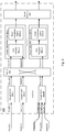
- Fig. 1 illustratively shows a schematic structure diagram of a conventional power meter.
- the power meter 100 may comprise: a sampling unit 101 for obtaining samples from a power metering source ("source" for short, the same below); a sample buffer 103 for buffering the samples from the source and triggering a request for power calculation of the buffered samples in response to the buffered samples; a power calculation engine 105 for retrieving the samples from the sample buffer in response to the request and performing power calculation of the retrieved samples.
- source for short, the same below
- a sample buffer 103 for buffering the samples from the source and triggering a request for power calculation of the buffered samples in response to the buffered samples
- a power calculation engine 105 for retrieving the samples from the sample buffer in response to the request and performing power calculation of the retrieved samples.
- the sample buffer 103 may be optional. That is, samples output from the sampling unit 101 may be directly transmitted to the power calculation engine 105, and the power calculation engine 105 may perform power calculation of the retrieved samples.
- P avg_db represents the average power in logarithmic units (e.g.,
- the results of the calculations according to equations (1)-(3) will provide indicators of instantaneous signal power in the power metering period.
- a subsequent power metering period may start immediately after a current one, or after some delay has elapsed, whereby the indicator of the instantaneous power is refreshed.
- Such repeated power metering over consecutive periods may proceed during operation of the signal processing circuit, so that an up-to-date indicator of the instantaneous power at the source is available at all times.
- a measure of the total signal energy may be obtained by accumulating calculated power values for a plurality of power metering periods.
- the power calculation engine is a main resource consumption part of the power meter.
- the power meter may be inserted to any power trace point that needs the power metering.
- Fig. 2 illustratively shows several exemplary power trace points where respective conventional power meters may be located as required in an exemplary TDD (Time Division Duplexing) digital front end signal processing circuit 200.
- TDD Time Division Duplexing
- the total resource consumption of the power meters in the whole circuit becomes considerable. Furthermore, the distributed arrangement of power meters in which at least one power meter is located at each trace point may negatively affect the size of the whole circuit.
- the distributed arrangement of power meters as described above causes a waste of resource, since the power meters disposed on some power trace points may not be active at all times, e.g., in TDD, the power meters respectively for UL (Uplink) / DL (Downlink) work in different time slots; and generally, most of the power meters do not need to perform a full-time power metering.
- WO2014/040608 A1 describes a background art of uplink path integrity detection in distributed antenna systems.
- WO2014/199380A1 describes a background art of time-division duplexing (TDD) in distributed communications systems.
- an object of the present disclosure is to provide a centralized power meter and a centralized power calculation method for a plurality of sources, which may reduce the number of the power calculation cores needed in the circuit, and thus reduce the resource consumption and the size of the circuit.
- a premise of proposing technical solutions of the present disclosure consists in that there is a possibility to share the power calculation core, at least because
- the technical solutions of the present disclosure should consider the fact that sharing the power calculation core needs to meet a processing latency requirement of the power meter. More precisely, some power meter, e.g. the power meter for the automatic gain control or variable control association purpose etc., needs its power calculation core to immediately get its power calculation result in a specified period once the last sample goes into the power calculation core, so as to avoid performance degrade; other power meters, e.g. a power meter for debugging purposes, are not latency-sensitive.
- the technical solutions of the present disclosure enable the shared power calculation core to handle different power calculation tasks with priorities, or in other words, to support QoS (Quality of Service).
- Hardware implementations of the presently disclosed techniques may include or encompass, without limitation, digital signal processor (DSP) hardware, a reduced instruction set processor, hardware (e.g., digital or analog) circuitry including but not limited to application specific integrated circuit(s) (ASIC) and/or field programmable gate array(s) (FPGA(s)), and (where appropriate) state machines capable of performing such functions.
- DSP digital signal processor
- ASIC application specific integrated circuit
- FPGA field programmable gate array
- Fig. 3 illustratively shows a schematic structure diagram of a centralized power meter (or instantaneous power sensing device) 300 according to an embodiment of the present disclosure.
- the centralized power meter 300 in Fig. 3 only illustratively show elements contributing to the present disclosure, some well-known elements, such as a sampling unit in the power meter, are omitted in Fig. 3 in order not to obscure the structure diagram of the centralized power meter according to the present embodiment.
- the centralized power meter 300 comprises:
- the N sources at respective power trace points are sources for which power calculation is required for various purposes in practice, such as power gain control, signal glitch suppression, debug etc. Different sources may have different requirements for obtaining their power calculation results. For example, the source at the power trace point for the automatic gain control purpose etc. needs to immediately get its power calculation result once the last sample goes into the power calculation core; unlike this, the source at the power trace point for the debug purpose is not sensitive to the time of obtaining its power calculation result.
- Different power calculation requirements of the N sources may be well met by assigning a priority to each of the N sources.
- the priorities may be independently assigned to the respective N sources, according to the power calculation requirements of the respective N sources.
- the priority of the source is associated with a source ID of the source.
- the centralized power meter 300 further comprises N sampling units respectively for the N sources, although they are not shown in Fig. 3 .
- Each sampling unit is configured to obtain, from one of the N sources, samples for which power calculation is required.
- the sampling unit may obtain the samples in a predetermined period on the source for which the power calculation is required.
- the sampling unit may be an IQ sampling unit which performs an IQ sampling process.
- the skilled in the art may select an appropriate sampling unit in practice, which is not limited by the present disclosure.
- the sampling unit may transfer the obtained samples to the sample buffer 303.
- sample buffer 303 there may be one sample buffer 303 for the samples from each source.
- the sample buffers 303-1 and 303-2 respectively for the samples from Source 1 and Source 2 in Fig. 3 exemplarily show this case.
- the samples from the plurality of sources may share the same sample buffer 303. Therefore in this case, the number of the sample buffers 303 in the centralized power meter may be reduced to be less than the number of the sources.
- the sample buffer 303-M for the samples respectively from Sources N-2, N-1 and N in Fig. 3 exemplarily show this case. It should be understood that a shared sample buffer may be used for samples from any plurality of sources, as long as the plurality of sources are required to be sampled in different time periods, which is not limited to the examples shown in Fig. 3 .
- a single sample buffer may be shared by sources intended to serve a debugging purpose, since typically the sources with the debug purpose do not need power calculation in the same power calculation interval.
- the sample buffer 303 may be used for buffering the samples before power calculation may be performed on the samples, and trigger a request for power calculation of the buffered samples in response to the buffered samples.
- the request may contain the source ID of the source from which the samples are obtained, and the corresponding priority associated with the source ID.
- Size requirements of the sample buffers 303 for the sources with different priorities may be different. For example, for a source with a higher priority, the size of the sample buffer may be smaller, since the samples buffered will be retrieved soon to be calculated in the power calculation core; however, for a source with a lower priority, the size of the sample buffer should be sufficient to buffer all the samples during a power calculation period.
- the sample buffer 303 may transfer the triggered request to the switch 305.
- the switch 305 may route the requests from the M sample buffers 303-1,...,303-M to a plurality of power calculation cores 307-1,...,307-P according to a load balancing policy.
- the switch 305 may establish a connection between the sample buffer 303 and the power calculation core 307 according to a load balancing policy, and route the request received from the sample buffer 303 to the power calculation core 307 via the established connection.
- the switch 305 establishes connections between the sample buffer 303-1 and the power calculation core 307-1, between the sample buffer 303-M and the power calculation core 307-1, and between the sample buffer 303-2 and the power calculation core 307-P by taking the load balancing into account; and respectively route Requests 1 and M to the power calculation core 307-1 and route Request 2 to the power calculation core 307-P via the three connections.
- the switch 305 may support dynamically changing the connection between the sample buffer 303 and the power calculation core 307 based on the load balancing.
- the switch 305 may establish a connection to a power calculation core 307 with the least workload, or the switch 305 may change the connection from a heavy-loaded power calculation core to a relatively empty power calculation core.
- the number P of the power calculation cores 307 depends on the capacity of the power calculation core simultaneously dealing with the requests from the M sample buffers 303.
- the power calculation cores 307 may be implemented as integrated circuits, or parts of a common integrated circuit, whereby the chip resource consumption normally is in a direct relationship with P.
- the power calculation core 307 may retrieve the samples from the sample buffer 303 via the connection established by the switch 305, and may do so in an order of the corresponding priorities of the routed requests, in response to the requests routed to the power calculation core 307. The power calculation core 307 may then perform power calculation of the retrieved samples in accordance with above equations (1)-(3) or equivalent relationships.
- the power calculation core 307 comprises a QoS scheduler 3071 and a power calculation engine 3073.
- the QoS scheduler 3071 may schedule the requests routed to the power calculation core 307 in the order of the corresponding priorities of the routed requests to select the routed requests one by one, and instruct the power calculation engine 3073 to serve the selected request, which may comprise: retrieving, from the sample buffer 303, the samples of which the request for power calculation is selected, and performing the power calculation on the retrieved samples.
- the power calculation engine 3073 may retrieve, from the sample buffer 303, the samples of which the request for power calculation is selected and to perform the power calculation of the retrieved samples.
- the power calculation engine 3073 will serve the selected request for a predetermined period, which may be called a serving period. During the serving period, the power calculation engine 3073 may retrieve the samples corresponding to the request from the sample buffer, and perform the power calculation of the retrieved samples.
- the scheduling process of the QoS scheduler 3071 is much quicker than the serving period of the power calculation engine 3073. Therefore, it may be considered that the QoS scheduler 3071 performs a new round of scheduling to select a new request for the power calculation engine 3073 at the end/start of each serving period of the power calculation engine 3073.
- the QoS scheduler 3071-1 may schedule Requests 1 and M to firstly select Request 1 and instruct the power calculation engine 3073-1 to serve Request 1 in its serving period; and the power calculation engine 3073-1 may retrieve the samples of Source 1 from the sample buffer 303-1 and perform the power calculation of the retrieved samples in its serving period.
- the QoS scheduler 3071-1 may schedule to select Request M and instruct the power calculation engine 3073-1 to serve Request M in the next serving period; and the power calculation engine 3073-1 may retrieve the samples from the sample buffer 303-M and perform the power calculation of the retrieved samples in its next serving period.
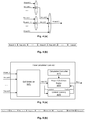
- Fig. 4(a) illustratively shows a QoS scheduling mechanism of a QoS scheduler in a centralized power meter according to an embodiment of the present disclosure
- Fig. 4(b) illustratively shows a QoS scheduling sequence output by the QoS scheduler of Fig. 4(a) .
- the QoS scheduler 3071 included in the power calculation core 307 has a two-level scheduling mechanism. On the first level, a plurality of requests are divided into several groups, each group consisting of the requests with the same priority; and one request is selected from each group using a round-robin (RR) method; and on the second level, the requests from the several groups with different priorities are selected in the order of their priorities using a strict priority (SP) method.
- the QoS scheduler 3071 may schedule the plurality of requests routed to the power calculation core 307 in the order of the corresponding priorities of the plurality of requests to select the plurality of requests one by one, in which the requests with the same priority are selected in the RR way.
- Fig. 4(a) shows a plurality of requests being received in a time period, which may be regarded as a static scenario, i.e., no more requests are received in this time period. It is assumed that Requests 1, 2,... have the same high priority; Requests i, i+1... have the same medium priority; and Request j has a low priority, where i, j are integers representing numbers of the requests, and i ⁇ j. Initially on the first level, Requests 1, 2,... with the same high priority are grouped together and Request 1 is firstly selected by the RR method; Requests i, i+1,...
- Request i is firstly selected by the RR method; and on the second level, Requests 1, i and j are selected in the order of their priorities using the SP method, and thus Request 1 with the high priority is output.
- Request 2 is selected by the RR method on the first level, and is further selected by the SP method on the second level, and thus Request 2 with the high priority is output, and so on.
- Requests 1, 2,..., i, i+1,..., j are selected from the QoS scheduler 3071 one by one in their priorities, as shown in Fig. 4(b) .
- Figs. 4(a) and 4(b) show three priorities as an example for illustration, the present disclosure is not limited to this situation. Any number of priorities may be possible.
- the QoS scheduling mechanism of Fig. 4(a) may also be applied to a dynamic scenario, in which the requests are continuously received over time.
- the QoS scheduler 3071 performs a new round of the two-level scheduling mechanism of Fig. 4(a) to select a new request for the power calculation engine 3073 every end/start of the serving period of the power calculation engine 3073.
- Fig. 3 shows a simple example of QoS scheduling and power calculation in the power calculation core, in which there are a less number of requests with different priorities routed to the power calculation core 307 in a static scenario; and the power calculation of the samples corresponding to the request with a higher priority can be completed in the power calculation engine 3073 during its serving period, and then the QoS scheduler 3071 performs a new scheduling to select a request with a lower priority.
- the power calculation core 307 may continuously receive a plurality of requests with the same and different priorities which is a dynamic process, and the power calculation of samples may be interrupted at the end of the serving period of the power calculation engine 3073 by a newly selected request with a priority higher than that of the request for power calculation of the samples.
- Fig. 5(a) illustratively shows a schematic structure diagram of a power calculation core 307 in a centralized power meter according to an embodiment of the present disclosure. Same reference numbers refer to elements which are same or similar to those elements in Fig. 3 , and similar descriptions thereof may be omitted for simplicity.
- the power calculation core 307 may comprise a QoS scheduler 3071, a calculation controller 3072, a power calculation engine 3073 and a context memory 3075.
- the QoS scheduler 3071 may schedule, at the end of the serving period of the power calculation engine 3073, the plurality of requests routed to the power calculation core 307 by the two-level QoS scheduling mechanism as previously described in conjunction with Fig. 4(a) , so as to select a new request (e.g., Request 1) to be served by the power calculation engine 3073.
- a new request e.g., Request 1
- the context memory 3075 may store, from the power calculation engine 3073, the power calculation context for the request currently served by power calculation engine 3073, under the control of the calculation controller 3072.
- the calculation controller 3072 may determine whether Request 1 is different from the request currently served by the power calculation engine 3073; control the power calculation engine 3073 to store power calculation context (i.e. an intermediate power calculation result) of the request currently served by the power calculation engine 3073 in the context memory 3075, if Request 1 is not the request currently served by the power calculation engine 3073, and to load power calculation context for Request 1 to the power calculation engine 3073 from the context memory 3075.
- power calculation context i.e. an intermediate power calculation result
- the power calculation engine 3073 may perform power calculation of a next sample for Request 1 to resume the power calculation of the samples for Request 1, after power calculation context for Request 1 is loaded to the power calculation engine 3073 from the context memory 3075; or if the calculation controller 3072 determines that Request 1 is the request currently served by the power calculation engine 3073.
- Request 1 and Request 2 are alternatively scheduled to be selected (here, assuming that Request 1 and Request 2 have the same high priority), and power calculations of the samples corresponding to Request 1 and Request 2 are alternatively performed in the successive serving periods of the power calculation engine 3073.
- the power calculation of the samples corresponding to Request 1 is completed, the power calculation of the samples corresponding to Request 2 occupies the power calculation engine 3073 until the power calculation of the samples corresponding to Request 2 is completed. Then, the interrupted power calculation of the samples corresponding to Request N may be resumed and continue the rest power calculation.
- the context memory 3075 may store the power calculation context of the samples for the request currently served per source from the power calculation engine 3073, under the control of the calculation controller 3071.
- the context memory 3075 may clear the power calculation context of the samples for the currently served request per source, under the control of the calculation controller 3071.
- the centralized power meter 300 further comprises a result memory 309 configured to store, per source, all of the power calculation results from the P power calculation cores 307-1 to 307-P.
- the result memory 309 may store the power calculation result from the corresponding power calculation core 307.
- a status indicator may be used for indicating that the power calculation result is ready, based on which the power calculation result of the source will be obtained.
- the centralized power meter 300 may be approximately applied to any RF front end equipment.
- a centralized power calculation method according to an exemplary embodiment of the present disclosure will be described in detail with reference to Figs. 6(a)-6(c) .
- the centralized power calculation method 600 may be performed by the centralized power meter 300 according to the embodiments of the present disclosure.
- the centralized power meter 300 at least comprises: M sample buffers 303-1 to 303-M, a switch 305, and P power calculation cores 307-1 to 307-P, wherein N, M and P are integers no less than 1, and N is no less than M, M is no less than P.
- the centralized power calculation method 600 for N sources may comprise:
- samples from a plurality of sources which are sampled in different time periods may share the same sample buffer 303.
- the step S605 may comprise: routing the requests from the M sample buffers 303-1 to 303-M to a plurality of power calculation cores 307-1,...,307-P according to a predefined (e.g., configurable) load balancing policy.
- the step S605 may comprise: establish, by the switch 305, a connection between the sample buffer 303 and the power calculation core 307 according to the load balancing policy, and routing the request received from the sample buffer 303 to the power calculation core 307 via the established connection.
- the number P of the power calculation cores 307 depends on the capacity of the power calculation core simultaneously dealing with the requests from the M sample buffers 303.
- the step S607 may particularly comprise:
- the step S609 may comprise: performing, by the power calculation engine 3073, the power calculation of the retrieved samples.
- the power calculation engine 3073 will generally serve the selected request for a predetermined period, which may be called as a serving period. During the serving period, the power calculation engine 3073 may retrieve the samples corresponding to the request from the sample buffer, and perform the power calculation of the retrieved samples.
- the scheduling process of the QoS scheduler 3071 is much quicker than the serving period of the power calculation engine 3073. Therefore, it may be considered that the QoS scheduler 3071 performs a new round of scheduling to select a new request for the power calculation engine 3073 at the end/start of each serving period of the power calculation engine 3073.
- the QoS scheduler 3071-1 may schedule, in step S6071, Requests 1 and M to firstly select Request 1 and instruct, in step S6073, the power calculation engine 3073-1 to serve Request 1 in the its serving period; and the power calculation engine 3073-1 may retrieve, in step S6075, the samples of Source 1 from the sample buffer 303-1 and perform, in step S609, the power calculation of the retrieved samples in its serving period.
- the QoS scheduler 3071-1 may repeat the step S6071 and S6073, i.e., the QoS scheduler 3071-1 may schedule, in step S6071, to select Request M and instruct, in step S6073, the power calculation engine 3073-1 to serve Request M in the next serving period; and accordingly, the power calculation engine 3073-1 repeats the step S6075 and S609 in its next serving period, i.e., the power calculation engine 3073-1 may retrieve, in step S6075, the samples from the sample buffer 303-M and perform, in step S609, the power calculation of the retrieved samples in its next serving period.
- the QoS scheduler 3071 included in the power calculation core 307 has a two-level scheduling mechanism. On the first level, a plurality of requests are divided into several groups, each group consisting of the requests with the same priority; and one request is selected from each group using a round-robin (RR) method; and on the second level, the requests from the several groups with different priorities are selected in the order of their priorities using a strict priority (SP) method.
- the QoS scheduler 3071 may schedule, in the step S6071, the plurality of requests routed to the power calculation core 307 in the order of the corresponding priorities of the plurality of requests to select the plurality of requests one by one, in which the requests with the same priority are selected in the RR way.
- the step S6071 may particularly comprise:
- Figs. 6(a)-6(c) shows a simple example of QoS scheduling and power calculation in the power calculation core, in which there are less requests with different priorities routed to the power calculation core 307 in a static scenario; and the power calculation of the samples corresponding to the request with a higher priority can be completed in the power calculation engine 3073 during its serving period, and then the QoS scheduler 3071 performs a new scheduling to select a request with a lower priority.
- the power calculation core 307 may continuously receive a plurality of requests with the same and different priorities which is a dynamic process, and the power calculation of samples may be interrupted at the end of the serving period of the power calculation engine 3073 by a newly selected request with a priority higher than that of the request for power calculation of the samples.
- Fig. 7 illustratively shows another embodiment of steps S607 and S609 in the centralized power calculation method 600 of Fig. 6(a) .
- steps of Fig. 7 same steps as those in Figs. 6(a)-6(c) use same reference numbers as in Fig. 6(a)-6(c) and similar descriptions thereof may be omitted for simplicity.
- the QoS scheduling and power calculation process 700 is shown in Fig. 7 .
- the QoS scheduler 3071 may schedule, at the end of the serving period of the power calculation engine 3073, the plurality of requests routed to the power calculation core 307 by the two-level QoS scheduling mechanism as previously described in conjunction with Figs. 4(a) and 6(c) , so as to select a new request (e.g., Request 1) to be served by the power calculation engine 3073.
- a new request e.g., Request 1
- step S711 the calculation controller 3072 may determine whether Request 1 is different from the request currently served by the power calculation engine 3073.
- the calculation controller 3072 may determine that Request 1 is not the request currently served by the power calculation engine 3073 ("Y" of step S711), and the process 700 goes to step S713, in which the calculation controller 3072 may control the power calculation engine 3073 to store power calculation context (i.e. an intermediate power calculation result) of Request K in the context memory 3075; and at the same time, the calculation controller 3072 may control the power calculation engine 3073 to load power calculation context for Request 1 to the power calculation engine 3073 from the context memory 3075.
- power calculation context i.e. an intermediate power calculation result
- the power calculation engine 3073 may perform, in step S715 power calculation of a next sample for Request 1 to resume the power calculation of the samples for Request 1.
- the calculation controller 3072 may determine, in step S717, whether the power calculation of the samples for Request 1 is completed.
- step S717 If the power calculation of the samples for Request 1 is completed ("Y" of step S717), the process 700 goes to step S719, in which the calculation controller 3072 controls the power calculation engine 3073 to output the power calculation result of Request 1 to the result memory 309, and to clear the power calculation context for Request 1 stored in the context memory 3075.
- step S717 If the power calculation of the samples for Request 1 has not been completed yet ("N" of step S717), the process 700 goes to step S721, in which the calculation controller 3072 determines whether the serving period has expired.
- step S721 If the serving period has expired ("Y" of step S721), the process 700 returns to step S6071 to perform a new round of scheduling.
- step S721 If the serving period has not expired yet ("N" of step S721), the process 700 returns to step S715 to perform the power calculation of a next sample for Request 1.
- step S6071, S711, S713, S717, S719 and S721 are typically much shorter than the time period (duration) of step S715, and thus may be ignored for the serving period. It is the time period of performing step S715 that mostly occupies the whole serving period of the power calculation engine 3073. Therefore, the serving period may be counted from step S6071, i.e., point A.
- the serving period may be predetermined by taking a tradeoff between the fairness of the scheduling and the time overhead into account.
- step S711 the process 700 proceeds to step S715, in which the power calculation engine 3073 performs power calculation of a next sample for Request 1 to continue the power calculation of the samples for Request 1.
- the centralized power calculation method may further comprise: a step (not shown) of storing, per source, all of the power calculation results from the at least one power calculation cores in the result memory 309 of the centralized power meter 300. And the centralized power calculation method may further comprise: a step (not shown) of clearing the power calculation context of the samples per source, once the power calculation of all the samples from the source is completed.
Landscapes
- Engineering & Computer Science (AREA)
- Physics & Mathematics (AREA)
- Computer Networks & Wireless Communication (AREA)
- Signal Processing (AREA)
- Electromagnetism (AREA)
- General Engineering & Computer Science (AREA)
- General Physics & Mathematics (AREA)
- Theoretical Computer Science (AREA)
- Automation & Control Theory (AREA)
- Management, Administration, Business Operations System, And Electronic Commerce (AREA)
- Mobile Radio Communication Systems (AREA)
- Quality & Reliability (AREA)
Claims (15)
- Zentralisiertes Leistungsmessgerät (300), umfassend:M Abtastwertzwischenspeicher (303-1,..., 303-M), die jeweils dazu konfiguriert sind, Abtastwerte jeweils von mindestens einer von N Quellen zwischenzuspeichern und eine Anforderung zur Leistungsberechnung der zwischengespeicherten Abtastwerte als Reaktion auf die zwischengespeicherten Abtastwerte auszulösen, wobei die Anforderung eine entsprechende Priorität aufweist;einen Schalter (305), der dazu konfiguriert ist, die Anforderungen von den M Abtastwertzwischenspeichern (303-1,..., 303-M) an mindestens einen Leistungsberechnungskern (307) zu routen; und den mindestens einen Leistungsberechnungskern (307), der jeweils dazu konfiguriert ist, die Abtastwerte aus dem Abtastwertzwischenspeicher in einer Reihenfolge ihrer entsprechenden Prioritäten, als Reaktion auf die gerouteten Anforderungen, abzurufen; und eine Leistungsberechnung der abgerufenen Abtastwerte durchzuführen,wobei N und M ganze Zahlen sind; wobei M größer als 1 ist und N nicht kleiner ist als M.
- Zentralisiertes Leistungsmessgerät (300) nach Anspruch 1, wobei
Abtastwerte von einer Vielzahl von Quellen, die in unterschiedlichen Zeiträumen abgetastet werden, denselben Abtastwertzwischenspeicher teilen. - Zentralisiertes Leistungsmessgerät (300) nach Anspruch 1, wobei der Schalter (305) dazu konfiguriert ist, die Anforderungen von den M Abtastwertzwischenspeichern (303-1,..., 303-M) gemäß einer Lastausgleichsstrategie zu einer Vielzahl von Leistungsberechnungskernen (307-1,..., 307-P) zu routen.
- Zentralisiertes Leistungsmessgerät (300) nach Anspruch 1, wobei jeder Leistungsberechnungskern (307) einen Dienstgüteplaner, QoS-Planer, (3071) und eine Leistungsberechnungsmaschine (3073) umfasst, wobei
der QoS-Planer (3071) dazu konfiguriert ist, die gerouteten Anforderungen in der Reihenfolge ihrer entsprechenden Prioritäten zu planen, um die gerouteten Anforderungen nacheinander auszuwählen und die Leistungsberechnungsmaschine (3073) anzuweisen, eine ausgewählte Anforderung zu bedienen; und
die Leistungsberechnungsmaschine (3073) dazu konfiguriert ist, aus dem Abtastwertzwischenspeicher Abtastwerte abzurufen, deren Anforderung zur Leistungsberechnung gemäß der Anweisung des QoS-Planers (3071) ausgewählt wird; und die Leistungsberechnung der abgerufenen Abtastwerte durchzuführen. - Zentralisiertes Leistungsmessgerät (300) nach Anspruch 4, wobei der QoS-Planer (3071) ferner dazu konfiguriert ist, die Anforderungen mit der gleichen Priorität im Rundlauf-Verfahren auszuwählen.
- Zentralisiertes Leistungsmessgerät (300) nach Anspruch 4, wobei
die Leistungsberechnungsmaschine (3073) ferner dazu konfiguriert ist, aus dem Abtastwertzwischenspeicher die Abtastwerte abzurufen, deren Anforderung zur Leistungsberechnung ausgewählt wird und die Leistungsberechnung der abgerufenen Abtastwerte in einem vorbestimmten Bedienzeitraum der Leistungsberechnungsmaschine (3073) durchzuführen; und
der QoS-Planer (3071) eine neue Planungsrunde durchführt, um eine neue Anforderung am Ende des vorbestimmten Bedienzeitraums auszuwählen. - Zentralisiertes Leistungsmessgerät (300) nach Anspruch 6, wobei der Leistungsberechnungskern (307) ferner eine Berechnungssteuerung (3072) und einen Kontextspeicher (3075) umfasst, wobei die Berechnungssteuerung (3072) dazu konfiguriert ist, zu bestimmen, ob sich eine zweite Anforderung, die durch den QoS-Planer (3071) am Ende des vorbestimmten Bedienzeitraums neu ausgewählt wird, von einer ersten Anforderung unterscheidet, die gegenwärtig von der Leistungsberechnungsmaschine (3073) bedient wird; und wenn sich die zweite Anforderung von der ersten Anforderung unterscheidet, die Leistungsberechnungsmaschine (3073) zu steuern, um einen Leistungsberechnungskontext für die erste Anforderung in dem Kontextspeicher (3075) zu speichern und die Leistungsberechnungsmaschine (3073) zu steuern, um einen Leistungsberechnungskontext für die zweite Anforderung an die Leistungsberechnungsmaschine (3073) aus dem Kontextspeicher (3075) zu laden; und
der Kontextspeicher (3075) dazu konfiguriert ist, von der Leistungsberechnungsmaschine (3073) den Leistungsberechnungskontext für die Anforderung zu speichern, die gegenwärtig durch die Leistungsberechnungsmaschine (3073), unter der Steuerung der Berechnungssteuerung (3072), bedient wird. - Zentralisiertes Leistungsmessgerät (300) nach Anspruch 7, wobei der Kontextspeicher (3075) dazu konfiguriert ist, den Leistungsberechnungskontext von Abtastwerten für die gegenwärtig bediente Anforderung pro Quelle unter der Steuerung der Berechnungssteuerung (3072) zu speichern; und den Leistungsberechnungskontext der Abtastwerte für die gegenwärtig bediente Anforderung pro Quelle unter der Steuerung der Berechnungssteuerung (3072) zu löschen, sobald die Leistungsberechnung aller Abtastwerte von der Quelle abgeschlossen ist.
- Zentralisiertes Leistungsmessgerät (300) nach Anspruch 1, ferner umfassend:
einen Ergebnisspeicher (309), der dazu konfiguriert ist, alle Leistungsberechnungsergebnisse von dem mindestens einen Leistungsberechnungskern pro Quelle zu speichern. - Hochfrequenz-Frontend-Einrichtung, HF-Frontend-Einrichtung, umfassend das zentralisierte Leistungsmessgerät (300) nach einem der vorstehenden Ansprüche 1-9.
- Zentralisiertes Leistungsberechnungsverfahren (600) für N Quellen, umfassend die Schritte:Zwischenspeichern (S601), in M Abtastwertzwischenspeichern (303-1,..., 303-M), von Abtastwerten jeweils von den N Quellen; Auslösen (S603), als Reaktion auf die in den M Abtastwertzwischenspeichern (303-1,..., 303-M) zwischengespeicherten Abtastwerte, von Anforderungen zur Leistungsberechnung der zwischengespeicherten Abtastwerte, wobei jede Anforderung eine entsprechende Priorität aufweist;Routen (S605), durch einen Schalter (305), der Anforderungen von den M Abtastwertzwischenspeichern (303-1,..., 303-M) an mindestens einen Leistungsberechnungskern;Abrufen (S607), durch jeden des mindestens einen Leistungsberechnungskerns (307), der Abtastwerte aus dem Abtastwertzwischenspeicher (303) in einer Reihenfolge ihrer entsprechenden Prioritäten als Reaktion auf die gerouteten Anforderungen; und Durchführen (S609) einer Leistungsberechnung der abgerufenen Abtastwerte in dem Leistungsberechnungskern (307),wobei N und M ganze Zahlen sind; wobei M größer als 1 ist und N nicht kleiner ist als M.
- Zentralisiertes Leistungsberechnungsverfahren (600) nach Anspruch 11, wobei
Abtastwerte von einer Vielzahl von Quellen, die in unterschiedlichen Zeiträumen abgetastet werden, denselben Abtastwertzwischenspeicher teilen. - Zentralisiertes Leistungsberechnungsverfahren (600) nach Anspruch 11, wobei der Schritt des Routens (S605) umfasst:
Routen der Anforderungen von den M Abtastwertzwischenspeichern (303-1,..., 303-M) an eine Vielzahl von Leistungsberechnungskernen (307) gemäß einer Lastausgleichsstrategie. - Zentralisiertes Leistungsberechnungsverfahren (600) nach Anspruch 11, wobei jeder Leistungsberechnungskern einen Dienstgüteplaner, QoS-Planer, (3071) und eine Leistungsberechnungsmaschine (3073) umfasst, und wobei
der Schritt des Abrufens (S607) der Abtastwerte aus dem Abtastwertzwischenspeicher in der Reihenfolge ihrer entsprechenden Prioritäten als Reaktion auf die gerouteten Anforderungen umfasst:Planen (S6071), durch den QoS-Planer (3071), der gerouteten Anforderungen in der Reihenfolge ihrer entsprechenden Prioritäten, um die gerouteten Anforderungen nacheinander auszuwählen; undAnweisen (S6073) der Leistungsberechnungsmaschine durch den QoS-Planer (3071), die ausgewählte Anforderung zu bedienen; und Abrufen (S6075), durch die Leistungsberechnungsmaschine (3073), der Abtastwerte, deren Anforderung zur Leistungsberechnung ausgewählt wird, aus dem Abtastwertzwischenspeicher (303) gemäß der Anweisung des QoS-Planers (3071);der Schritt des Durchführens (S609) der Leistungsberechnung der abgerufenen Abtastwerte umfasst:
Durchführen der Leistungsberechnung der abgerufenen Abtastwerte durch die Leistungsberechnungsmaschine (3073). - Zentralisiertes Leistungsberechnungsverfahren (600) nach Anspruch 14, wobei der Schritt des Planens (S6071) der gerouteten Anforderungen in der Reihenfolge ihrer entsprechenden Prioritäten, um die gerouteten Anforderungen nacheinander auszuwählen, umfasst: Auswählen der Anforderungen mit der gleichen Priorität im Rundlauf-Verfahren.
Applications Claiming Priority (1)
| Application Number | Priority Date | Filing Date | Title |
|---|---|---|---|
| PCT/CN2015/089235 WO2017041241A1 (en) | 2015-09-09 | 2015-09-09 | Centralized power meter and centralized power calculation method |
Publications (3)
| Publication Number | Publication Date |
|---|---|
| EP3348002A1 EP3348002A1 (de) | 2018-07-18 |
| EP3348002A4 EP3348002A4 (de) | 2019-06-05 |
| EP3348002B1 true EP3348002B1 (de) | 2020-01-01 |
Family
ID=58240473
Family Applications (1)
| Application Number | Title | Priority Date | Filing Date |
|---|---|---|---|
| EP15903348.9A Active EP3348002B1 (de) | 2015-09-09 | 2015-09-09 | Zentralisiertes leistungsmessgerät und zentralisiertes leistungsberechnungsverfahren |
Country Status (3)
| Country | Link |
|---|---|
| US (1) | US10890958B2 (de) |
| EP (1) | EP3348002B1 (de) |
| WO (1) | WO2017041241A1 (de) |
Family Cites Families (21)
| Publication number | Priority date | Publication date | Assignee | Title |
|---|---|---|---|---|
| US7085824B2 (en) * | 2001-02-23 | 2006-08-01 | Power Measurement Ltd. | Systems for in the field configuration of intelligent electronic devices |
| CN100373785C (zh) | 2003-12-12 | 2008-03-05 | 华为技术有限公司 | 射频接收通道增益校正系统及其方法 |
| US7236897B2 (en) | 2004-08-10 | 2007-06-26 | Analog Devices, Inc. | Group metering system for power meters |
| US7657883B2 (en) * | 2005-02-04 | 2010-02-02 | Mips Technologies, Inc. | Instruction dispatch scheduler employing round-robin apparatus supporting multiple thread priorities for use in multithreading microprocessor |
| US20070091104A1 (en) * | 2005-07-08 | 2007-04-26 | Singh Gajendra P | Computer system and method |
| US7742408B2 (en) * | 2006-08-04 | 2010-06-22 | Fujitsu Limited | System and method for filtering packets in a switching environment |
| KR101041170B1 (ko) | 2007-02-13 | 2011-06-13 | 삼성전자주식회사 | 광대역 무선 접속 통신 시스템에서 초기 소수배 주파수오프셋 추정 장치 및 방법 |
| US20080320240A1 (en) * | 2007-06-22 | 2008-12-25 | On Demand Microelectronics | Method and arrangements for memory access |
| KR101764748B1 (ko) | 2009-03-31 | 2017-08-03 | 프리스타일 테크놀러지 피티와이 리미티드 | 통신 프로세스, 디바이스 및 시스템 |
| US9081501B2 (en) * | 2010-01-08 | 2015-07-14 | International Business Machines Corporation | Multi-petascale highly efficient parallel supercomputer |
| CN101815348B (zh) | 2010-04-20 | 2013-01-02 | 广州市广晟微电子有限公司 | 一种数字信号功率计算装置及方法 |
| US8676393B1 (en) | 2011-03-15 | 2014-03-18 | Cisco Technology, Inc. | Power discovery and allocation within a power sharing group |
| US20120331278A1 (en) * | 2011-06-23 | 2012-12-27 | Mauricio Breternitz | Branch removal by data shuffling |
| CN103001749B (zh) | 2011-09-13 | 2016-03-30 | 华为技术有限公司 | 传输数据的方法、物联网设备和网络侧设备 |
| CN202434037U (zh) | 2011-12-28 | 2012-09-12 | 重庆朗天通讯股份有限公司 | 基于td-lte无线宽带的新型用电信息采集系统 |
| US9131480B2 (en) | 2012-03-30 | 2015-09-08 | Intel Corporation | Techniques to manage group controling signaling for machine-to-machine devices |
| WO2014027445A1 (ja) * | 2012-08-13 | 2014-02-20 | パナソニック株式会社 | アクセス制御装置、中継装置、アクセス制御方法、コンピュータプログラム |
| US9894623B2 (en) * | 2012-09-14 | 2018-02-13 | Andrew Wireless Systems Gmbh | Uplink path integrity detection in distributed antenna systems |
| WO2014185035A1 (ja) * | 2013-05-17 | 2014-11-20 | 日本電気株式会社 | 電力ネットワークシステム並びに電力調整装置及び方法 |
| EP3008828B1 (de) * | 2013-06-12 | 2017-08-09 | Corning Optical Communications Wireless Ltd. | Zeitduplexierung (tdd) in verteilten kommunikationssystemen, einschliesslich verteilten antennensystemen (dass) |
| JP6225041B2 (ja) * | 2014-02-05 | 2017-11-01 | パナソニック株式会社 | 受信装置 |
-
2015
- 2015-09-09 EP EP15903348.9A patent/EP3348002B1/de active Active
- 2015-09-09 WO PCT/CN2015/089235 patent/WO2017041241A1/en not_active Ceased
- 2015-09-09 US US15/757,978 patent/US10890958B2/en active Active
Non-Patent Citations (1)
| Title |
|---|
| None * |
Also Published As
| Publication number | Publication date |
|---|---|
| US20180253133A1 (en) | 2018-09-06 |
| EP3348002A4 (de) | 2019-06-05 |
| EP3348002A1 (de) | 2018-07-18 |
| US10890958B2 (en) | 2021-01-12 |
| WO2017041241A1 (en) | 2017-03-16 |
Similar Documents
| Publication | Publication Date | Title |
|---|---|---|
| US10615928B2 (en) | Dynamic carrier assignment of carrier aggregation in an LTE-advanced system | |
| US10271339B2 (en) | Radio base station apparatus and resource allocation method | |
| CN102480337B (zh) | 无线电软件系统以及用于其的解码装置和方法 | |
| US8942248B1 (en) | Shared control logic for multiple queues | |
| KR20040071709A (ko) | 패킷 기반 컴퓨터 네트워크에서의 레이트 쉐이핑 방법 및시스템 | |
| EP2669798A1 (de) | Ladungsverteiler, Intra-Cluster-Ressourcenverwalter, Inter-Cluster-Ressourcenverwalter, Vorrichtung zur Verarbeitung von Basisbandsignalen, Verfahren und Computerprogrammprodukt zur Ladungsverteilung | |
| CN117319322B (zh) | 带宽分配方法、装置、设备以及存储介质 | |
| US9178826B2 (en) | Method and apparatus for scheduling communication traffic in ATCA-based equipment | |
| EP2740245B1 (de) | Skalierbare paketplanungsrichtlinie für eine sehr grosse anzahl von sitzungen | |
| CN110677854A (zh) | 载频容量调整的方法、装置、设备和介质 | |
| EP3348002B1 (de) | Zentralisiertes leistungsmessgerät und zentralisiertes leistungsberechnungsverfahren | |
| US11099890B2 (en) | Devices and methods for prioritized resource allocation based on communication channel conditions | |
| US9058171B2 (en) | Data processing method, and relevant devices | |
| JP2019149043A (ja) | 見積り装置および見積り方法 | |
| EP2926609B1 (de) | Drahtloses backhaul-system | |
| CN108271212A (zh) | 一种资源选择的方法及装置 | |
| US20230111984A1 (en) | Methods and Apparatus for Adaptive Power Profiling in A Baseband Processing System | |
| US8594111B2 (en) | Method and device for buffering cell by crossbar switching matrix | |
| CN115514708A (zh) | 拥塞控制方法及装置 | |
| CN102006634B (zh) | 一种多载波系统信道信息的上报、接收处理方法及设备 | |
| Kalør et al. | Statistical multiplexing of computations in C-RAN with tradeoffs in latency and energy | |
| CN116233017B (zh) | 时延保证方法、装置及存储介质 | |
| KR102434985B1 (ko) | Ran 공유 환경상에서의 자원 할당 방법 및 장치 | |
| US20250007853A1 (en) | Queue scheduling method and apparatus | |
| CN113038607B (zh) | 一种信道处理方法、装置及基站 |
Legal Events
| Date | Code | Title | Description |
|---|---|---|---|
| STAA | Information on the status of an ep patent application or granted ep patent |
Free format text: STATUS: THE INTERNATIONAL PUBLICATION HAS BEEN MADE |
|
| PUAI | Public reference made under article 153(3) epc to a published international application that has entered the european phase |
Free format text: ORIGINAL CODE: 0009012 |
|
| STAA | Information on the status of an ep patent application or granted ep patent |
Free format text: STATUS: REQUEST FOR EXAMINATION WAS MADE |
|
| 17P | Request for examination filed |
Effective date: 20180409 |
|
| AK | Designated contracting states |
Kind code of ref document: A1 Designated state(s): AL AT BE BG CH CY CZ DE DK EE ES FI FR GB GR HR HU IE IS IT LI LT LU LV MC MK MT NL NO PL PT RO RS SE SI SK SM TR |
|
| AX | Request for extension of the european patent |
Extension state: BA ME |
|
| DAV | Request for validation of the european patent (deleted) | ||
| DAX | Request for extension of the european patent (deleted) | ||
| A4 | Supplementary search report drawn up and despatched |
Effective date: 20190503 |
|
| RIC1 | Information provided on ipc code assigned before grant |
Ipc: H04B 17/18 20150101ALI20190426BHEP Ipc: H04B 7/14 20060101AFI20190426BHEP Ipc: H04W 52/00 20090101ALI20190426BHEP Ipc: H04B 17/318 20150101ALI20190426BHEP |
|
| REG | Reference to a national code |
Ref country code: DE Ref legal event code: R079 Ref document number: 602015044988 Country of ref document: DE Free format text: PREVIOUS MAIN CLASS: H04B0007140000 Ipc: H04B0017300000 |
|
| RIC1 | Information provided on ipc code assigned before grant |
Ipc: H04B 17/18 20150101ALI20191003BHEP Ipc: H04B 17/30 20150101AFI20191003BHEP |
|
| GRAP | Despatch of communication of intention to grant a patent |
Free format text: ORIGINAL CODE: EPIDOSNIGR1 |
|
| STAA | Information on the status of an ep patent application or granted ep patent |
Free format text: STATUS: GRANT OF PATENT IS INTENDED |
|
| GRAS | Grant fee paid |
Free format text: ORIGINAL CODE: EPIDOSNIGR3 |
|
| GRAA | (expected) grant |
Free format text: ORIGINAL CODE: 0009210 |
|
| STAA | Information on the status of an ep patent application or granted ep patent |
Free format text: STATUS: THE PATENT HAS BEEN GRANTED |
|
| INTG | Intention to grant announced |
Effective date: 20191111 |
|
| AK | Designated contracting states |
Kind code of ref document: B1 Designated state(s): AL AT BE BG CH CY CZ DE DK EE ES FI FR GB GR HR HU IE IS IT LI LT LU LV MC MK MT NL NO PL PT RO RS SE SI SK SM TR |
|
| REG | Reference to a national code |
Ref country code: GB Ref legal event code: FG4D |
|
| REG | Reference to a national code |
Ref country code: CH Ref legal event code: EP Ref country code: AT Ref legal event code: REF Ref document number: 1221130 Country of ref document: AT Kind code of ref document: T Effective date: 20200115 |
|
| REG | Reference to a national code |
Ref country code: DE Ref legal event code: R096 Ref document number: 602015044988 Country of ref document: DE |
|
| REG | Reference to a national code |
Ref country code: IE Ref legal event code: FG4D |
|
| REG | Reference to a national code |
Ref country code: NL Ref legal event code: MP Effective date: 20200101 |
|
| REG | Reference to a national code |
Ref country code: LT Ref legal event code: MG4D |
|
| PG25 | Lapsed in a contracting state [announced via postgrant information from national office to epo] |
Ref country code: NL Free format text: LAPSE BECAUSE OF FAILURE TO SUBMIT A TRANSLATION OF THE DESCRIPTION OR TO PAY THE FEE WITHIN THE PRESCRIBED TIME-LIMIT Effective date: 20200101 Ref country code: LT Free format text: LAPSE BECAUSE OF FAILURE TO SUBMIT A TRANSLATION OF THE DESCRIPTION OR TO PAY THE FEE WITHIN THE PRESCRIBED TIME-LIMIT Effective date: 20200101 Ref country code: CZ Free format text: LAPSE BECAUSE OF FAILURE TO SUBMIT A TRANSLATION OF THE DESCRIPTION OR TO PAY THE FEE WITHIN THE PRESCRIBED TIME-LIMIT Effective date: 20200101 Ref country code: PT Free format text: LAPSE BECAUSE OF FAILURE TO SUBMIT A TRANSLATION OF THE DESCRIPTION OR TO PAY THE FEE WITHIN THE PRESCRIBED TIME-LIMIT Effective date: 20200527 Ref country code: NO Free format text: LAPSE BECAUSE OF FAILURE TO SUBMIT A TRANSLATION OF THE DESCRIPTION OR TO PAY THE FEE WITHIN THE PRESCRIBED TIME-LIMIT Effective date: 20200401 Ref country code: RS Free format text: LAPSE BECAUSE OF FAILURE TO SUBMIT A TRANSLATION OF THE DESCRIPTION OR TO PAY THE FEE WITHIN THE PRESCRIBED TIME-LIMIT Effective date: 20200101 Ref country code: FI Free format text: LAPSE BECAUSE OF FAILURE TO SUBMIT A TRANSLATION OF THE DESCRIPTION OR TO PAY THE FEE WITHIN THE PRESCRIBED TIME-LIMIT Effective date: 20200101 |
|
| PG25 | Lapsed in a contracting state [announced via postgrant information from national office to epo] |
Ref country code: HR Free format text: LAPSE BECAUSE OF FAILURE TO SUBMIT A TRANSLATION OF THE DESCRIPTION OR TO PAY THE FEE WITHIN THE PRESCRIBED TIME-LIMIT Effective date: 20200101 Ref country code: GR Free format text: LAPSE BECAUSE OF FAILURE TO SUBMIT A TRANSLATION OF THE DESCRIPTION OR TO PAY THE FEE WITHIN THE PRESCRIBED TIME-LIMIT Effective date: 20200402 Ref country code: LV Free format text: LAPSE BECAUSE OF FAILURE TO SUBMIT A TRANSLATION OF THE DESCRIPTION OR TO PAY THE FEE WITHIN THE PRESCRIBED TIME-LIMIT Effective date: 20200101 Ref country code: BG Free format text: LAPSE BECAUSE OF FAILURE TO SUBMIT A TRANSLATION OF THE DESCRIPTION OR TO PAY THE FEE WITHIN THE PRESCRIBED TIME-LIMIT Effective date: 20200401 Ref country code: IS Free format text: LAPSE BECAUSE OF FAILURE TO SUBMIT A TRANSLATION OF THE DESCRIPTION OR TO PAY THE FEE WITHIN THE PRESCRIBED TIME-LIMIT Effective date: 20200501 Ref country code: SE Free format text: LAPSE BECAUSE OF FAILURE TO SUBMIT A TRANSLATION OF THE DESCRIPTION OR TO PAY THE FEE WITHIN THE PRESCRIBED TIME-LIMIT Effective date: 20200101 |
|
| REG | Reference to a national code |
Ref country code: DE Ref legal event code: R097 Ref document number: 602015044988 Country of ref document: DE |
|
| PG25 | Lapsed in a contracting state [announced via postgrant information from national office to epo] |
Ref country code: DK Free format text: LAPSE BECAUSE OF FAILURE TO SUBMIT A TRANSLATION OF THE DESCRIPTION OR TO PAY THE FEE WITHIN THE PRESCRIBED TIME-LIMIT Effective date: 20200101 Ref country code: RO Free format text: LAPSE BECAUSE OF FAILURE TO SUBMIT A TRANSLATION OF THE DESCRIPTION OR TO PAY THE FEE WITHIN THE PRESCRIBED TIME-LIMIT Effective date: 20200101 Ref country code: SM Free format text: LAPSE BECAUSE OF FAILURE TO SUBMIT A TRANSLATION OF THE DESCRIPTION OR TO PAY THE FEE WITHIN THE PRESCRIBED TIME-LIMIT Effective date: 20200101 Ref country code: EE Free format text: LAPSE BECAUSE OF FAILURE TO SUBMIT A TRANSLATION OF THE DESCRIPTION OR TO PAY THE FEE WITHIN THE PRESCRIBED TIME-LIMIT Effective date: 20200101 Ref country code: ES Free format text: LAPSE BECAUSE OF FAILURE TO SUBMIT A TRANSLATION OF THE DESCRIPTION OR TO PAY THE FEE WITHIN THE PRESCRIBED TIME-LIMIT Effective date: 20200101 Ref country code: SK Free format text: LAPSE BECAUSE OF FAILURE TO SUBMIT A TRANSLATION OF THE DESCRIPTION OR TO PAY THE FEE WITHIN THE PRESCRIBED TIME-LIMIT Effective date: 20200101 |
|
| PLBE | No opposition filed within time limit |
Free format text: ORIGINAL CODE: 0009261 |
|
| STAA | Information on the status of an ep patent application or granted ep patent |
Free format text: STATUS: NO OPPOSITION FILED WITHIN TIME LIMIT |
|
| REG | Reference to a national code |
Ref country code: AT Ref legal event code: MK05 Ref document number: 1221130 Country of ref document: AT Kind code of ref document: T Effective date: 20200101 |
|
| 26N | No opposition filed |
Effective date: 20201002 |
|
| PG25 | Lapsed in a contracting state [announced via postgrant information from national office to epo] |
Ref country code: IT Free format text: LAPSE BECAUSE OF FAILURE TO SUBMIT A TRANSLATION OF THE DESCRIPTION OR TO PAY THE FEE WITHIN THE PRESCRIBED TIME-LIMIT Effective date: 20200101 Ref country code: AT Free format text: LAPSE BECAUSE OF FAILURE TO SUBMIT A TRANSLATION OF THE DESCRIPTION OR TO PAY THE FEE WITHIN THE PRESCRIBED TIME-LIMIT Effective date: 20200101 |
|
| PG25 | Lapsed in a contracting state [announced via postgrant information from national office to epo] |
Ref country code: PL Free format text: LAPSE BECAUSE OF FAILURE TO SUBMIT A TRANSLATION OF THE DESCRIPTION OR TO PAY THE FEE WITHIN THE PRESCRIBED TIME-LIMIT Effective date: 20200101 Ref country code: SI Free format text: LAPSE BECAUSE OF FAILURE TO SUBMIT A TRANSLATION OF THE DESCRIPTION OR TO PAY THE FEE WITHIN THE PRESCRIBED TIME-LIMIT Effective date: 20200101 |
|
| REG | Reference to a national code |
Ref country code: CH Ref legal event code: PL |
|
| REG | Reference to a national code |
Ref country code: BE Ref legal event code: MM Effective date: 20200930 |
|
| PG25 | Lapsed in a contracting state [announced via postgrant information from national office to epo] |
Ref country code: LU Free format text: LAPSE BECAUSE OF NON-PAYMENT OF DUE FEES Effective date: 20200909 |
|
| PG25 | Lapsed in a contracting state [announced via postgrant information from national office to epo] |
Ref country code: FR Free format text: LAPSE BECAUSE OF NON-PAYMENT OF DUE FEES Effective date: 20200930 |
|
| PG25 | Lapsed in a contracting state [announced via postgrant information from national office to epo] |
Ref country code: LI Free format text: LAPSE BECAUSE OF NON-PAYMENT OF DUE FEES Effective date: 20200930 Ref country code: IE Free format text: LAPSE BECAUSE OF NON-PAYMENT OF DUE FEES Effective date: 20200909 Ref country code: CH Free format text: LAPSE BECAUSE OF NON-PAYMENT OF DUE FEES Effective date: 20200930 Ref country code: BE Free format text: LAPSE BECAUSE OF NON-PAYMENT OF DUE FEES Effective date: 20200930 |
|
| PG25 | Lapsed in a contracting state [announced via postgrant information from national office to epo] |
Ref country code: TR Free format text: LAPSE BECAUSE OF FAILURE TO SUBMIT A TRANSLATION OF THE DESCRIPTION OR TO PAY THE FEE WITHIN THE PRESCRIBED TIME-LIMIT Effective date: 20200101 Ref country code: MT Free format text: LAPSE BECAUSE OF FAILURE TO SUBMIT A TRANSLATION OF THE DESCRIPTION OR TO PAY THE FEE WITHIN THE PRESCRIBED TIME-LIMIT Effective date: 20200101 Ref country code: CY Free format text: LAPSE BECAUSE OF FAILURE TO SUBMIT A TRANSLATION OF THE DESCRIPTION OR TO PAY THE FEE WITHIN THE PRESCRIBED TIME-LIMIT Effective date: 20200101 |
|
| PG25 | Lapsed in a contracting state [announced via postgrant information from national office to epo] |
Ref country code: MK Free format text: LAPSE BECAUSE OF FAILURE TO SUBMIT A TRANSLATION OF THE DESCRIPTION OR TO PAY THE FEE WITHIN THE PRESCRIBED TIME-LIMIT Effective date: 20200101 Ref country code: MC Free format text: LAPSE BECAUSE OF FAILURE TO SUBMIT A TRANSLATION OF THE DESCRIPTION OR TO PAY THE FEE WITHIN THE PRESCRIBED TIME-LIMIT Effective date: 20200101 Ref country code: AL Free format text: LAPSE BECAUSE OF FAILURE TO SUBMIT A TRANSLATION OF THE DESCRIPTION OR TO PAY THE FEE WITHIN THE PRESCRIBED TIME-LIMIT Effective date: 20200101 |
|
| PGFP | Annual fee paid to national office [announced via postgrant information from national office to epo] |
Ref country code: GB Payment date: 20220927 Year of fee payment: 8 Ref country code: DE Payment date: 20220928 Year of fee payment: 8 |
|
| REG | Reference to a national code |
Ref country code: DE Ref legal event code: R119 Ref document number: 602015044988 Country of ref document: DE |
|
| GBPC | Gb: european patent ceased through non-payment of renewal fee |
Effective date: 20230909 |
|
| PG25 | Lapsed in a contracting state [announced via postgrant information from national office to epo] |
Ref country code: GB Free format text: LAPSE BECAUSE OF NON-PAYMENT OF DUE FEES Effective date: 20230909 |
|
| PG25 | Lapsed in a contracting state [announced via postgrant information from national office to epo] |
Ref country code: GB Free format text: LAPSE BECAUSE OF NON-PAYMENT OF DUE FEES Effective date: 20230909 Ref country code: DE Free format text: LAPSE BECAUSE OF NON-PAYMENT OF DUE FEES Effective date: 20240403 |