EP3347677B1 - Navigation, verfolgung und positionierung mobiler vorrichtungen in gps-verweigerten oder gps-ungenauen bereichen mit automatischer kartenerstellung - Google Patents
Navigation, verfolgung und positionierung mobiler vorrichtungen in gps-verweigerten oder gps-ungenauen bereichen mit automatischer kartenerstellung Download PDFInfo
- Publication number
- EP3347677B1 EP3347677B1 EP16843762.2A EP16843762A EP3347677B1 EP 3347677 B1 EP3347677 B1 EP 3347677B1 EP 16843762 A EP16843762 A EP 16843762A EP 3347677 B1 EP3347677 B1 EP 3347677B1
- Authority
- EP
- European Patent Office
- Prior art keywords
- path
- location
- upfs
- measurements
- map
- Prior art date
- Legal status (The legal status is an assumption and is not a legal conclusion. Google has not performed a legal analysis and makes no representation as to the accuracy of the status listed.)
- Active
Links
Images


Classifications
-
- G—PHYSICS
- G01—MEASURING; TESTING
- G01C—MEASURING DISTANCES, LEVELS OR BEARINGS; SURVEYING; NAVIGATION; GYROSCOPIC INSTRUMENTS; PHOTOGRAMMETRY OR VIDEOGRAMMETRY
- G01C15/00—Surveying instruments or accessories not provided for in groups G01C1/00 - G01C13/00
-
- G—PHYSICS
- G01—MEASURING; TESTING
- G01C—MEASURING DISTANCES, LEVELS OR BEARINGS; SURVEYING; NAVIGATION; GYROSCOPIC INSTRUMENTS; PHOTOGRAMMETRY OR VIDEOGRAMMETRY
- G01C21/00—Navigation; Navigational instruments not provided for in groups G01C1/00 - G01C19/00
- G01C21/10—Navigation; Navigational instruments not provided for in groups G01C1/00 - G01C19/00 by using measurements of speed or acceleration
- G01C21/12—Navigation; Navigational instruments not provided for in groups G01C1/00 - G01C19/00 by using measurements of speed or acceleration executed aboard the object being navigated; Dead reckoning
- G01C21/16—Navigation; Navigational instruments not provided for in groups G01C1/00 - G01C19/00 by using measurements of speed or acceleration executed aboard the object being navigated; Dead reckoning by integrating acceleration or speed, i.e. inertial navigation
- G01C21/165—Navigation; Navigational instruments not provided for in groups G01C1/00 - G01C19/00 by using measurements of speed or acceleration executed aboard the object being navigated; Dead reckoning by integrating acceleration or speed, i.e. inertial navigation combined with non-inertial navigation instruments
- G01C21/1654—Navigation; Navigational instruments not provided for in groups G01C1/00 - G01C19/00 by using measurements of speed or acceleration executed aboard the object being navigated; Dead reckoning by integrating acceleration or speed, i.e. inertial navigation combined with non-inertial navigation instruments with electromagnetic compass
-
- G—PHYSICS
- G01—MEASURING; TESTING
- G01C—MEASURING DISTANCES, LEVELS OR BEARINGS; SURVEYING; NAVIGATION; GYROSCOPIC INSTRUMENTS; PHOTOGRAMMETRY OR VIDEOGRAMMETRY
- G01C21/00—Navigation; Navigational instruments not provided for in groups G01C1/00 - G01C19/00
- G01C21/10—Navigation; Navigational instruments not provided for in groups G01C1/00 - G01C19/00 by using measurements of speed or acceleration
- G01C21/12—Navigation; Navigational instruments not provided for in groups G01C1/00 - G01C19/00 by using measurements of speed or acceleration executed aboard the object being navigated; Dead reckoning
- G01C21/16—Navigation; Navigational instruments not provided for in groups G01C1/00 - G01C19/00 by using measurements of speed or acceleration executed aboard the object being navigated; Dead reckoning by integrating acceleration or speed, i.e. inertial navigation
- G01C21/183—Compensation of inertial measurements, e.g. for temperature effects
- G01C21/188—Compensation of inertial measurements, e.g. for temperature effects for accumulated errors, e.g. by coupling inertial systems with absolute positioning systems
-
- G—PHYSICS
- G01—MEASURING; TESTING
- G01C—MEASURING DISTANCES, LEVELS OR BEARINGS; SURVEYING; NAVIGATION; GYROSCOPIC INSTRUMENTS; PHOTOGRAMMETRY OR VIDEOGRAMMETRY
- G01C21/00—Navigation; Navigational instruments not provided for in groups G01C1/00 - G01C19/00
- G01C21/20—Instruments for performing navigational calculations
- G01C21/206—Instruments for performing navigational calculations specially adapted for indoor navigation
-
- G—PHYSICS
- G01—MEASURING; TESTING
- G01C—MEASURING DISTANCES, LEVELS OR BEARINGS; SURVEYING; NAVIGATION; GYROSCOPIC INSTRUMENTS; PHOTOGRAMMETRY OR VIDEOGRAMMETRY
- G01C21/00—Navigation; Navigational instruments not provided for in groups G01C1/00 - G01C19/00
- G01C21/26—Navigation; Navigational instruments not provided for in groups G01C1/00 - G01C19/00 specially adapted for navigation in a road network
- G01C21/28—Navigation; Navigational instruments not provided for in groups G01C1/00 - G01C19/00 specially adapted for navigation in a road network with correlation of data from several navigational instruments
- G01C21/30—Map- or contour-matching
-
- G—PHYSICS
- G01—MEASURING; TESTING
- G01C—MEASURING DISTANCES, LEVELS OR BEARINGS; SURVEYING; NAVIGATION; GYROSCOPIC INSTRUMENTS; PHOTOGRAMMETRY OR VIDEOGRAMMETRY
- G01C21/00—Navigation; Navigational instruments not provided for in groups G01C1/00 - G01C19/00
- G01C21/38—Electronic maps specially adapted for navigation; Updating thereof
- G01C21/3804—Creation or updating of map data
- G01C21/3807—Creation or updating of map data characterised by the type of data
- G01C21/383—Indoor data
-
- G—PHYSICS
- G01—MEASURING; TESTING
- G01C—MEASURING DISTANCES, LEVELS OR BEARINGS; SURVEYING; NAVIGATION; GYROSCOPIC INSTRUMENTS; PHOTOGRAMMETRY OR VIDEOGRAMMETRY
- G01C21/00—Navigation; Navigational instruments not provided for in groups G01C1/00 - G01C19/00
- G01C21/38—Electronic maps specially adapted for navigation; Updating thereof
- G01C21/3804—Creation or updating of map data
- G01C21/3833—Creation or updating of map data characterised by the source of data
- G01C21/3841—Data obtained from two or more sources, e.g. probe vehicles
-
- G—PHYSICS
- G01—MEASURING; TESTING
- G01C—MEASURING DISTANCES, LEVELS OR BEARINGS; SURVEYING; NAVIGATION; GYROSCOPIC INSTRUMENTS; PHOTOGRAMMETRY OR VIDEOGRAMMETRY
- G01C21/00—Navigation; Navigational instruments not provided for in groups G01C1/00 - G01C19/00
- G01C21/38—Electronic maps specially adapted for navigation; Updating thereof
- G01C21/3804—Creation or updating of map data
- G01C21/3833—Creation or updating of map data characterised by the source of data
- G01C21/3848—Data obtained from both position sensors and additional sensors
-
- G—PHYSICS
- G01—MEASURING; TESTING
- G01C—MEASURING DISTANCES, LEVELS OR BEARINGS; SURVEYING; NAVIGATION; GYROSCOPIC INSTRUMENTS; PHOTOGRAMMETRY OR VIDEOGRAMMETRY
- G01C21/00—Navigation; Navigational instruments not provided for in groups G01C1/00 - G01C19/00
- G01C21/38—Electronic maps specially adapted for navigation; Updating thereof
- G01C21/3804—Creation or updating of map data
- G01C21/3859—Differential updating map data
-
- G—PHYSICS
- G01—MEASURING; TESTING
- G01S—RADIO DIRECTION-FINDING; RADIO NAVIGATION; DETERMINING DISTANCE OR VELOCITY BY USE OF RADIO WAVES; LOCATING OR PRESENCE-DETECTING BY USE OF THE REFLECTION OR RERADIATION OF RADIO WAVES; ANALOGOUS ARRANGEMENTS USING OTHER WAVES
- G01S19/00—Satellite radio beacon positioning systems; Determining position, velocity or attitude using signals transmitted by such systems
- G01S19/38—Determining a navigation solution using signals transmitted by a satellite radio beacon positioning system
- G01S19/39—Determining a navigation solution using signals transmitted by a satellite radio beacon positioning system the satellite radio beacon positioning system transmitting time-stamped messages, e.g. GPS [Global Positioning System], GLONASS [Global Orbiting Navigation Satellite System] or GALILEO
- G01S19/42—Determining position
- G01S19/48—Determining position by combining or switching between position solutions derived from the satellite radio beacon positioning system and position solutions derived from a further system
- G01S19/49—Determining position by combining or switching between position solutions derived from the satellite radio beacon positioning system and position solutions derived from a further system whereby the further system is an inertial position system, e.g. loosely-coupled
-
- G—PHYSICS
- G01—MEASURING; TESTING
- G01S—RADIO DIRECTION-FINDING; RADIO NAVIGATION; DETERMINING DISTANCE OR VELOCITY BY USE OF RADIO WAVES; LOCATING OR PRESENCE-DETECTING BY USE OF THE REFLECTION OR RERADIATION OF RADIO WAVES; ANALOGOUS ARRANGEMENTS USING OTHER WAVES
- G01S5/00—Position-fixing by co-ordinating two or more direction or position line determinations; Position-fixing by co-ordinating two or more distance determinations
- G01S5/01—Determining conditions which influence positioning, e.g. radio environment, state of motion or energy consumption
- G01S5/017—Detecting state or type of motion
-
- H—ELECTRICITY
- H04—ELECTRIC COMMUNICATION TECHNIQUE
- H04W—WIRELESS COMMUNICATION NETWORKS
- H04W4/00—Services specially adapted for wireless communication networks; Facilities therefor
- H04W4/02—Services making use of location information
- H04W4/024—Guidance services
-
- H—ELECTRICITY
- H04—ELECTRIC COMMUNICATION TECHNIQUE
- H04W—WIRELESS COMMUNICATION NETWORKS
- H04W4/00—Services specially adapted for wireless communication networks; Facilities therefor
- H04W4/02—Services making use of location information
- H04W4/025—Services making use of location information using location based information parameters
Definitions
- the present invention generally relates to mapping, and in particular, it concerns mapping and mobile devices.
- Personal mobile devices are currently being used to provide a variety of services.
- One service is navigation. Navigation outdoors can take advantage of a variety of inputs and sensors, for example GPS. Navigation in GPS-denied or GPS-inaccurate areas requires new methods and systems to navigate, track, and position mobile devices, for example indoors, underground, dense urban streets with high buildings, natural canyons, and similar environments.
- a computer-implemented method may include obtaining tracking data that has dead reckoning tracking data for a tracked subject along a path and performing shape correction on the tracking data to provide a first estimate of the path.
- WO2015121677 discloses a method of determining a position of a mobile device using a model.
- the model comprises a graph comprising a set of vertices and a set of edges between the vertices, and one or more feature functions that take as input one or more vertices of the graph and a set of observations for the device, and return a feature value.
- the model is constructed by obtaining a map of the geographical area, constructing the graph using the map, wherein the vertices of the graph correspond to areas of the map, and two vertices are joined by an edge when the areas corresponding to the vertices are adjacent and can be travelled between by a device, and building the one or more feature functions using the graph, wherein the feature value of the one or more feature functions indicates the extent to which the observations support the device being positioned in the areas corresponding to the one or more vertices of the graph.
- the method then comprises the steps of: obtaining a set of observations from the sensors of the device; determining the trajectory for the device that optimises the values given by the feature functions given for the set of observations; and determining the position of the device to be the end point of the trajectory.
- An object of the present invention is a method for mapping in GPS-denied or GPS-inaccurate areas with automatic map generation as per the appended claims.
- BLE beacon - Bluetooth low energy beacon a wireless device that periodically broadcasts a Bluetooth low energy packet.
- Lane estimate(s) - an estimation of a lane based on one or more path estimates, typically several path estimates in the vicinity of one another converge to a lane estimate.
- Lazy upload - Uploading (sending or retrieving) data when a connection and bandwidth are available typically after a delay in time from when the data is collected/generated.
- a lazy upload is typically from a mobile device to a server for data that does not require uploading, or is not time sensitive, not real-time, and can be uploaded with a delay, possibly significantly later in time than when the data is available.
- a typical use is to upload data that was collected by a mobile phone during the day, while not using (avoiding use of) mobile data bandwidth during the day, instead using local Wi-Fi when the mobile phone returns home in the evening or overnight. Note that if a connection and sufficient bandwidth are available, then data that is normally communicated via a lazy upload can be communicated sooner, with less delay, or without delay, for example in real time.
- Line integral an integral where the function to be integrated is evaluated along a curve. Also referred to in the art as a path integral, curve integral, curvilinear integral, and contour integral as well.
- the function to be integrated may be a scalar field or a vector field.
- the value of the line integral is the sum of values of the field at all points on the curve, weighted by some scalar function on the curve. This weighting distinguishes the line integral from simpler integrals defined on intervals.
- LMV - Location measurement vector a group of one or more measurements.
- Map generally refers to an innovative indoor pedestrian lane navigation map, also referred to as an indoor map, indoor area navigation map, navigation map, area navigation map, lane map, and pedestrian lane map.
- Mobile device Typically a modern smart-phone, generally a device that moves or can be moved, including one or more sensors providing data regarding location and movement of the device.
- Mobile device path - A physical, real route of travel taken by a mobile device. A path travelled by a mobile device.
- Path generally refers to a (real-world, physical) route of travel taken by a mobile device, and typically the corresponding person carrying the mobile device. Paths are represented by path estimates and UPFs, which are then combined to converge to a lane (pedestrian lane) representing the lane-like traffic patterns created by pedestrians.
- Path estimate(s) - an initial determination based on sensor data of the location and movement of a mobile device.
- a vector of measurements at given times for example a location measurement vector (LMV).
- QR - Quick response code
- a present invention is a system for mapping, tracking, positioning, and navigating in GPS-denied or GPS-inaccurate areas.
- the system facilitates accurate and automatic generation of a pedestrian lane map (PLM) based on crowd-sourcing unique path features (UPFs) in combination with associated lanes from a plurality of mobile devices.
- PLM pedestrian lane map
- UPFs crowd-sourcing unique path features
- An innovative feature of the current embodiment is searching and matching newly generated UPFs and associated path estimates, to a pedestrian lane map with known UPFs and associated lanes (or lane estimates).
- Simultaneous localization and mapping is performed when navigating to generate new, and update existing maps.
- GPS-denied or GPS-inaccurate areas include indoors (inside buildings), underground, dense urban streets with high buildings, natural canyons, and similar environments.
- a typical preferred embodiment of a system includes mobile devices with sensors, wireless communication medium, and in some embodiments also a server.
- a pedestrian lane map (“navigation map” or just “map” is automatically generated, updated, and used for the mobile devices real-time positioning and navigation.
- the mobile devices continuously take sensors measurements, as the mobile device is moving along a mobile device path.
- the measurements are sent to a processor (processing system) where path estimate is generated by Inertial Navigation System (INS) or Pedestrian Dead Reckoning (PDR) and unique path features (UPFs) are computed.
- INS Inertial Navigation System
- PDR Pedestrian Dead Reckoning
- UPFs unique path features
- the UPFs are robust to device orientation, sensors noise, drift, bias, and interference.
- One such important feature (UPF) is the path integral taken over the magnetic measurements, and several variations of this method are described below.
- Other features (UPFs) that can be used are based on known RF (radio frequency) estimates such as RSSI (radio signal strength indicator), PL (path loss), TDOA (time difference of arrival), and TOA (time of arrival). While these techniques are known for conventional location determination, the current embodiment uses these techniques in an innovative method to identify uniquely a path (not a location).
- a general approach introduces path vector measurements (fingerprints) autocorrelation, a function for unique path identification.
- the path estimate and the UPFs from multiple mobile devices are used to automatically generate and update the pedestrian lane map with paths, junctions, and lanes and the corresponding unique features (UPFs) over time.
- UPFs unique features
- a geo-fence can be added to the pedestrian lane map for the purpose of boundaries or walls visualization, thus creating a skeleton floor plan or pedestrian movement areas.
- the generated pedestrian lane map then provides a means to position and track a mobile device in real time, correct the device's INS/PDR path estimate, find a route from source location to destination location, generate guiding instructions for navigation, and allow users to mark and add information on the pedestrian lane map. While a preferred embodiment is described with regard to an indoor map, based on this description one skilled in the art will be able to implement generation and positioning for indoor, outdoor, and combination environments.
- FIGURE 1 is a high-level diagram of a system for mapping, tracking, and navigating in GPS-dernied or GPS-inaccurate areas.
- a mobile device 116 includes sensors 100 and a processing system, such as exemplary processor 114 .
- Sensors includes, but are not limited to an accelerometer S01 , gyroscope S02 , magnetometer S03 , barometer S04 , radio sensors S05 , GPS S06 , and other sensors S0X.
- the processor 114 can include one or more processors and/or co-processors, typically local to the mobile device 116.
- One or more of the sensors 100 generate sensor data 102 that is received by the processor 114 .
- the sensor data is sent to a local INS/PDR module 104 and to a local UPF module 106 .
- the local INS/PDR module 104 outputs generated data (including measurements and estimates) to the local UPF module 106 , and to a GUI 110 .
- the local INS/PDR module 104 can exchange data with the local UPF module 106 .
- Both the local INS/PDR module 104 and the local UPF module 106 output measurements (measurement data) that are sent to both a search and match module 108 , and optionally via "lazy upload" 170 (connection 170A ) to server 130 to an automatic map generation and update (AMGU) module 120 .
- AMGU automatic map generation and update
- Feedback for correction 118 is output from the search and match module 108 to the local INS/PDR module 104 .
- the search and match module 108 uses a pedestrian lane map local copy 112 for processing (mapping, tracking, positioning, and navigation) on the mobile device 116 .
- the AMGU module 120 outputs results such as lanes and associated UPFs to both a developer's GUI/analysis module 122 and to update 126 pedestrian lane map data 124 (navigation map data).
- the pedestrian lane map data 124 can be downloaded 128 by the server 130 or retrieved by the mobile device 116 as needed, desired, or required. Similar to a "lazy upload", the map download 128 can be a "lazy download”.
- the downloaded pedestrian lane map data 124 can be stored on the mobile device 116 as a local copy 112 of the pedestrian lane map.
- the search and match module 108 then uses the updated pedestrian lane map local copy 112 for future processing. Not shown in the current figure is updating of the pedestrian lane map local copy 112 by the search and match module 108 , nor other updates from the mobile device 116, the processor 114 , or the search and match module 108 to the server 130 .
- optional server processing 160 includes sensor data 102 being sent via lazy upload 170 (connection 170B ) to server 130 to server INS/PDR 164 module and server UPF module 166 .
- the server INS/PDR module 164 can exchange data with the server UPF module 166 . Similar to the functioning of focal INS/PDR module 104 and local UPF module 106 sending output measurements to a search and match module 108 , the server INS/PDR 164 module and server UPF module 166 output measurements to the AMGU 120 .
- feedback 168 is output from the AMGU 120 to the server INS/PDR module 164 .
- the INS/PDR modules 104 , 164
- the UPF modules 106 , 166
- the search and match module 108 /AMOU module 120 Similar to feedback for correction 118 being output from the search and match module 108 to the local INS/PDR module 104 , feedback 168 is output from the AMGU 120 to the server INS/PDR module 164 .
- the current description will generally refer only to the local modules (local INS/PDR 104 , local UPF 106, and search and match module 108 ) with the function of the server modules (server INS/PDR 164 , server UPF 166 , and AMGU 120 ) obvious to one skilled in the art.
- generation and updating of pedestrian lane maps can occur with one or more local pedestrian lane maps on the mobile device 116, one or more global (master) pedestrian lane maps on the server 130 , or both locally and globally in parallel or asynchronously depending on system parameters such as configuration, active communications, and available bandwidth.
- Differences between the local and server modules, in particular between the local search and match module 108 (that typically handles only local data) and the server AMGU 120 (that typically handles crowd-sourced data from a multitude of mobile devices), are described below as appropriate.
- local modules local INS/PDR 104 , local UPF 106, and search and match module 108
- server modules server INS/PDR 164 , server UPF 166 , and AMGU 120
- connection(s) and sufficient bandwidth are available, then data that is normally communicated via the lazy upload 170 (connection 170A or connection 170B ) or the lazy map download 128 , can be communicated sooner, with less delay, or without delay, for example in real time.
- This configuration can implement all processing being done in the cloud (for example, all processing shown in the server 130 ) in real time (as opposed to using a lazy upload or download), For example, during navigation raw sensors measurements and/or sensor data 102 are sent to the cloud (server 130 ) and a location output is sent back from the cloud (server 130 ) to the mobile device 116 to assist locating the mobile device 116 (and associated user) on a pedestrian lane map.
- the developer's GUI/analysis module 122 can be used for monitoring of the system, development of pedestrian lane maps, analysis, and for manually adjusting, adding and/or removing the automatically created lanes and junctions.
- a single mobile device 116 is associated with a user.
- mobile devices can also be independent of a user.
- one or more robots or drones each with one or more associated mobile devices could be sent into an unmapped building, or a building that has been damaged (for example as part of a rescue effort after an earthquake) to quickly generate a (pedestrian lane) map of available paths and learn the "ground truth" of what areas of the building are passable.
- additional sensors such as proximity sensors and radar could be added to a flying or sailing vessels in the air, on or under-water to generate a three-dimensional map of paths including the width of the path (cross-section perpendicular to the direction of travel).
- a feature of the current embodiment is that typically simultaneous localization and mapping (SLAM) is performed. Both the mapping and positioning (navigation) methods perform similar functions.
- SLAM can be performed locally on the mobile device 116, remotely (offline or in real-time) on server 130 , or as a combination of processing and communications between components and modules of the local and remote devices. In a case where primarily magnetic measurements are used for location mapping, this technique can be thought of as "magnetic SLAM”.
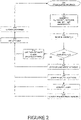
- New sensor measurements 200 are sent from the sensors 100 as sensor data 102 and received by the processor 114 . At least a subset of the sensor data 102 is used. All of the sensor data can be used, but may not be required, and not all of the sensor data has to be used.
- the mobile device 116 continuously takes sensor measurements along a mobile device path based on location and movement of the mobile device 116 .
- the processor 114 can run one or more low complexity modules (not shown in the figures) to extract essential data from the (raw, original, large amount of) sensor data 102 .
- This essential data is sent for further processing in the local processor 114 or optionally and preferably (via lazy upload 170 , connection 170B ) to the server 130 for optional server processing 160 .
- the server 130 can be implemented by a variety of techniques, including but not limited to a single machine, cluster of two or more computers, and cloud-based (computing).
- the extracted essential data can be used to generate and update a (unique) pedestrian lane map.
- essential data from multiple devices such as crowd-sourced data from a multitude of devices, is used to generate and update pedestrian lane maps.
- data from multiple uses (moving repeatedly over the same mobile device path) of one or a few devices can be used for processing.
- the processor 114 can also run one or more low complexity modules to position accurately the mobile device 116 on the most up-to-date local pedestrian lane map (area navigation map, discussed in more detail below). Note that a local pedestrian lane map can be received or retrieved by the mobile device 116 via the map download 128 as a lazy download or real time/on demand.
- the sensor data is used to generate 202 , a path estimate (path estimation, estimated path) and one or more unique path features (UPFs). Preferably, an inverse path is also generated.
- the local INS/PDR 104 typically also generates a location certainty (or the opposite, an uncertainty) measure and a global axis framework orientation estimate, which are used to align different mobile devices to the same axis framework. Preferably, the global axis framework orientation is independent of orientation of the mobile device 116 .
- Outputs of the INS/PDR 104 are generally referred to in the context of this document as "INS/PDR estimates" or "INS/PDR outputs".
- the local INS/PDR 104 generates a path estimate based on the sensor data.
- a path estimate is an estimation of a series of locations, at defined moments in time, along the movement path of the mobile device.
- a path estimate generally has at least two locations, typically at least several locations, and possibly a multitude of locations over a time period of at least a few seconds or over a path length measure corresponding to at least 1 meter.
- a section of a path, or a path segment is a partial cut from the multitude of location that maintains the locations order, for example all the locations between a path length corresponding to 3 to 15 meters, or 10 to 60 meters.
- a path estimate can also be thought of as a trajectory or trajectory estimate.
- one or more, typically at least several, of the following exemplary estimates can be measured and/or calculated from the incoming sensor data 102 : location, orientation/heading, magnetic field (typically calibrated magnetic field), and various RF estimates such as RSSI, PL, TDOA, and TOA.
- Magnetic field measurements are typically measured by the mobile device 116 magnetometer S03 .
- Calibrated magnetic field measurements can be generated by a calibration procedure performed to achieve a location measurements vector that is invariant to rotations, i.e. removing hard-iron and soft-iron effects from the measured magnetic field.
- Each group of one or more measurements (or estimates and calculated data) is known as a location measurement vector (LMV).
- Each estimate in the LMV may have a corresponding uncertainty/certainty measurement. For example, location and location uncertainty, orientation (which can be implemented in forms such as quaternion, rotation matrix, 2-direction vector in the global axis framework) and orientation uncertainty (to the global axis framework), and RSSI and RSSI uncertainty.
- Each type of estimate may have one or more values for each location, for example, an RSSI value from each of the received Wi-Fi hotspot signals in the area.
- RSSI and RSSI uncertainty may have one or more values for each location, for example, an RSSI value from each of the received Wi-Fi hotspot signals in the area.
- a typical implementation includes a path estimate including locations of the movement of the mobile device, and a location measurement vector including one or more measurements (or estimates) of one or more physical phenomenon at each location (in the path estimate).
- each LMV is associated with a different location and the locations corresponding to locations of the path estimate.
- the measured or estimated physical phenomenon is a static (or slowly varying) phenomenon that is similarly measured for a location by mobile devices. For example, consider calibrated magnetic field or RF estimates from multiple hotspots or Bluetooth low energy (BLE) beacons. The latter type of location measurement vector is also known in the literature as location fingerprint.
- An optional additional implementation includes defining a location measurement vector change (LMVC) for each group of measurements as some measure of change between two LMVs in a path taken by the mobile device.
- each measurement group does not include measurements at locations (points), but of the changes in measurements between two locations (two points in time).
- the selection of two points for a LMVC is not limited, nor is the measure of change. Typically, the two points are consecutive along the path of the mobile device and the operation is a difference operation.
- the measurements and estimates are associated as a function of growing time.
- the listed estimates and measures are for each point in time.
- the listed estimates and measures can be for each of some ("x") estimated distance traveled, or for each of some other ("y") estimated magnetic distance traveled (where magnetic distance is an amount of some accumulated magnetic change measure).
- x estimated distance traveled
- y estimated magnetic distance traveled
- magnetic distance is an amount of some accumulated magnetic change measure
- an additional assumption can be made that if the distance does not grow (fails to increase) then the estimates do not update (remain stable).
- the listed estimates and measures can be for each of some other (“z") estimated LMV distance traveled (where LMV distance traveled is an amount of some accumulated LMV change measure, i.e. absolute value on LMVC).
- the accumulated estimated distance traveled corresponds to an actual amount of distance traveled in the real world and can be used as a path length measure.
- the global axis framework orientation could be derived, for example, from a gravity estimate or a distance (or long time) smoothed magnetic estimate. Techniques are known in the art for generally generating a global axis framework orientation.
- the location certainty measure (or the location uncertainty) is a quantity referring to how accurate (or inaccurate) a measured or determined location is, as compared to the true (real-world) location.
- the local INS/PDR 104 preferably also generates an inverse path (or more technically, at this point in the processing, an inverse path estimate).
- An inverse path can be thought of as the mobile device moving backwards from the end to the beginning of a real mobile device path. In other words, if the user had walked the same path in the opposite direction.
- the inverse path can be generated, for example, by reversing the time order of sensor measurements for a given path length, or window of time over a length of a path estimate.
- Using gathered sensor data for a path to calculate an inverse path provides the system with additional data (for generating and updating pedestrian lane maps) without the need for a mobile device to actually collect data in two directions.
- an inverse path LMV and inverse LMVC can also be calculated,
- the local UPF module 106 generates one or more UPFs based on the sensor data 102 and the INS/PDR estimates from the local INS/PDR module 104 (such as path estimates, LMVs, and LMVC).
- the newly generated UPFs are associated with corresponding INS/PDR estimates from the same locations.
- the UPF association specifically includes the path estimate.
- a Unique Path Feature is an operation on location measurements (LMVs) and/or measurement changes (LMVCs) along the movement path of the mobile device.
- a UPF operation involves an operation on multiple measurements, typically all of the location measurements along a path (or section of a path/path section), for example an operation on a measurement vector or measurement change vector,
- a combination of UPF(s) and path estimate(s) uniquely identifies a path or a section of a path, in the indoor environment, hence the designator "UPF.”
- the operation is preferably robust to mobile device orientation, sensor noise, drift, bias, and interference.
- the operation is preferably invariant to the mobile device 116 orientation or global axis framework, i.e. two mobile devices taking the same path will produce a similar UPF no matter how the mobile device 116 is held by a user or the device initial axis framework, for example the dot product between two measured or estimated vector fields.
- the local UPF module 106 generates each UPF with a corresponding UPF certainty (or uncertainty), a quantity referring to how accurate (or inaccurate) a UPF is.
- the UPF uncertainty is derived from the measurements and estimates uncertainty on which the function generating the UPF is operating, and the operation.
- Examples of operations for generating a UPF include: Autocorrelation between the location measurement vectors and measurement changes over a path,
- the dot product can be used as multiplication, and when talking about radio signals measurements (for example, RSSI, PL, TDOA etc.), each element in the measurement vector is a measurement associated with a single beacon, hotspot or cellular base station.
- radio signals measurements for example, RSSI, PL, TDOA etc.
- a family of UPFs over magnetic measurements is referred to as magnetic UPFs.
- a family of UPFs over the known RF estimates such as RSSI, PL, and TDOA are referred to as RF UPFs.
- a feature of the current embodiment is that conventional use of measurements such as TDOA are for identifying a location, in contrast to the innovative use in the current embodiment of using measurements to (uniquely) identifying a path (line or series of points instead of a single point). For example, conventional RF fingerprinting measures RSSI at multiple points to pair each RSSI measurement with a location.
- a feature of the current embodiment is not (only) determining a location, but instead comparing a series of points to other series of points to determine a path (or a lane, as described in detail below).
- the current embodiment determines a UPF along a path length (a measure corresponding to the distance travelled by the sensored mobile device). This may be thought of as "path fingerprinting", as opposed to conventional "location fingerprinting”.
- An analogy can be made to hiking trails over a mountain: while each location on a trail has a certain height (fingerprint) the way the heights change over the trail (UPFs) creates a certain pattern or curve that uniquely identifies the trail amongst the nearby possible trails.
- the local INS/PDR module 104 outputs (including at least path estimates) and the local UPF module 106 newly generated UPFs are uploaded as data from the mobile device 116 (in general from multiple mobile devices / crowd-sourced as the lazy upload 170 via connection 170A ).
- a plurality of mobile devices 116 generates a plurality of respective UPFs for uploading.
- the uploaded data are then used by the AMGU module 120 (or the local data by the search and match module 108 ) to automatically generate and update one or more pedestrian lane maps with paths, junctions, and lanes, and associated unique features (UPFs).
- the AMGU module 120 essentially does a search for a match 204 between newly generated UPFs from multiple devices (or locally the search and match module 108 from the single mobile device 116 ) and known UPFs associated with already identified lanes (or sections of lanes, or concatenation of sections of lanes that intersect).
- An innovative feature of the current embodiment is searching and matching newly generated UPFs and associated path estimates, to a pedestrian lane map with known UPFs and associated lanes (or lane estimates).
- the method can perform various processing. If a match is not found (fails to find a match) then the path estimate associated with the (not found) UPFs is added to a map 220 (added to a pedestrian lane map) as a new lane estimate. The new lane estimate is added with the associated UPFs for that lane estimate (from the path estimate).
- An updated map 222 (pedestrian lane map) is generated and available (for example as update 126 to pedestrian lane map data 124 ) for storage, distribution, downloading, and retrieving (for example via map download 128 ) by mobile devices. In a case where processing is being done on the mobile device 116 by the search and match module 108 , the updated map 222 is immediately available to the processor 114 in place of, or in addition to the navigation map local copy 112 .
- Preparing includes optimizing the data and/or other known functions such as cleaning, sifting, and normalization.
- the path length can also be adjusted and/or optimized for matching sections of a path.
- the path estimates from one or more mobile devices 116 can be merged and smoothed based on matched sections (sections of the path estimates).
- Merging includes adding the newly generated UPFs and associated path estimate, to a pedestrian lane map with known UPFs and associated lanes (or lane estimates).
- This crowd-source technique converges to a unique navigation map (unique pedestrian lane map) where the paths that pedestrians take in an indoor environment are created with UPFs.
- this innovative technique models the way human walking behavior actually takes place in an indoor environment, simplifying way-finding significantly compared to conventional techniques.
- a preferred implementation of a pedestrian lane map is essentially as a directed multigraph.
- a multigraph is a graph that allows multiple directed edges (arrows) between vertices.
- a vertex in a multigraph can be used to represent a "junction" of a pedestrian lane map, and one of the edges connecting two vertices in a multigraph can be used to represent a "lane" of a pedestrian lane map.
- Each (directed) lane is associated with a set of path estimates and associated UPFs ordered from the source junction to the destination junction.
- a junction is mainly associated with a location estimate (and optionally a small amount of other path estimates).
- a "path split” has a temporary nature, that is, the system has not decided yet if a path split is a real junction or maybe a few users changing the lanes the users are taking. Path splits that are supported by additional data (path estimates and UPFs) continue to exist, can be verified, and eventually change status to being a junction.
- Identifying splits and junctions 210 is typically done any time new data is added to a pedestrian lane map.
- modules such as the prepare and merge 208 and the identify splits, and junctions 210 can update and have access to updated pedestrian lane maps (lines not shown on FIGURE 2 ).
- a probability of being a junction is increased for existing splits, and when the probability exceeds a designated probability the status of the split is changed to being a junction.
- One technique for identifying path splits is to increase the matched section lengths of path estimates being compared until the path estimates no longer match, i.e.
- either the UPFs or the INS/PDR path estimates start to differ strongly at the edges of matched sections.
- the points are first identified as path splits and added as vertices to the pedestrian lane map. If over time there are no additional splits in the vicinity of an original split, the vertex associated with the original split is discarded. If over time there are more splits in the vicinity of the original split then the split is recognized as a junction. The splits and junctions can be used to produce an updated map 222 .
- Identifying lanes 212 is also typically done any time new data is added to a pedestrian lane map. Similar to splits becoming junctions, path estimates are used to create lane estimates that may continue to exist, be verified, and eventually change status to being a "lane".
- a lane is a convergence of paths (represented by path estimates) from many different mobile devices. In simple terms, a lane can be thought of as the traffic pattern created where people walk with mobile devices. There can be more than one lane in a corridor (physical space where a mobile device moves).
- a lane has associated UPFs.
- the convergence of paths to a lane typically corresponds to whether or not the UPFs of the paths match (this process may also determine the lane width).
- Lane estimates can be a correlation tunnel of paths matched using UPFs and/or path estimates in close vicinity to one another with small enough (less than a given amount of) location uncertainty.
- correlated UPFs within a range, or a fitting between UPFs defines a boundary, a 3-dimensional (3D) tunnel (tunnel boundary). When two mobile devices travel within this tunnel boundary, each of the two mobile devices will produce UPFs that matches each other.
- the two path estimates might be considered as 'walking on the same lane'.
- a plurality of mobile devices 116 generates a plurality of respective UPFs
- a plurality of lanes can be calculated based on correlating the plurality of UPFs.
- Lanes connect splits and/or junctions. As described above, lanes are essentially edges with source and destination junctions being the same and in close proximity to one another. This identification of lanes allows the real time tracking to know when a user switches lanes. Lanes are consolidated and updated into a pedestrian navigation map. The lanes can be used to produce and/or update a pedestrian lane map, as shown as the updated map 222 .
- the method can identify environment changes 214 , such as removing non-verified or obsolete lanes and junctions.
- environment changes 214 such as removing non-verified or obsolete lanes and junctions.
- the lanes and junctions can be discarded.
- the given amount of time can be configured, and may vary from one location on a pedestrian lane map to another location on the map, or from one map to another map.
- a change in the measurement (fingerprint) environment will result in new additional lanes and junctions with associated new and additional UPFs. As such, obsolete lanes and junctions can be removed.
- Another way to discard existing lanes and junctions is when people (and corresponding mobile devices) move in close proximity to the existing lanes and junctions, but fail to get a measurement matching on the existing lanes and junctions.
- These techniques can clean out the pedestrian lane map as time progresses, making the map simpler to store and simpler to navigate on, as compared to a map retaining data that does not correlate (uncorrelated) with current lanes.
- the environment changes can be used to produce an updated map 222 .
- the method can update one or more geo-fences 224 .
- a geo-fence can be created and/or updated based on the new lanes.
- Geo-fences around lanes depict pedestrian movement areas and traffic islands, making the pedestrian lane map more complete, intuitive, and user-friendly when displayed to a user.
- a pedestrian lane map typically includes known UPFs and associated lanes (or lane estimates) as a basis of the map.
- Pedestrian lane maps can also include additional and optional data such as lane estimates, splits, paths, junctions, and associated navigation information (an information layer).
- FIGURE 3 a sketch of an AMGU example.
- the left side of the current figure diagrams a real (real-world) building map 340 and mobile device paths (also known as "ground truth"). Walls 300 , corridors 302 , and rooms 304 are shown. Three exemplary paths (mobile device paths) are shown: user1 path ( 1 ), user2 path ( 2 ), and user3 path (3) . Each exemplary path represents the movement of a user and the user's associated mobile device 116 .
- paths of users match, for example in a first section 306 both user1 path ( 1 ) and user2 path ( 2 ) travel the same corridor between a first intersection 308A and a second intersection 308B .
- both user1 and user3 move with associated mobile devices along the same corridor, but in different locations (sides of the corridor, where the paths of user1 and user3 do not match/fail to match).
- Each of user1 path ( 1 ) and user3 path ( 3 ) is shown on a side of the corridor for the same second section 310 .
- the right side of the current figure is a visual representation of a pedestrian lane map 342 .
- generation of the pedestrian lane map 342 is typically performed by the AMGU 120 on the server 130 .
- the pedestrian lane map 342 shows an exemplary lane 326 , a first junction 328A , a second junction 328B , and a path split 332 .
- sensor data 102 is collected from multiple mobile devices 116 as the mobile devices 116 move along a mobile device path (such as user1 path ( 1 ), user2 path ( 2 ), and user3 path ( 3 )).
- the AMGU module 120 does a search for a match 204 between newly received UPFs from multiple devices and known UPFs associated with already identified paths. For example, if exemplary lane 326 (and associated UPFs) is already known from previous processing of path estimates and UPFs from the user1 path (1) , then when path estimates and UPFs are received from user2 [user2's mobile device 114 moving along user2 path ( 2 )] user2's UPFs are compared to UPFs of the pedestrian lane map 342 . In this case, a match is found for user2's UPFs for the first section 306 .
- the data received from user2 is then used to identify and reinforce the mapping of lanes (exemplary lane 326 from first section 306 ), junctions (first junction 328A from first intersection 308A , and second junction 328B from second intersection 308B ), and identify or reinforce splits (for example split 332 ) as possible junctions.
- second section 310 (from building map 340 ) has been processed to identify two lanes in the second corridor 330 .
- One or more geo-fences 320 can be generated or updated to depict a skeleton of a floor plan around known lanes.
- FIGURE 4 a sketch of an AMGU map generation with drift of path estimates.
- the global coordinate system the global axis framework
- UPF matches can be found for the mobile devices to align one mobile coordinate system to another mobile coordinate system (for example, by gravity estimate, magnetic estimate, or other heading estimate).
- both the user1 path ( 1 ) and the user2 path ( 2 ) travel the same corridor between the first intersection 308A and the second intersection 308B .
- the two paths do not (fail to) estimate the exact same path - there is a drift, or a discrepancy between the real-world mobile devices paths estimates and coordinate systems
- the drift is an inherit property of the inertial sensors that results in generated data (path estimates) that is biased from the ground truth.
- the AMGU 120 processes the data from each of the user1 and user2 mobile devices, the AMGU must decide if the data is sufficiently close (within a predefined or determined range) to merge the data into a common lane estimate or lane.
- All of the user data can be stored in association with the identified exemplary lane 326 and used for future matching of user data to the pedestrian lane map 342 .
- the most up-to-date pedestrian lane map is maintained on the mobile device 116 as the navigation map local copy 112 .
- This pedestrian lane map is typically downloaded from the server 130 navigation map data 124 via the map download 128 to the mobile device 116 .
- the download can be via a lazy download when a connection is available, or requested by the mobile device in real-time when a navigation function (real-time positioning on the pedestrian lane map) is activated.
- a connection between the mobile device 116 and the server 130 is not available (unavailable)
- the mobile device can maintain and update the navigation map local copy 112 .
- the functions of generating UPFs and comparing the generated UPFs to stored UPFs are normally performed by the same processor 114 in the mobile device.
- the mobile device 116 processor 114 initiating one or more steps of the methods to be performed by other local or remote processors or devices.
- the sensor data 102 and/or the UPFs can be sent in real time (via connection 170A and/or connection 170B ) to server 130 for real-time processing and returning from the server 130 to the mobile device 116 pedestrian lane map, lanes, and/or location of the mobile device 116 (on one of the matching lanes).
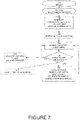
- FIGURE 7 a flowchart of a method for positioning (method for positioning and navigating using a pedestrian lane map), and also refer again to FIGURE 1 and FIGURE 2 .
- a method for positioning uses steps similar to the method for mapping.
- a method for positioning starts similar to the method for generating a map (mapping), by receiving 700 sensor data 102 based on location and movement of a mobile device 116 .
- the receiving 700 of sensor measurements for positioning is substantially the same as receiving new sensor measurements 200 when mapping.
- the local INS/PDR module 104 Based on at least a subset of the sensor data 102 , the local INS/PDR module 104 generates 702 a path estimate and a location measurement vector (LMV).
- the path estimate includes locations of the movement of the mobile device.
- the location measurement vector includes one or more measurements at each of the locations from the sensor data 102 from each of the locations.
- UPFs unique path features
- a feature of the current embodiment is that typically simultaneous localization and mapping (SLAM) is performed. Comparing mapping block 202 and navigating block 702 , both perform similar functions. When navigating, generation of path estimates, LMVs, and UPFs for navigating can also be used to generate new, and update existing pedestrian lane maps. One skilled in the field will see the connections and crossovers between the methods of mapping and positioning (navigating). For example, when navigating, block 702 can optionally generate an inverse path (similar to typical functioning of mapping block 202 ) for use in mapping during navigation.
- SLAM typically simultaneous localization and mapping
- determining 703 an initial rough location of the mobile device 116 to determine which sections on the pedestrian lane map are in the vicinity of the mobile device 116 can be done based on BLE beacons, Wi-Fi hotspots location data, inaccurate GPS readings and inaccurate INS/PDR estimates.
- a rough location estimate can also be given manually by human operation or by other external system such as camera barcode/QR scanning of known location tags. After an initial rough location is determined, the positioning method can be used to refine the location.
- a search for match is performed in block 704 , where the search and match module 108 performs a function similar to the AMGU module 120 including comparing the generated UPFs to stored UPFs in a pedestrian lane map (navigation map local copy 112 ) to determine matching UPFs. If (fails to find match) a match is not found 706 , the method loops to block 704 and continues searching for a match between the generated measurements and the pedestrian lane map.
- the non-matched outputs can be added to a map 220 (added to a pedestrian lane map) as a new lane estimate (and additional mapping functions continued as appropriate for SLAM).
- the output of the search and match module 108 can be used as feedback for correction 118 to the local INS/PDR module 104 .
- Feedback can include the generated UPFs, matched UPFs, matched location on one of the lanes, matched location map orientation/heading data and associated uncertainty measures. Feedback can be used to improve, subsequent generation of path estimates, heading, and orientation.
- the local INS/PDR module 104 can use the feedback for correction estimates and then output to the GUI 110 a location for presentation to a user of the mobile device 116 .
- the method When a match is found 706 , the method typically enters a tracking state 730 , or tracking mode. In this state, the location uncertainty is typically lower than the location uncertainty of a non-tracking state.
- the location uncertainty measure determines a search area, i.e. on which areas on the pedestrian lane map to search for a match. The uncertainty increases when no match is found, and decreases when a match is found. The tracking/non-tracking states can then be interpreted as significant decrease/increase in the location uncertainty measure.
- the geo-fence(s) can further improve real time location estimation by constraining the estimate not to cross a geo-fence (stay within the bounds of a geo-fence).
- Map data within the vicinity of the mobile device 116 can also be displayed, for example, to the GUI 100 on the mobile device 116 (connection not shown in figure).
- the matched outputs can be sent for identifying splits and junctions 210 (and additional mapping functions continued as appropriate for SLAM).
- Positioning, navigation, and tracking can include identifying when the mobile device 116 switches lanes, crosses junctions, stops, and lingers.
- the current device location can be used to find a route on the pedestrian lane map from the current device location, or other source location input, to another device location, or another destination location input and prepare the route's features for real time tracking.
- a route can be used in conjunction with one or more pedestrian lane maps to generate guiding instructions for navigation to a destination location based on the pedestrian lane map and the tracking of the mobile device 116 on the pedestrian lane map. For example, turn right in 5 meters, backup 10 meters etc.
- users or other systems can mark and add information to the pedestrian lane map, for example, locations of merchandise or items, advertisements, an information sign, etc.
- a visual representation of a pedestrian lane map 342 includes an overlay of user4 path ( 4 ) (dashed line) moving along the second corridor 330 , turning left at the first junction 328A into first section 306 until the second junction 328B , turning right.
- the user4 path estimate ( 4A ) varies from exemplary lane 326 .
- one dashed line shows the user4 path estimate ( 4A ) without correction feedback from the search and match module.
- the user's calculated UPFs matches the UPFs in the local pedestrian lane map, enabling a correction feedback from the search and match module 108 .
- a second dashed line ( 4B ) in the current figure shows the correction of the user4 path estimate ( 4B ) after this feedback from the search and match module.
- the innovative UPFs and pedestrian lane map enable functions such as route finding, generating guiding instructions, tracking, and analysis of pedestrian traffic.
- Finding a route on the pedestrian lane map from a first location (such as a current location of the mobile device and a location on the pedestrian lane map) to a second location (such as a location of a device other than the mobile device and a location on the pedestrian lane map) can be used to prepare features of the route for real-time tracking.
- Generating guiding instructions for navigation to a destination location can be done based on the pedestrian lane map. For example, instructions such as "turn right in 5 meters, backup 10 meters etc.”
- the mobile device can be tracked during navigation.
- the pedestrian lane map can be updated based on user-supplied information.
- users can add locations of stores, information signs, or adding advertisements.
- the pedestrian lane map and/or combinations of the location of the mobile device and user actions can be analyzed to generate analytics on pedestrian traffic behavior. For example, linger times/locations, busy hours, heatmaps - where people spent most time, and congestions.
- the local INS/PDR module 104 outputs a path estimate ⁇ ( t ) and (optionally) m B (t) magnetic measurements that can be fused with the gyroscope S02 data to have an orientation-independent axis framework (i.e. gyro rotates magnetic measurement to some initial body axis framework).
- An objective is to have the path estimate in the global axis framework orientation, but it is understood that without some initial GPS location or other means of side information this estimate may be highly inaccurate.
- INS/PDR suffers from an inherent drift due to general implementations using low cost sensors. For at least these reasons (see also below), location accuracy is also preferably estimated ⁇ ⁇ ( t ) and assumed to grow over time without location correction.
- the inputs to the local INS/PDR module 104 include sensor data 102 from sensors 100 such as accelerometer S01 , gyroscope S02 , magnetometer S03 , barometer S04 /altimeter, and GPS receiver S06.
- INS/PDR algorithms are known in the art, for example see Pedestrian dead reckoning for MARG navigation using a smartphone, by Z Tian, Y Zhang, M Zhou, and Y Liu, EURASIP Journal on Advances in Signal Processing 2014 (1), 1-9 .
- the inputs to the local UPF module 106 include ⁇ ( t ) from the local INS/PDR module 104 and m ( t ) - the raw magnetic measurement signals of some in-building paths from the smartphone magnetometer (and optionally m B ( t ))
- path length parameterization instead of time parameterization of the path, path length parameterization will be used here:
- the path length is calculated from the path estimate of the local INS/PDR module 104 , i.e. and also used to find a matching window size in the below description.
- Examples of other path functions, to generate other distinctive path features, include: and similar, each functions having physical world pros and cons.
- ⁇ 1,2 ( l ) are fingerprint (measurement) vectors of measurement with corresponding size at a specific location.
- this is basically generating the autocorrelation of the path of vector measurements along a path.
- a variant of this is taking a cyclic autocorrelation of a path length L in order to limit the location measurements into path sections.
- the measurement path length can be used, however this may more prone to location measurements noise.
- T is an RF measurements vector where each element is associated with a fixed infrastructure point, i.e. cellular cell id or Wi-Fi hotspot MAC ID, and the elements arc measurements such as RSSI, path loss (PL), and TDOA.
- the UPFs can be high pass filtered to remove the long-term average.
- An alternative approach to calculating the UPF can be to directly take the dot product as the UPF and construct the integral and DC removal as part of the AMGU search and match procedures.
- the norm is some p-norm if considering the auto-correlation for the UPFs or L p -norm when considering only the dot product as UPF.
- the actual pedestrian lane map is a directed multigraph so there are actually several options of building F r map for each location in the pedestrian lane map (referred to by r ).
- the minimal value e L ( l , r ) can be taken over the options.
- F r map was search limited to within reasonable search bounds of the location uncertainty, i.e. ⁇ r :
- a decision device (with thresholds) can be derived since when there is a long path match and when not .
- L min and L max are predefined parameters.
- MRC Maximal Ratio Combining
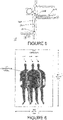
- FIGURE 6 a sketch of a correlation tunnel in a typical office space.
- lane estimates can he a correlation tunnel of paths matched using UPFs and/or path estimates in close vicinity to one another with small enough (less than a given amount of) location uncertainty.
- a typical office corridor 600 may have a width 602 of 2 meters (2 m) and a height 604 of 3 meters (3 m).
- a correlation tunnel 606 can be formed by the movement of one or more users (corresponding to the user(s)' associated mobile device(s) 116 ) in differing positions in the corridor 600 , such as the middle of the corridor 611 , left of middle 612 or right of middle 613 .
- the exemplary correlation tunnel is 0.9 m in height and 0.5 m in width, centered on the calculated path.
- the correlation tunnel may represent different positions of users as the users travel through the corridor and/or the different positions of the user's associated mobile device 116 .
- the user's mobile device 116 may be lower on the user (worn on the hip, held in hand), in the middle of the user (in a shirt or jacket breast pocket), or higher on the user (near the head while talking on the phone).
- ⁇ e 2 should not exceed 0.25 meters).
- an averaging function can be used with a forgetting factor so the pedestrian lane map has a forgetting factor and can adapt to environmental changes.
- FIGURE 8 is a high-level partial block diagram of an exemplary system 900 configured to implement the system of the present invention.
- the system 900 can be used to implement one or more components and/or modules such as the processor 114 , server 130 , and optional server processing 160 .
- System (processing system) 900 includes a processor 902 (one or more) and four exemplary memory devices: a RAM 904 , a boot ROM 906 , a mass storage device (hard disk) 908 , and a flash memory 910 , all communicating via a common bus 912 .
- processing and memory can include any computer readable medium storing software and/or firmware and/or any hardware element(s) including but not limited to field programmable logic array (FPLA) element(s), hard-wired logic element(s), field programmable gate array (FPGA) element(s), and application-specific integrated circuit (ASIC) element(s).
- FPLA field programmable logic array
- FPGA field programmable gate array
- ASIC application-specific integrated circuit
- Any instruction set architecture may be used in processor 902 including but not limited to reduced instruction set computer (RISC) architecture and/or complex instruction set computer (CISC) architecture.
- a module (processing module) 914 is shown on mass storage 908 , but as will be obvious to one skilled in the art, could be located on any of the memory devices.
- Mass storage device 908 is a non-limiting example of a non-transitory computer-readable storage medium bearing computer-readable code for implementing the mapping, tracking, positioning, and navigating methodology described herein.
- Other examples of such computer-readable storage media include read-only memories such as CDs bearing such code.
- System 900 may have an operating system stored on the memory devices, the ROM may include boot code for the system, and the processor may be configured for executing the boot code to load the operating system to RAM 904 , executing the operating system to copy computer-readable code to RAM 904 and execute the code.
- Network connection 620 provides communications to and from system 900 .
- a single network connection provides one or more links, including virtual connections, to other devices on local and/or remote networks.
- system 900 can include more than one network connection (not shown), each network connection providing one or more links to other devices and/or networks.
- System 900 can be implemented as a server or client respectively connected through a network to a client or server.
- Modules are preferably implemented in software, but can also be implemented in hardware and firmware, on a single processor or distributed processors, at one or more locations.
- the above-described module functions can be combined and implemented as fewer modules or separated into sub-functions and implemented as a larger number of modules. Based on the above description, one skilled in the art will be able to design an implementation for a specific application.
Landscapes
- Engineering & Computer Science (AREA)
- Remote Sensing (AREA)
- Radar, Positioning & Navigation (AREA)
- Physics & Mathematics (AREA)
- General Physics & Mathematics (AREA)
- Automation & Control Theory (AREA)
- Computer Networks & Wireless Communication (AREA)
- Signal Processing (AREA)
- Electromagnetism (AREA)
- Navigation (AREA)
- Position Fixing By Use Of Radio Waves (AREA)
Claims (13)
- Verfahren zum Kartografieren, das die folgenden Schritte umfasst:(a) Empfangen (200) von Sensordaten (102) basierend auf einem Ort und einem Bewegungspfad einer Mobilvorrichtung (116);(b) Erzeugen (202), basierend auf den Sensordaten (102), eines Pfadschätzvektors und eines Ortsmessvektors,(i) wobei der Pfadschätzvektor Orte der Bewegung der Mobilvorrichtung (116) beinhaltet; und(ii) wobei der Ortsmessvektor auf magnetischem Feld und/oder Hochfrequenz-Beacon basierende Messungen an jedem der Orte von den Sensordaten (102) von jedem der Orte beinhaltet; und(c) Erzeugen (202) eines oder mehrerer eindeutiger Pfadmerkmale (unique path features - UPFs), wobei die UPFs den Pfad charakterisieren,dadurch gekennzeichnet, dass die UPFs erzeugt werden,durch Durchführen eines Ablaufs über den Bewegungspfad,wobei der Ablauf auf dem Pfadschätzungsvektor und dem Ortsmessvektor basiert.
- Verfahren nach Anspruch 1, das ferner die folgenden Schritte beinhaltet:(d) Vergleichen der erzeugten UPFs mit gespeicherten UPFs in einer Fußgängerwegkarte, um übereinstimmende UPFs zu bestimmen.
- Verfahren nach Anspruch 1, das ferner den folgenden Schritt beinhaltet: Berechnen, basierend auf den UPFs, eines oder mehrerer Fußgängerwege, entlang denen sich die Mobilvorrichtung (116) bewegt hat.
- Verfahren nach Anspruch 1, das ferner einen Schritt des Berechnens einer oder mehrerer Wegschätzungen basierend auf den UPFs, und dann des Berechnens einer Konvergenz der Wegschätzungen in einen oder mehrere Fußgängerwege, umfasst.
- Verfahren nach Anspruch 1, wobei mehrere UPFs aus einer Gruppe ausgewählt sind, die aus Folgendem besteht:(a) jeweils für entsprechende mehrere Mobilvorrichtungen (116) erzeugte, und(b) aus entsprechenden mehreren Mobilvorrichtungen (116) durch Schwarmauslagerung erhaltene.
- Verfahren nach Anspruch 1, das ferner den folgenden Schritt beinhaltet: Erzeugen eines Umkehrpfads basierend auf einem Umkehren der Sensordaten (102).
- Verfahren nach Anspruch 2, wobei die übereinstimmenden UPFs zugeordnete Fußgängerwege aufweisen.
- Verfahren nach Anspruch 7, das ferner den Folgenden Schritt umfasst: Berechnen, basierend auf den Sensordaten (102) und den Fußgängerwegen, eines Orts auf einem der Fußgängerwege der Mobilvorrichtung (116).
- Verfahren nach Anspruch 2, das eine oder mehrere Funktionen beinhaltet, die aus der Gruppe ausgewählt sind, die aus Folgendem besteht:(a) Finden einer Route auf der Fußgängerwegkarte von einem ersten Ort, der aus der Gruppe ausgewählt ist, die aus Folgendem besteht:(i) einem aktuellen Ort der Mobilvorrichtung (116); und(ii) einem Ort auf der Fußgängerwegkarte,
zu einem zweiten Ort, der aus der Gruppe ausgewählt ist, die aus Folgendem besteht:(iii) einem Ort einer anderen Vorrichtung als der Mobilvorrichtung (116); und(iv) einem Ort auf der Fußgängerwegkarte;
und Vorbereiten von Merkmalen der Route für ein Echtzeitverfolgen.(b) Erzeugen von Führungsanweisungen für eine Navigation zu einem Zielort basierend auf der Fußgängerwegkarte;(c) Verfolgen der Mobilvorrichtung (116) während der Navigation;(d) Aktualisieren der Fußgängerwegkarte basierend auf von einem Benutzer bereitgestellten Informationen;(e) Analysieren der Fußgängerwegkarte, um Analysen von
Fußgängerverkehrsverhalten zu erzeugen;(f) Analysieren von Kombinationen des Orts der Mobilvorrichtung (116) und Benutzeraktionen; und(g) Bereitstellen von Fußgängerwegen von den übereinstimmenden UPFs an eine Kartenanzeige. - Verfahren nach Anspruch 1, wobei(a) ein Pfadlängenmaß basierend auf den Sensordaten (102) erzeugt wird, und(b) die UPFs auf einer Pfadlänge erzeugt werden, die dem Pfadlängenmaß entspricht.
- Verfahren nach Anspruch 10, wobei
wobei das Pfadlängenmaß aus der Gruppe ausgewählt ist, die aus Folgendem besteht:(i) geschätzter zurückgelegter Entfernung,(ii) geschätzter zurückgelegter magnetischer Entfernung, und(iii) geschätzter zurückgelegter Entfernung des Ortsmessvektors. - Verfahren nach Anspruch 1, wobei der Ortsmessvektor eine oder mehrere Messungen beinhaltet, die aus der Gruppe ausgewählt sind, die aus Folgendem besteht:(a) Messungen des magnetischen Felds;(b) kalibrierten Messungen des magnetischen Felds;(c) Funksignalstärkekennzeichen (radio signal strength indicator - RSSI),
Messen von Wi-Fi, Bluetooth-Niedrigenergie (Bluetooth low energy - BLE), einer zellularer Basisstation und/oder anderen Hochfrequenz(HF)-Beacons;(d) Pfadverlust(path loss - PL)-Messungen von Wi-Fi, BLE, der zellularen Basisstation und/oder anderen HF-Beacons;(e) Ankuftszeitdifferenz(time difference of arrival - TDOA)-Messungen von Wi-Fi-, BLE, der zellularen Basisstation und/oder anderen HF-Beacons und(f) basierend auf einer Änderung von einem ersten der Orte zu einem anderen der Orte. - Verfahren nach Anspruch 1, wobei der Ablauf eine oder mehrere Techniken sind, die aus der Gruppe ausgewählt sind, die aus Folgendem besteht:(a) einem Punktprodukt zwischen dem Ortsmessvektor und Messänderungen;(b) Autokorrelation;(c) Kreuzkorrelation;(d) einem Pfadintegral über dem Pfadschätzvektor;(e) Autokorrelation zwischen dem Ortsmessvektor und Messänderungen über dem Pfadschätzvektor;(f) einem Pfadintegral von magnetischen Messungen über dem Ortsmessvektor;(g) einem Pfadintegral von magnetischen Messungen über einer Pfadänderungsschätzung;(h) einem Pfadintegral von magnetischen Messungen über Änderungen von magnetischen Messungen;(i) einer Funktion von RSSI;(j) einer Funktion von RSSI über dem Ortsmessvektor;(k) einem Pfadintegral von RSSI-Messungen über Änderungen von RSSI-Messungen;(l) einer Funktion des Pfadverlusts über dem Ortsmessvektor;(m) einem Pfadintegral von PL-Messungen über Änderungen von PL-Messungen;(n) einer Funktion von TDOA über dem Ortsmessvektor;(o) einem Pfadintegral von TDOA-Messungen über Änderungen von TDOA-Messungen; oder wobei der Ablauf Folgendes ist:
eine ausrichtungsinvariante Funktion, unabhängig von der Ausrichtung der Mobilvorrichtung.
Applications Claiming Priority (2)
| Application Number | Priority Date | Filing Date | Title |
|---|---|---|---|
| US201562216575P | 2015-09-10 | 2015-09-10 | |
| PCT/IB2016/055233 WO2017042672A1 (en) | 2015-09-10 | 2016-09-01 | Navigate, track, and position mobile devices in gps-denied or gps-inaccurate areas with automatic map generation |
Publications (3)
| Publication Number | Publication Date |
|---|---|
| EP3347677A1 EP3347677A1 (de) | 2018-07-18 |
| EP3347677A4 EP3347677A4 (de) | 2019-01-02 |
| EP3347677B1 true EP3347677B1 (de) | 2022-04-06 |
Family
ID=58239222
Family Applications (1)
| Application Number | Title | Priority Date | Filing Date |
|---|---|---|---|
| EP16843762.2A Active EP3347677B1 (de) | 2015-09-10 | 2016-09-01 | Navigation, verfolgung und positionierung mobiler vorrichtungen in gps-verweigerten oder gps-ungenauen bereichen mit automatischer kartenerstellung |
Country Status (7)
| Country | Link |
|---|---|
| US (2) | US10584972B2 (de) |
| EP (1) | EP3347677B1 (de) |
| KR (1) | KR20180052636A (de) |
| CN (1) | CN108351217B (de) |
| ES (1) | ES2920837T3 (de) |
| IL (1) | IL257725B (de) |
| WO (1) | WO2017042672A1 (de) |
Families Citing this family (54)
| Publication number | Priority date | Publication date | Assignee | Title |
|---|---|---|---|---|
| CN108351217B (zh) * | 2015-09-10 | 2022-03-01 | 欧里伊恩特新媒体有限公司 | 在全球定位系统拒绝访问的导航、追踪及定位的移动装置 |
| KR102500299B1 (ko) * | 2015-12-03 | 2023-02-16 | 삼성전자주식회사 | 사용자 단말 및 그 제어 방법 |
| US10151588B1 (en) | 2016-09-28 | 2018-12-11 | Near Earth Autonomy, Inc. | Determining position and orientation for aerial vehicle in GNSS-denied situations |
| US20190104492A1 (en) * | 2017-03-28 | 2019-04-04 | Irvine Sensors Corporation | Cell Phone-Based Land Navigation Methods and Systems |
| US12094614B2 (en) | 2017-08-15 | 2024-09-17 | Koko Home, Inc. | Radar apparatus with natural convection |
| US10830592B2 (en) * | 2017-09-21 | 2020-11-10 | Dell Products L.P. | Indoor navigation path determination system |
| JP6740988B2 (ja) * | 2017-09-26 | 2020-08-19 | カシオ計算機株式会社 | 地図情報提供装置、携帯型地図送信装置、地図情報提供システム、地図情報提供方法及びプログラム |
| CN107632606A (zh) * | 2017-09-27 | 2018-01-26 | 哈工大机器人(合肥)国际创新研究院 | 大区域基于Slam和Tag标签的移动机器人导航与定位方法 |
| EP3837674A4 (de) | 2018-08-13 | 2022-05-18 | Magic Leap, Inc. | Realitätsübergreifendes system |
| US11227435B2 (en) | 2018-08-13 | 2022-01-18 | Magic Leap, Inc. | Cross reality system |
| US11232635B2 (en) | 2018-10-05 | 2022-01-25 | Magic Leap, Inc. | Rendering location specific virtual content in any location |
| EP3782381B1 (de) * | 2018-12-17 | 2024-03-06 | Google LLC | Entdeckung und reihung von standorten zur verwendung durch geografische kontextanwendungen |
| US11997455B2 (en) | 2019-02-11 | 2024-05-28 | Koko Home, Inc. | System and method for processing multi-directional signals and feedback to a user to improve sleep |
| US11971503B2 (en) | 2019-02-19 | 2024-04-30 | Koko Home, Inc. | System and method for determining user activities using multiple sources |
| WO2020218630A1 (ko) * | 2019-04-22 | 2020-10-29 | 엘지전자 주식회사 | 안내 로봇의 다중 정보 제공 시스템 및 그 방법 |
| IL266185B (en) | 2019-04-23 | 2022-07-01 | Oriient New Media Ltd | Indoor positioning paths mapping tool |
| US10775175B1 (en) * | 2019-06-28 | 2020-09-15 | Rockwell Collins, Inc. | Wearable dead reckoning system for GPS-denied navigation |
| US10616723B1 (en) * | 2019-07-16 | 2020-04-07 | Eagle Technology, Llc | System for mapping building interior with PDR and ranging and related methods |
| JP7274970B2 (ja) * | 2019-08-01 | 2023-05-17 | 本田技研工業株式会社 | 追従対象特定システム及び追従対象特定方法 |
| CN110519701B (zh) * | 2019-08-15 | 2021-02-12 | 广州小鹏汽车科技有限公司 | 定位信息的创建方法、车载终端、服务器设备和定位系统 |
| EP4046139A4 (de) | 2019-10-15 | 2023-11-22 | Magic Leap, Inc. | Realitätsübergreifendes system mit lokalisierungsdienst |
| EP4046070A4 (de) | 2019-10-15 | 2023-10-18 | Magic Leap, Inc. | Realitätsübergreifendes system, das mehrere gerätetypen unterstützt |
| US11632679B2 (en) | 2019-10-15 | 2023-04-18 | Magic Leap, Inc. | Cross reality system with wireless fingerprints |
| KR102814112B1 (ko) * | 2019-10-25 | 2025-05-29 | 삼성전자주식회사 | 위치를 탐지하는 전자 장치 및 그 방법 |
| WO2021087065A1 (en) | 2019-10-31 | 2021-05-06 | Magic Leap, Inc. | Cross reality system with quality information about persistent coordinate frames |
| CN114730546B (zh) | 2019-11-12 | 2025-05-30 | 奇跃公司 | 具有定位服务和基于位置的共享内容的交叉现实系统 |
| KR20210058604A (ko) | 2019-11-14 | 2021-05-24 | 김성우 | 이동식 초음파세척기 |
| EP4073763A4 (de) | 2019-12-09 | 2023-12-27 | Magic Leap, Inc. | Realitätsübergreifendes system mit vereinfachter programmierung von virtuellen inhalten |
| US11410395B2 (en) | 2020-02-13 | 2022-08-09 | Magic Leap, Inc. | Cross reality system with accurate shared maps |
| CN115398484A (zh) | 2020-02-13 | 2022-11-25 | 奇跃公司 | 具有用于定位的地理定位信息优先级的交叉现实系统 |
| WO2021163300A1 (en) | 2020-02-13 | 2021-08-19 | Magic Leap, Inc. | Cross reality system with map processing using multi-resolution frame descriptors |
| US11551430B2 (en) | 2020-02-26 | 2023-01-10 | Magic Leap, Inc. | Cross reality system with fast localization |
| US11668572B2 (en) * | 2020-03-04 | 2023-06-06 | Johnson Controls Tyco IP Holdings LLP | Systems and methods for generating indoor paths |
| US20230124127A1 (en) * | 2020-03-13 | 2023-04-20 | Lg Electronics Inc. | Method for predicting entry path by vru device in wireless communication system supporting sidelink, and apparatus therefor |
| WO2021182934A1 (ko) * | 2020-03-13 | 2021-09-16 | 엘지전자 주식회사 | 사이드링크를 지원하는 무선통신시스템에서 vru가 이동 경로를 예측하는 방법 및 이를 위한 장치 |
| US11240635B1 (en) * | 2020-04-03 | 2022-02-01 | Koko Home, Inc. | System and method for processing using multi-core processors, signals, and AI processors from multiple sources to create a spatial map of selected region |
| US12000707B2 (en) | 2020-04-28 | 2024-06-04 | Grabtaxi Holdings Pte. Ltd. | Communications server apparatus and methods of operation thereof |
| US11900547B2 (en) | 2020-04-29 | 2024-02-13 | Magic Leap, Inc. | Cross reality system for large scale environments |
| CN111486849B (zh) * | 2020-05-29 | 2021-08-27 | 北京大学 | 一种基于二维码路标的移动视觉导航方法及系统 |
| US20210396522A1 (en) * | 2020-06-17 | 2021-12-23 | Microsoft Technology Licensing, Llc | Pedestrian dead reckoning using map constraining features |
| US20210396542A1 (en) * | 2020-06-17 | 2021-12-23 | Astra Navigation, Inc. | Operating Modes of Magnetic Navigation Devices |
| US11703335B2 (en) * | 2020-06-19 | 2023-07-18 | Toyota Research Institute, Inc. | Coordinating and learning maps dynamically |
| US11546724B2 (en) | 2020-08-12 | 2023-01-03 | Here Global B.V. | Method, apparatus, and system for determining a non-specific location according to an observed mobility pattern derived from non-positioning related sensor data |
| US11681304B2 (en) | 2020-09-01 | 2023-06-20 | International Business Machines Corporation | Emergency response system |
| US11592517B2 (en) * | 2020-12-19 | 2023-02-28 | Here Global B.V. | Offline radio maps for GNSS-denied areas |
| US11617059B1 (en) | 2021-05-28 | 2023-03-28 | T-Mobile Usa, Inc. | Mobile device geographic location determination for emergency services |
| US12498245B2 (en) * | 2021-06-14 | 2025-12-16 | Astra Navigation, Inc. | Embedding a magnetic map into an image file |
| CN113573232B (zh) * | 2021-07-13 | 2024-04-19 | 深圳优地科技有限公司 | 机器人巷道定位方法、装置、设备及存储介质 |
| US20250130071A1 (en) * | 2021-09-17 | 2025-04-24 | Hid Global Corp. | Location recognition using inertial measurement unit |
| US20240078804A1 (en) * | 2022-09-06 | 2024-03-07 | Ssct Llc | Geographic land optimization system and method |
| US20240192018A1 (en) * | 2022-12-07 | 2024-06-13 | Here Global B.V. | System and method for virtual lane generation |
| US20250056235A1 (en) * | 2023-08-08 | 2025-02-13 | Astra Navigation, Inc. | Authenticating a Device Using Geofencing Data |
| US20250251483A1 (en) * | 2024-02-01 | 2025-08-07 | Cisco Technology, Inc. | Resource-efficient wireless ranging and localization techniques |
| CN118049995B (zh) * | 2024-04-16 | 2024-07-05 | 暨南大学 | 一种基于卫惯组合技术的船载智能导航方法 |
Family Cites Families (10)
| Publication number | Priority date | Publication date | Assignee | Title |
|---|---|---|---|---|
| US7538715B2 (en) * | 2004-10-04 | 2009-05-26 | Q-Track Corporation | Electromagnetic location and display system and method |
| US9395190B1 (en) | 2007-05-31 | 2016-07-19 | Trx Systems, Inc. | Crowd sourced mapping with robust structural features |
| US8751151B2 (en) * | 2012-06-12 | 2014-06-10 | Trx Systems, Inc. | System and method for localizing a trackee at a location and mapping the location using inertial sensor information |
| TWI408340B (zh) * | 2009-07-27 | 2013-09-11 | Htc Corp | 導航路徑顯示方法、導航裝置及電腦程式產品 |
| EP2620750B1 (de) * | 2012-01-26 | 2024-11-06 | Hyundai Motor Company | Vorrichtung und Verfahren zur Erzeugung eines Pfads |
| US9297658B2 (en) * | 2012-06-12 | 2016-03-29 | Trx Systems, Inc. | Wi-Fi enhanced tracking algorithms |
| US9226111B2 (en) * | 2012-11-21 | 2015-12-29 | Apple Inc. | Pathway matching |
| US9250080B2 (en) * | 2014-01-16 | 2016-02-02 | Qualcomm Incorporated | Sensor assisted validation and usage of map information as navigation measurements |
| US10281282B2 (en) * | 2014-02-17 | 2019-05-07 | Oxford University Innovation Limited | Determining the position of a mobile device in a geographical area |
| CN108351217B (zh) * | 2015-09-10 | 2022-03-01 | 欧里伊恩特新媒体有限公司 | 在全球定位系统拒绝访问的导航、追踪及定位的移动装置 |
-
2016
- 2016-09-01 CN CN201680052131.1A patent/CN108351217B/zh active Active
- 2016-09-01 EP EP16843762.2A patent/EP3347677B1/de active Active
- 2016-09-01 WO PCT/IB2016/055233 patent/WO2017042672A1/en not_active Ceased
- 2016-09-01 US US15/757,656 patent/US10584972B2/en active Active
- 2016-09-01 ES ES16843762T patent/ES2920837T3/es active Active
- 2016-09-01 KR KR1020187007363A patent/KR20180052636A/ko not_active Ceased
-
2018
- 2018-02-25 IL IL257725A patent/IL257725B/en unknown
-
2020
- 2020-01-06 US US16/734,861 patent/US11187540B2/en active Active
Non-Patent Citations (1)
| Title |
|---|
| None * |
Also Published As
| Publication number | Publication date |
|---|---|
| ES2920837T3 (es) | 2022-08-10 |
| WO2017042672A1 (en) | 2017-03-16 |
| US20200141739A1 (en) | 2020-05-07 |
| US10584972B2 (en) | 2020-03-10 |
| CN108351217A (zh) | 2018-07-31 |
| CN108351217B (zh) | 2022-03-01 |
| EP3347677A1 (de) | 2018-07-18 |
| EP3347677A4 (de) | 2019-01-02 |
| IL257725B (en) | 2021-08-31 |
| IL257725A (en) | 2018-04-30 |
| US20180245927A1 (en) | 2018-08-30 |
| US11187540B2 (en) | 2021-11-30 |
| KR20180052636A (ko) | 2018-05-18 |
Similar Documents
| Publication | Publication Date | Title |
|---|---|---|
| US11187540B2 (en) | Navigate, track, and position mobile devices in GPS-denied or GPS-inaccurate areas with automatic map generation | |
| EP3351024B1 (de) | Bestimmung des standortes von referenzmarkern | |
| KR101904214B1 (ko) | 실내 위치 측정 방법 및 장치 | |
| CN104390643B (zh) | 基于多信息融合实现室内定位的方法 | |
| US10356562B2 (en) | Systems and methods for graph-based localization and mapping | |
| WO2018184108A1 (en) | Location-based services system and method therefor | |
| US20140180576A1 (en) | Estimation of time of arrival based upon ambient identifiable wireless signal sources encountered along a route | |
| CN106441302B (zh) | 大型开放式区域内的室内定位方法 | |
| CN105044668A (zh) | 一种基于多传感器装置的wifi指纹数据库构建方法 | |
| CN110501010A (zh) | 确定移动设备在地理区域中的位置 | |
| EP3881031B1 (de) | Systeme und verfahren zur richtungsschätzung an innen- und aussenorten | |
| WO2014051755A1 (en) | Route learning with networked assistance | |
| Liu et al. | A low-cost and scalable framework to build large-scale localization benchmark for augmented reality | |
| WO2025037291A2 (en) | Enhancement of the 3d indoor positioning by augmenting a multitude of 3d imaging, lidar distance corrections, imu sensors and 3-d ultrasound | |
| KR101947442B1 (ko) | 서로 다른 측위 자원들의 결합을 이용한 위치 추정 장치 및 방법 | |
| KR20160105628A (ko) | 비콘과 가속도 센서를 활용한 이동거리와 위치 측정 방법 및 이를 이용한 실내 측위 시스템 | |
| Chow et al. | Indoor tracking, mapping, and navigation: algorithms, technologies, and applications | |
| CN110967013A (zh) | 一种基于室内地磁场信息和智能手机的室内区域定位系统 | |
| Ebner et al. | On prior navigation knowledge in multi sensor indoor localisation | |
| Ghantous et al. | Augmented reality indoor navigation based on Wi-Fi trilateration | |
| Kessel et al. | Automated WLAN calibration with a backtracking particle filter | |
| Diallo et al. | Decentralized collaborative inertial tracking | |
| JP2017026542A (ja) | 位置推定装置、位置推定方法および位置推定プログラム | |
| Wu et al. | Hybrid location estimation by fusing WLAN signals and inertial data | |
| Li et al. | A Graph Optimization Enhanced Indoor Localization Method |
Legal Events
| Date | Code | Title | Description |
|---|---|---|---|
| STAA | Information on the status of an ep patent application or granted ep patent |
Free format text: STATUS: THE INTERNATIONAL PUBLICATION HAS BEEN MADE |
|
| PUAI | Public reference made under article 153(3) epc to a published international application that has entered the european phase |
Free format text: ORIGINAL CODE: 0009012 |
|
| STAA | Information on the status of an ep patent application or granted ep patent |
Free format text: STATUS: REQUEST FOR EXAMINATION WAS MADE |
|
| 17P | Request for examination filed |
Effective date: 20180327 |
|
| AK | Designated contracting states |
Kind code of ref document: A1 Designated state(s): AL AT BE BG CH CY CZ DE DK EE ES FI FR GB GR HR HU IE IS IT LI LT LU LV MC MK MT NL NO PL PT RO RS SE SI SK SM TR |
|
| AX | Request for extension of the european patent |
Extension state: BA ME |
|
| RIC1 | Information provided on ipc code assigned before grant |
Ipc: G01C 21/20 20060101ALI20180813BHEP Ipc: G01C 21/16 20060101ALI20180813BHEP Ipc: G01C 21/32 20060101AFI20180813BHEP |
|
| DAV | Request for validation of the european patent (deleted) | ||
| DAX | Request for extension of the european patent (deleted) | ||
| A4 | Supplementary search report drawn up and despatched |
Effective date: 20181203 |
|
| RIC1 | Information provided on ipc code assigned before grant |
Ipc: G01C 21/20 20060101ALI20181127BHEP Ipc: G01C 21/16 20060101ALI20181127BHEP Ipc: G01C 21/32 20060101AFI20181127BHEP |
|
| STAA | Information on the status of an ep patent application or granted ep patent |
Free format text: STATUS: EXAMINATION IS IN PROGRESS |
|
| 17Q | First examination report despatched |
Effective date: 20191002 |
|
| GRAP | Despatch of communication of intention to grant a patent |
Free format text: ORIGINAL CODE: EPIDOSNIGR1 |
|
| STAA | Information on the status of an ep patent application or granted ep patent |
Free format text: STATUS: GRANT OF PATENT IS INTENDED |
|
| RIC1 | Information provided on ipc code assigned before grant |
Ipc: H04W 4/02 20180101ALI20210910BHEP Ipc: G01C 21/20 20060101ALI20210910BHEP Ipc: G01C 21/16 20060101ALI20210910BHEP Ipc: G01C 21/32 20060101AFI20210910BHEP |
|
| INTG | Intention to grant announced |
Effective date: 20211020 |
|
| GRAS | Grant fee paid |
Free format text: ORIGINAL CODE: EPIDOSNIGR3 |
|
| GRAA | (expected) grant |
Free format text: ORIGINAL CODE: 0009210 |
|
| STAA | Information on the status of an ep patent application or granted ep patent |
Free format text: STATUS: THE PATENT HAS BEEN GRANTED |
|
| AK | Designated contracting states |
Kind code of ref document: B1 Designated state(s): AL AT BE BG CH CY CZ DE DK EE ES FI FR GB GR HR HU IE IS IT LI LT LU LV MC MK MT NL NO PL PT RO RS SE SI SK SM TR |
|
| REG | Reference to a national code |
Ref country code: GB Ref legal event code: FG4D |
|
| REG | Reference to a national code |
Ref country code: CH Ref legal event code: EP |
|
| REG | Reference to a national code |
Ref country code: AT Ref legal event code: REF Ref document number: 1481738 Country of ref document: AT Kind code of ref document: T Effective date: 20220415 |
|
| REG | Reference to a national code |
Ref country code: DE Ref legal event code: R096 Ref document number: 602016070887 Country of ref document: DE |
|
| REG | Reference to a national code |
Ref country code: IE Ref legal event code: FG4D |
|
| REG | Reference to a national code |
Ref country code: FI Ref legal event code: FGE |
|
| REG | Reference to a national code |
Ref country code: NL Ref legal event code: FP |
|
| REG | Reference to a national code |
Ref country code: LT Ref legal event code: MG9D |
|
| REG | Reference to a national code |
Ref country code: ES Ref legal event code: FG2A Ref document number: 2920837 Country of ref document: ES Kind code of ref document: T3 Effective date: 20220810 |
|
| REG | Reference to a national code |
Ref country code: AT Ref legal event code: MK05 Ref document number: 1481738 Country of ref document: AT Kind code of ref document: T Effective date: 20220406 |
|
| PG25 | Lapsed in a contracting state [announced via postgrant information from national office to epo] |
Ref country code: SE Free format text: LAPSE BECAUSE OF FAILURE TO SUBMIT A TRANSLATION OF THE DESCRIPTION OR TO PAY THE FEE WITHIN THE PRESCRIBED TIME-LIMIT Effective date: 20220406 Ref country code: PT Free format text: LAPSE BECAUSE OF FAILURE TO SUBMIT A TRANSLATION OF THE DESCRIPTION OR TO PAY THE FEE WITHIN THE PRESCRIBED TIME-LIMIT Effective date: 20220808 Ref country code: NO Free format text: LAPSE BECAUSE OF FAILURE TO SUBMIT A TRANSLATION OF THE DESCRIPTION OR TO PAY THE FEE WITHIN THE PRESCRIBED TIME-LIMIT Effective date: 20220706 Ref country code: LT Free format text: LAPSE BECAUSE OF FAILURE TO SUBMIT A TRANSLATION OF THE DESCRIPTION OR TO PAY THE FEE WITHIN THE PRESCRIBED TIME-LIMIT Effective date: 20220406 Ref country code: HR Free format text: LAPSE BECAUSE OF FAILURE TO SUBMIT A TRANSLATION OF THE DESCRIPTION OR TO PAY THE FEE WITHIN THE PRESCRIBED TIME-LIMIT Effective date: 20220406 Ref country code: GR Free format text: LAPSE BECAUSE OF FAILURE TO SUBMIT A TRANSLATION OF THE DESCRIPTION OR TO PAY THE FEE WITHIN THE PRESCRIBED TIME-LIMIT Effective date: 20220707 Ref country code: BG Free format text: LAPSE BECAUSE OF FAILURE TO SUBMIT A TRANSLATION OF THE DESCRIPTION OR TO PAY THE FEE WITHIN THE PRESCRIBED TIME-LIMIT Effective date: 20220706 Ref country code: AT Free format text: LAPSE BECAUSE OF FAILURE TO SUBMIT A TRANSLATION OF THE DESCRIPTION OR TO PAY THE FEE WITHIN THE PRESCRIBED TIME-LIMIT Effective date: 20220406 |
|
| PG25 | Lapsed in a contracting state [announced via postgrant information from national office to epo] |
Ref country code: RS Free format text: LAPSE BECAUSE OF FAILURE TO SUBMIT A TRANSLATION OF THE DESCRIPTION OR TO PAY THE FEE WITHIN THE PRESCRIBED TIME-LIMIT Effective date: 20220406 Ref country code: PL Free format text: LAPSE BECAUSE OF FAILURE TO SUBMIT A TRANSLATION OF THE DESCRIPTION OR TO PAY THE FEE WITHIN THE PRESCRIBED TIME-LIMIT Effective date: 20220406 Ref country code: LV Free format text: LAPSE BECAUSE OF FAILURE TO SUBMIT A TRANSLATION OF THE DESCRIPTION OR TO PAY THE FEE WITHIN THE PRESCRIBED TIME-LIMIT Effective date: 20220406 Ref country code: IS Free format text: LAPSE BECAUSE OF FAILURE TO SUBMIT A TRANSLATION OF THE DESCRIPTION OR TO PAY THE FEE WITHIN THE PRESCRIBED TIME-LIMIT Effective date: 20220806 |
|
| REG | Reference to a national code |
Ref country code: DE Ref legal event code: R097 Ref document number: 602016070887 Country of ref document: DE |
|
| PG25 | Lapsed in a contracting state [announced via postgrant information from national office to epo] |
Ref country code: SM Free format text: LAPSE BECAUSE OF FAILURE TO SUBMIT A TRANSLATION OF THE DESCRIPTION OR TO PAY THE FEE WITHIN THE PRESCRIBED TIME-LIMIT Effective date: 20220406 Ref country code: SK Free format text: LAPSE BECAUSE OF FAILURE TO SUBMIT A TRANSLATION OF THE DESCRIPTION OR TO PAY THE FEE WITHIN THE PRESCRIBED TIME-LIMIT Effective date: 20220406 Ref country code: RO Free format text: LAPSE BECAUSE OF FAILURE TO SUBMIT A TRANSLATION OF THE DESCRIPTION OR TO PAY THE FEE WITHIN THE PRESCRIBED TIME-LIMIT Effective date: 20220406 Ref country code: EE Free format text: LAPSE BECAUSE OF FAILURE TO SUBMIT A TRANSLATION OF THE DESCRIPTION OR TO PAY THE FEE WITHIN THE PRESCRIBED TIME-LIMIT Effective date: 20220406 Ref country code: DK Free format text: LAPSE BECAUSE OF FAILURE TO SUBMIT A TRANSLATION OF THE DESCRIPTION OR TO PAY THE FEE WITHIN THE PRESCRIBED TIME-LIMIT Effective date: 20220406 Ref country code: CZ Free format text: LAPSE BECAUSE OF FAILURE TO SUBMIT A TRANSLATION OF THE DESCRIPTION OR TO PAY THE FEE WITHIN THE PRESCRIBED TIME-LIMIT Effective date: 20220406 |
|
| PLBE | No opposition filed within time limit |
Free format text: ORIGINAL CODE: 0009261 |
|
| STAA | Information on the status of an ep patent application or granted ep patent |
Free format text: STATUS: NO OPPOSITION FILED WITHIN TIME LIMIT |
|
| 26N | No opposition filed |
Effective date: 20230110 |
|
| PG25 | Lapsed in a contracting state [announced via postgrant information from national office to epo] |
Ref country code: AL Free format text: LAPSE BECAUSE OF FAILURE TO SUBMIT A TRANSLATION OF THE DESCRIPTION OR TO PAY THE FEE WITHIN THE PRESCRIBED TIME-LIMIT Effective date: 20220406 |
|
| PG25 | Lapsed in a contracting state [announced via postgrant information from national office to epo] |
Ref country code: MC Free format text: LAPSE BECAUSE OF FAILURE TO SUBMIT A TRANSLATION OF THE DESCRIPTION OR TO PAY THE FEE WITHIN THE PRESCRIBED TIME-LIMIT Effective date: 20220406 |
|
| REG | Reference to a national code |
Ref country code: BE Ref legal event code: MM Effective date: 20220930 |
|
| PG25 | Lapsed in a contracting state [announced via postgrant information from national office to epo] |
Ref country code: SI Free format text: LAPSE BECAUSE OF FAILURE TO SUBMIT A TRANSLATION OF THE DESCRIPTION OR TO PAY THE FEE WITHIN THE PRESCRIBED TIME-LIMIT Effective date: 20220406 |
|
| PG25 | Lapsed in a contracting state [announced via postgrant information from national office to epo] |
Ref country code: LU Free format text: LAPSE BECAUSE OF NON-PAYMENT OF DUE FEES Effective date: 20220901 |
|
| PG25 | Lapsed in a contracting state [announced via postgrant information from national office to epo] |
Ref country code: BE Free format text: LAPSE BECAUSE OF NON-PAYMENT OF DUE FEES Effective date: 20220930 |
|
| PG25 | Lapsed in a contracting state [announced via postgrant information from national office to epo] |
Ref country code: IT Free format text: LAPSE BECAUSE OF FAILURE TO SUBMIT A TRANSLATION OF THE DESCRIPTION OR TO PAY THE FEE WITHIN THE PRESCRIBED TIME-LIMIT Effective date: 20220406 |
|
| PG25 | Lapsed in a contracting state [announced via postgrant information from national office to epo] |
Ref country code: HU Free format text: LAPSE BECAUSE OF FAILURE TO SUBMIT A TRANSLATION OF THE DESCRIPTION OR TO PAY THE FEE WITHIN THE PRESCRIBED TIME-LIMIT; INVALID AB INITIO Effective date: 20160901 |
|
| PG25 | Lapsed in a contracting state [announced via postgrant information from national office to epo] |
Ref country code: CY Free format text: LAPSE BECAUSE OF FAILURE TO SUBMIT A TRANSLATION OF THE DESCRIPTION OR TO PAY THE FEE WITHIN THE PRESCRIBED TIME-LIMIT Effective date: 20220406 |
|
| PG25 | Lapsed in a contracting state [announced via postgrant information from national office to epo] |
Ref country code: MK Free format text: LAPSE BECAUSE OF FAILURE TO SUBMIT A TRANSLATION OF THE DESCRIPTION OR TO PAY THE FEE WITHIN THE PRESCRIBED TIME-LIMIT Effective date: 20220406 |
|
| PG25 | Lapsed in a contracting state [announced via postgrant information from national office to epo] |
Ref country code: TR Free format text: LAPSE BECAUSE OF FAILURE TO SUBMIT A TRANSLATION OF THE DESCRIPTION OR TO PAY THE FEE WITHIN THE PRESCRIBED TIME-LIMIT Effective date: 20220406 |
|
| PG25 | Lapsed in a contracting state [announced via postgrant information from national office to epo] |
Ref country code: MT Free format text: LAPSE BECAUSE OF FAILURE TO SUBMIT A TRANSLATION OF THE DESCRIPTION OR TO PAY THE FEE WITHIN THE PRESCRIBED TIME-LIMIT Effective date: 20220406 |
|
| PGFP | Annual fee paid to national office [announced via postgrant information from national office to epo] |
Ref country code: DE Payment date: 20240723 Year of fee payment: 9 |
|
| PG25 | Lapsed in a contracting state [announced via postgrant information from national office to epo] |
Ref country code: BG Free format text: LAPSE BECAUSE OF FAILURE TO SUBMIT A TRANSLATION OF THE DESCRIPTION OR TO PAY THE FEE WITHIN THE PRESCRIBED TIME-LIMIT Effective date: 20220406 |
|
| PG25 | Lapsed in a contracting state [announced via postgrant information from national office to epo] |
Ref country code: BG Free format text: LAPSE BECAUSE OF FAILURE TO SUBMIT A TRANSLATION OF THE DESCRIPTION OR TO PAY THE FEE WITHIN THE PRESCRIBED TIME-LIMIT Effective date: 20220406 |
|
| REG | Reference to a national code |
Ref country code: CH Ref legal event code: U11 Free format text: ST27 STATUS EVENT CODE: U-0-0-U10-U11 (AS PROVIDED BY THE NATIONAL OFFICE) Effective date: 20251118 |
|
| PGFP | Annual fee paid to national office [announced via postgrant information from national office to epo] |
Ref country code: NL Payment date: 20251118 Year of fee payment: 10 |
|
| PGFP | Annual fee paid to national office [announced via postgrant information from national office to epo] |
Ref country code: GB Payment date: 20251227 Year of fee payment: 10 |
|
| PGFP | Annual fee paid to national office [announced via postgrant information from national office to epo] |
Ref country code: FI Payment date: 20251218 Year of fee payment: 10 |
|
| PGFP | Annual fee paid to national office [announced via postgrant information from national office to epo] |
Ref country code: FR Payment date: 20251227 Year of fee payment: 11 |
|
| PGFP | Annual fee paid to national office [announced via postgrant information from national office to epo] |
Ref country code: CH Payment date: 20251118 Year of fee payment: 10 |
|
| PGFP | Annual fee paid to national office [announced via postgrant information from national office to epo] |
Ref country code: IE Payment date: 20251227 Year of fee payment: 10 |
|
| PGFP | Annual fee paid to national office [announced via postgrant information from national office to epo] |
Ref country code: ES Payment date: 20251118 Year of fee payment: 10 |