EP3347575B1 - Organischer rankine-zyklus zur umwandlung von abwärme aus einer wärmequelle in mechanische energie und kühlsystem mit verwendung solch eines organischen rankine-zyklus - Google Patents
Organischer rankine-zyklus zur umwandlung von abwärme aus einer wärmequelle in mechanische energie und kühlsystem mit verwendung solch eines organischen rankine-zyklus Download PDFInfo
- Publication number
- EP3347575B1 EP3347575B1 EP16785085.8A EP16785085A EP3347575B1 EP 3347575 B1 EP3347575 B1 EP 3347575B1 EP 16785085 A EP16785085 A EP 16785085A EP 3347575 B1 EP3347575 B1 EP 3347575B1
- Authority
- EP
- European Patent Office
- Prior art keywords
- orc
- expander
- working fluid
- evaporator
- condenser
- Prior art date
- Legal status (The legal status is an assumption and is not a legal conclusion. Google has not performed a legal analysis and makes no representation as to the accuracy of the status listed.)
- Active
Links
- 238000001816 cooling Methods 0.000 title claims description 40
- 239000002918 waste heat Substances 0.000 title claims description 11
- 230000001131 transforming effect Effects 0.000 title claims description 10
- 239000012530 fluid Substances 0.000 claims description 105
- 239000007788 liquid Substances 0.000 claims description 67
- 239000007789 gas Substances 0.000 claims description 18
- 239000000203 mixture Substances 0.000 claims description 15
- 238000009835 boiling Methods 0.000 claims description 11
- 230000000694 effects Effects 0.000 claims description 7
- 238000005086 pumping Methods 0.000 claims description 4
- 239000000314 lubricant Substances 0.000 claims description 3
- QGZKDVFQNNGYKY-UHFFFAOYSA-N Ammonia Chemical compound N QGZKDVFQNNGYKY-UHFFFAOYSA-N 0.000 description 12
- 238000009434 installation Methods 0.000 description 11
- 229910021529 ammonia Inorganic materials 0.000 description 6
- XLYOFNOQVPJJNP-UHFFFAOYSA-N water Substances O XLYOFNOQVPJJNP-UHFFFAOYSA-N 0.000 description 4
- 230000005484 gravity Effects 0.000 description 3
- 238000000034 method Methods 0.000 description 3
- 239000012080 ambient air Substances 0.000 description 2
- 238000007664 blowing Methods 0.000 description 1
- 230000006835 compression Effects 0.000 description 1
- 238000007906 compression Methods 0.000 description 1
- 230000005494 condensation Effects 0.000 description 1
- 238000009833 condensation Methods 0.000 description 1
- 239000002826 coolant Substances 0.000 description 1
- 230000002950 deficient Effects 0.000 description 1
- 230000005611 electricity Effects 0.000 description 1
- 238000001704 evaporation Methods 0.000 description 1
- 230000008020 evaporation Effects 0.000 description 1
- 238000005461 lubrication Methods 0.000 description 1
- 238000013021 overheating Methods 0.000 description 1
- 238000011084 recovery Methods 0.000 description 1
- 229920006395 saturated elastomer Polymers 0.000 description 1
- 239000002699 waste material Substances 0.000 description 1
- 239000002351 wastewater Substances 0.000 description 1
Images

Classifications
-
- F—MECHANICAL ENGINEERING; LIGHTING; HEATING; WEAPONS; BLASTING
- F01—MACHINES OR ENGINES IN GENERAL; ENGINE PLANTS IN GENERAL; STEAM ENGINES
- F01K—STEAM ENGINE PLANTS; STEAM ACCUMULATORS; ENGINE PLANTS NOT OTHERWISE PROVIDED FOR; ENGINES USING SPECIAL WORKING FLUIDS OR CYCLES
- F01K11/00—Plants characterised by the engines being structurally combined with boilers or condensers
-
- F—MECHANICAL ENGINEERING; LIGHTING; HEATING; WEAPONS; BLASTING
- F01—MACHINES OR ENGINES IN GENERAL; ENGINE PLANTS IN GENERAL; STEAM ENGINES
- F01K—STEAM ENGINE PLANTS; STEAM ACCUMULATORS; ENGINE PLANTS NOT OTHERWISE PROVIDED FOR; ENGINES USING SPECIAL WORKING FLUIDS OR CYCLES
- F01K21/00—Steam engine plants not otherwise provided for
- F01K21/005—Steam engine plants not otherwise provided for using mixtures of liquid and steam or evaporation of a liquid by expansion
-
- F—MECHANICAL ENGINEERING; LIGHTING; HEATING; WEAPONS; BLASTING
- F01—MACHINES OR ENGINES IN GENERAL; ENGINE PLANTS IN GENERAL; STEAM ENGINES
- F01K—STEAM ENGINE PLANTS; STEAM ACCUMULATORS; ENGINE PLANTS NOT OTHERWISE PROVIDED FOR; ENGINES USING SPECIAL WORKING FLUIDS OR CYCLES
- F01K25/00—Plants or engines characterised by use of special working fluids, not otherwise provided for; Plants operating in closed cycles and not otherwise provided for
- F01K25/04—Plants or engines characterised by use of special working fluids, not otherwise provided for; Plants operating in closed cycles and not otherwise provided for the fluid being in different phases, e.g. foamed
-
- F—MECHANICAL ENGINEERING; LIGHTING; HEATING; WEAPONS; BLASTING
- F01—MACHINES OR ENGINES IN GENERAL; ENGINE PLANTS IN GENERAL; STEAM ENGINES
- F01K—STEAM ENGINE PLANTS; STEAM ACCUMULATORS; ENGINE PLANTS NOT OTHERWISE PROVIDED FOR; ENGINES USING SPECIAL WORKING FLUIDS OR CYCLES
- F01K25/00—Plants or engines characterised by use of special working fluids, not otherwise provided for; Plants operating in closed cycles and not otherwise provided for
- F01K25/08—Plants or engines characterised by use of special working fluids, not otherwise provided for; Plants operating in closed cycles and not otherwise provided for using special vapours
- F01K25/14—Plants or engines characterised by use of special working fluids, not otherwise provided for; Plants operating in closed cycles and not otherwise provided for using special vapours using industrial or other waste gases
-
- F—MECHANICAL ENGINEERING; LIGHTING; HEATING; WEAPONS; BLASTING
- F01—MACHINES OR ENGINES IN GENERAL; ENGINE PLANTS IN GENERAL; STEAM ENGINES
- F01K—STEAM ENGINE PLANTS; STEAM ACCUMULATORS; ENGINE PLANTS NOT OTHERWISE PROVIDED FOR; ENGINES USING SPECIAL WORKING FLUIDS OR CYCLES
- F01K9/00—Plants characterised by condensers arranged or modified to co-operate with the engines
- F01K9/003—Plants characterised by condensers arranged or modified to co-operate with the engines condenser cooling circuits
Definitions
- the present invention relates to an ORC for transforming waste heat from a heat source into mechanical energy and to a cooling system comprising such an ORC for cooling a source of waste heat.
- Such power cycles are designed to recover waste heat from the heat source and to transform said energy into useful mechanical energy that can be used for instance for driving a generator for generating electrical power.
- ORC Organic Rankine Cycle
- ORC's comprise a closed loop circuit containing a two-phase working fluid, the circuit further comprising a liquid pump for circulating the fluid in the circuit consecutively through an evaporator which is in thermal contact with the heat source to evaporate the working fluid; through an expander like a turbine for transforming the thermal energy transmitted to the gaseous working fluid produced in the evaporator into useful mechanical energy; and finally through a condenser which is in thermal contact with a cooling medium like water or ambient air in order to transform the gaseous working fluid into liquid that can be returned to the evaporator for the next working cycle of the working fluid.
- a liquid pump for circulating the fluid in the circuit consecutively through an evaporator which is in thermal contact with the heat source to evaporate the working fluid
- an expander like a turbine for transforming the thermal energy transmitted to the gaseous working fluid produced in the evaporator into useful mechanical energy
- a condenser which is in thermal contact with a cooling medium like water or ambient air in order to transform the gaseous working fluid into
- the ORC is used for cooling said hot gasses by bringing these hot gasses in contact with the evaporator of the ORC and at the same time to use the ORC for transforming the heat recovered in the evaporator into useful energy in the expander.
- EP 1 930 558 a closed circuit to convert heat into mechanical and electrical energy is described, comprising a first container which is partly filled with liquid working fluid and in which this liquid working fluid is evaporated by means of heat provided in a heat exchanger which is only partly submerged in the liquid working fluid.
- This evaporated working fluid is directed through a conical pipe towards a second container in which the evaporated working fluid is used to drive a motor.
- a vapour (steam) engine/pump process in a closed system for converting thermal energy of a heat source to mechanical energy of a piston and electrical energy in a generator driven by this piston.
- Saturated steam or gas is sent from a boiler in which water or liquefied gases are evaporated towards the piston.
- FR 777 778 is concerned with a closed circuit in which a driving force is generated from (geo)thermal energy in a heat source by which working fluid in the closed circuit is evaporated in a boiler. Evaporated working fluid is guided from this boiler to a receiving machine such as a steam engine, a turbine generator, etc. After passage through the receiving machine, the working fluid is condensed in a condenser and directed back to the boiler.
- the receiving machine and condenser are both located at a same considerably elevated height above the boiler.
- US 3 938 335 deals with a heat engine in which a turbine is driven by a pressurised working fluid vapour which is generated in a reaction chamber by heat exchange with a non-volatile liquid coming from a heat source. After passage through the turbine, the working fluid is condensed and sent back as a liquid to the reaction chamber.
- an electricity generator comprising a field vessel at a pressure level below atmospheric pressure.
- a working fluid is heated and evaporated by hot waste water generated by a power station.
- the evaporated working fluid moves upwards through an opening in a platform extending inwardly from the interior wall of the field vessel and onto blades of a turbine.
- the working fluid flows through a condensation feature at a top end of the vessel which is opposite to the bottom end where the working fluid is evaporated. Condensed working fluid then flows back to the bottom end of the vessel.
- geothermal energy is used to vaporise ammonia in an evaporator, after which the ammonia vapour is used to drive a turbine generator in a closed ammonia circuit.
- the ammonia vapour is sent through a steam generator, optionally after compression in a compressor; heat is exchanged with the ammonia vapour in a condenser; and liquefied ammonia from the condenser is then sent back to the evaporator.
- JPS 57 148011 discloses a closed-circuit power generator in which the circulation of the working fluid is driven by evaporation of working fluid in an evaporator pipe, from which two phase gas-liquid working fluid is fed through a nozzle to turbine driving a generator.
- a condenser which is placed in a position above this turbine condenses the vapour fraction of the working fluid coming from the turbine. The liquid fraction of the working fluid coming from the turbine and the condensed working fluid from the condenser are then guided back to the evaporator pipe.
- a disadvantage of the existing ORC's is that the size of the evaporator has to be relatively large in order to have a sufficient heat transfer contact between the working fluid in the evaporator and the heat source, especially with a low temperature heat source of for example 90°C or even 60°C, the contact surface between the liquid fraction of the working fluid to be evaporated in the evaporator being only a small fraction of the total contact surface of the evaporator since the evaporator only contains liquid at the bottom and vapors of the working fluid on top of it.
- Another disadvantage is that in case of a failure of the liquid pump or expander, the circulation of the working fluid in the ORC comes to a halt automatically, since the evaporator needs to be located above the expander in order to provide a gravitational flow of the liquid fraction of the fluid from the evaporator to the expander, especially when a two-phase fluid to the inlet of the expander is preferred.
- a disadvantage is that auxiliary coolers have to be provided.
- the invention aims an ORC for transforming waste heat from a heat source into mechanical energy, the ORC comprising a closed circuit containing a two-phase working fluid, the circuit comprising a liquid pump for circulating the working fluid in the circuit consecutively through an evaporator which is configured to be placed in thermal contact with said heat source; through an expander for transforming the thermal energy of the working fluid into work; and through a condenser which is in thermal contact with a cooling element, whereby the expander is situated above the evaporator and the fluid outlet of the evaporator is connected to the inlet of the expander by means of a so called raiser column which is filled with a mixture of liquid working fluid and of gaseous bubbles of the working fluid, which mixture is supplied to the expander, and whereby the raiser column extends with at least a part at the same level or above the level of the inlet of the expander in such a way that a gravitational flow is possible of the liquid working fluid supplied by the raiser column to the expander.
- the condenser preferably being primarily located at the same level or at a lower level than the expander and the evaporator preferably being primarily located at the same level or at a lower level than the condenser in such a way that a gravitational flow is possible of the liquid working fluid supplied by the expander to the condenser and further down from the condenser to the evaporator.
- An advantage of the pumping effect of the raiser column is that in case of a blocked liquid pump or expander, the working fluid still continues to circulate autonomously in the ORC circuit and the ORC starts functioning as a kind of heat pipe or thermosiphon.
- An advantage related to this self circulating effect is that, even in the unfortunate situation of a blocked liquid pump or expander when the ORC is used for cooling the heat source, the ORC continues its cooling function, thereby eliminating the need to have to provide separate cooling devices in addition to the ORC when cooling is critical.
- the lowest part of the fluid inlet of the condenser is located lower than the lowest part of the rotative, active parts of the expander.
- rotative, active parts of the expander refers to those rotative parts of the expander that, in operation, are directly involved in the fluid expansion process, such as the helical rotors in case of a screw expander, the impeller in case of a turbine, the scroll in case of a scroll expander, the piston in case of a piston expander, or the like.
- the expression “rotative, active parts of the expander” excludes non-active parts that are not involved in the expansion process, such as bearings, a generator or the like.
- the lowest part of the fluid inlet of the evaporator is located lower than the lowest part of the fluid outlet of the condenser.
- the ORC is preferably provided with a bypass bridging the inlet and the outlet of the liquid pump and comprising a valve with a control for keeping the valve closed during normal operating conditions of the ORC and opening the valve in case the liquid pump would not be operational due to failure or other reasons.
- bypass can override the flow resistance of a defective liquid pump that could obstruct the gravitational flow of the working fluid and therefore also the cooling effect of the ORC.
- the ORC is preferably provided with a bypass bridging the inlet and the outlet of the expander and comprising a valve with a control for keeping the valve closed during normal operating conditions of the ORC and opening the valve in case the expander would not be operational due to failure or other reasons.
- ORC is so designed that in at least some operating conditions the evaporator is completely filled with boiling working fluid and in that the raiser column is filled with a mixture of liquid working fluid and of gaseous bubbles of the working fluid, which mixture is supplied to the expander.
- An advantage of an ORC according to the invention is that the evaporator is filled with boiling liquid working fluid, thereby maximizing the contact surface between the liquid working fluid and the heat source and thereby maximizing the heat transfer with the heat source and thereby maximizing the amount of heat recovered from the heat source to be transformed into mechanical energy by the expander.
- An advantage related to the efficient cooling of the compressed gasses in contact with the evaporator is that no additional cooling is required and that in design a smaller evaporator can be chosen.
- the raiser column provides a guarantee that the evaporator internal surfaces are covered all the time by liquid, the liquid in the raiser column tending to flow backwards into the evaporator to replace the gas bubbles produced in the evaporator by boiling of the working fluid.
- the present invention also relates to a cooling system for cooling a source of waste heat, whereby the cooling system comprises an ORC according the invention as only means for cooling of the heat source without the need for any additional external cooling, also in conditions of non operation of the expander and/or of the liquid pump.
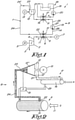
- the cooling system 1 represented in figure 1 is a cooling system for cooling for example the compressed gas produced by a compressor installation comprising a compressor element 2 with an inlet 3 and an outlet 4, said compressor element 2 being connected to a motor 5 for driving the compressor element 2 for compressing a gas flow Q. Further, the cooling system 1 comprises a cooler 6, which is provided downstream of said compressor element 2, for cooling the compressed gas before it is supplied to a net 7 of consumers of compressed gas.
- the cooling installation 1 comprises an ORC 8 according to the invention wherein the above-mentioned cooler 6 is integrated in a heat exchanger 9 which further integrates an evaporator 10 of the ORC 8 for recovering the waste heat of the compressed gas used as a heat source 11 being configured to transform said heat into useful mechanical energy by means of an expander 12 of the ORC 8, for example a turbine driving an electrical generator 13 as shown in the example of figure 1 .
- the ORC comprises a closed circuit 14 containing a two-phase organic working fluid with a boiling temperature below the temperature of the heat source 11, the working fluid being continuously circulated around in the circuit 14 by means of a liquid pump 15 in the direction as indicated with arrows F.
- the working fluid is made to flow consecutively through the evaporator 10 which is in thermal contact with the heat source 11; then through the expander 12 and finally through a condenser 16 before being launched again by the liquid pump 15 for a next cycle in the circuit 14.
- the condenser 16 is part of a heat exchanger 9' in which the condenser 16 is in thermal contact with a cooling element 17 of a cooling circuit 18 which, in the example of figure 1 , is represented as a supply of cold water W taken from a tank 19 to circulate through the condenser 16 by means of a pump 20.
- the condenser 16 is physically located lower than the expander 12, whilst the evaporator 10 is physically located lower than the condenser 16 in such a way that a gravitational flow is possible of the liquid working fluid supplied by the raiser column 24 to the expander 12 and further down from the expander 12 to the condenser 16 and from the condenser 16 to the evaporator 10.
- lower than does not require that all parts of the condenser/evaporator are located lower. It means that the main parts of the condenser/evaporator at a lower level.
- the term should be understood in the context of a requirement for creating a gravitational flow of the liquid part of the working fluid.
- At least the lowest part of the fluid inlet of the condenser 16 is physically located lower than the lowest part 12' of the rotative, active parts 12" of the expander 12, as schematically represented in figure 2 , whilst the lowest part of the fluid inlet of the evaporator 10 is physically located lower than the lowest part of the fluid outlet of the condenser 16, the fluid outlet 22 of the evaporator 10 being connected to the fluid inlet 23 of the expander 12 by means of a so called raiser column 24.
- the ORC 8 is so designed that in normal operating conditions the evaporator 10 is completely filled with boiling working fluid and in that the raiser column is filled over its entire height with a mixture of working fluid in liquid form and of gaseous bubbles of the working fluid, which mixture is supplied to the fluid inlet 23 of the expander 12 through a bended part 24' of the raiser column 24, which bended part 24' extends with at least with a part above the lowest part of the fluid inlet 23 of the expander 12.
- filled with boiling liquid working fluid means that the gaseous bubbles created by boiling do not accumulate at the top of the evaporator 10, such that the working fluid in the evaporator 10 is not separated in a liquid part and a gaseous part accumulated in a space on top of the liquid part as in known ORC's.
- Normal operation of the ORC 8 according to the invention is that the working fluid is made to boil in the evaporator 10 by the heat of the compressed gasses which at the same time are cooled.
- the liquid pump 15 is designed to assure that it is pumping more working fluid to the evaporator 10 than can be evaporated by the heat of the compressed gas to be sure that the evaporator is completely filled with boiling liquid for maximum recovery of the heat from the compressed gas.
- raiser column 24 is a mixture of gas bubbles from the working fluid and of working fluid in liquid form which, as schematically represented in figure 2 , is transported and supplied to the inlet 23 of the expander 12 which therefore has to be chosen amongst types of expanders which are able to deal with such a two phase mixture.
- the bent 24' should be located at the same level or at a higher level than the fluid inlet 23 of the expander in order that the liquid coming with the gas bubbles through the raiser column 24 will flow over the bent 24' and fall downwards by gravity through the expander 12 and to the condenser 16, from where it is supplied again to the evaporator 10 via the conduit 25 of the circuit 14 connecting the condenser 16 with the evaporator 10.
- the gas bubbles produced in the evaporator 10 will tend to rise in the raiser column 24 as well as in the conduit 25 but will take the passage of least resistance via the raiser column 24.
- the ORC continues to circulate the working fluid in the circuit 14 assisted by the force of gravity, thereby providing sufficient cooling of the compressed gas in the evaporator 10 to avoid dangerous conditions to arise until the liquid pump 15 or the expander 12 can be fixed.
- ORC 8 can also be used in other applications than for cooling compressed gas, such as cooling flue gasses, steam, etc.
- Cooling of the condenser 16 can be realized in other ways than in the example of figure 1 , for example by blowing ambient air over the condenser 16 by means of a fan or the like.
- the expander 12 can be any kind of expander capable of generating mechanical energy by expansion of a two phase fluid supply, preferably a volumetric expander like a screw expander or a mechanical cylinder or the like which can accept a mixture of liquid and gaseous working fluid.
- a working fluid is used of which the boiling temperature is lower than 90°C or even lower than 60°C, depending on the temperature of the available heat source 11.
- An example of a suitable organic working fluid is 1,1,1,3,3-pentafluoroprophane.
- the organic fluid could be mixed with a suitable lubricant for the lubrication of at least part of the moving parts of the ORC.
- raiser column 24 should be designed with appropriate dimensions to accommodate the following effects:
- FIG 3 an alternative embodiment is shown of a cooling installation according to the invention which differs from the embodiment of figure 1 in that the ORC circuit is provided with a bypass 26 bridging the inlet 27 and the outlet 28 of the liquid pump 15.
- Said bypass 26 comprising a valve 29 connected to a control 30 for keeping the valve 29 closed during normal operating conditions of the ORC 8 and opening the valve 29 in case the liquid pump 15 would not be operational due to failure or other reasons.
- the control 30 is therefore coupled to a sensor 31 by means of an electric harness 32 for sensing when the liquid pump 15 is not operational.
- the ORC of figure 3 is provided with a bypass 33 bridging the inlet 23 and the outlet 21 of the expander 12 and comprising a valve 34 connected via the harness 32 to the control 30 for keeping the valve 34 closed during normal operating conditions of the ORC 8 and opening the valve 34 in case the input signal coming from a sensor 35 on the expander 12 would indicate that the expander 12 is not operational.
- the control 30 can either open only one of the bypass valves 29 or 34 depending on which of the liquid pump 15 and expander 12 would not be operational or can open both valves 29 and 34 simultaneously.
- the location 36 where the bypass 34 branches to the ORC circuit 14 at the inlet side of the expander 12 would preferably need to be situated at a higher level than the condenser 16.
Landscapes
- Engineering & Computer Science (AREA)
- Chemical & Material Sciences (AREA)
- Combustion & Propulsion (AREA)
- Mechanical Engineering (AREA)
- General Engineering & Computer Science (AREA)
- Engine Equipment That Uses Special Cycles (AREA)
Claims (15)
- ORC (Organischer Rankine-Zyklus) zum Umwandeln von Wärme eines als Wärmequelle (11) verwendeten komprimierten Gases in mechanische Energie, wobei der ORC (8) einen geschlossenen Kreislauf (14) umfasst, der ein zweiphasiges Arbeitsfluid enthält, wobei der Kreislauf (14) eine Flüssigkeitspumpe (15) umfasst, um das Arbeitsfluid in dem Kreislauf (14) fortlaufend durch einen Verdampfer (10) zirkulieren zu lassen, der konfiguriert ist, um in thermischen Kontakt mit der Wärmequelle (11) gebracht zu werden; durch einen Expander (12) zum Umwandeln von thermischer Energie des Arbeitsfluids in mechanische Energie; und durch einen Kondensator (16), der in thermischem Kontakt mit einem Kühlelement (17) steht, dadurch gekennzeichnet, dass der Expander (12) oberhalb des Verdampfers (10) angeordnet ist und dass ein Fluidauslass (22) des Verdampfers (10) mit einem Fluideinlass (23) des Expanders (12) mittels einer sogenannten Steigsäule (24) verbunden ist, wobei der ORC (8) geeignet ist, dass die Steigsäule (24) mit einem Gemisch aus flüssigem Arbeitsfluid
und gasförmigen Blasen des Arbeitsfluids gefüllt ist, wobei das Gemisch dem Expander (12) zugeführt wird, und dass sich die Steigsäule (24) mit mindestens einem Teil auf dem gleichen Niveau oder über dem Niveau des Einlasses (23) des Expanders (12) derart erstreckt, dass ein schwerkraftbedingter Fluss des flüssigen Arbeitsfluids, das von der Steigsäule (24) dem Expander (12) zugeführt wird, möglich ist. - ORC nach Anspruch 1, wobei der Kondensator (16) hauptsächlich auf dem gleichen Niveau oder auf einem niedrigeren Niveau als der Expander (12) derart angeordnet ist, dass ein schwerkraftbedingter Fluss des flüssigen Arbeitsfluids, das von dem Expander (12) dem Kondensator (16) zugeführt wird, möglich ist, wobei vorzugsweise der unterste Teil eines Fluideinlasses des Kondensators (16) niedriger angeordnet ist als der unterste Teil der rotierenden, aktiven Teile des Expanders (12).
- ORC nach einem der vorstehenden Ansprüche, wobei der Verdampfer (10) hauptsächlich auf dem gleichen Niveau oder auf einem niedrigeren Niveau als der Kondensator (16) derart angeordnet ist, dass ein schwerkraftbedingter Fluss des flüssigen Arbeitsfluids, das von dem Kondensator (16) dem Verdampfer (10) zugeführt wird, möglich ist, wobei vorzugsweise der unterste Teil des Fluideinlasses des Verdampfers (10) niedriger angeordnet ist als der unterste Teil eines Fluidauslasses des Kondensators (16).
- ORC nach einem der vorstehenden Ansprüche, wobei der ORC (8) so ausgelegt ist, dass in zumindest einigen Betriebszuständen der Verdampfer (10) vollständig mit siedendem Arbeitsfluid gefüllt ist und dass die Steigsäule (24) mit einem Gemisch aus flüssigem Arbeitsfluid und aus gasförmigen Blasen des Arbeitsfluids gefüllt ist, wobei das Gemisch dem Expander (12) zugeführt wird.
- ORC nach Anspruch 4, wobei die Kapazität der Flüssigkeitspumpe (15) derart vorgesehen ist, dass die Flüssigkeitspumpe (15) mehr Flüssigkeit pumpt als in dem Verdampfer (10) verdampft werden kann.
- ORC nach einem der vorstehenden Ansprüche, wobei der ORC (8) so ausgelegt ist, dass im Falle, dass der Expander (12) und/oder die Flüssigkeitspumpe (15) aufgrund eines Ausfalls oder anderer Gründe nicht betriebsfähig ist/sind, der ORC (8) geeignet ist, um als ein selbstzirkulierender Kreislauf zu arbeiten, der durch thermische, schwerkraftbedingte Effekte auf das Fluid angetrieben wird.
- ORC nach einem der vorstehenden Ansprüche, wobei der ORC-Kreislauf (14) mit einem Bypass (26) versehen ist, der einen Einlass (27) und einen Auslass (28) der Flüssigkeitspumpe (15) überbrückt und der ein Ventil (29) mit einer Steuerung umfasst, um das Ventil (29) während normaler Betriebsbedingungen des ORC (8) geschlossen zu halten und das Ventil (29) für den Fall zu öffnen, dass die Flüssigkeitspumpe (15) aufgrund einer Störung oder aus anderen Gründen nicht betriebsbereit ist.
- ORC nach einem der vorstehenden Ansprüche, wobei der ORC-Kreislauf (14) mit einem Bypass (33) versehen ist, der den Einlass (23) und einen Auslass (21) des Expanders (12) überbrückt und ein Ventil (34) mit einer Steuerung (30) umfasst, um das Ventil (34) während normaler Betriebsbedingungen des ORC (8) geschlossen zu halten und das Ventil (34) für den Fall zu öffnen, dass der Expander (12) aufgrund eines Ausfalls oder aus anderen Gründen nicht betriebsbereit ist.
- ORC nach Anspruch 8, wobei die Steuerung des jeweiligen Ventils (29, 34) so ausgelegt ist, dass bei einem Ausfall des Expanders (12) und/oder der Flüssigkeitspumpe (15) beide Ventile (29, 34) geöffnet werden.
- ORC nach einem der vorstehenden Ansprüche, wobei der Expander (12) geeignet ist, ein Gemisch eines flüssigen und eines gasförmigen Arbeitsfluids aufzunehmen.
- ORC nach einem der vorstehenden Ansprüche, wobei der Expander (12) ein Volumenexpander (12) ist, vorzugsweise ein Schraubenexpander (12).
- ORC nach einem der vorstehenden Ansprüche, geeignet zur Verwendung eines Arbeitsfluids, das ein Schmiermittel umfasst oder als ein Schmiermittel wirkt.
- ORC nach einem der vorstehenden Ansprüche, geeignet zur Verwendung eines Arbeitsfluids, dessen Siedetemperatur unter 90 °C, vorzugsweise unter 60 °C, liegt.
- ORC nach Anspruch 8, wobei der Bypass (33) an der Einlassseite des Expanders (12) an einer Stelle zu dem ORC-Kreislauf (14) abzweigt (36), die auf einem höheren Niveau als der Kondensator (16) liegt.
- Kühlsystem zum Kühlen einer Quelle von Abwärme aus komprimiertem Gas, wobei das Kühlsystem einen ORC (8) nach einem der vorstehenden Ansprüche als einziges Mittel zum Kühlen der Wärmequelle (11) umfasst, ohne dass eine zusätzliche externe Kühlung erforderlich ist, auch bei Nichtbetrieb des Expanders (12) und/oder bei Nichtbetrieb der Flüssigkeitspumpe (15).
Priority Applications (1)
| Application Number | Priority Date | Filing Date | Title |
|---|---|---|---|
| PL16785085T PL3347575T3 (pl) | 2015-09-08 | 2016-08-18 | Obieg orc do przekształcania ciepła odpadowego ze źródła ciepła w energię mechaniczną i system chłodzenia z wykorzystaniem takiego obiegu orc |
Applications Claiming Priority (3)
| Application Number | Priority Date | Filing Date | Title |
|---|---|---|---|
| US201562215249P | 2015-09-08 | 2015-09-08 | |
| BE2016/5642A BE1023753B1 (nl) | 2015-09-08 | 2016-08-17 | Orc om afvalwarmte van een warmtebron om te vormen in mechanische energie en koelsysteem dat van een dergelijke orc gebruikmaakt |
| PCT/BE2016/000040 WO2017041147A1 (en) | 2015-09-08 | 2016-08-18 | Orc for transforming waste heat from a heat source into mechanical energy and cooling system making use of such an orc |
Publications (2)
| Publication Number | Publication Date |
|---|---|
| EP3347575A1 EP3347575A1 (de) | 2018-07-18 |
| EP3347575B1 true EP3347575B1 (de) | 2022-03-02 |
Family
ID=58240431
Family Applications (1)
| Application Number | Title | Priority Date | Filing Date |
|---|---|---|---|
| EP16785085.8A Active EP3347575B1 (de) | 2015-09-08 | 2016-08-18 | Organischer rankine-zyklus zur umwandlung von abwärme aus einer wärmequelle in mechanische energie und kühlsystem mit verwendung solch eines organischen rankine-zyklus |
Country Status (8)
| Country | Link |
|---|---|
| US (1) | US10612423B2 (de) |
| EP (1) | EP3347575B1 (de) |
| KR (1) | KR200491391Y1 (de) |
| CN (1) | CN108474272B (de) |
| DE (1) | DE212016000187U1 (de) |
| ES (1) | ES2914078T3 (de) |
| PL (1) | PL3347575T3 (de) |
| WO (1) | WO2017041147A1 (de) |
Families Citing this family (13)
| Publication number | Priority date | Publication date | Assignee | Title |
|---|---|---|---|---|
| BE1023904B1 (nl) * | 2015-09-08 | 2017-09-08 | Atlas Copco Airpower Naamloze Vennootschap | ORC voor het omvormen van afvalwarmte van een warmtebron in mechanische energie en compressorinstallatie die gebruik maakt van een dergelijke ORC. |
| EP3620621B1 (de) * | 2018-09-07 | 2022-10-26 | HENSOLDT Sensors GmbH | Vorrichtung und verfahren zum kühlen einer elektronischen anordnung |
| IT201900023025A1 (it) * | 2019-12-05 | 2021-06-05 | Mario Ghiringhelli | Apparecchiatura di recupero calore a ciclo rankine con fluidi organici per produrre energia elettrica su una macchina per la produzione di carta tissue |
| US11359576B1 (en) | 2021-04-02 | 2022-06-14 | Ice Thermal Harvesting, Llc | Systems and methods utilizing gas temperature as a power source |
| US11644015B2 (en) | 2021-04-02 | 2023-05-09 | Ice Thermal Harvesting, Llc | Systems and methods for generation of electrical power at a drilling rig |
| US11421663B1 (en) | 2021-04-02 | 2022-08-23 | Ice Thermal Harvesting, Llc | Systems and methods for generation of electrical power in an organic Rankine cycle operation |
| US11592009B2 (en) | 2021-04-02 | 2023-02-28 | Ice Thermal Harvesting, Llc | Systems and methods for generation of electrical power at a drilling rig |
| US11493029B2 (en) | 2021-04-02 | 2022-11-08 | Ice Thermal Harvesting, Llc | Systems and methods for generation of electrical power at a drilling rig |
| US11480074B1 (en) | 2021-04-02 | 2022-10-25 | Ice Thermal Harvesting, Llc | Systems and methods utilizing gas temperature as a power source |
| US11293414B1 (en) | 2021-04-02 | 2022-04-05 | Ice Thermal Harvesting, Llc | Systems and methods for generation of electrical power in an organic rankine cycle operation |
| US11280322B1 (en) | 2021-04-02 | 2022-03-22 | Ice Thermal Harvesting, Llc | Systems for generating geothermal power in an organic Rankine cycle operation during hydrocarbon production based on wellhead fluid temperature |
| US11486370B2 (en) | 2021-04-02 | 2022-11-01 | Ice Thermal Harvesting, Llc | Modular mobile heat generation unit for generation of geothermal power in organic Rankine cycle operations |
| DE102022110580A1 (de) | 2022-04-29 | 2023-11-02 | Dürr Systems Ag | Anlage mit wärmetauscher und anlagen-betriebsverfahren |
Family Cites Families (22)
| Publication number | Priority date | Publication date | Assignee | Title |
|---|---|---|---|---|
| FR777778A (fr) * | 1934-08-28 | 1935-02-28 | Installation pour la production de force motrice | |
| FR1010036A (fr) * | 1948-07-23 | 1952-06-06 | Procédé pour l'utilisation de la chaleur de la terre | |
| US3747333A (en) * | 1971-01-29 | 1973-07-24 | Steam Eng Syst Inc | Steam system |
| US3686867A (en) * | 1971-03-08 | 1972-08-29 | Francis R Hull | Regenerative ranking cycle power plant |
| US3938335A (en) * | 1973-07-30 | 1976-02-17 | Marwick Edward F | Heat engines |
| JPS57148011A (en) * | 1981-03-09 | 1982-09-13 | Koji Akagawa | Motive power generator employing low-temperature energy source for natural circulating force |
| JPH0979504A (ja) | 1995-09-20 | 1997-03-28 | Babcock Hitachi Kk | 排熱回収ボイラ洗浄方法 |
| RU27395U1 (ru) | 2002-10-23 | 2003-01-27 | Кушин Виктор Владимирович | Гравитационная паросиловая гидроэлектростанция |
| US7665304B2 (en) * | 2004-11-30 | 2010-02-23 | Carrier Corporation | Rankine cycle device having multiple turbo-generators |
| AT503167B1 (de) * | 2006-02-06 | 2007-10-15 | Siegfried Prugner | Anordnung zum umwandeln von strömungsenergie |
| US20090249779A1 (en) * | 2006-06-12 | 2009-10-08 | Daw Shien Scientific Research & Development, Inc. | Efficient vapor (steam) engine/pump in a closed system used at low temperatures as a better stirling heat engine/refrigerator |
| GB2446404B (en) * | 2006-12-05 | 2011-11-09 | Pera Innovation Ltd | Generation of electricity |
| CA2698334A1 (en) * | 2007-10-12 | 2009-04-16 | Doty Scientific, Inc. | High-temperature dual-source organic rankine cycle with gas separations |
| US20100034684A1 (en) * | 2008-08-07 | 2010-02-11 | General Electric Company | Method for lubricating screw expanders and system for controlling lubrication |
| JP5495293B2 (ja) | 2009-07-06 | 2014-05-21 | 株式会社日立産機システム | 圧縮機 |
| US8869531B2 (en) * | 2009-09-17 | 2014-10-28 | Echogen Power Systems, Llc | Heat engines with cascade cycles |
| KR20100044737A (ko) | 2010-02-28 | 2010-04-30 | (주)이노씨엔이 | 랭킨사이클을 활용한 공업로 배기가스 냉각시스템 |
| FR2985767B1 (fr) | 2012-01-18 | 2019-03-15 | IFP Energies Nouvelles | Dispositif de controle d'un fluide de travail dans un circuit ferme fonctionnant selon un cycle de rankine et procede utilisant un tel dispositif |
| CN105074140A (zh) * | 2013-01-28 | 2015-11-18 | 伊顿公司 | 具有润滑回路的有机朗肯循环系统 |
| US20150377080A1 (en) * | 2013-01-28 | 2015-12-31 | Eaton Corporation | Organic rankine cycle system with lubrication circuit |
| EP2865854B1 (de) | 2013-10-23 | 2021-08-18 | Orcan Energy AG | Vorrichtung und Verfahren zum zuverlässigen Starten von ORC Systemen |
| JP6827492B2 (ja) | 2019-04-17 | 2021-02-10 | 株式会社三井ハイテック | 積層鉄心の製造方法 |
-
2016
- 2016-08-18 KR KR2020187000024U patent/KR200491391Y1/ko active IP Right Grant
- 2016-08-18 EP EP16785085.8A patent/EP3347575B1/de active Active
- 2016-08-18 US US15/757,350 patent/US10612423B2/en active Active
- 2016-08-18 DE DE212016000187.6U patent/DE212016000187U1/de active Active
- 2016-08-18 WO PCT/BE2016/000040 patent/WO2017041147A1/en active Application Filing
- 2016-08-18 PL PL16785085T patent/PL3347575T3/pl unknown
- 2016-08-18 CN CN201680059381.8A patent/CN108474272B/zh active Active
- 2016-08-18 ES ES16785085T patent/ES2914078T3/es active Active
Also Published As
| Publication number | Publication date |
|---|---|
| US10612423B2 (en) | 2020-04-07 |
| ES2914078T3 (es) | 2022-06-07 |
| CN108474272A (zh) | 2018-08-31 |
| PL3347575T3 (pl) | 2022-06-20 |
| KR20180001994U (ko) | 2018-07-02 |
| CN108474272B (zh) | 2020-08-14 |
| WO2017041147A1 (en) | 2017-03-16 |
| EP3347575A1 (de) | 2018-07-18 |
| US20180252120A1 (en) | 2018-09-06 |
| DE212016000187U1 (de) | 2018-04-16 |
| KR200491391Y1 (ko) | 2020-04-01 |
Similar Documents
| Publication | Publication Date | Title |
|---|---|---|
| EP3347575B1 (de) | Organischer rankine-zyklus zur umwandlung von abwärme aus einer wärmequelle in mechanische energie und kühlsystem mit verwendung solch eines organischen rankine-zyklus | |
| US10619520B2 (en) | Controlled organic Rankine cycle system for recovery and conversion of thermal energy | |
| US8857186B2 (en) | Heat engine cycles for high ambient conditions | |
| EP2646657B1 (de) | Wärmekraftmaschinen mit parallelem zyklus | |
| US8869531B2 (en) | Heat engines with cascade cycles | |
| US20140033711A1 (en) | Multiple organic rankine cycle system and method | |
| CN104185717B (zh) | 用于从双热源回收废热的系统和方法 | |
| KR101553196B1 (ko) | 유기 랭킨 바이너리 사이클 발전시스템 | |
| US20150075210A1 (en) | Method for charging and discharging a heat accumulator and plant for storing and releasing thermal energy, suitable for this method | |
| JP5527513B2 (ja) | 流体機械駆動システム | |
| EP2458165A2 (de) | Wärmebetriebenes Energieerzeugungssystem | |
| EP3258094A1 (de) | Wärmetauscher, energierückgewinnungsvorrichtung und schiff | |
| US9540961B2 (en) | Heat sources for thermal cycles | |
| RU2701973C1 (ru) | Органический цикл рэнкина для преобразования сбросного тепла источника тепла в механическую энергию и система охлаждения, использующая такой цикл | |
| RU2575674C2 (ru) | Тепловые двигатели с параллельным циклом |
Legal Events
| Date | Code | Title | Description |
|---|---|---|---|
| STAA | Information on the status of an ep patent application or granted ep patent |
Free format text: STATUS: UNKNOWN |
|
| STAA | Information on the status of an ep patent application or granted ep patent |
Free format text: STATUS: THE INTERNATIONAL PUBLICATION HAS BEEN MADE |
|
| PUAI | Public reference made under article 153(3) epc to a published international application that has entered the european phase |
Free format text: ORIGINAL CODE: 0009012 |
|
| STAA | Information on the status of an ep patent application or granted ep patent |
Free format text: STATUS: REQUEST FOR EXAMINATION WAS MADE |
|
| 17P | Request for examination filed |
Effective date: 20180312 |
|
| AK | Designated contracting states |
Kind code of ref document: A1 Designated state(s): AL AT BE BG CH CY CZ DE DK EE ES FI FR GB GR HR HU IE IS IT LI LT LU LV MC MK MT NL NO PL PT RO RS SE SI SK SM TR |
|
| AX | Request for extension of the european patent |
Extension state: BA ME |
|
| DAV | Request for validation of the european patent (deleted) | ||
| DAX | Request for extension of the european patent (deleted) | ||
| GRAP | Despatch of communication of intention to grant a patent |
Free format text: ORIGINAL CODE: EPIDOSNIGR1 |
|
| STAA | Information on the status of an ep patent application or granted ep patent |
Free format text: STATUS: GRANT OF PATENT IS INTENDED |
|
| INTG | Intention to grant announced |
Effective date: 20211208 |
|
| GRAS | Grant fee paid |
Free format text: ORIGINAL CODE: EPIDOSNIGR3 |
|
| GRAA | (expected) grant |
Free format text: ORIGINAL CODE: 0009210 |
|
| STAA | Information on the status of an ep patent application or granted ep patent |
Free format text: STATUS: THE PATENT HAS BEEN GRANTED |
|
| AK | Designated contracting states |
Kind code of ref document: B1 Designated state(s): AL AT BE BG CH CY CZ DE DK EE ES FI FR GB GR HR HU IE IS IT LI LT LU LV MC MK MT NL NO PL PT RO RS SE SI SK SM TR |
|
| REG | Reference to a national code |
Ref country code: GB Ref legal event code: FG4D |
|
| REG | Reference to a national code |
Ref country code: CH Ref legal event code: EP Ref country code: AT Ref legal event code: REF Ref document number: 1472396 Country of ref document: AT Kind code of ref document: T Effective date: 20220315 |
|
| REG | Reference to a national code |
Ref country code: DE Ref legal event code: R096 Ref document number: 602016069629 Country of ref document: DE |
|
| REG | Reference to a national code |
Ref country code: IE Ref legal event code: FG4D |
|
| REG | Reference to a national code |
Ref country code: FI Ref legal event code: FGE |
|
| REG | Reference to a national code |
Ref country code: NL Ref legal event code: FP |
|
| REG | Reference to a national code |
Ref country code: ES Ref legal event code: FG2A Ref document number: 2914078 Country of ref document: ES Kind code of ref document: T3 Effective date: 20220607 |
|
| REG | Reference to a national code |
Ref country code: SE Ref legal event code: TRGR |
|
| REG | Reference to a national code |
Ref country code: GR Ref legal event code: EP Ref document number: 20220401045 Country of ref document: GR Effective date: 20220608 |
|
| REG | Reference to a national code |
Ref country code: LT Ref legal event code: MG9D |
|
| PG25 | Lapsed in a contracting state [announced via postgrant information from national office to epo] |
Ref country code: RS Free format text: LAPSE BECAUSE OF FAILURE TO SUBMIT A TRANSLATION OF THE DESCRIPTION OR TO PAY THE FEE WITHIN THE PRESCRIBED TIME-LIMIT Effective date: 20220302 Ref country code: NO Free format text: LAPSE BECAUSE OF FAILURE TO SUBMIT A TRANSLATION OF THE DESCRIPTION OR TO PAY THE FEE WITHIN THE PRESCRIBED TIME-LIMIT Effective date: 20220602 Ref country code: LT Free format text: LAPSE BECAUSE OF FAILURE TO SUBMIT A TRANSLATION OF THE DESCRIPTION OR TO PAY THE FEE WITHIN THE PRESCRIBED TIME-LIMIT Effective date: 20220302 Ref country code: HR Free format text: LAPSE BECAUSE OF FAILURE TO SUBMIT A TRANSLATION OF THE DESCRIPTION OR TO PAY THE FEE WITHIN THE PRESCRIBED TIME-LIMIT Effective date: 20220302 Ref country code: BG Free format text: LAPSE BECAUSE OF FAILURE TO SUBMIT A TRANSLATION OF THE DESCRIPTION OR TO PAY THE FEE WITHIN THE PRESCRIBED TIME-LIMIT Effective date: 20220602 |
|
| REG | Reference to a national code |
Ref country code: AT Ref legal event code: MK05 Ref document number: 1472396 Country of ref document: AT Kind code of ref document: T Effective date: 20220302 |
|
| PG25 | Lapsed in a contracting state [announced via postgrant information from national office to epo] |
Ref country code: LV Free format text: LAPSE BECAUSE OF FAILURE TO SUBMIT A TRANSLATION OF THE DESCRIPTION OR TO PAY THE FEE WITHIN THE PRESCRIBED TIME-LIMIT Effective date: 20220302 |
|
| PG25 | Lapsed in a contracting state [announced via postgrant information from national office to epo] |
Ref country code: SM Free format text: LAPSE BECAUSE OF FAILURE TO SUBMIT A TRANSLATION OF THE DESCRIPTION OR TO PAY THE FEE WITHIN THE PRESCRIBED TIME-LIMIT Effective date: 20220302 Ref country code: SK Free format text: LAPSE BECAUSE OF FAILURE TO SUBMIT A TRANSLATION OF THE DESCRIPTION OR TO PAY THE FEE WITHIN THE PRESCRIBED TIME-LIMIT Effective date: 20220302 Ref country code: RO Free format text: LAPSE BECAUSE OF FAILURE TO SUBMIT A TRANSLATION OF THE DESCRIPTION OR TO PAY THE FEE WITHIN THE PRESCRIBED TIME-LIMIT Effective date: 20220302 Ref country code: PT Free format text: LAPSE BECAUSE OF FAILURE TO SUBMIT A TRANSLATION OF THE DESCRIPTION OR TO PAY THE FEE WITHIN THE PRESCRIBED TIME-LIMIT Effective date: 20220704 Ref country code: EE Free format text: LAPSE BECAUSE OF FAILURE TO SUBMIT A TRANSLATION OF THE DESCRIPTION OR TO PAY THE FEE WITHIN THE PRESCRIBED TIME-LIMIT Effective date: 20220302 Ref country code: CZ Free format text: LAPSE BECAUSE OF FAILURE TO SUBMIT A TRANSLATION OF THE DESCRIPTION OR TO PAY THE FEE WITHIN THE PRESCRIBED TIME-LIMIT Effective date: 20220302 Ref country code: AT Free format text: LAPSE BECAUSE OF FAILURE TO SUBMIT A TRANSLATION OF THE DESCRIPTION OR TO PAY THE FEE WITHIN THE PRESCRIBED TIME-LIMIT Effective date: 20220302 |
|
| PG25 | Lapsed in a contracting state [announced via postgrant information from national office to epo] |
Ref country code: IS Free format text: LAPSE BECAUSE OF FAILURE TO SUBMIT A TRANSLATION OF THE DESCRIPTION OR TO PAY THE FEE WITHIN THE PRESCRIBED TIME-LIMIT Effective date: 20220702 Ref country code: AL Free format text: LAPSE BECAUSE OF FAILURE TO SUBMIT A TRANSLATION OF THE DESCRIPTION OR TO PAY THE FEE WITHIN THE PRESCRIBED TIME-LIMIT Effective date: 20220302 |
|
| REG | Reference to a national code |
Ref country code: DE Ref legal event code: R097 Ref document number: 602016069629 Country of ref document: DE |
|
| PLBE | No opposition filed within time limit |
Free format text: ORIGINAL CODE: 0009261 |
|
| STAA | Information on the status of an ep patent application or granted ep patent |
Free format text: STATUS: NO OPPOSITION FILED WITHIN TIME LIMIT |
|
| PG25 | Lapsed in a contracting state [announced via postgrant information from national office to epo] |
Ref country code: DK Free format text: LAPSE BECAUSE OF FAILURE TO SUBMIT A TRANSLATION OF THE DESCRIPTION OR TO PAY THE FEE WITHIN THE PRESCRIBED TIME-LIMIT Effective date: 20220302 |
|
| 26N | No opposition filed |
Effective date: 20221205 |
|
| PG25 | Lapsed in a contracting state [announced via postgrant information from national office to epo] |
Ref country code: SI Free format text: LAPSE BECAUSE OF FAILURE TO SUBMIT A TRANSLATION OF THE DESCRIPTION OR TO PAY THE FEE WITHIN THE PRESCRIBED TIME-LIMIT Effective date: 20220302 |
|
| PG25 | Lapsed in a contracting state [announced via postgrant information from national office to epo] |
Ref country code: MC Free format text: LAPSE BECAUSE OF FAILURE TO SUBMIT A TRANSLATION OF THE DESCRIPTION OR TO PAY THE FEE WITHIN THE PRESCRIBED TIME-LIMIT Effective date: 20220302 |
|
| P01 | Opt-out of the competence of the unified patent court (upc) registered |
Effective date: 20230602 |
|
| PGFP | Annual fee paid to national office [announced via postgrant information from national office to epo] |
Ref country code: NL Payment date: 20230826 Year of fee payment: 8 Ref country code: LU Payment date: 20230828 Year of fee payment: 8 |
|
| PGFP | Annual fee paid to national office [announced via postgrant information from national office to epo] |
Ref country code: IT Payment date: 20230822 Year of fee payment: 8 Ref country code: IE Payment date: 20230828 Year of fee payment: 8 Ref country code: GB Payment date: 20230828 Year of fee payment: 8 Ref country code: FI Payment date: 20230825 Year of fee payment: 8 Ref country code: ES Payment date: 20230901 Year of fee payment: 8 Ref country code: CH Payment date: 20230903 Year of fee payment: 8 |
|
| PGFP | Annual fee paid to national office [announced via postgrant information from national office to epo] |
Ref country code: SE Payment date: 20230827 Year of fee payment: 8 Ref country code: PL Payment date: 20230801 Year of fee payment: 8 Ref country code: GR Payment date: 20230829 Year of fee payment: 8 Ref country code: FR Payment date: 20230825 Year of fee payment: 8 Ref country code: DE Payment date: 20230829 Year of fee payment: 8 Ref country code: BE Payment date: 20230828 Year of fee payment: 8 |
|
| PG25 | Lapsed in a contracting state [announced via postgrant information from national office to epo] |
Ref country code: HU Free format text: LAPSE BECAUSE OF FAILURE TO SUBMIT A TRANSLATION OF THE DESCRIPTION OR TO PAY THE FEE WITHIN THE PRESCRIBED TIME-LIMIT; INVALID AB INITIO Effective date: 20160818 |
|
| PG25 | Lapsed in a contracting state [announced via postgrant information from national office to epo] |
Ref country code: CY Free format text: LAPSE BECAUSE OF FAILURE TO SUBMIT A TRANSLATION OF THE DESCRIPTION OR TO PAY THE FEE WITHIN THE PRESCRIBED TIME-LIMIT Effective date: 20220302 |