EP3346829B1 - An animal drinker - Google Patents
An animal drinker Download PDFInfo
- Publication number
- EP3346829B1 EP3346829B1 EP16766095.0A EP16766095A EP3346829B1 EP 3346829 B1 EP3346829 B1 EP 3346829B1 EP 16766095 A EP16766095 A EP 16766095A EP 3346829 B1 EP3346829 B1 EP 3346829B1
- Authority
- EP
- European Patent Office
- Prior art keywords
- container
- animal
- drinker
- compartment
- support
- Prior art date
- Legal status (The legal status is an assumption and is not a legal conclusion. Google has not performed a legal analysis and makes no representation as to the accuracy of the status listed.)
- Active
Links
Images

Classifications
-
- A—HUMAN NECESSITIES
- A01—AGRICULTURE; FORESTRY; ANIMAL HUSBANDRY; HUNTING; TRAPPING; FISHING
- A01K—ANIMAL HUSBANDRY; AVICULTURE; APICULTURE; PISCICULTURE; FISHING; REARING OR BREEDING ANIMALS, NOT OTHERWISE PROVIDED FOR; NEW BREEDS OF ANIMALS
- A01K7/00—Watering equipment for stock or game
-
- A—HUMAN NECESSITIES
- A01—AGRICULTURE; FORESTRY; ANIMAL HUSBANDRY; HUNTING; TRAPPING; FISHING
- A01K—ANIMAL HUSBANDRY; AVICULTURE; APICULTURE; PISCICULTURE; FISHING; REARING OR BREEDING ANIMALS, NOT OTHERWISE PROVIDED FOR; NEW BREEDS OF ANIMALS
- A01K7/00—Watering equipment for stock or game
- A01K7/02—Automatic devices
- A01K7/04—Automatic devices actuated by float
Definitions
- the present invention relates to an animal drinker, and in particular, though not limited to an animal drink bowl.
- Animal drinkers are provided in order to provide a supply of drinking water to animals, and typically, are provided in the form of an animal drink bowl or a drink trough.
- Drink bowls in general, are secured to a wall or structure, and in general comprise a bowl which typically is divided into two compartments, namely, a drink compartment in which drinking water is accessible to an animal, and a level control compartment within which a float valve is provided, and from which a supply of water is delivered to the bowl, with the level of water controlled by the float control valve.
- a communicating opening is generally provided between the drink compartment and the level control compartment in order to maintain the level of water in the drink compartment at a similar level to the level of water in the level control compartment.
- the level control compartment in general is closed in order to prevent animals gaining access to the float control valve.
- Animal drink troughs in general comprise an elongated trough in which water in the trough is accessible to animals, and in general, a level control compartment is located at one end of the drink trough into which a supply of water is delivered through a float control valve.
- the level control compartment communicates with the remainder of the trough through a communicating opening in order to maintain the water level in the trough substantially similar to the level of water in the level control compartment.
- the flexible conduit can be snagged by animals, and thus disconnected from the trough, and additionally, with the passage of time, the flexible conduit may deteriorate as a result of pivoting of the trough between the operative state and the discharge state, and in general, the deterioration of the flexible conduit results in cracking of the conduit, which in turn results in water leaking from the flexible conduit. This is undesirable.
- PCT Specification No. WO 99/05905 of Booth discloses an animal feeding trough which may contain liquid or other forms of feedstuffs.
- the trough is pivotally coupled between a pair of upstanding frame members about a substantially central longitudinal axis which extends parallel to the length of the trough for facilitating pivoting of the trough between an operative state for presenting feedstuffs to an animal, or a discharge state for discharging feedstuffs therefrom.
- a feed supply port for introducing liquid into the trough is also provided.
- British Patent Specification No. 238,019 of Bingham discloses a drinking appliance for an animal which comprises a container for drinking water which is pivotally coupled to a support frame.
- a valve is provided for supplying water to the container.
- the weight of the water pivots the frame downwardly against a spring.
- the container is urged upwardly by the spring resulting in the valve being opened to supply more water to the container.
- U.S. Patent Specification No. 3,101,071 of Frye discloses an animal waterer which comprises a semi-cylindrical container which is pivotally mounted about an axis defined by the semi-cylindrical container between an operative state for presenting water to an animal and a discharge state for discharging water from the container.
- U.S. Patent Specification No. 1,854,117 of Devitt discloses a trough for supplying water to chickens which comprises a pivotally mounted water trough which is located in a substantially rectangular casing.
- the water trough is pivoted off-centre, and is urged by a spring into a normal position for presenting water to the chickens.
- a latch which is float actuated releaseably retains the trough in the normal position. On the trough being filled with water, the latch releases the trough to discharge water therefrom for cleaning the trough.
- the present invention is directed towards providing such an animal drinker.
- an animal drinker comprising a support, a container defining a hollow interior region for a drinkable liquid and an open mouth for accommodating a muzzle of an animal to the hollow interior region of the container, and an inlet port for accommodating the drinkable liquid to the hollow interior region of the container, the container being pivotally mounted on the support, and being pivotal relative to the support and the inlet port between an operative state for receiving the drinkable liquid from the inlet port and for presenting the drinkable liquid to an animal, and a discharge state for discharging the liquid therefrom, wherein a mounting means comprising a mounting plate for mounting the support to a structure is provided, the support comprises a support framework extending forwardly from the mounting plate, the inlet port is rigidly secured to the support framework, and the container is pivotally coupled to the support framework to one side thereof about a main pivot axis extending perpendicularly relative to the mounting plate and is pivotal about the main pivot axis through an angle of at least 90° between the operative state and the discharge state
- a retaining means is provided for releaseably retaining the container in the operative state.
- a level control valve is located upstream of the inlet port, and the drinkable liquid is delivered to the inlet port through the level control valve.
- the level control valve comprises a float control valve.
- the container is pivotal through an angle of at least 135° between the operative state and the discharge state, and preferably through an angle of up to approximately 180°.
- the hollow interior region of the container is divided by a partition wall into a drink compartment in which the drinkable liquid is accessible through the open mouth, and a level control compartment in which a float of the float control valve is accommodated.
- a communicating opening is provided in the partition wall communicating the drink compartment with the level control compartment.
- the framework defines a muzzle accommodating opening for accommodating a muzzle of an animal to the drink compartment when the container is in the operative state.
- a closure plate is located in the support for closing a portion of the open mouth of the container which communicates with the level control compartment, and preferably, the closure plate is located in the framework, and advantageously, the closure plate defines with the framework the muzzle accommodating opening.
- the retaining means is releaseably engageable with the support, and advantageously, is releaseably engageable with the closure plate.
- the retaining means comprises a latch, and in another aspect of the invention the retaining means is manually operable.
- the animal drinker is configured as an animal drink bowl.
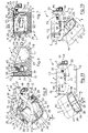
- an animal drinker in this embodiment of the invention an animal drink bowl, indicated generally by the reference numeral 1, for securing to a wall or other structure and for providing a drinkable liquid, in this embodiment of the invention drinking water to an animal, for example, a cow, a calf or the like.
- the animal drink bowl 1 comprises a support 2 and a mounting means formed by a mounting plate 3 for securing to a wall or other structure for securing the support 2 to a wall or other structure.
- the support 2 comprises a support framework 5 extending forwardly from the mounting plate 3.
- a container 7 for the drinking water is movably mounted on the support framework 5, and in this embodiment of the invention is pivotally coupled to the support framework 5 about a main pivot axis 8, which extends perpendicularly relative to the mounting plate 3.
- the container 7 is pivotal about the main pivot axis 8 between an operative state illustrated in Figs. 1 to 8 for presenting water to an animal, and a discharge state illustrated in Fig. 11 for facilitating discharge of water from the container 7 and also for facilitating the discharge and removal of dirt, debris and other foreign matter from the container 7.
- the support framework 5 comprises a pair of spaced apart side members 9 and 10 extending forwardly from the mounting plate 3, which are joined by a front cross-member 11.
- the support framework 5 is of tubular steel
- the mounting plate 3 is of steel plate material.
- a plurality of screw accommodating holes 12 formed in the mounting plate 3 accommodate screws or other fixing elements for securing the mounting plate 3 to a wall or other structure to which the drink bowl 1 is to be secured.
- a pair of spaced apart downwardly extending mounting members 14 of steel plate material extend downwardly from the side member 9 for carrying a main pivot shaft 15, which defines the main pivot axis 8, and to which the container 7 is pivotally connected about the main pivot axis 8 as will be described in more detail below.
- the container 7 comprises a base 17, a pair of spaced apart side walls 18 and 19 extending upwardly from the base 17 and joined by spaced apart front and rear end walls 20 and 21 which also extend upwardly from the base 17.
- the base 17, the side walls 18 and 19 and the front and rear end walls 20 and 21 together define a hollow interior region 23 of the container 7.
- the side walls 18 and 19 and the front and rear end walls 20 and 21 define an open mouth 24 to the hollow interior region 23.
- a partition wall 25 extending upwardly from the base 17 across the hollow interior region 23 between the side walls 18 and 19 divides the hollow interior 23 into a forward drink compartment 28 and a rearward level control compartment 29 into which drinking water is delivered, and in which the level of water in the level control compartment 29, and in turn the forward drink compartment 28 is controlled.
- a communicating opening 30 extending through the partition wall 25 communicates the forward drink compartment 28 with the rearward level control compartment 29 for maintaining the level of water in the drink compartment 28 substantially similar to the level of water in the level control compartment 29.
- An elongated mounting bracket 32 extends from and along the side wall 18 of the container 7 and defines an elongated bore 34 through which the main pivot shaft 15 extends for pivotally mounting the container 7 on the main pivot shaft 15 about the main pivot axis 8 between the operative state and the discharge state.
- the container 7 together with the mounting bracket 39 are formed in one piece of plastics material, typically, polyethylene material, by a rotational moulding process.
- the mounting members 14, the main pivot shaft 15 and the mounting bracket 32 are configured relative to the support framework 5 and the container 7, so that the container 7 is pivotal through almost 180° between the operative state and the discharge state.
- a level control valve which in this embodiment of the invention comprises a float control valve 35, is rigidly mounted on a support plate 37 which in turn is rigidly secured to and extends downwardly from the side member 10 of the support framework 5.
- the float control valve 35 terminates in a downstream inlet port 39 through which drinking water is supplied into the level control compartment 29 of the container 7 from the float control valve 35.
- a float 40 of the float control valve 35 is carried on a support arm 21 which in turn is pivotally coupled to the float control valve 35 by a pivot pin 42, so that as the float 40 rises and falls within the level control compartment 29, the supply of water through the float control valve 35 and the inlet port 39 to the level control compartment 29 is controlled in order to control the level of water in the level control compartment 29, and in turn in the drink compartment 28.
- the operation of such float control valves 35 for controlling water level in a container will be well known to those skilled in the art.
- An elbow connector 44 which is connected to the float control valve 35 is configured to receive a drinking water supply from a drinking water source, for example, a mains water supply.
- a downwardly extending slot 45 extends downwardly into the side wall 19 of the container 7 for accommodating the float control valve 35 when the container 7 is in the operative state.
- a closure plate 46 of steel plate material is secured to and extends between rearward portions 47 of the side members 9 and 10 of the support framework 5 for closing a portion of the open mouth 28 of the container 7 which communicates with the level control compartment 29 when the container 7 is in the operative state. This prevents access by animals to the level control compartment 29.
- the closure plate 46 defines with forward portions 48 of the side members 9 and 10 and with the front cross-member 11 a muzzle accommodating opening 49 to the drink compartment 28 for accommodating the muzzle of an animal into the drink compartment 28 for drinking water therefrom.
- a retaining means in this embodiment of the invention a latch 50 is pivotally coupled to the rear end wall 21 of the container 7 by a pivot pin 52 and is releaseably engageable in a receiving slot 53, which is formed in the closure plate 46 for releaseably retaining the container 7 in the operative state.
- a latching element 54 of the latch 50 is releaseably engageable with the closure plate 46 adjacent an end 55 of the receiving slot 53 when the container is in the operative state for releaseably retaining the container in the operative state.
- a compression spring 56 acting between the latch 50 and the side wall 19 of the container 7 urges the latch 50 into a latching state with the latching element 54 engaging the closure plate 46 adjacent the end 55 of the receiving slot 53 for in turn releaseably retaining the container 7 in the operative state.
- the drink bowl 1 In use, with the drink bowl 1 mounted by the mounting plate 3 to a wall or other structure, and a drinking water supply connected to the elbow connector 44, and with the container 7 in the operative state and releaseably retained therein by the latch 50, the drink bowl 1 is ready for use. Water is supplied through the float control valve 35 into the level control compartment 29 where the level of water in the level control compartment 29 and in turn in the drink compartment 28 is controlled by the float control valve 35. As animals drink from the drink compartment 28, the float control valve 35 maintains the water level in the level control compartment 29 and in turn in the drink compartment 28 substantially constant.
- the latch 50 When it is desired to clean the container 7, the latch 50 is manually pivoted in the direction of the arrow A in order to disengage the latch element 54 from the closure plate 46 adjacent an end 55 of the receiving slot 53. Once the latch element 54 is disengaged from the closure plate 46, the container 7 is pivoted downwardly in the direction of the arrow B about the main pivot axis 8 into the discharge state illustrated in Fig. 11 . In the discharge state, water in the drink compartment 28 and in the level control compartment 29 is discharged from the container 7 through the open mouth 24 thereof, and dirt, debris and other foreign matter located in the drink compartment 28 and the level control compartment 29 is similarly discharged from the drink and level control compartments 28 and 29 through the open mouth 24. The two compartments 28 and 29 can then be wiped clean.
- the container 7 When cleaned, the container 7 is pivoted in the direction of the arrow C from the discharge state to the operative state.
- the latch 50 engages the receiving slot 53, and when the container 7 is fully urged into the operative state, the compression spring 56 urges the latching element 54 of the latch 50 into engagement with the closure plate 46 adjacent the end 55 of the receiving slot 53, so that the latch 50 is releaseably secured in the receiving slot 53 for in turn releaseably retaining the container 7 in the operative state.
- the container 7 is pivotal about the main pivot axis 8 through an angle of up to approximately 180° between the operative state and the discharge state, and in general, it is envisaged that the container 7 will be pivoted through an angle of up to almost 180° from the operative state to the discharge state, and at least through an angle of 135° from the operative state to the discharge state, as illustrated in Fig. 11 , in order to discharge dirt, debris and other foreign matter from the drink compartment 28 and the level control compartment 29 during cleaning of the container 7.
- a particularly important advantage of the invention is that the container 7 can be readily easily cleaned by merely pivoting the container 7 from the operative state to the discharge state.
- the pivoting of the container from the operative state to the discharge state can be carried out while the float control valve 35 and the elbow connector 44 remain in a fixed state relative to the support 2 of the drink bowl 1.
- the float control valve 35 and the elbow connector 44 remain in a fixed state relative to the support 2 of the drink bowl 1.
- the drinker has been described as comprising a drink bowl, it will be readily apparent to those skilled in the art that the drinker instead of being provided in the form of a drink bowl, may be provided in the form of an elongated drinking trough.
- the container would be configured as an elongated drink trough and would be pivotal relative to an appropriately shaped framework to which the float control valve would be rigidly connected.
- the components of the drink bowl according to the invention have been described as being of specific materials, the components may be of any other suitable material, for example, all the components of the drink bowl may be of the same material, such as a metal material, a plastics material, or any other suitable material, or mix of materials.
- the support has been described as comprising a support framework, the support framework may be of any other suitable shape and/or construction.
- the mounting means may comprise any other suitable mounting means beside the mounting plate, for example, the mounting means may be provided by a mounting frame or a mounting framework, or a mounting plate of any other suitable shape, size and/or construction.
- the container may be of any other suitable shape or configuration, and it will also be appreciated that while it is desirable, it may not be essential in all cases that the container be divided by a partition wall into a drink compartment and a level control compartment. Indeed, it is envisaged that the partition wall dividing the hollow interior region of the container into a level control compartment and a drink compartment instead of being provided by a partition wall located in the container, the partition wall may extend into the container from the support, for example, the partition wall could extend downwardly into the hollow interior region of the container from the closure plate.
- any other suitable level control valve may be provided.
- any other suitable connector may be provided for connecting a drinking water supply to the level control valve.
- animal drinker has been described as being suitable for providing a supply of water to cows, calves and the like, it will be readily apparent to those skilled in the art that the animal drinker may be suitably sized and shaped for many other types of animals, for example, horses, ponies, donkeys, mules, goats, sheep, dogs, cats, and indeed larger animals of the type commonly found in animal zoos.
- the retaining means in this embodiment of the invention for retaining the container in the discharge state has been described as comprising a latch, any other suitable retaining means may be provided, and the retaining means may be manually operable or automatically operable.
- the retaining means may comprise a magnet, a clasp or any other suitable retaining means.
Landscapes
- Life Sciences & Earth Sciences (AREA)
- Environmental Sciences (AREA)
- Animal Husbandry (AREA)
- Biodiversity & Conservation Biology (AREA)
- Feeding And Watering For Cattle Raising And Animal Husbandry (AREA)
Applications Claiming Priority (2)
| Application Number | Priority Date | Filing Date | Title |
|---|---|---|---|
| IES20150284 | 2015-09-08 | ||
| PCT/IE2016/000015 WO2017042795A1 (en) | 2015-09-08 | 2016-09-06 | An animal drinker |
Publications (2)
| Publication Number | Publication Date |
|---|---|
| EP3346829A1 EP3346829A1 (en) | 2018-07-18 |
| EP3346829B1 true EP3346829B1 (en) | 2022-05-25 |
Family
ID=58239283
Family Applications (1)
| Application Number | Title | Priority Date | Filing Date |
|---|---|---|---|
| EP16766095.0A Active EP3346829B1 (en) | 2015-09-08 | 2016-09-06 | An animal drinker |
Country Status (4)
| Country | Link |
|---|---|
| EP (1) | EP3346829B1 (pl) |
| GB (1) | GB2561708B (pl) |
| PL (1) | PL3346829T3 (pl) |
| WO (1) | WO2017042795A1 (pl) |
Family Cites Families (4)
| Publication number | Priority date | Publication date | Assignee | Title |
|---|---|---|---|---|
| GB238019A (en) * | 1924-05-14 | 1925-08-13 | George Cowley Bingham | Improvements in and relating to drinking appliances for animals |
| US1854117A (en) * | 1930-03-31 | 1932-04-12 | Devitt Glen Noble | Chicken trough |
| US3101071A (en) * | 1962-03-13 | 1963-08-20 | Norman V Frye | Animal waterer |
| GB9716154D0 (en) * | 1997-08-01 | 1997-10-08 | John Booth Engineering Ltd | Trough for animals |
-
2016
- 2016-09-06 GB GB1803812.5A patent/GB2561708B/en active Active
- 2016-09-06 EP EP16766095.0A patent/EP3346829B1/en active Active
- 2016-09-06 WO PCT/IE2016/000015 patent/WO2017042795A1/en not_active Ceased
- 2016-09-06 PL PL16766095.0T patent/PL3346829T3/pl unknown
Also Published As
| Publication number | Publication date |
|---|---|
| PL3346829T3 (pl) | 2022-11-14 |
| GB2561708A8 (en) | 2018-12-12 |
| GB2561708B (en) | 2020-12-16 |
| WO2017042795A1 (en) | 2017-03-16 |
| GB2561708A (en) | 2018-10-24 |
| GB201803812D0 (en) | 2018-04-25 |
| EP3346829A1 (en) | 2018-07-18 |
Similar Documents
| Publication | Publication Date | Title |
|---|---|---|
| US5992349A (en) | Animal feeder | |
| KR102064667B1 (ko) | 양돈용 액상 사료 제조 장치 | |
| US7204201B2 (en) | Regulating feeder for a horse | |
| US8161907B2 (en) | Livestock waterer | |
| KR102345982B1 (ko) | 반려동물의 생식 자동공급장치 | |
| KR20170002650U (ko) | 축산용 자동 급이기 | |
| KR101567284B1 (ko) | 중량센서를 이용하는 사료량 측정장치 | |
| EP3346829B1 (en) | An animal drinker | |
| KR20140136550A (ko) | 습식 및 건식 겸용 사료급이기 | |
| PL182440B1 (pl) | Urządzenie do karmienia, zwłaszcza do karmienia świń | |
| US20150083048A1 (en) | Feeder for Animals | |
| JPH03505277A (ja) | 動物用給餌装置 | |
| KR950009164Y1 (ko) | 가축용 급이기 | |
| KR102131499B1 (ko) | 사료이송배관에 사료저장통을 연결하는 커버 | |
| KR101427557B1 (ko) | 모돈 자유 급이기 | |
| KR200484975Y1 (ko) | 양돈용 먹이통 | |
| US10058071B2 (en) | Suction teat arrangement for an automatic feeder | |
| CN208191789U (zh) | 肉牛养殖用饲喂装置 | |
| KR100657505B1 (ko) | 청소가 용이한 축산용 먹이통 | |
| CN208480454U (zh) | 一种多功能料槽 | |
| CN218604505U (zh) | 一种肉牛母子分离饲喂装置 | |
| DK202400033Y3 (da) | En foderautomat til smågrise til fodring af smågrise 0-21 dage, og et sæt omfattende væskedispenser, tørfoderdispenser og en drikkeskål | |
| CN210841109U (zh) | 一种动物饲料自动投喂装置 | |
| DK202000002U3 (da) | Foderautomat | |
| GB2055544A (en) | Troughs |
Legal Events
| Date | Code | Title | Description |
|---|---|---|---|
| STAA | Information on the status of an ep patent application or granted ep patent |
Free format text: STATUS: UNKNOWN |
|
| STAA | Information on the status of an ep patent application or granted ep patent |
Free format text: STATUS: THE INTERNATIONAL PUBLICATION HAS BEEN MADE |
|
| PUAI | Public reference made under article 153(3) epc to a published international application that has entered the european phase |
Free format text: ORIGINAL CODE: 0009012 |
|
| STAA | Information on the status of an ep patent application or granted ep patent |
Free format text: STATUS: REQUEST FOR EXAMINATION WAS MADE |
|
| 17P | Request for examination filed |
Effective date: 20180327 |
|
| AK | Designated contracting states |
Kind code of ref document: A1 Designated state(s): AL AT BE BG CH CY CZ DE DK EE ES FI FR GB GR HR HU IE IS IT LI LT LU LV MC MK MT NL NO PL PT RO RS SE SI SK SM TR |
|
| AX | Request for extension of the european patent |
Extension state: BA ME |
|
| DAV | Request for validation of the european patent (deleted) | ||
| DAX | Request for extension of the european patent (deleted) | ||
| REG | Reference to a national code |
Ref country code: DE Ref legal event code: R079 Ref document number: 602016072390 Country of ref document: DE Free format text: PREVIOUS MAIN CLASS: A01K0007000000 Ipc: A01K0007040000 |
|
| GRAP | Despatch of communication of intention to grant a patent |
Free format text: ORIGINAL CODE: EPIDOSNIGR1 |
|
| STAA | Information on the status of an ep patent application or granted ep patent |
Free format text: STATUS: GRANT OF PATENT IS INTENDED |
|
| RIC1 | Information provided on ipc code assigned before grant |
Ipc: A01K 7/04 20060101AFI20211119BHEP |
|
| INTG | Intention to grant announced |
Effective date: 20211206 |
|
| GRAS | Grant fee paid |
Free format text: ORIGINAL CODE: EPIDOSNIGR3 |
|
| GRAA | (expected) grant |
Free format text: ORIGINAL CODE: 0009210 |
|
| STAA | Information on the status of an ep patent application or granted ep patent |
Free format text: STATUS: THE PATENT HAS BEEN GRANTED |
|
| RBV | Designated contracting states (corrected) |
Designated state(s): AL AT BE BG CH CY CZ DE DK EE ES FI FR GR HR HU IE IS IT LI LT LU LV MC MK MT NL NO PL PT RO RS SE SI SK SM TR |
|
| AK | Designated contracting states |
Kind code of ref document: B1 Designated state(s): AL AT BE BG CH CY CZ DE DK EE ES FI FR GR HR HU IE IS IT LI LT LU LV MC MK MT NL NO PL PT RO RS SE SI SK SM TR |
|
| REG | Reference to a national code |
Ref country code: CH Ref legal event code: EP |
|
| REG | Reference to a national code |
Ref country code: AT Ref legal event code: REF Ref document number: 1493903 Country of ref document: AT Kind code of ref document: T Effective date: 20220615 Ref country code: DE Ref legal event code: R096 Ref document number: 602016072390 Country of ref document: DE |
|
| REG | Reference to a national code |
Ref country code: IE Ref legal event code: FG4D |
|
| REG | Reference to a national code |
Ref country code: NL Ref legal event code: FP |
|
| REG | Reference to a national code |
Ref country code: LT Ref legal event code: MG9D |
|
| REG | Reference to a national code |
Ref country code: AT Ref legal event code: MK05 Ref document number: 1493903 Country of ref document: AT Kind code of ref document: T Effective date: 20220525 |
|
| PG25 | Lapsed in a contracting state [announced via postgrant information from national office to epo] |
Ref country code: SE Free format text: LAPSE BECAUSE OF FAILURE TO SUBMIT A TRANSLATION OF THE DESCRIPTION OR TO PAY THE FEE WITHIN THE PRESCRIBED TIME-LIMIT Effective date: 20220525 Ref country code: PT Free format text: LAPSE BECAUSE OF FAILURE TO SUBMIT A TRANSLATION OF THE DESCRIPTION OR TO PAY THE FEE WITHIN THE PRESCRIBED TIME-LIMIT Effective date: 20220926 Ref country code: NO Free format text: LAPSE BECAUSE OF FAILURE TO SUBMIT A TRANSLATION OF THE DESCRIPTION OR TO PAY THE FEE WITHIN THE PRESCRIBED TIME-LIMIT Effective date: 20220825 Ref country code: LT Free format text: LAPSE BECAUSE OF FAILURE TO SUBMIT A TRANSLATION OF THE DESCRIPTION OR TO PAY THE FEE WITHIN THE PRESCRIBED TIME-LIMIT Effective date: 20220525 Ref country code: HR Free format text: LAPSE BECAUSE OF FAILURE TO SUBMIT A TRANSLATION OF THE DESCRIPTION OR TO PAY THE FEE WITHIN THE PRESCRIBED TIME-LIMIT Effective date: 20220525 Ref country code: GR Free format text: LAPSE BECAUSE OF FAILURE TO SUBMIT A TRANSLATION OF THE DESCRIPTION OR TO PAY THE FEE WITHIN THE PRESCRIBED TIME-LIMIT Effective date: 20220826 Ref country code: FI Free format text: LAPSE BECAUSE OF FAILURE TO SUBMIT A TRANSLATION OF THE DESCRIPTION OR TO PAY THE FEE WITHIN THE PRESCRIBED TIME-LIMIT Effective date: 20220525 Ref country code: ES Free format text: LAPSE BECAUSE OF FAILURE TO SUBMIT A TRANSLATION OF THE DESCRIPTION OR TO PAY THE FEE WITHIN THE PRESCRIBED TIME-LIMIT Effective date: 20220525 Ref country code: BG Free format text: LAPSE BECAUSE OF FAILURE TO SUBMIT A TRANSLATION OF THE DESCRIPTION OR TO PAY THE FEE WITHIN THE PRESCRIBED TIME-LIMIT Effective date: 20220825 Ref country code: AT Free format text: LAPSE BECAUSE OF FAILURE TO SUBMIT A TRANSLATION OF THE DESCRIPTION OR TO PAY THE FEE WITHIN THE PRESCRIBED TIME-LIMIT Effective date: 20220525 |
|
| PG25 | Lapsed in a contracting state [announced via postgrant information from national office to epo] |
Ref country code: RS Free format text: LAPSE BECAUSE OF FAILURE TO SUBMIT A TRANSLATION OF THE DESCRIPTION OR TO PAY THE FEE WITHIN THE PRESCRIBED TIME-LIMIT Effective date: 20220525 Ref country code: LV Free format text: LAPSE BECAUSE OF FAILURE TO SUBMIT A TRANSLATION OF THE DESCRIPTION OR TO PAY THE FEE WITHIN THE PRESCRIBED TIME-LIMIT Effective date: 20220525 Ref country code: IS Free format text: LAPSE BECAUSE OF FAILURE TO SUBMIT A TRANSLATION OF THE DESCRIPTION OR TO PAY THE FEE WITHIN THE PRESCRIBED TIME-LIMIT Effective date: 20220925 |
|
| PG25 | Lapsed in a contracting state [announced via postgrant information from national office to epo] |
Ref country code: SM Free format text: LAPSE BECAUSE OF FAILURE TO SUBMIT A TRANSLATION OF THE DESCRIPTION OR TO PAY THE FEE WITHIN THE PRESCRIBED TIME-LIMIT Effective date: 20220525 Ref country code: SK Free format text: LAPSE BECAUSE OF FAILURE TO SUBMIT A TRANSLATION OF THE DESCRIPTION OR TO PAY THE FEE WITHIN THE PRESCRIBED TIME-LIMIT Effective date: 20220525 Ref country code: RO Free format text: LAPSE BECAUSE OF FAILURE TO SUBMIT A TRANSLATION OF THE DESCRIPTION OR TO PAY THE FEE WITHIN THE PRESCRIBED TIME-LIMIT Effective date: 20220525 Ref country code: EE Free format text: LAPSE BECAUSE OF FAILURE TO SUBMIT A TRANSLATION OF THE DESCRIPTION OR TO PAY THE FEE WITHIN THE PRESCRIBED TIME-LIMIT Effective date: 20220525 Ref country code: DK Free format text: LAPSE BECAUSE OF FAILURE TO SUBMIT A TRANSLATION OF THE DESCRIPTION OR TO PAY THE FEE WITHIN THE PRESCRIBED TIME-LIMIT Effective date: 20220525 Ref country code: CZ Free format text: LAPSE BECAUSE OF FAILURE TO SUBMIT A TRANSLATION OF THE DESCRIPTION OR TO PAY THE FEE WITHIN THE PRESCRIBED TIME-LIMIT Effective date: 20220525 |
|
| REG | Reference to a national code |
Ref country code: DE Ref legal event code: R097 Ref document number: 602016072390 Country of ref document: DE |
|
| PG25 | Lapsed in a contracting state [announced via postgrant information from national office to epo] |
Ref country code: AL Free format text: LAPSE BECAUSE OF FAILURE TO SUBMIT A TRANSLATION OF THE DESCRIPTION OR TO PAY THE FEE WITHIN THE PRESCRIBED TIME-LIMIT Effective date: 20220525 |
|
| PLBE | No opposition filed within time limit |
Free format text: ORIGINAL CODE: 0009261 |
|
| STAA | Information on the status of an ep patent application or granted ep patent |
Free format text: STATUS: NO OPPOSITION FILED WITHIN TIME LIMIT |
|
| PG25 | Lapsed in a contracting state [announced via postgrant information from national office to epo] |
Ref country code: MC Free format text: LAPSE BECAUSE OF FAILURE TO SUBMIT A TRANSLATION OF THE DESCRIPTION OR TO PAY THE FEE WITHIN THE PRESCRIBED TIME-LIMIT Effective date: 20220525 |
|
| REG | Reference to a national code |
Ref country code: CH Ref legal event code: PL |
|
| 26N | No opposition filed |
Effective date: 20230228 |
|
| REG | Reference to a national code |
Ref country code: BE Ref legal event code: MM Effective date: 20220930 |
|
| PG25 | Lapsed in a contracting state [announced via postgrant information from national office to epo] |
Ref country code: SI Free format text: LAPSE BECAUSE OF FAILURE TO SUBMIT A TRANSLATION OF THE DESCRIPTION OR TO PAY THE FEE WITHIN THE PRESCRIBED TIME-LIMIT Effective date: 20220525 |
|
| P01 | Opt-out of the competence of the unified patent court (upc) registered |
Effective date: 20230523 |
|
| PG25 | Lapsed in a contracting state [announced via postgrant information from national office to epo] |
Ref country code: LU Free format text: LAPSE BECAUSE OF NON-PAYMENT OF DUE FEES Effective date: 20220906 |
|
| PG25 | Lapsed in a contracting state [announced via postgrant information from national office to epo] |
Ref country code: LI Free format text: LAPSE BECAUSE OF NON-PAYMENT OF DUE FEES Effective date: 20220930 Ref country code: CH Free format text: LAPSE BECAUSE OF NON-PAYMENT OF DUE FEES Effective date: 20220930 |
|
| PG25 | Lapsed in a contracting state [announced via postgrant information from national office to epo] |
Ref country code: BE Free format text: LAPSE BECAUSE OF NON-PAYMENT OF DUE FEES Effective date: 20220930 |
|
| PG25 | Lapsed in a contracting state [announced via postgrant information from national office to epo] |
Ref country code: HU Free format text: LAPSE BECAUSE OF FAILURE TO SUBMIT A TRANSLATION OF THE DESCRIPTION OR TO PAY THE FEE WITHIN THE PRESCRIBED TIME-LIMIT; INVALID AB INITIO Effective date: 20160906 |
|
| PG25 | Lapsed in a contracting state [announced via postgrant information from national office to epo] |
Ref country code: CY Free format text: LAPSE BECAUSE OF FAILURE TO SUBMIT A TRANSLATION OF THE DESCRIPTION OR TO PAY THE FEE WITHIN THE PRESCRIBED TIME-LIMIT Effective date: 20220525 |
|
| PG25 | Lapsed in a contracting state [announced via postgrant information from national office to epo] |
Ref country code: MK Free format text: LAPSE BECAUSE OF FAILURE TO SUBMIT A TRANSLATION OF THE DESCRIPTION OR TO PAY THE FEE WITHIN THE PRESCRIBED TIME-LIMIT Effective date: 20220525 |
|
| PG25 | Lapsed in a contracting state [announced via postgrant information from national office to epo] |
Ref country code: MT Free format text: LAPSE BECAUSE OF FAILURE TO SUBMIT A TRANSLATION OF THE DESCRIPTION OR TO PAY THE FEE WITHIN THE PRESCRIBED TIME-LIMIT Effective date: 20220525 |
|
| PG25 | Lapsed in a contracting state [announced via postgrant information from national office to epo] |
Ref country code: BG Free format text: LAPSE BECAUSE OF FAILURE TO SUBMIT A TRANSLATION OF THE DESCRIPTION OR TO PAY THE FEE WITHIN THE PRESCRIBED TIME-LIMIT Effective date: 20220525 |
|
| PG25 | Lapsed in a contracting state [announced via postgrant information from national office to epo] |
Ref country code: BG Free format text: LAPSE BECAUSE OF FAILURE TO SUBMIT A TRANSLATION OF THE DESCRIPTION OR TO PAY THE FEE WITHIN THE PRESCRIBED TIME-LIMIT Effective date: 20220525 |
|
| PGFP | Annual fee paid to national office [announced via postgrant information from national office to epo] |
Ref country code: DE Payment date: 20250919 Year of fee payment: 10 |
|
| PGFP | Annual fee paid to national office [announced via postgrant information from national office to epo] |
Ref country code: PL Payment date: 20250808 Year of fee payment: 10 Ref country code: IT Payment date: 20250827 Year of fee payment: 10 Ref country code: NL Payment date: 20250926 Year of fee payment: 10 |
|
| PGFP | Annual fee paid to national office [announced via postgrant information from national office to epo] |
Ref country code: FR Payment date: 20250923 Year of fee payment: 10 |
|
| PGFP | Annual fee paid to national office [announced via postgrant information from national office to epo] |
Ref country code: IE Payment date: 20250808 Year of fee payment: 10 |
|
| PG25 | Lapsed in a contracting state [announced via postgrant information from national office to epo] |
Ref country code: TR Free format text: LAPSE BECAUSE OF FAILURE TO SUBMIT A TRANSLATION OF THE DESCRIPTION OR TO PAY THE FEE WITHIN THE PRESCRIBED TIME-LIMIT Effective date: 20220525 |