EP3346724A1 - Vehicle speaker system - Google Patents
Vehicle speaker system Download PDFInfo
- Publication number
- EP3346724A1 EP3346724A1 EP17209729.7A EP17209729A EP3346724A1 EP 3346724 A1 EP3346724 A1 EP 3346724A1 EP 17209729 A EP17209729 A EP 17209729A EP 3346724 A1 EP3346724 A1 EP 3346724A1
- Authority
- EP
- European Patent Office
- Prior art keywords
- speaker
- shield member
- vehicle
- engine
- inner space
- Prior art date
- Legal status (The legal status is an assumption and is not a legal conclusion. Google has not performed a legal analysis and makes no representation as to the accuracy of the status listed.)
- Granted
Links
Images





Classifications
-
- B—PERFORMING OPERATIONS; TRANSPORTING
- B60—VEHICLES IN GENERAL
- B60R—VEHICLES, VEHICLE FITTINGS, OR VEHICLE PARTS, NOT OTHERWISE PROVIDED FOR
- B60R11/00—Arrangements for holding or mounting articles, not otherwise provided for
- B60R11/02—Arrangements for holding or mounting articles, not otherwise provided for for radio sets, television sets, telephones, or the like; Arrangement of controls thereof
- B60R11/0217—Arrangements for holding or mounting articles, not otherwise provided for for radio sets, television sets, telephones, or the like; Arrangement of controls thereof for loud-speakers
-
- H—ELECTRICITY
- H04—ELECTRIC COMMUNICATION TECHNIQUE
- H04R—LOUDSPEAKERS, MICROPHONES, GRAMOPHONE PICK-UPS OR LIKE ACOUSTIC ELECTROMECHANICAL TRANSDUCERS; ELECTRIC HEARING AIDS; PUBLIC ADDRESS SYSTEMS
- H04R1/00—Details of transducers, loudspeakers or microphones
- H04R1/02—Casings; Cabinets ; Supports therefor; Mountings therein
- H04R1/023—Screens for loudspeakers
-
- H—ELECTRICITY
- H04—ELECTRIC COMMUNICATION TECHNIQUE
- H04R—LOUDSPEAKERS, MICROPHONES, GRAMOPHONE PICK-UPS OR LIKE ACOUSTIC ELECTROMECHANICAL TRANSDUCERS; ELECTRIC HEARING AIDS; PUBLIC ADDRESS SYSTEMS
- H04R1/00—Details of transducers, loudspeakers or microphones
- H04R1/02—Casings; Cabinets ; Supports therefor; Mountings therein
- H04R1/025—Arrangements for fixing loudspeaker transducers, e.g. in a box, furniture
-
- H—ELECTRICITY
- H04—ELECTRIC COMMUNICATION TECHNIQUE
- H04R—LOUDSPEAKERS, MICROPHONES, GRAMOPHONE PICK-UPS OR LIKE ACOUSTIC ELECTROMECHANICAL TRANSDUCERS; ELECTRIC HEARING AIDS; PUBLIC ADDRESS SYSTEMS
- H04R1/00—Details of transducers, loudspeakers or microphones
- H04R1/02—Casings; Cabinets ; Supports therefor; Mountings therein
- H04R1/028—Casings; Cabinets ; Supports therefor; Mountings therein associated with devices performing functions other than acoustics, e.g. electric candles
-
- H—ELECTRICITY
- H04—ELECTRIC COMMUNICATION TECHNIQUE
- H04R—LOUDSPEAKERS, MICROPHONES, GRAMOPHONE PICK-UPS OR LIKE ACOUSTIC ELECTROMECHANICAL TRANSDUCERS; ELECTRIC HEARING AIDS; PUBLIC ADDRESS SYSTEMS
- H04R1/00—Details of transducers, loudspeakers or microphones
- H04R1/02—Casings; Cabinets ; Supports therefor; Mountings therein
- H04R1/021—Casings; Cabinets ; Supports therefor; Mountings therein incorporating only one transducer
-
- H—ELECTRICITY
- H04—ELECTRIC COMMUNICATION TECHNIQUE
- H04R—LOUDSPEAKERS, MICROPHONES, GRAMOPHONE PICK-UPS OR LIKE ACOUSTIC ELECTROMECHANICAL TRANSDUCERS; ELECTRIC HEARING AIDS; PUBLIC ADDRESS SYSTEMS
- H04R2499/00—Aspects covered by H04R or H04S not otherwise provided for in their subgroups
- H04R2499/10—General applications
- H04R2499/13—Acoustic transducers and sound field adaptation in vehicles
Definitions
- the present invention relates to a vehicle speaker system that allows stable operation of a speaker mounted in a partition between an engine-room inner space and a vehicle cabin.
- a main speaker is mounted at a front opening of a cabinet, a rear opening of the cabinet is covered with a bass-sound auxiliary speaker to form a closed acoustic space therebetween, and a back surface of the auxiliary speaker opens in the interior of an engine room.
- the bass-sound speaker opens in the engine room.
- the bass-sound auxiliary speaker is mounted with its back surface exposed in the engine room ( Fig. 1 of PTL 1).
- multiple heat generation sources such as an engine
- wind, rain, and dust may directly collide with the portion of the speaker exposed in the engine room (exposed portion) from the front side of the vehicle in a running state.
- reliability of the speaker is reduced and the speaker cannot exhibit its original performance (acoustic characteristics).
- the present invention has been made in view of these circumstances of the related art, and an object of the invention is to provide a vehicle speaker system including a speaker mounted on a vehicle partition, which separates an engine room and a vehicle cabin, and configured to emit a positive-phase sound pressure into the vehicle cabin and to exhaust a reverse-phase sound pressure to the engine room.
- the speaker should preferably be prevented from being influenced by heat from the engine room and wind pressure associated with vehicle running, and a back pressure should sufficiently be removed to reduce the influence on the acoustic characteristics.
- the invention relates to a vehicle speaker system according to the appended claims. Embodiments are disclosed in the dependent claims.
- a vehicle speaker system including a speaker having a diaphragm that generates a sound pressure, a frame that supports the diaphragm vibratably, and a driving unit attached to the frame to drive the diaphragm.
- a position of the speaker relative to a partition separating a vehicle-cabin inner space and an engine-room inner space is determined so that the sound pressure generated by an action of the diaphragm passes through an opening provided in the partition.
- a shield member is provided with at least a part thereof being located between the speaker and an obstacle generation source located in the engine-room inner space to obstruct an operation of the speaker.
- An open part allowing a first space provided between the speaker and the shield member to communicate with the engine-room inner space is provided in such a direction as not to be directed toward the obstacle generation source.
- the obstacle generation source include an engine and a communication part in the engine-room inner space with a vehicle outer space.
- Heat generated from the engine, especially, an engine block may reach the speaker and deteriorate the members that constitute the speaker.
- Foreign matter such as a pebble, may enter the engine-room inner space through the communication part and collide with the speaker.
- Such an obstacle (for example, heat and foreign matter) from the obstacle generation source obstructs a normal operation of the speaker. Accordingly, the adverse influence of the obstacle generation source on the speaker can be avoided by disposing the shield member between the speaker and the obstacle generation source. If the shield member forms a closed space between the shield member and the speaker, the acoustic characteristics of the speaker may be adversely affected. Accordingly, when the first space defined between the shield member and the speaker has the open part communicating with the engine-room inner space, the back pressure is smoothly removed, and this can reduce the influence on the acoustic characteristics of the speaker.
- the shield member is located to cover at least a center portion of the diaphragm.
- a section of the diaphragm near the center portion is most susceptible to the influence of wind pressure and heat. Hence, the speaker can be efficiently protected by covering the section.
- the shield member may be located inside the engine-room inner space and at least a part of the speaker may be located inside the vehicle-cabin inner space.
- an obstacle shielded by the shield member can be returned into the engine-room inner space.
- gas inside the first space sometimes more easily moves than when the shield member is located in the vehicle-cabin inner space.
- the shield member may be shaped like a plate and may be located to cover the entire opening.
- an obstacle does not easily enter the vehicle-cabin inner space from the engine-room inner space. Therefore, the possibility that the obstacle from the obstacle generation source will reach the speaker is reduced more stably.
- the shield member is located at such a position that the obstacle generation source does not face the opening.
- the shield member is disposed in this way, the obstacle emitted straight from the obstacle generation source can be reliably prevented from reaching the speaker. Therefore, the possibility that the obstacle from the obstacle generation source will reach the speaker can be more stably reduced.
- the open part includes a lower open portion into which a gas in the engine-room inner space flows and an upper open portion that allows a gas inside the first space to move upward and to be exhausted from the first space.
- the shield member is heated.
- the gas inside the first space is also heated.
- an ascending air current is easily generated inside the first space.
- the open part has the upper open portion, the heated gas in the first space is efficiently exhausted by the ascending air current, and this can suppress an excessive temperature rise in the first space. For this reason, the possibility that the speaker will be adversely affected by the heat is reduced more stably.
- a position of the speaker relative to the partition may be fixed by attaching the frame to the partition. While the method for fixing the position of the speaker relative to the partition is arbitrarily determined, when the frame of the speaker is attached to the partition, the structure as the vehicle speaker system is simple, and this sometimes makes fixing (attachment) easy.
- the frame of the speaker may be attached to the partition by a separate member (attachment member).
- the shield member may be attached to the partition by a support member connected to the shield member. While the method for fixing the position of the shield member relative to the speaker is arbitrarily determined, when the shield member is attached to the partition by the support member connected thereto, the structure as the speaker system is simple, and this sometimes makes fixing easy.
- a position of a speaker unit including the shield member and the speaker relative to the partition may be fixed.
- the speaker is easily installed in the vehicle while the influence of the obstacle is properly reduced.
- the speaker unit can be installed in the vehicle from the inner side of the vehicle cabin, installation operability is further enhanced.
- the shield member is smaller than the opening provided in the partition, it can be located inside the engine-room inner space by installing the speaker unit from the inner side of the vehicle cabin.
- a low heat-transfer member may be interposed between the shield member and the speaker.
- the low heat-transfer member is interposed between the shield member and the speaker, even if the temperature of the shield member is increased by heat received from, for example, the engine block, the possibility that the temperature of the speaker will be increased by heat transfer from the shield member can be reduced.
- the above vehicle speaker system may have a structure in which the shield member and the speaker are not in direct contact with each other.
- the shield member and the speaker are not in direct contact with each other, even if the temperature of the shield member is increased by heat received from, for example, the engine block, the possibility that the temperature of the speaker will be increased by heat transfer from the shield member can be more stably reduced.
- the shield member is made of a conductive material and is groundable at least during use.
- obstacles include not only heat and foreign matter, but also an electromagnetic wave (electromagnetic noise) having a wavelength less than the wavelength of infrared light.
- the driving unit for the speaker is a voice coil
- driving stability is sometimes impaired by the influence of electromagnetic noise.
- the shield member is made of a conductive material and is grounded during use, it also functions as an electromagnetic shield. Therefore, the operation stability of the speaker can be ensured even when the obstacle is the above-described electromagnetic noise.
- the speaker can be prevented from being affected by heat from the engine room and wind pressure associated with vehicle running. Moreover, the back pressure is smoothly removed, and this can reduce the influence on the acoustic characteristics.
- Figs. 1A and 1B are a perspective view and a top view, respectively, conceptually illustrating a structure of a vehicle quipped with a vehicle speaker system according to an embodiment of the present invention.
- Fig. 2 is a cross-sectional view taken along line II-II in Fig. 1A .
- a vehicle speaker system 10 includes a speaker 1.
- various members are attached to a frame 11 nearly shaped like a truncated cone.
- the frame 11 includes an annular portion 11a on an outer peripheral side and a spoke-shaped support portion 11c extending from the annular portion 11a.
- the support portion 11c is shown by dotted lines to have cut holes 11b in the drawings.
- a diaphragm 12 for generating sound pressure is nearly shaped like a truncated cone, and has an edge 12a on an outer peripheral side. This edge 12a is attached to the annular portion 11a of the frame 11. Specifically, in the speaker 1 illustrated in Fig. 2 , the edge 12a is bonded to the annular portion 11a of the frame 11 with adhesive. By thus being supported by the frame 11, the diaphragm 12 can vibrate in the front-rear direction of the frame 11 (X1-X2 direction in Fig. 2 ).
- the diaphragm 12 has an opening (diaphragm opening) 12b in a center portion thereof.
- a bowl-shaped cap 13 is attached to the diaphragm 12 to close an inner peripheral portion of the diaphragm 12 including the diaphragm opening 12b.
- a magnetic circuit part 14 is attached to a top portion (magnetic-circuit attachment portion 11d) of the truncated conical support portion 11c of the frame 11.
- the magnetic circuit part 14 includes a columnar center pole portion 14a, and the center axis of the center pole portion 14a points in a vibrating direction of the diaphragm 12 (front-rear direction (X1-X2 direction)).
- a bottom plate portion 14b is provided integrally with a rear surrounding portion (X1-side in the X1-X2 direction) of the center pole portion 14a.
- An annular magnet 14c is attached to a front side (X2-side in the X1-X2 direction) of the bottom plate portion 14b.
- An annular top plate portion 14d is attached to a front side (X2-side in the X1-X2 direction) of the magnet 14c. Since the magnet 14c is provided, an annular magnetic gap 14e is formed between the center pole portion 14a and the top plate portion 14d.
- the bottom plate portion 14b and the top plate portion 14d constitute a yoke part.
- a cylindrical bobbin 15 is fixed to a rear side (X1-side in the X1-X2 direction) of the diaphragm 12. As illustrated in Fig. 2 , the bobbin 15 is inserted in the magnetic gap 14e of the magnetic circuit part 14 located on the rear side of the diaphragm 12. A voice coil 16 is wound around a side surface of a portion of the bobbin 15 inserted in the magnetic gap 14e. The bobbin 15 reciprocates in the front-rear direction (X1-X2 direction) according to the current flowing through the voice coil 16 located inside the magnetic gap 14e, so that the diaphragm 12 vibrates and generates sound pressure.
- a damper 17 is located between the diaphragm 12 and the magnetic circuit part 14 in the front-rear direction (X1-X2 direction).
- the damper 17 is supported on an outer peripheral side by the support portion 11c of the frame 11, and supports the bobbin 15 on an inner peripheral side.
- the damper 17 is constituted by an elastic member, and has a function of returning the bobbin 15 to a neutral position by an elastic restoring force in a state in which a current does not flow through the voice coil 16.
- a positive-phase sound pressure can be emitted toward a vehicle-cabin inner space SR and a reverse-phase sound pressure can be ejected toward an engine-room inner space SE by passing a current through the voice coil 16 to vibrate the diaphragm 12.
- the speaker 1 is mounted on a partition 2, which separates the vehicle-cabin inner space SR and the engine-room inner space SE, with a mounting member 4.
- the partition 2 has an opening 2a. The position of the speaker 1 relative to the partition 2 is determined so that the sound pressure generated by the motion of the diaphragm 12 in the speaker 1 passes through the opening 2a.
- an obstacle generation source that obstructs the operation of the speaker 1 is located.
- "obstacle generation source” refers to something that causes an obstacle for impairing stability of the operation of the speaker 1 to exist in the engine-room inner space SE.
- an engine 51 and a communication part 52 of the engine-room inner space SE with a vehicle outer space SX are illustrated as specific examples of the obstacle generation source.
- Heat 61 is generated as an obstacle from the engine 51, especially an engine block 5b.
- foreign matter 62 such as pebbles, rain, dust, and leaves, may enter the engine-room inner space SE as an obstacle and collide with the speaker 1.
- Such an obstacle for example, heat 61 and foreign matter 62
- the obstacle generation source engine 51 and communication part 52
- a shield member 3 is provided in such a manner that at least a part thereof is located between the obstacle generation source (engine 51 and communication part 52) in the engine-room inner space SE and the speaker 1.
- the material of the shield member 3 is arbitrarily determined as long as the shield member 3 can properly protect the speaker 1 from the obstacle (for example, heat 61 and foreign matter 62).
- the shield member 3 is made of a conductive material, it is grounded when the vehicle speaker system 10 is used. This allows the speaker 1 to be protected from electromagnetic noise caused in the engine-room inner space SE.
- a first space S1 has an open part 7 (an upper open portion 7a and a lower open portion 7b) communicating with the engine-room inner space SE. Formation of the open part 7 can reduce the influence on the acoustic characteristics of the speaker 1.
- the open part 7 includes an upper open portion 7a located at a relatively upper position (Z2-side in the Z1-Z2 direction) in the first space S1 and a lower open portion 7b located at a relatively lower position (Z1-side in the Z1-Z2 direction). Since the upper open portion 7a is provided, gas existing inside the first space S1 can move upward (toward the Z2-side in the Z1-Z2 direction) to be exhausted from the first space S1. Gas in the engine-room inner space SE is introduced from the lower open portion 7b into the first space S1.
- the engine 51 is located in the engine-room inner space SE, and in particular, a large amount of heat 61 is emitted from the engine block 5b.
- the emitted heat 61 is prevented by the shield member 3 from directly reaching the speaker 1, but is directly applied to the shield member 3.
- the gas existing inside the first space S1 is heated.
- an ascending air current is easily generated inside the first space S1.
- the open part 7 has the upper open portion 7a, the heated gas inside the first space S1 is efficiently exhausted by this ascending air current, and this can suppress an excessive temperature rise in the first space S1. For this reason, the possibility that the speaker 1 will be adversely affected by the heat is more stably reduced.
- the shield member 3 is located inside the engine-room inner space SE. Since the shield member 3 is located inside the engine-room inner space SE, the obstacle shielded by the shield member 3 returns into the engine-room inner space SE. Moreover, the gas inside the first space S1 more easily moves and the temperature of the speaker 1 is less likely to rise than when the shield member 3 is located in the vehicle-cabin inner space SR. Since the cut holes 11b of the frame 11 in the speaker 1 are located inside the vehicle-cabin inner space SR, a positive-phase sound pressure from the speaker 1 is properly emitted into the vehicle-cabin inner space SR.
- the shield member 3 is shaped like a plate in the vehicle speaker system 10 of this embodiment, the shape of the shield member 3 is not limited thereto.
- the plate-shaped shield member 3 is advantageous in, for example, high workability.
- the plate-shaped shield member 3 is located to cover the entire opening 2a of the partition 2 in the vehicle speaker system 10 of the embodiment, the structure is not limited thereto.
- the shield member 3 may cover a part (for example, a portion near a center portion) of the opening 2a of the partition 2. When the shield member 3 covers the entire opening 2a of the partition 2, the risk of entry of the obstacle from the engine-room inner space SE to the vehicle-cabin inner space SR is reduced more stably.
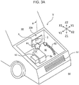
- Figs. 3A and 3B are a perspective view and a top view, respectively, conceptually illustrating a structure of a vehicle equipped with a vehicle speaker system according to a preferred example of the embodiment of the present invention.
- a shield member 3 is located so that an obstacle generation source (engine 51 and communication part 52) does not face an opening 2a.
- Such an arrangement of the shield member 3 can reliably prevent an obstacle (for example, heat 61 and foreign matter 62) emitted straight from the obstacle generation source (engine 51 and communication part 52) from reaching a speaker 1. Therefore, it is possible to more stably reduce the possibility that the obstacle (for example, heat 61 and foreign matter 62) from the obstacle generation source (engine 51 and communication part 52) will reach the speaker 1.
- an engine block 5b serving as a heat source is provided inside the engine-room inner space SE and the speaker 1 is located in the vehicle cabin inner space SR in a positional relationship illustrated in Figs. 3A and 3B .
- the engine block 5b is located at an angle ⁇ of several tens of degrees to a normal line NL to a surface (open surface) of the opening 2a on the side of the engine-room internal space SE.
- a member that constitutes the shield member 3 is disposed not only to cover the opening 2a but also to extend toward the engine block 5b (specifically, toward the Y2-side in the Y1-Y2 direction). Such an arrangement can more stably reduce the possibility that heat 61 from the engine block 5b will reach the speaker 1.
- the position of the speaker 1 relative to the partition 2 is fixed by mounting the frame 11 to the partition 2 with the mounting member 4 being disposed therebetween.
- the structure is not limited thereto.
- the position relative to the partition 2 may be fixed by directly mounting the frame 11 to the partition 2.
- the method for fixing the position of the shield member 3 relative to the partition 2 is also not limited.
- the shield member 3 is attached to the partition 2 by a support member 31 connected to the shield member 3.
- the structure as the vehicle speaker system 10 is simple and fixing is easy.
- the support member 31 has such a shape that the open part 7 is defined by the shield member 3, the partition 2, and the support member 31 when the support member 31 is attached to the partition 2. Since the support member 31 has such a structure, the open part 7 can be formed easily.
- Fig. 4 is a cross-sectional view conceptually illustrating a structure of a vehicle speaker system according to another embodiment of the present invention.
- a vehicle speaker system 10A includes a speaker unit 1U having a shield member 3 and a speaker 1.
- the speaker 1 is attached to an annular unit attachment member 8 beforehand with a mounting member 4 being disposed therebetween, and the shield member 3 is attached to the unit attachment member 8 together with a support member 31.
- the unit attachment member 8 of the speaker unit 1U is mounted on a partition 2.
- the speaker unit 1U can be mounted in the vehicle V from the side of a vehicle-cabin inner space SR (X1-side in the X1-X2 direction), mounting operability is further increased.
- the shield member 3 can be located inside the engine-room inner space SE by mounting the speaker unit 1U from the vehicle-cabin inner space SR (X1-side in the X1-X2 direction).
- FIG. 5 is a cross-sectional view conceptually illustrating a structure of a vehicle speaker system according to a further embodiment of the present invention.
- a vehicle speaker system 10B illustrated in Fig. 5 a mounting member 4 to which a speaker 1 is mounted is fixed to an inner wall of a cylindrical frame 9.
- the position of the speaker 1 relative to a partition 2 is fixed.
- the opening areas of an upper open portion 7a and a lower open portion 7b can be adjusted by changing the degree of insertion of the frame 9 in the opening 2a.
- a distal end of the frame 9 projects into an engine-room inner space SE.
- This projecting portion suppresses an obstacle from entering a first space S1 from directions other than the X1-X2 direction. Therefore, in the vehicle speaker system 10B, the possibility that an obstacle shielded by the shield member 3, especially, foreign matter 62 will enter the first space S1 through an open part 7 owing to, for example, scattering or rebounding is reduced.
- the shield member 3 and a support member 31 connected to the shield member 3 may be made of a material having a low thermal conductivity (for example, a heat-resistant resin material or a ceramic material having a low thermal conductivity).
- a low heat-transfer member made of a material having a low thermal conductivity may be interposed between the shield member 3 and the speaker 1. Specifically, it is only required that the mounting member 4 illustrated in Figs. 3A to 5 or the unit attachment member 8 illustrated in Fig. 4 should be a low heat-transfer member.
- FIG. 6 is a cross-sectional view conceptually illustrating a structure of a vehicle speaker system according to a still further embodiment of the present invention.
- a vehicle speaker system 10C illustrated in Fig. 6 has a structure in which a shield member 3 and a speaker 1 are not in direct contact with each other. Specifically, a support member 31 connected to the shield member 3 is not fixed to a partition 2, but is annexed to another member in an engine-room inner space SE. The position of the shield member 3 relative to the partition 2 is thereby fixed.
- an air current flowing from a lower open portion 7b to an upper open portion 7a is properly generated, and this can stably suppress heat received by the shield member 3 from being transmitted to the speaker 1.
- the speaker 1 may be located in any of the engine-room inner space SE and the vehicle-cabin inner space SR, and a part of the speaker 1 may be located in the engine-room inner space SE and the other part may be located in the vehicle-cabin inner space SR.
- the positional relationship between the opening 2a of the partition 2 and the speaker 1 is not limited.
- a reverse-phase sound pressure ejected from the speaker 1 to the engine-room inner space SE collides with the shield member 3, and is then stably diffused from the open part 7 of the first space S1 into the engine-room inner space SE. Therefore, it is sometimes preferable, from the viewpoint of maintaining the acoustic characteristics of the speaker 1, to adopt such a structure.
- the driving unit for the speaker 1 is the voice coil 16 in the above description, the structure is not limited thereto.
- the positional relationship between the diaphragm 12 and the driving unit in the speaker 1 may be arbitrarily determined.
- the diaphragm 12 in the speaker 1 may face the vehicle-cabin inner space SR, or conversely, may face the engine-room inner space SE.
- the diaphragm 12 of the speaker 1 faces the engine-room inner space SE as in the vehicle speaker systems 10, 10a, 10A, and 10B of the above embodiments, since the diaphragm 12 is susceptible to the influence of the obstacle (for example, heat 61 and foreign matter 62), the effect of using the shield member 3 as in the present invention can be more stably enjoyed.
Landscapes
- Engineering & Computer Science (AREA)
- Physics & Mathematics (AREA)
- Acoustics & Sound (AREA)
- Signal Processing (AREA)
- Mechanical Engineering (AREA)
- Fittings On The Vehicle Exterior For Carrying Loads, And Devices For Holding Or Mounting Articles (AREA)
- Details Of Audible-Bandwidth Transducers (AREA)
- Soundproofing, Sound Blocking, And Sound Damping (AREA)
Abstract
Description
- The present invention relates to a vehicle speaker system that allows stable operation of a speaker mounted in a partition between an engine-room inner space and a vehicle cabin.
- In speaker systems installed in vehicles (vehicle speaker systems), various methods for improving the quality of sound emitted in a vehicle cabin have been proposed. For example, in an on-vehicle composite speaker apparatus proposed in PTL 1 (Japanese Unexamined Utility Model Registration Application Publication No.
1-126679 - In the speaker apparatus disclosed in
PTL 1, the bass-sound auxiliary speaker is mounted with its back surface exposed in the engine room (Fig. 1 of PTL 1). However, multiple heat generation sources, such as an engine, are provided inside the engine room, and wind, rain, and dust may directly collide with the portion of the speaker exposed in the engine room (exposed portion) from the front side of the vehicle in a running state. In such a condition, reliability of the speaker is reduced and the speaker cannot exhibit its original performance (acoustic characteristics). Although it is conceivable to dispose, for example, a small enclosure behind the speaker for protection, a back pressure is insufficiently removed and this may adversely affect the acoustic characteristics. - The present invention has been made in view of these circumstances of the related art, and an object of the invention is to provide a vehicle speaker system including a speaker mounted on a vehicle partition, which separates an engine room and a vehicle cabin, and configured to emit a positive-phase sound pressure into the vehicle cabin and to exhaust a reverse-phase sound pressure to the engine room. In this vehicle speaker system, the speaker should preferably be prevented from being influenced by heat from the engine room and wind pressure associated with vehicle running, and a back pressure should sufficiently be removed to reduce the influence on the acoustic characteristics.
- The invention relates to a vehicle speaker system according to the appended claims. Embodiments are disclosed in the dependent claims.
- According to an aspect of the present invention, there is provided a vehicle speaker system including a speaker having a diaphragm that generates a sound pressure, a frame that supports the diaphragm vibratably, and a driving unit attached to the frame to drive the diaphragm. A position of the speaker relative to a partition separating a vehicle-cabin inner space and an engine-room inner space is determined so that the sound pressure generated by an action of the diaphragm passes through an opening provided in the partition. A shield member is provided with at least a part thereof being located between the speaker and an obstacle generation source located in the engine-room inner space to obstruct an operation of the speaker. An open part allowing a first space provided between the speaker and the shield member to communicate with the engine-room inner space is provided in such a direction as not to be directed toward the obstacle generation source.
- Specific examples of the obstacle generation source include an engine and a communication part in the engine-room inner space with a vehicle outer space. Heat generated from the engine, especially, an engine block may reach the speaker and deteriorate the members that constitute the speaker. Foreign matter, such as a pebble, may enter the engine-room inner space through the communication part and collide with the speaker. Such an obstacle (for example, heat and foreign matter) from the obstacle generation source obstructs a normal operation of the speaker. Accordingly, the adverse influence of the obstacle generation source on the speaker can be avoided by disposing the shield member between the speaker and the obstacle generation source. If the shield member forms a closed space between the shield member and the speaker, the acoustic characteristics of the speaker may be adversely affected. Accordingly, when the first space defined between the shield member and the speaker has the open part communicating with the engine-room inner space, the back pressure is smoothly removed, and this can reduce the influence on the acoustic characteristics of the speaker.
- In the above vehicle speaker system, preferably, the shield member is located to cover at least a center portion of the diaphragm. A section of the diaphragm near the center portion is most susceptible to the influence of wind pressure and heat. Hence, the speaker can be efficiently protected by covering the section.
- In the above vehicle speaker system, the shield member may be located inside the engine-room inner space and at least a part of the speaker may be located inside the vehicle-cabin inner space. When the shield member is located inside the engine-room inner space, an obstacle shielded by the shield member can be returned into the engine-room inner space. Moreover, gas inside the first space sometimes more easily moves than when the shield member is located in the vehicle-cabin inner space.
- In the above vehicle speaker system, the shield member may be shaped like a plate and may be located to cover the entire opening. In such a structure, an obstacle does not easily enter the vehicle-cabin inner space from the engine-room inner space. Therefore, the possibility that the obstacle from the obstacle generation source will reach the speaker is reduced more stably.
- In the above vehicle speaker system, preferably, the shield member is located at such a position that the obstacle generation source does not face the opening. When the shield member is disposed in this way, the obstacle emitted straight from the obstacle generation source can be reliably prevented from reaching the speaker. Therefore, the possibility that the obstacle from the obstacle generation source will reach the speaker can be more stably reduced.
- In the above vehicle speaker system, preferably, the open part includes a lower open portion into which a gas in the engine-room inner space flows and an upper open portion that allows a gas inside the first space to move upward and to be exhausted from the first space. When the obstacle is heat, the shield member is heated. Hence, the gas inside the first space is also heated. For this reason, an ascending air current is easily generated inside the first space. When the open part has the upper open portion, the heated gas in the first space is efficiently exhausted by the ascending air current, and this can suppress an excessive temperature rise in the first space. For this reason, the possibility that the speaker will be adversely affected by the heat is reduced more stably.
- In the above vehicle speaker system, a position of the speaker relative to the partition may be fixed by attaching the frame to the partition. While the method for fixing the position of the speaker relative to the partition is arbitrarily determined, when the frame of the speaker is attached to the partition, the structure as the vehicle speaker system is simple, and this sometimes makes fixing (attachment) easy. The frame of the speaker may be attached to the partition by a separate member (attachment member).
- In the above vehicle speaker system, the shield member may be attached to the partition by a support member connected to the shield member. While the method for fixing the position of the shield member relative to the speaker is arbitrarily determined, when the shield member is attached to the partition by the support member connected thereto, the structure as the speaker system is simple, and this sometimes makes fixing easy.
- In the above vehicle speaker system, a position of a speaker unit including the shield member and the speaker relative to the partition may be fixed. By preparing a unit (speaker unit) including the shield member and the speaker, the speaker is easily installed in the vehicle while the influence of the obstacle is properly reduced. When the speaker unit can be installed in the vehicle from the inner side of the vehicle cabin, installation operability is further enhanced. In this case, when the shield member is smaller than the opening provided in the partition, it can be located inside the engine-room inner space by installing the speaker unit from the inner side of the vehicle cabin.
- In the above vehicle speaker system, a low heat-transfer member may be interposed between the shield member and the speaker. When the low heat-transfer member is interposed between the shield member and the speaker, even if the temperature of the shield member is increased by heat received from, for example, the engine block, the possibility that the temperature of the speaker will be increased by heat transfer from the shield member can be reduced.
- The above vehicle speaker system may have a structure in which the shield member and the speaker are not in direct contact with each other. When the shield member and the speaker are not in direct contact with each other, even if the temperature of the shield member is increased by heat received from, for example, the engine block, the possibility that the temperature of the speaker will be increased by heat transfer from the shield member can be more stably reduced.
- In the above vehicle speaker system, preferably, the shield member is made of a conductive material and is groundable at least during use. Specific examples of obstacles include not only heat and foreign matter, but also an electromagnetic wave (electromagnetic noise) having a wavelength less than the wavelength of infrared light. When the driving unit for the speaker is a voice coil, driving stability is sometimes impaired by the influence of electromagnetic noise. When the shield member is made of a conductive material and is grounded during use, it also functions as an electromagnetic shield. Therefore, the operation stability of the speaker can be ensured even when the obstacle is the above-described electromagnetic noise.
- According to the vehicle speaker system of the present invention, the speaker can be prevented from being affected by heat from the engine room and wind pressure associated with vehicle running. Moreover, the back pressure is smoothly removed, and this can reduce the influence on the acoustic characteristics.
-
Figs. 1A and1B are a perspective view and a top view, respectively, conceptually illustrating a structure of a vehicle equipped with a vehicle speaker system according to an embodiment of the present invention; -
Fig. 2 is a cross-sectional view taken along line II-II inFig. 1A ; -
Figs. 3A and3B are a perspective view and a top view, respectively, conceptually illustrating a structure of a vehicle equipped with a vehicle speaker system according to a preferred example of the embodiment of the present invention; -
Fig. 4 is a cross-sectional view conceptually illustrating a structure of a vehicle speaker system according to another embodiment of the present invention; -
Fig. 5 is a cross-sectional view conceptually illustrating a structure of a vehicle speaker system according to a further embodiment of the present invention; and -
Fig. 6 is a cross-sectional view conceptually illustrating a structure of a vehicle speaker system according to a still further embodiment of the present invention. - Embodiments of the present invention will be described below with reference to the drawings.
Figs. 1A and1B are a perspective view and a top view, respectively, conceptually illustrating a structure of a vehicle quipped with a vehicle speaker system according to an embodiment of the present invention.Fig. 2 is a cross-sectional view taken along line II-II inFig. 1A . - As illustrated in
Fig. 2 , avehicle speaker system 10 according to an embodiment of the present invention includes aspeaker 1. In thespeaker 1, various members are attached to aframe 11 nearly shaped like a truncated cone. Theframe 11 includes anannular portion 11a on an outer peripheral side and a spoke-shapedsupport portion 11c extending from theannular portion 11a. For convenience, thesupport portion 11c is shown by dotted lines to have cutholes 11b in the drawings. - In the
speaker 1, adiaphragm 12 for generating sound pressure is nearly shaped like a truncated cone, and has anedge 12a on an outer peripheral side. Thisedge 12a is attached to theannular portion 11a of theframe 11. Specifically, in thespeaker 1 illustrated inFig. 2 , theedge 12a is bonded to theannular portion 11a of theframe 11 with adhesive. By thus being supported by theframe 11, thediaphragm 12 can vibrate in the front-rear direction of the frame 11 (X1-X2 direction inFig. 2 ). - The
diaphragm 12 has an opening (diaphragm opening) 12b in a center portion thereof. A bowl-shapedcap 13 is attached to thediaphragm 12 to close an inner peripheral portion of thediaphragm 12 including thediaphragm opening 12b. - A
magnetic circuit part 14 is attached to a top portion (magnetic-circuit attachment portion 11d) of the truncatedconical support portion 11c of theframe 11. Themagnetic circuit part 14 includes a columnarcenter pole portion 14a, and the center axis of thecenter pole portion 14a points in a vibrating direction of the diaphragm 12 (front-rear direction (X1-X2 direction)). Abottom plate portion 14b is provided integrally with a rear surrounding portion (X1-side in the X1-X2 direction) of thecenter pole portion 14a. Anannular magnet 14c is attached to a front side (X2-side in the X1-X2 direction) of thebottom plate portion 14b. An annulartop plate portion 14d is attached to a front side (X2-side in the X1-X2 direction) of themagnet 14c. Since themagnet 14c is provided, an annularmagnetic gap 14e is formed between thecenter pole portion 14a and thetop plate portion 14d. Thebottom plate portion 14b and thetop plate portion 14d constitute a yoke part. - A
cylindrical bobbin 15 is fixed to a rear side (X1-side in the X1-X2 direction) of thediaphragm 12. As illustrated inFig. 2 , thebobbin 15 is inserted in themagnetic gap 14e of themagnetic circuit part 14 located on the rear side of thediaphragm 12. Avoice coil 16 is wound around a side surface of a portion of thebobbin 15 inserted in themagnetic gap 14e. Thebobbin 15 reciprocates in the front-rear direction (X1-X2 direction) according to the current flowing through thevoice coil 16 located inside themagnetic gap 14e, so that thediaphragm 12 vibrates and generates sound pressure. - A
damper 17 is located between thediaphragm 12 and themagnetic circuit part 14 in the front-rear direction (X1-X2 direction). Thedamper 17 is supported on an outer peripheral side by thesupport portion 11c of theframe 11, and supports thebobbin 15 on an inner peripheral side. Along with the above-described reciprocating motion of thebobbin 15, not only thediaphragm 12 but also thedamper 17 reciprocates in the front-rear direction (X1-X2 direction). Thedamper 17 is constituted by an elastic member, and has a function of returning thebobbin 15 to a neutral position by an elastic restoring force in a state in which a current does not flow through thevoice coil 16. - In the
speaker 1 having the above-described structure, a positive-phase sound pressure can be emitted toward a vehicle-cabin inner space SR and a reverse-phase sound pressure can be ejected toward an engine-room inner space SE by passing a current through thevoice coil 16 to vibrate thediaphragm 12. - The
speaker 1 is mounted on apartition 2, which separates the vehicle-cabin inner space SR and the engine-room inner space SE, with a mountingmember 4. Thepartition 2 has anopening 2a. The position of thespeaker 1 relative to thepartition 2 is determined so that the sound pressure generated by the motion of thediaphragm 12 in thespeaker 1 passes through theopening 2a. - As illustrated in
Figs. 1A and1B , in the engine-room inner space SE of the vehicle V, an obstacle generation source that obstructs the operation of thespeaker 1 is located. In this specification, "obstacle generation source" refers to something that causes an obstacle for impairing stability of the operation of thespeaker 1 to exist in the engine-room inner space SE. InFigs. 1A and1B , anengine 51 and acommunication part 52 of the engine-room inner space SE with a vehicle outer space SX are illustrated as specific examples of the obstacle generation source.Heat 61 is generated as an obstacle from theengine 51, especially anengine block 5b. From thecommunication part 52,foreign matter 62, such as pebbles, rain, dust, and leaves, may enter the engine-room inner space SE as an obstacle and collide with thespeaker 1. Such an obstacle (for example,heat 61 and foreign matter 62) from the obstacle generation source (engine 51 and communication part 52) obstructs a normal operation of thespeaker 1. - Accordingly, in the
vehicle speaker system 10 according to the embodiment of the present invention, ashield member 3 is provided in such a manner that at least a part thereof is located between the obstacle generation source (engine 51 and communication part 52) in the engine-room inner space SE and thespeaker 1. By disposing theshield member 3 between thespeaker 1 and the obstacle generation source (engine 51 and communication part 52), an obstacle (for example,heat 61 and foreign matter 62) from the obstacle generation source (engine 51 and communication part 52) can be prevented from adversely affecting thespeaker 1. - The material of the
shield member 3 is arbitrarily determined as long as theshield member 3 can properly protect thespeaker 1 from the obstacle (for example,heat 61 and foreign matter 62). When theshield member 3 is made of a conductive material, it is grounded when thevehicle speaker system 10 is used. This allows thespeaker 1 to be protected from electromagnetic noise caused in the engine-room inner space SE. - Here, if a closed space is formed between the
shield member 3 and thespeaker 1, the back pressure is not sufficiently removed, and this may adversely affect the acoustic characteristics of thespeaker 1. Accordingly, in thevehicle speaker system 10 of this embodiment, a first space S1 has an open part 7 (an upperopen portion 7a and a loweropen portion 7b) communicating with the engine-room inner space SE. Formation of theopen part 7 can reduce the influence on the acoustic characteristics of thespeaker 1. - In the
vehicle speaker system 10 of this embodiment, theopen part 7 includes an upperopen portion 7a located at a relatively upper position (Z2-side in the Z1-Z2 direction) in the first space S1 and a loweropen portion 7b located at a relatively lower position (Z1-side in the Z1-Z2 direction). Since the upperopen portion 7a is provided, gas existing inside the first space S1 can move upward (toward the Z2-side in the Z1-Z2 direction) to be exhausted from the first space S1. Gas in the engine-room inner space SE is introduced from the loweropen portion 7b into the first space S1. - As illustrated in
Figs. 1A and1B , theengine 51 is located in the engine-room inner space SE, and in particular, a large amount ofheat 61 is emitted from theengine block 5b. The emittedheat 61 is prevented by theshield member 3 from directly reaching thespeaker 1, but is directly applied to theshield member 3. For this reason, the gas existing inside the first space S1 is heated. Hence, an ascending air current is easily generated inside the first space S1. When theopen part 7 has the upperopen portion 7a, the heated gas inside the first space S1 is efficiently exhausted by this ascending air current, and this can suppress an excessive temperature rise in the first space S1. For this reason, the possibility that thespeaker 1 will be adversely affected by the heat is more stably reduced. - In the
vehicle speaker system 10 of this embodiment, theshield member 3 is located inside the engine-room inner space SE. Since theshield member 3 is located inside the engine-room inner space SE, the obstacle shielded by theshield member 3 returns into the engine-room inner space SE. Moreover, the gas inside the first space S1 more easily moves and the temperature of thespeaker 1 is less likely to rise than when theshield member 3 is located in the vehicle-cabin inner space SR. Since the cut holes 11b of theframe 11 in thespeaker 1 are located inside the vehicle-cabin inner space SR, a positive-phase sound pressure from thespeaker 1 is properly emitted into the vehicle-cabin inner space SR. - While the
shield member 3 is shaped like a plate in thevehicle speaker system 10 of this embodiment, the shape of theshield member 3 is not limited thereto. The plate-shapedshield member 3 is advantageous in, for example, high workability. While the plate-shapedshield member 3 is located to cover theentire opening 2a of thepartition 2 in thevehicle speaker system 10 of the embodiment, the structure is not limited thereto. Theshield member 3 may cover a part (for example, a portion near a center portion) of theopening 2a of thepartition 2. When theshield member 3 covers theentire opening 2a of thepartition 2, the risk of entry of the obstacle from the engine-room inner space SE to the vehicle-cabin inner space SR is reduced more stably. -
Figs. 3A and3B are a perspective view and a top view, respectively, conceptually illustrating a structure of a vehicle equipped with a vehicle speaker system according to a preferred example of the embodiment of the present invention. In avehicle speaker system 10a illustrated inFigs. 3A and3B , as a preferred example, ashield member 3 is located so that an obstacle generation source (engine 51 and communication part 52) does not face anopening 2a. Such an arrangement of theshield member 3 can reliably prevent an obstacle (for example,heat 61 and foreign matter 62) emitted straight from the obstacle generation source (engine 51 and communication part 52) from reaching aspeaker 1. Therefore, it is possible to more stably reduce the possibility that the obstacle (for example,heat 61 and foreign matter 62) from the obstacle generation source (engine 51 and communication part 52) will reach thespeaker 1. - In the specific example, an
engine block 5b serving as a heat source is provided inside the engine-room inner space SE and thespeaker 1 is located in the vehicle cabin inner space SR in a positional relationship illustrated inFigs. 3A and3B . As illustrated inFig. 3B , theengine block 5b is located at an angle θ of several tens of degrees to a normal line NL to a surface (open surface) of theopening 2a on the side of the engine-room internal space SE. In this case, a member that constitutes theshield member 3 is disposed not only to cover theopening 2a but also to extend toward theengine block 5b (specifically, toward the Y2-side in the Y1-Y2 direction). Such an arrangement can more stably reduce the possibility that heat 61 from theengine block 5b will reach thespeaker 1. - In the
vehicle speaker systems speaker 1 relative to thepartition 2 is fixed by mounting theframe 11 to thepartition 2 with the mountingmember 4 being disposed therebetween. However, the structure is not limited thereto. The position relative to thepartition 2 may be fixed by directly mounting theframe 11 to thepartition 2. - The method for fixing the position of the
shield member 3 relative to thepartition 2 is also not limited. In thevehicle speaker systems shield member 3 is attached to thepartition 2 by asupport member 31 connected to theshield member 3. In this case, the structure as thevehicle speaker system 10 is simple and fixing is easy. Thesupport member 31 has such a shape that theopen part 7 is defined by theshield member 3, thepartition 2, and thesupport member 31 when thesupport member 31 is attached to thepartition 2. Since thesupport member 31 has such a structure, theopen part 7 can be formed easily. -
Fig. 4 is a cross-sectional view conceptually illustrating a structure of a vehicle speaker system according to another embodiment of the present invention. As illustrated inFig. 4 , avehicle speaker system 10A according to this embodiment includes aspeaker unit 1U having ashield member 3 and aspeaker 1. Specifically, thespeaker 1 is attached to an annularunit attachment member 8 beforehand with a mountingmember 4 being disposed therebetween, and theshield member 3 is attached to theunit attachment member 8 together with asupport member 31. Theunit attachment member 8 of thespeaker unit 1U is mounted on apartition 2. By thus preparing thespeaker unit 1U, thespeaker 1 is easily installed in a vehicle V while properly reducing the influence of an obstacle (for example,heat 61 and foreign matter 62) from an engine-room inner space SE. As long as thespeaker unit 1U can be mounted in the vehicle V from the side of a vehicle-cabin inner space SR (X1-side in the X1-X2 direction), mounting operability is further increased. Particularly when the outer diameter of theshield member 3 is smaller than the diameter of anopening 2a of thepartition 2, as illustrated inFig. 4 , theshield member 3 can be located inside the engine-room inner space SE by mounting thespeaker unit 1U from the vehicle-cabin inner space SR (X1-side in the X1-X2 direction). - When it is required to adjust the opening area of the
open part 7, a structure illustrated inFig. 5 may be adopted.Fig. 5 is a cross-sectional view conceptually illustrating a structure of a vehicle speaker system according to a further embodiment of the present invention. In avehicle speaker system 10B illustrated inFig. 5 , a mountingmember 4 to which aspeaker 1 is mounted is fixed to an inner wall of acylindrical frame 9. By inserting theframe 9 into anopening 2a, the position of thespeaker 1 relative to apartition 2 is fixed. Here, the opening areas of an upperopen portion 7a and a loweropen portion 7b can be adjusted by changing the degree of insertion of theframe 9 in theopening 2a. - In the
vehicle speaker system 10B having the structure ofFig. 5 , a distal end of theframe 9 projects into an engine-room inner space SE. This projecting portion suppresses an obstacle from entering a first space S1 from directions other than the X1-X2 direction. Therefore, in thevehicle speaker system 10B, the possibility that an obstacle shielded by theshield member 3, especially,foreign matter 62 will enter the first space S1 through anopen part 7 owing to, for example, scattering or rebounding is reduced. - Since a large amount of heat is emitted from an
engine block 5b in the engine-room inner space SE, it is preferable to take measures to further reduce the influence of the heat on thespeaker 1. For example, theshield member 3 and asupport member 31 connected to theshield member 3 may be made of a material having a low thermal conductivity (for example, a heat-resistant resin material or a ceramic material having a low thermal conductivity). A low heat-transfer member made of a material having a low thermal conductivity may be interposed between theshield member 3 and thespeaker 1. Specifically, it is only required that the mountingmember 4 illustrated inFigs. 3A to 5 or theunit attachment member 8 illustrated inFig. 4 should be a low heat-transfer member. - From the viewpoint of more stably avoiding the influence of heat from the engine-room inner space SE on the
speaker 1, a structure illustrated inFig. 6 may be adopted.Fig. 6 is a cross-sectional view conceptually illustrating a structure of a vehicle speaker system according to a still further embodiment of the present invention. Avehicle speaker system 10C illustrated inFig. 6 has a structure in which ashield member 3 and aspeaker 1 are not in direct contact with each other. Specifically, asupport member 31 connected to theshield member 3 is not fixed to apartition 2, but is annexed to another member in an engine-room inner space SE. The position of theshield member 3 relative to thepartition 2 is thereby fixed. In thevehicle speaker system 10C having such a structure, an air current flowing from a loweropen portion 7b to an upperopen portion 7a is properly generated, and this can stably suppress heat received by theshield member 3 from being transmitted to thespeaker 1. - While the embodiments and the application examples thereof have been described above, the present invention is not limited to these embodiments and examples. For example, for the embodiments and examples described above, addition, deletion, and design change of configuration elements and an appropriate combination of the features of the embodiments performed by those skilled in the art are within the scope of the present invention, as long as they include the subject matter of the present invention.
- For example, the
speaker 1 may be located in any of the engine-room inner space SE and the vehicle-cabin inner space SR, and a part of thespeaker 1 may be located in the engine-room inner space SE and the other part may be located in the vehicle-cabin inner space SR. The positional relationship between theopening 2a of thepartition 2 and thespeaker 1 is not limited. When thediaphragm 12 of thespeaker 1 is opposed to theopening 2a or when a part of thespeaker 1 is located in the engine-room inner space SE through theopening 2a, a reverse-phase sound pressure ejected from thespeaker 1 to the engine-room inner space SE collides with theshield member 3, and is then stably diffused from theopen part 7 of the first space S1 into the engine-room inner space SE. Therefore, it is sometimes preferable, from the viewpoint of maintaining the acoustic characteristics of thespeaker 1, to adopt such a structure. - While the driving unit for the
speaker 1 is thevoice coil 16 in the above description, the structure is not limited thereto. The positional relationship between thediaphragm 12 and the driving unit in thespeaker 1 may be arbitrarily determined. Thediaphragm 12 in thespeaker 1 may face the vehicle-cabin inner space SR, or conversely, may face the engine-room inner space SE. When thediaphragm 12 of thespeaker 1 faces the engine-room inner space SE as in thevehicle speaker systems diaphragm 12 is susceptible to the influence of the obstacle (for example,heat 61 and foreign matter 62), the effect of using theshield member 3 as in the present invention can be more stably enjoyed.
Claims (12)
- A vehicle speaker system comprising a speaker (1) including:a diaphragm (12) configured to generate a sound pressure;a frame (11) configured to support the diaphragm (12) vibratably; anda driving unit attached to the frame (11) to drive the diaphragm (12),the vehicle speaker system being characterized in that a position of the speaker (1) relative to a partition (2) separating a vehicle-cabin inner space (SR) and an engine-room inner space (SE) is such that the sound pressure generated by an action of the diaphragm (12) passes through an opening (2a) provided in the partition (2), and in that a shield member (3) is provided with at least a part thereof being located between the speaker (1) and an obstacle generation source (51, 52) located in the engine-room inner space (SE) to obstruct an operation of the speaker (1), and an open part (7) configured to allow a first space (S1) provided between the speaker (1) and the shield member (3) to communicate with the engine-room inner space (SE) is provided in such a direction as not to be directed toward the obstacle generation source (51, 52).
- The vehicle speaker system according to Claim 1, wherein the shield member (3) is located to cover at least a center portion of the diaphragm (12).
- The vehicle speaker system according to Claim 1 or 2, wherein the shield member (3) is located inside the engine-room inner space (SE).
- The vehicle speaker system according to any one of Claims 1 to 3, wherein the shield member (3) is shaped like a plate and is located to cover the entire opening (2a).
- The vehicle speaker system according to any one of Claims 1 to 4, wherein the shield member (3) is located at such a position that the obstacle generation source (51, 52) does not face the opening (2a).
- The vehicle speaker system according to any one of Claims 1 to 5, wherein the open part (7) includes a lower open portion (7b) into which a gas in the engine-room inner space (SE) flows and an upper open portion (7a) configured to allow a gas inside the first space (S1) to move upward and to be exhausted from the first space (S1).
- The vehicle speaker system according to any one of Claims 1 to 6, wherein the position of the speaker (1) relative to the partition (2) is fixed by attaching the frame (11) to the partition (2).
- The vehicle speaker system according to any one of Claims 1 to 7, wherein the shield member (3) is attached to the partition (2) by a support member (31) connected to the shield member (3).
- The vehicle speaker system according to any one of Claims 1 to 8, wherein a position of a speaker unit (1U) including the shield member (3) and the speaker (1) relative to the partition (2) is fixed.
- The vehicle speaker system according to any one of Claims 1 to 9, wherein a low heat-transfer member (8) is interposed between the shield member (3) and the speaker (1).
- The vehicle speaker system according to any one of Claims 1 to 8, wherein the shield member (3) and the speaker (1) are not in direct contact with each other.
- The vehicle speaker system according to any one of Claims 1 to 11, wherein the shield member (3) is made of a conductive material and is groundable at least during use.
Applications Claiming Priority (1)
| Application Number | Priority Date | Filing Date | Title |
|---|---|---|---|
| JP2017001112A JP6755627B2 (en) | 2017-01-06 | 2017-01-06 | Vehicle speaker system |
Publications (2)
| Publication Number | Publication Date |
|---|---|
| EP3346724A1 true EP3346724A1 (en) | 2018-07-11 |
| EP3346724B1 EP3346724B1 (en) | 2024-03-06 |
Family
ID=60915293
Family Applications (1)
| Application Number | Title | Priority Date | Filing Date |
|---|---|---|---|
| EP17209729.7A Active EP3346724B1 (en) | 2017-01-06 | 2017-12-21 | Vehicle speaker system |
Country Status (3)
| Country | Link |
|---|---|
| US (1) | US10358098B2 (en) |
| EP (1) | EP3346724B1 (en) |
| JP (1) | JP6755627B2 (en) |
Families Citing this family (3)
| Publication number | Priority date | Publication date | Assignee | Title |
|---|---|---|---|---|
| US12330566B2 (en) | 2019-08-06 | 2025-06-17 | Dr. Ing. H.C. F. Porsche Aktiengesellschaft | Pressure control in externally ducted loudspeakers |
| US11377041B2 (en) | 2019-08-06 | 2022-07-05 | Bose Corporation | Pressure control in externally ducted loudspeakers |
| EP4601319A1 (en) * | 2024-02-07 | 2025-08-13 | Alps Alpine Co., Ltd. | Vehicle loudspeaker system and vehicle structure comprising such loudspeaker system |
Citations (4)
| Publication number | Priority date | Publication date | Assignee | Title |
|---|---|---|---|---|
| US2233459A (en) * | 1937-05-29 | 1941-03-04 | Rca Corp | Acoustic apparatus for motor driven vehicles |
| JPH01126679U (en) | 1988-02-09 | 1989-08-30 | ||
| US20130272537A1 (en) * | 2012-04-17 | 2013-10-17 | Alpine Electronics, Inc. | Speaker |
| US20150030178A1 (en) * | 2012-02-24 | 2015-01-29 | Audi Ag | Loudspeaker system for a motor vehicle |
Family Cites Families (18)
| Publication number | Priority date | Publication date | Assignee | Title |
|---|---|---|---|---|
| US3045776A (en) * | 1958-04-16 | 1962-07-24 | Sony Kabushikihaisha | Speaker mounting device |
| DE2711126C3 (en) * | 1977-03-15 | 1981-05-14 | Blaupunkt-Werke Gmbh, 3200 Hildesheim | Device for attaching a loudspeaker |
| US4572326A (en) * | 1979-12-20 | 1986-02-25 | General Motors Corporation | Motor vehicle loudspeaker installation |
| JPS60226337A (en) * | 1984-04-22 | 1985-11-11 | Pioneer Electronic Corp | Car speaker device |
| JP2767746B2 (en) | 1987-11-12 | 1998-06-18 | 株式会社 タツノ・メカトロニクス | Display device |
| US5416283A (en) * | 1994-02-17 | 1995-05-16 | Adac Plastics, Inc. | Drop-in speaker mount |
| US6601645B1 (en) * | 2002-04-23 | 2003-08-05 | Nasser A. Abdo | Speaker heat sink |
| US7463746B2 (en) * | 2003-03-31 | 2008-12-09 | Bose Corporation | Narrow opening electroacoustical transducing |
| US20100148550A1 (en) * | 2008-12-11 | 2010-06-17 | Gm Global Technology Operations, Inc. | Audio headrest for attachment to a seat of a vehicle |
| US8804991B2 (en) * | 2009-10-23 | 2014-08-12 | Blueprint Acoustics Pty Ltd | Loudspeaker assembly and system |
| KR20120014293A (en) * | 2010-08-09 | 2012-02-17 | 현대로템 주식회사 | Loudspeaker cabin equipment |
| JP5967645B2 (en) * | 2012-01-24 | 2016-08-10 | アルパイン株式会社 | Installation structure of speaker device in vehicle |
| US9253562B2 (en) * | 2012-04-02 | 2016-02-02 | Bose Corporation | Vehicle loudspeaker module |
| DE102012109872B4 (en) * | 2012-10-16 | 2015-08-27 | Eberspächer Exhaust Technology GmbH & Co. KG | Speakers with improved thermal capacity |
| JP6177552B2 (en) * | 2013-03-15 | 2017-08-09 | アルパイン株式会社 | Speaker device |
| JPWO2015145549A1 (en) * | 2014-03-24 | 2017-04-13 | パイオニア株式会社 | Acoustic transducer for active noise control |
| US9872107B2 (en) * | 2015-01-16 | 2018-01-16 | Harman International Industries, Incorporated | Electrodynamic transducer with back cover for heat dissipation |
| JP6447193B2 (en) * | 2015-01-30 | 2019-01-09 | ヤマハ株式会社 | Speaker unit |
-
2017
- 2017-01-06 JP JP2017001112A patent/JP6755627B2/en active Active
- 2017-11-21 US US15/819,095 patent/US10358098B2/en active Active
- 2017-12-21 EP EP17209729.7A patent/EP3346724B1/en active Active
Patent Citations (4)
| Publication number | Priority date | Publication date | Assignee | Title |
|---|---|---|---|---|
| US2233459A (en) * | 1937-05-29 | 1941-03-04 | Rca Corp | Acoustic apparatus for motor driven vehicles |
| JPH01126679U (en) | 1988-02-09 | 1989-08-30 | ||
| US20150030178A1 (en) * | 2012-02-24 | 2015-01-29 | Audi Ag | Loudspeaker system for a motor vehicle |
| US20130272537A1 (en) * | 2012-04-17 | 2013-10-17 | Alpine Electronics, Inc. | Speaker |
Also Published As
| Publication number | Publication date |
|---|---|
| JP2018111328A (en) | 2018-07-19 |
| JP6755627B2 (en) | 2020-09-16 |
| EP3346724B1 (en) | 2024-03-06 |
| US20180194298A1 (en) | 2018-07-12 |
| US10358098B2 (en) | 2019-07-23 |
Similar Documents
| Publication | Publication Date | Title |
|---|---|---|
| CN110062304B (en) | Vehicle speaker | |
| EP2620328B1 (en) | Structure for installing loudspeaker system in vehicle | |
| JP5955079B2 (en) | Speaker device | |
| EP2779695B1 (en) | Loudspeaker unit | |
| JP2019531647A (en) | Loudspeaker system for vehicles | |
| EP3346724B1 (en) | Vehicle speaker system | |
| EP3249946B1 (en) | Vehicle loudspeaker system | |
| JP2022170165A (en) | Vibration generation device | |
| JP7258691B2 (en) | sound equipment | |
| KR20250151385A (en) | Loudspeaker modules, loudspeaker systems and vehicles | |
| KR101776773B1 (en) | Speaker assembly for vehicle, and vehicle having the same | |
| EP1509061A2 (en) | Speaker and method of installing the same | |
| EP4009658B1 (en) | In-vehicle sound emitting device | |
| EP4227937B1 (en) | Acoustic vehicle alerting system | |
| US11095974B1 (en) | External noise control for a loudspeaker | |
| JP2013236197A (en) | Electrodynamic sound emitting body | |
| EP4075828B1 (en) | Speaker | |
| US10405084B2 (en) | Loudspeaker with deflector at a port exit | |
| US20240236534A1 (en) | Speaker Device | |
| US20060198548A1 (en) | Frame for speaker device and speaker device | |
| JP7553338B2 (en) | In-vehicle sound device | |
| KR102288221B1 (en) | The side mirror assembly of a vehcle | |
| WO2009130778A1 (en) | Speaker system | |
| CN107295431A (en) | loudspeaker unit | |
| EP3086568B1 (en) | Vehicle sound system and related assembly |
Legal Events
| Date | Code | Title | Description |
|---|---|---|---|
| PUAI | Public reference made under article 153(3) epc to a published international application that has entered the european phase |
Free format text: ORIGINAL CODE: 0009012 |
|
| STAA | Information on the status of an ep patent application or granted ep patent |
Free format text: STATUS: THE APPLICATION HAS BEEN PUBLISHED |
|
| AK | Designated contracting states |
Kind code of ref document: A1 Designated state(s): AL AT BE BG CH CY CZ DE DK EE ES FI FR GB GR HR HU IE IS IT LI LT LU LV MC MK MT NL NO PL PT RO RS SE SI SK SM TR |
|
| AX | Request for extension of the european patent |
Extension state: BA ME |
|
| STAA | Information on the status of an ep patent application or granted ep patent |
Free format text: STATUS: REQUEST FOR EXAMINATION WAS MADE |
|
| 17P | Request for examination filed |
Effective date: 20190108 |
|
| RBV | Designated contracting states (corrected) |
Designated state(s): AL AT BE BG CH CY CZ DE DK EE ES FI FR GB GR HR HU IE IS IT LI LT LU LV MC MK MT NL NO PL PT RO RS SE SI SK SM TR |
|
| STAA | Information on the status of an ep patent application or granted ep patent |
Free format text: STATUS: EXAMINATION IS IN PROGRESS |
|
| 17Q | First examination report despatched |
Effective date: 20190731 |
|
| GRAP | Despatch of communication of intention to grant a patent |
Free format text: ORIGINAL CODE: EPIDOSNIGR1 |
|
| STAA | Information on the status of an ep patent application or granted ep patent |
Free format text: STATUS: GRANT OF PATENT IS INTENDED |
|
| INTG | Intention to grant announced |
Effective date: 20231026 |
|
| GRAS | Grant fee paid |
Free format text: ORIGINAL CODE: EPIDOSNIGR3 |
|
| GRAA | (expected) grant |
Free format text: ORIGINAL CODE: 0009210 |
|
| STAA | Information on the status of an ep patent application or granted ep patent |
Free format text: STATUS: THE PATENT HAS BEEN GRANTED |
|
| AK | Designated contracting states |
Kind code of ref document: B1 Designated state(s): AL AT BE BG CH CY CZ DE DK EE ES FI FR GB GR HR HU IE IS IT LI LT LU LV MC MK MT NL NO PL PT RO RS SE SI SK SM TR |
|
| REG | Reference to a national code |
Ref country code: GB Ref legal event code: FG4D |
|
| REG | Reference to a national code |
Ref country code: CH Ref legal event code: EP |
|
| REG | Reference to a national code |
Ref country code: DE Ref legal event code: R096 Ref document number: 602017079724 Country of ref document: DE |
|
| REG | Reference to a national code |
Ref country code: IE Ref legal event code: FG4D |
|
| P01 | Opt-out of the competence of the unified patent court (upc) registered |
Effective date: 20240301 |
|
| REG | Reference to a national code |
Ref country code: LT Ref legal event code: MG9D |
|
| PG25 | Lapsed in a contracting state [announced via postgrant information from national office to epo] |
Ref country code: LT Free format text: LAPSE BECAUSE OF FAILURE TO SUBMIT A TRANSLATION OF THE DESCRIPTION OR TO PAY THE FEE WITHIN THE PRESCRIBED TIME-LIMIT Effective date: 20240306 |
|
| REG | Reference to a national code |
Ref country code: NL Ref legal event code: MP Effective date: 20240306 |
|
| PG25 | Lapsed in a contracting state [announced via postgrant information from national office to epo] |
Ref country code: GR Free format text: LAPSE BECAUSE OF FAILURE TO SUBMIT A TRANSLATION OF THE DESCRIPTION OR TO PAY THE FEE WITHIN THE PRESCRIBED TIME-LIMIT Effective date: 20240607 |
|
| PG25 | Lapsed in a contracting state [announced via postgrant information from national office to epo] |
Ref country code: RS Free format text: LAPSE BECAUSE OF FAILURE TO SUBMIT A TRANSLATION OF THE DESCRIPTION OR TO PAY THE FEE WITHIN THE PRESCRIBED TIME-LIMIT Effective date: 20240606 Ref country code: HR Free format text: LAPSE BECAUSE OF FAILURE TO SUBMIT A TRANSLATION OF THE DESCRIPTION OR TO PAY THE FEE WITHIN THE PRESCRIBED TIME-LIMIT Effective date: 20240306 |
|
| PG25 | Lapsed in a contracting state [announced via postgrant information from national office to epo] |
Ref country code: ES Free format text: LAPSE BECAUSE OF FAILURE TO SUBMIT A TRANSLATION OF THE DESCRIPTION OR TO PAY THE FEE WITHIN THE PRESCRIBED TIME-LIMIT Effective date: 20240306 |
|
| PG25 | Lapsed in a contracting state [announced via postgrant information from national office to epo] |
Ref country code: RS Free format text: LAPSE BECAUSE OF FAILURE TO SUBMIT A TRANSLATION OF THE DESCRIPTION OR TO PAY THE FEE WITHIN THE PRESCRIBED TIME-LIMIT Effective date: 20240606 Ref country code: NO Free format text: LAPSE BECAUSE OF FAILURE TO SUBMIT A TRANSLATION OF THE DESCRIPTION OR TO PAY THE FEE WITHIN THE PRESCRIBED TIME-LIMIT Effective date: 20240606 Ref country code: LT Free format text: LAPSE BECAUSE OF FAILURE TO SUBMIT A TRANSLATION OF THE DESCRIPTION OR TO PAY THE FEE WITHIN THE PRESCRIBED TIME-LIMIT Effective date: 20240306 Ref country code: HR Free format text: LAPSE BECAUSE OF FAILURE TO SUBMIT A TRANSLATION OF THE DESCRIPTION OR TO PAY THE FEE WITHIN THE PRESCRIBED TIME-LIMIT Effective date: 20240306 Ref country code: GR Free format text: LAPSE BECAUSE OF FAILURE TO SUBMIT A TRANSLATION OF THE DESCRIPTION OR TO PAY THE FEE WITHIN THE PRESCRIBED TIME-LIMIT Effective date: 20240607 Ref country code: FI Free format text: LAPSE BECAUSE OF FAILURE TO SUBMIT A TRANSLATION OF THE DESCRIPTION OR TO PAY THE FEE WITHIN THE PRESCRIBED TIME-LIMIT Effective date: 20240306 Ref country code: ES Free format text: LAPSE BECAUSE OF FAILURE TO SUBMIT A TRANSLATION OF THE DESCRIPTION OR TO PAY THE FEE WITHIN THE PRESCRIBED TIME-LIMIT Effective date: 20240306 Ref country code: BG Free format text: LAPSE BECAUSE OF FAILURE TO SUBMIT A TRANSLATION OF THE DESCRIPTION OR TO PAY THE FEE WITHIN THE PRESCRIBED TIME-LIMIT Effective date: 20240306 |
|
| REG | Reference to a national code |
Ref country code: AT Ref legal event code: MK05 Ref document number: 1664699 Country of ref document: AT Kind code of ref document: T Effective date: 20240306 |
|
| PG25 | Lapsed in a contracting state [announced via postgrant information from national office to epo] |
Ref country code: SE Free format text: LAPSE BECAUSE OF FAILURE TO SUBMIT A TRANSLATION OF THE DESCRIPTION OR TO PAY THE FEE WITHIN THE PRESCRIBED TIME-LIMIT Effective date: 20240306 Ref country code: LV Free format text: LAPSE BECAUSE OF FAILURE TO SUBMIT A TRANSLATION OF THE DESCRIPTION OR TO PAY THE FEE WITHIN THE PRESCRIBED TIME-LIMIT Effective date: 20240306 |
|
| PG25 | Lapsed in a contracting state [announced via postgrant information from national office to epo] |
Ref country code: NL Free format text: LAPSE BECAUSE OF FAILURE TO SUBMIT A TRANSLATION OF THE DESCRIPTION OR TO PAY THE FEE WITHIN THE PRESCRIBED TIME-LIMIT Effective date: 20240306 |
|
| PG25 | Lapsed in a contracting state [announced via postgrant information from national office to epo] |
Ref country code: NL Free format text: LAPSE BECAUSE OF FAILURE TO SUBMIT A TRANSLATION OF THE DESCRIPTION OR TO PAY THE FEE WITHIN THE PRESCRIBED TIME-LIMIT Effective date: 20240306 |
|
| PG25 | Lapsed in a contracting state [announced via postgrant information from national office to epo] |
Ref country code: IS Free format text: LAPSE BECAUSE OF FAILURE TO SUBMIT A TRANSLATION OF THE DESCRIPTION OR TO PAY THE FEE WITHIN THE PRESCRIBED TIME-LIMIT Effective date: 20240706 |
|
| PG25 | Lapsed in a contracting state [announced via postgrant information from national office to epo] |
Ref country code: SM Free format text: LAPSE BECAUSE OF FAILURE TO SUBMIT A TRANSLATION OF THE DESCRIPTION OR TO PAY THE FEE WITHIN THE PRESCRIBED TIME-LIMIT Effective date: 20240306 Ref country code: PT Free format text: LAPSE BECAUSE OF FAILURE TO SUBMIT A TRANSLATION OF THE DESCRIPTION OR TO PAY THE FEE WITHIN THE PRESCRIBED TIME-LIMIT Effective date: 20240708 |
|
| PG25 | Lapsed in a contracting state [announced via postgrant information from national office to epo] |
Ref country code: CZ Free format text: LAPSE BECAUSE OF FAILURE TO SUBMIT A TRANSLATION OF THE DESCRIPTION OR TO PAY THE FEE WITHIN THE PRESCRIBED TIME-LIMIT Effective date: 20240306 Ref country code: EE Free format text: LAPSE BECAUSE OF FAILURE TO SUBMIT A TRANSLATION OF THE DESCRIPTION OR TO PAY THE FEE WITHIN THE PRESCRIBED TIME-LIMIT Effective date: 20240306 |
|
| PG25 | Lapsed in a contracting state [announced via postgrant information from national office to epo] |
Ref country code: AT Free format text: LAPSE BECAUSE OF FAILURE TO SUBMIT A TRANSLATION OF THE DESCRIPTION OR TO PAY THE FEE WITHIN THE PRESCRIBED TIME-LIMIT Effective date: 20240306 |
|
| PG25 | Lapsed in a contracting state [announced via postgrant information from national office to epo] |
Ref country code: PL Free format text: LAPSE BECAUSE OF FAILURE TO SUBMIT A TRANSLATION OF THE DESCRIPTION OR TO PAY THE FEE WITHIN THE PRESCRIBED TIME-LIMIT Effective date: 20240306 |
|
| PG25 | Lapsed in a contracting state [announced via postgrant information from national office to epo] |
Ref country code: SK Free format text: LAPSE BECAUSE OF FAILURE TO SUBMIT A TRANSLATION OF THE DESCRIPTION OR TO PAY THE FEE WITHIN THE PRESCRIBED TIME-LIMIT Effective date: 20240306 |
|
| PG25 | Lapsed in a contracting state [announced via postgrant information from national office to epo] |
Ref country code: SM Free format text: LAPSE BECAUSE OF FAILURE TO SUBMIT A TRANSLATION OF THE DESCRIPTION OR TO PAY THE FEE WITHIN THE PRESCRIBED TIME-LIMIT Effective date: 20240306 Ref country code: SK Free format text: LAPSE BECAUSE OF FAILURE TO SUBMIT A TRANSLATION OF THE DESCRIPTION OR TO PAY THE FEE WITHIN THE PRESCRIBED TIME-LIMIT Effective date: 20240306 Ref country code: RO Free format text: LAPSE BECAUSE OF FAILURE TO SUBMIT A TRANSLATION OF THE DESCRIPTION OR TO PAY THE FEE WITHIN THE PRESCRIBED TIME-LIMIT Effective date: 20240306 Ref country code: PT Free format text: LAPSE BECAUSE OF FAILURE TO SUBMIT A TRANSLATION OF THE DESCRIPTION OR TO PAY THE FEE WITHIN THE PRESCRIBED TIME-LIMIT Effective date: 20240708 Ref country code: PL Free format text: LAPSE BECAUSE OF FAILURE TO SUBMIT A TRANSLATION OF THE DESCRIPTION OR TO PAY THE FEE WITHIN THE PRESCRIBED TIME-LIMIT Effective date: 20240306 Ref country code: IS Free format text: LAPSE BECAUSE OF FAILURE TO SUBMIT A TRANSLATION OF THE DESCRIPTION OR TO PAY THE FEE WITHIN THE PRESCRIBED TIME-LIMIT Effective date: 20240706 Ref country code: EE Free format text: LAPSE BECAUSE OF FAILURE TO SUBMIT A TRANSLATION OF THE DESCRIPTION OR TO PAY THE FEE WITHIN THE PRESCRIBED TIME-LIMIT Effective date: 20240306 Ref country code: CZ Free format text: LAPSE BECAUSE OF FAILURE TO SUBMIT A TRANSLATION OF THE DESCRIPTION OR TO PAY THE FEE WITHIN THE PRESCRIBED TIME-LIMIT Effective date: 20240306 Ref country code: AT Free format text: LAPSE BECAUSE OF FAILURE TO SUBMIT A TRANSLATION OF THE DESCRIPTION OR TO PAY THE FEE WITHIN THE PRESCRIBED TIME-LIMIT Effective date: 20240306 |
|
| PG25 | Lapsed in a contracting state [announced via postgrant information from national office to epo] |
Ref country code: IT Free format text: LAPSE BECAUSE OF FAILURE TO SUBMIT A TRANSLATION OF THE DESCRIPTION OR TO PAY THE FEE WITHIN THE PRESCRIBED TIME-LIMIT Effective date: 20240306 |
|
| REG | Reference to a national code |
Ref country code: DE Ref legal event code: R097 Ref document number: 602017079724 Country of ref document: DE |
|
| PG25 | Lapsed in a contracting state [announced via postgrant information from national office to epo] |
Ref country code: IT Free format text: LAPSE BECAUSE OF FAILURE TO SUBMIT A TRANSLATION OF THE DESCRIPTION OR TO PAY THE FEE WITHIN THE PRESCRIBED TIME-LIMIT Effective date: 20240306 |
|
| PLBE | No opposition filed within time limit |
Free format text: ORIGINAL CODE: 0009261 |
|
| STAA | Information on the status of an ep patent application or granted ep patent |
Free format text: STATUS: NO OPPOSITION FILED WITHIN TIME LIMIT |
|
| PG25 | Lapsed in a contracting state [announced via postgrant information from national office to epo] |
Ref country code: DK Free format text: LAPSE BECAUSE OF FAILURE TO SUBMIT A TRANSLATION OF THE DESCRIPTION OR TO PAY THE FEE WITHIN THE PRESCRIBED TIME-LIMIT Effective date: 20240306 |
|
| PG25 | Lapsed in a contracting state [announced via postgrant information from national office to epo] |
Ref country code: DK Free format text: LAPSE BECAUSE OF FAILURE TO SUBMIT A TRANSLATION OF THE DESCRIPTION OR TO PAY THE FEE WITHIN THE PRESCRIBED TIME-LIMIT Effective date: 20240306 |
|
| 26N | No opposition filed |
Effective date: 20241209 |
|
| PG25 | Lapsed in a contracting state [announced via postgrant information from national office to epo] |
Ref country code: SI Free format text: LAPSE BECAUSE OF FAILURE TO SUBMIT A TRANSLATION OF THE DESCRIPTION OR TO PAY THE FEE WITHIN THE PRESCRIBED TIME-LIMIT Effective date: 20240306 |
|
| PG25 | Lapsed in a contracting state [announced via postgrant information from national office to epo] |
Ref country code: MC Free format text: LAPSE BECAUSE OF FAILURE TO SUBMIT A TRANSLATION OF THE DESCRIPTION OR TO PAY THE FEE WITHIN THE PRESCRIBED TIME-LIMIT Effective date: 20240306 |
|
| REG | Reference to a national code |
Ref country code: CH Ref legal event code: PL |
|
| PG25 | Lapsed in a contracting state [announced via postgrant information from national office to epo] |
Ref country code: LU Free format text: LAPSE BECAUSE OF NON-PAYMENT OF DUE FEES Effective date: 20241221 |
|
| REG | Reference to a national code |
Ref country code: BE Ref legal event code: MM Effective date: 20241231 |
|
| PG25 | Lapsed in a contracting state [announced via postgrant information from national office to epo] |
Ref country code: BE Free format text: LAPSE BECAUSE OF NON-PAYMENT OF DUE FEES Effective date: 20241231 |
|
| PG25 | Lapsed in a contracting state [announced via postgrant information from national office to epo] |
Ref country code: CH Free format text: LAPSE BECAUSE OF NON-PAYMENT OF DUE FEES Effective date: 20241231 |
|
| PG25 | Lapsed in a contracting state [announced via postgrant information from national office to epo] |
Ref country code: IE Free format text: LAPSE BECAUSE OF NON-PAYMENT OF DUE FEES Effective date: 20241221 |
|
| PGFP | Annual fee paid to national office [announced via postgrant information from national office to epo] |
Ref country code: DE Payment date: 20251211 Year of fee payment: 9 |
|
| PGFP | Annual fee paid to national office [announced via postgrant information from national office to epo] |
Ref country code: GB Payment date: 20251219 Year of fee payment: 9 |
|
| PGFP | Annual fee paid to national office [announced via postgrant information from national office to epo] |
Ref country code: FR Payment date: 20251229 Year of fee payment: 9 |
|
| PG25 | Lapsed in a contracting state [announced via postgrant information from national office to epo] |
Ref country code: CY Free format text: LAPSE BECAUSE OF FAILURE TO SUBMIT A TRANSLATION OF THE DESCRIPTION OR TO PAY THE FEE WITHIN THE PRESCRIBED TIME-LIMIT Effective date: 20240306 |