EP3346699A1 - Projection device, projection method and program storage medium - Google Patents
Projection device, projection method and program storage medium Download PDFInfo
- Publication number
- EP3346699A1 EP3346699A1 EP16841129.6A EP16841129A EP3346699A1 EP 3346699 A1 EP3346699 A1 EP 3346699A1 EP 16841129 A EP16841129 A EP 16841129A EP 3346699 A1 EP3346699 A1 EP 3346699A1
- Authority
- EP
- European Patent Office
- Prior art keywords
- image
- projection
- distortion
- displayed
- projection surface
- Prior art date
- Legal status (The legal status is an assumption and is not a legal conclusion. Google has not performed a legal analysis and makes no representation as to the accuracy of the status listed.)
- Granted
Links
Images







Classifications
-
- G—PHYSICS
- G06—COMPUTING OR CALCULATING; COUNTING
- G06T—IMAGE DATA PROCESSING OR GENERATION, IN GENERAL
- G06T3/00—Geometric image transformations in the plane of the image
- G06T3/08—Projecting images onto non-planar surfaces, e.g. geodetic screens
-
- H—ELECTRICITY
- H04—ELECTRIC COMMUNICATION TECHNIQUE
- H04N—PICTORIAL COMMUNICATION, e.g. TELEVISION
- H04N9/00—Details of colour television systems
- H04N9/12—Picture reproducers
- H04N9/31—Projection devices for colour picture display, e.g. using electronic spatial light modulators [ESLM]
- H04N9/3179—Video signal processing therefor
- H04N9/3185—Geometric adjustment, e.g. keystone or convergence
-
- G—PHYSICS
- G03—PHOTOGRAPHY; CINEMATOGRAPHY; ANALOGOUS TECHNIQUES USING WAVES OTHER THAN OPTICAL WAVES; ELECTROGRAPHY; HOLOGRAPHY
- G03B—APPARATUS OR ARRANGEMENTS FOR TAKING PHOTOGRAPHS OR FOR PROJECTING OR VIEWING THEM; APPARATUS OR ARRANGEMENTS EMPLOYING ANALOGOUS TECHNIQUES USING WAVES OTHER THAN OPTICAL WAVES; ACCESSORIES THEREFOR
- G03B21/00—Projectors or projection-type viewers; Accessories therefor
-
- G—PHYSICS
- G03—PHOTOGRAPHY; CINEMATOGRAPHY; ANALOGOUS TECHNIQUES USING WAVES OTHER THAN OPTICAL WAVES; ELECTROGRAPHY; HOLOGRAPHY
- G03B—APPARATUS OR ARRANGEMENTS FOR TAKING PHOTOGRAPHS OR FOR PROJECTING OR VIEWING THEM; APPARATUS OR ARRANGEMENTS EMPLOYING ANALOGOUS TECHNIQUES USING WAVES OTHER THAN OPTICAL WAVES; ACCESSORIES THEREFOR
- G03B21/00—Projectors or projection-type viewers; Accessories therefor
- G03B21/14—Details
-
- G—PHYSICS
- G06—COMPUTING OR CALCULATING; COUNTING
- G06T—IMAGE DATA PROCESSING OR GENERATION, IN GENERAL
- G06T5/00—Image enhancement or restoration
- G06T5/20—Image enhancement or restoration using local operators
-
- G—PHYSICS
- G06—COMPUTING OR CALCULATING; COUNTING
- G06T—IMAGE DATA PROCESSING OR GENERATION, IN GENERAL
- G06T5/00—Image enhancement or restoration
- G06T5/80—Geometric correction
-
- G—PHYSICS
- G06—COMPUTING OR CALCULATING; COUNTING
- G06T—IMAGE DATA PROCESSING OR GENERATION, IN GENERAL
- G06T7/00—Image analysis
- G06T7/0002—Inspection of images, e.g. flaw detection
-
- H—ELECTRICITY
- H04—ELECTRIC COMMUNICATION TECHNIQUE
- H04N—PICTORIAL COMMUNICATION, e.g. TELEVISION
- H04N9/00—Details of colour television systems
- H04N9/12—Picture reproducers
- H04N9/31—Projection devices for colour picture display, e.g. using electronic spatial light modulators [ESLM]
- H04N9/3191—Testing thereof
- H04N9/3194—Testing thereof including sensor feedback
-
- G—PHYSICS
- G06—COMPUTING OR CALCULATING; COUNTING
- G06T—IMAGE DATA PROCESSING OR GENERATION, IN GENERAL
- G06T2207/00—Indexing scheme for image analysis or image enhancement
- G06T2207/30—Subject of image; Context of image processing
- G06T2207/30168—Image quality inspection
Definitions
- the present invention relates to a projection device, a projection method, and a projection program.
- the present invention relates to a projection device, a projection method, and a projection program for projecting an image on a projection surface having unevenness.
- a general projector is manufactured based on a premise that an image is projected on a flat wall surface.
- an image to be projected on a wall surface may be distorted depending on a positional relationship between the projector and the wall surface.
- a projecting direction is not straight with respect to a wall surface
- an image may be projected with different magnification ratios between a vertical direction and a horizontal direction.
- PTL 1 discloses an example of keystone correction.
- PTLs 2 and 3 disclose devices for capturing a projected image and adjusting the projected image, based on a captured pattern.
- PTL 4 discloses a technique for correcting distortion of a displayed image even on a surface having unevenness or a projection surface of a curved surface.
- a device in PTL 4 it is possible to project an image even on a projection surface having unevenness or a curved surface by approximating a projection surface having unevenness to an imaginary flat projection surface, or by capturing a specific projected pattern by a camera and measuring a distance by using a principle of triangulation.
- a principle of triangulation there is a problem that it takes time for distance measurement, since a distance is measured by using a principle of triangulation.
- some unevenness may be overlooked, when an uneven surface is complicated, since the device can measure only a distance to a position where a pattern is projected.
- An object of the present invention is to provide a projection device that enables to display an image even on a projection surface having complex unevenness, as well as on a flat surface.
- a projection device includes: a storage unit that stores at least a pattern image for detecting distortion depending on a surface state of a projection surface, an expected image associated with a displayed image when the pattern image is displayed on a flat surface, and a desired projection image; a projection unit that projects, on the projection surface, an image including the pattern image and the desired projection image; an image acquisition unit that acquires a displayed image of the pattern image displayed on the projection surface, and extracts a distortion image; a distortion amount calculating unit that calculates a distortion parameter relating to distortion of the projection surface by comparing the expected image with the distortion image; a distortion correction processing unit that corrects the desired projection image to be projected on the projection surface, by using the distortion parameter; and an image output unit that outputs, to the projection unit, image data including the desired projection image corrected by the distortion correction processing unit, and the pattern image.
- a projection method includes: projecting a pattern image for detecting distortion depending on a surface state of a projection surface, on the projection surface; acquiring a displayed image of the pattern image displayed on the projection surface, and extracting a distortion image; calculating a distortion parameter of the projection surface, by comparing an expected image associated with a displayed image when the pattern image is displayed on a flat surface, with the distortion image; correcting a desired projection image to be projected on the projection surface, by using the distortion parameter; and projecting the corrected desired projection image, on the projection surface.
- a projection program causes a computer to execute: processing of projecting a pattern image for detecting distortion depending on a surface state of a projection surface, on the projections surface; processing of acquiring a displayed image of the pattern image displayed on the projection surface, and extracting a distortion image; processing of calculating a distortion parameter of the projection surface by comparing an expected image associated with a displayed image when the pattern image is displayed on a flat surface, with the distortion image; processing of correcting a desired projection image to be projected on the projection surface, by using the distortion parameter; and processing of projecting the corrected desired projection image on the projection surface.
- the present invention it is possible to provide a projection device that enables to display an image even on a projection surface having complex unevenness, as well as on a flat surface.
- Fig. 1 is a block diagram illustrating a configuration of the projection device 10 according to the present example embodiment.
- Fig. 2 is a conceptual diagram for describing a flow of data between constituent elements of the projection device 10 according to the present example embodiment.
- the projection device 10 includes a storage unit 11, an image output unit 12, a projection unit 13, an image acquisition unit 14, a distortion amount calculating unit 15, and a distortion correction processing unit 16. Further, the projection device 10 is configured to acquire image data captured by a camera 20. Note that the projection device 10 may include the camera 20 (imaging means).
- the storage unit 11 stores various image data.
- the storage unit 11 stores at least a pattern image (pattern image 120) for detecting distortion depending on a surface state of a projection surface, an expected image (expected image 150) associated with a displayed image when the pattern image is displayed on a flat surface, and a desired projection image (projection image 160). Further, the storage unit 11 may also be configured to store a distortion image 140 corresponding to a displayed image of the pattern image 120 displayed on a projection surface, and a distortion parameter.
- the image output unit 12 outputs, to the projection unit 13, image data such as the pattern image 120 and the projection image 160 subjected to distortion correction. Specifically, the image output unit 12 outputs, to the projection unit 13, image data including the projection image 160 corrected by the distortion correction processing unit 16, and the pattern image 120.
- the projection unit 13 projects image data output from the image output unit 12. Specifically, the projection unit 13 projects an image including the pattern image 120 and the projection image 160 on a projection surface.
- the projection unit 13 may be configured by a general projector.
- the image acquisition unit 14 acquires image data captured by the camera 20.
- the image acquisition unit 14 extracts, from the acquired image data, a displayed image of the pattern image 120 (hereinafter, distortion image 140). Specifically, the image acquisition unit 14 acquires the distortion image 140 corresponding to a displayed image of the pattern image 120 displayed on a projection surface.
- the distortion amount calculating unit 15 calculates a distortion amount (also referred to as a distortion parameter) of a projection surface by comparting the distortion image 140 with the expected image 150.
- the distortion correction processing unit 16 performs distortion correction in such a manner that the desired projection image 160 is displayed on a projection surface, by using the distortion amount calculated by the distortion amount calculating unit 15. Specifically, the distortion correction processing unit 16 corrects the projection image 160 to be projected on a projection surface, by using the distortion amount calculated by the distortion amount calculating unit 15.
- the camera 20 is connected to the projection device 10.
- the camera 20 captures a projection surface, and outputs the captured image data to the image acquisition unit 14.
- the camera 20 may be configured by a general camera.
- Fig. 3 to Fig. 6 are conceptual diagrams for describing calibration in the present example embodiment (hereinafter, main calibration).
- an image is displayed on a projection surface having unevenness with same quality as when the image is projected on a flat surface, by calculating a moving amount (distortion) of the image due to unevenness on the projection surface for each area, when the image is projected on the projection surface having unevenness.
- Fig. 3 illustrates an example of a displayed image 101 to be displayed when the pattern image 120 constituted by a plurality of triangles is projected on an uneven surface 100.
- the image acquisition unit 14 extracts the distortion image 140 from the displayed image 101.
- numerals indicated within some triangles denote numbers given to these triangles. Note that a part of the pattern image 120 may be projected successively, or the entirety of the pattern image 120 may be displayed all at once.
- a size of a triangle constituting the pattern image may be changed depending on a size of unevenness. For example, on a projection surface having large unevenness, a triangle constituting the pattern image 120 is made small. Making a triangle smaller enhances image quality better, since correction accuracy is more enhanced. Further, for example, on a projection surface having small unevenness, a triangle constituting the pattern image 120 is made large. Making a triangle larger enables time required for calibration to be shorter.
- the camera 20 captures the uneven surface 100.
- the displayed image 101 displayed on the uneven surface 100 includes distortion depending on a state of the uneven surface 100.
- Fig. 4 illustrates an example of an expected image 201 which is expected to be displayed when the pattern image 120 is projected on a flat surface 200.
- the expected image 201 in Fig. 4 may be stored in advance in the storage unit 11, and is not required to be actually displayed.
- numerals indicated within some triangles denote numbers given to these triangles.
- a triangle in Fig. 3 and a triangle in Fig. 4 to which same numbers are given are triangles associated with each other.
- a difference in shape or position between these triangles is reflected on a distortion amount.
- a distortion amount increases, as a difference in shape or position between triangles associated with each other in Fig. 3 and Fig. 4 increases.
- Fig. 5 is an example in which the displayed image 101 (corresponding to a distortion image) and the expected image 201 are compared.
- the displayed image 101 and the expected image 201 are compared for each triangle.
- a triangle abc on the upper left of the displayed image 101 is compared with a triangle ABC of the expected image 201.
- a moving amount 205 between the triangle abc and the triangle ABC is calculated, and an inverse matrix (distortion parameter) is calculated from the moving amount 205 for each triangle.
- the distortion amount calculating unit 15 calculates, as a distortion parameter, an inverse matrix of a matrix for transforming the triangle abc constituting the displayed image 101 (distortion image) to the triangle ABC constituting the expected image 201.
- the distortion correction processing unit 16 corrects distortion of the projection image 160 to be displayed on a projection surface, by using the inverse matrix to be calculated herein.
- Fig. 6 is an example in which the projection image 160 subjected to distortion correction is displayed on the uneven surface 100.
- projecting an image to be projected from the projection device 10 by distorting the image in advance with use of a distortion parameter enables to display an image without distortion even when the image is projected on the uneven surface 100.
- by performing distortion correction in advance with respect to a projection image, which may be distorted when being projected on the uneven surface 100 as it is, as illustrated in Fig. 6 the projection image 160 is displayed on the uneven surface 100 as if the image is projected on a flat surface.
- FIG. 7 is a flowchart illustrating an operation of the projection device 10 according to the present example embodiment.
- the image output unit 12 acquires the pattern image 120 from the storage unit 11, and outputs the acquired pattern image 120.
- the projection unit 13 projects the pattern image 120 output by the image output unit 12 (Step S11).
- the pattern image 120 projected from the projection unit 13 is displayed on a projection surface.
- the camera 20 captures the displayed image 101 displayed on the projection surface.
- the image acquisition unit 14 acquires the displayed image 101 captured by the camera, and extracts the distortion image 140 from the acquired displayed image 101 (Step S12).
- the image acquisition unit 14 outputs the extracted distortion image 140 to the distortion amount calculating unit 15.
- the distortion amount calculating unit 15 acquires the distortion image 140 from the image acquisition unit 14, and also acquires the expected image 150 from the storage unit 11. Then, the distortion amount calculating unit 15 calculates a distortion parameter by comparing the distortion image 140 with the expected image 150 (Step S13).
- Step S14 when there remains a triangle to be calibrated among triangles constituting the pattern image, and calibration is continued (Yes in Step S14), the flow returns to Step S11. On the other hand, when the calibration is finished (No in Step S14), the flow proceeds to Step S15.
- the distortion correction processing unit 16 acquires a distortion parameter from the distortion amount calculating unit 15.
- the distortion correction processing unit 16 acquires the desired projection image 160 from the storage unit 11, and corrects the projection image 160 by using the distortion parameter (Step S15).
- the image output unit 12 outputs the corrected projection image 160 to the projection unit 13.
- the projection unit 13 projects the corrected projection image 160 (Step S16).
- Fig. 8 is an example in which a displayed image 104 is displayed on an uneven surface 103.
- the displayed image 104 is displayed successively by projecting cross-shaped patterns on the uneven surface 103 in the order of a, b, c, d, e, ..., and a distortion parameter is calculated for each triangle to be formed by three vertexes.
- the projection device 10 projects the patterns a, b, and c successively on the uneven surface 103.
- the projected cross-shaped patterns form a triangle abc.
- the camera 20 captures the uneven surface 103, and feeds back the triangle abc to the projection device 10. In this stage, only the triangle abc included in the displayed image 104 is acquired.
- the distortion amount calculating unit 15 calculates an inverse matrix T -1 by using a relationship expressed by the following Equation (1) with use of the acquired triangle abc and a triangle ABC of an expected image 105.
- the inverse matrix T -1 is an inverse matrix of a transformation matrix T for transforming the triangle abc to the triangle ABC depending on a local state of the uneven surface 103, and corresponds to a distortion parameter.
- the triangle abc and the triangle ABC in Equation (1) are normally expressed by a two-dimensional coordinate system, but may be expressed by a three-dimensional coordinate system.
- a size or a component of the transformation matrix T is set in association with a coordinate system or a transformation condition of the triangle abc and the triangle ABC.
- the projection device 10 projects patterns d, e, ..., successively, and obtains an inverse matrix (distortion parameter) in the order of a triangle bcd, a triangle cde, .... Specifically, the projection device 10 compares triangles included in the displayed image 104 and the expected image 105 and having a correlation, and calculates a distortion parameter for each triangle to be formed by a projection pattern. As a result of the calculation, the projection device 10 is able to obtain a distortion parameter depending on a local state of the uneven surface 103.
- the distortion correction processing unit 16 corrects a projection image 106 by using a distortion parameter for each triangle.
- the distortion correction processing unit 16 calculates a reference pixel position of the projection image 106 by applying an inverse matrix (distortion parameter) to the distortion corrected image 107.
- the distortion correction processing unit 16 may calculate a reference pixel position of the projection image 106 for each pixel of the distortion corrected image 107.
- the distortion correction processing unit 16 calculates a reference pixel position of the projection image 106 for each triangle to be defined on the distortion corrected image 107. In this case, the distortion correction processing unit 16 completes an image needed to be displayed on the uneven surface 103 by calculating a reference pixel position of the projection image 106 with respect to an entire area of the distortion corrected image 107. Note that the distortion correction processing unit 16 may calculate a reference pixel position of the projection image 106 in a stage when a distortion parameter is calculated for all triangles defined on the distortion corrected image 107.
- the present example embodiment it is possible to enhance correction accuracy and to enhance image quality by reducing a size of a triangle constituting a pattern image on a projection surface having large unevenness. Further, according to the present example embodiment, it is possible to shorten time required for calibration by increasing a size of a triangle constituting a pattern image on a projection surface having small unevenness.
- a layout example of the camera 20 is illustrated ( Fig. 11 ).
- the camera 20 is disposed according to viewpoints of audiences who view an image projected on the uneven surface 100.
- the camera 20 is disposed at a position where audiences view the uneven surface 100 (projection surface).
- the camera 20 captures the displayed image 101 displayed on the uneven surface 100 from a position where audiences view the uneven surface 100.
- the projection device 10 compares the displayed image 101 acquired from the camera 20 with the expected image 201, and detects distortion of the displayed image 101 from a difference between the displayed image 101 and the expected image 201.
- the distortion reflects distortion which occurs when audiences view the uneven surface 100 from the viewpoints of the audiences.
- the projection device 10 generates a distortion parameter from the distortion, and projects the projection image 160 corrected by the generated distortion parameter on the uneven surface 100. As a result of the projection, audiences are able to view a projection image without distortion on the uneven surface 100.
- the projection device according to the second example embodiment performs calibration for projecting a projection image 160 on an uneven surface 100 having locally large distortion.
- Fig. 12 illustrates an example in which a distortion image 121 displayed on an uneven surface having locally large distortion, and an expected image 221 associated with the distortion image 121 are compared.
- a moving amount 205 between a triangle abc and a triangle ABC is large.
- a distortion amount calculating unit 15 when locally large distortion occurs, outputs a command for subdividing a triangle having large distortion among triangles constituting a displayed image of a pattern image 120.
- a distortion correction processing unit 16 performs processing of subdividing a triangle having large distortion in response to the command from the distortion amount calculating unit 15. Specifically, the distortion correction processing unit 16 subdivides an area constituting an expected image, when distortion equal to or larger than a certain amount occurs.
- the distortion correction processing unit 16 generates an expected image 222 obtained by subdividing a part of the expected image 221.
- Fig. 13 conceptually illustrates that a part of the expected image 221 is extracted, and does not accurately illustrate a positional relationship between a triangle ABC and a triangle abc in Fig. 12 .
- a triangle ABC is subdivided into four triangles (a triangle AST, a triangle BUT, a triangle CSU, and a triangle SUT).
- the respective triangles correspond to a triangle ast, a triangle but, a triangle csu, and a triangle sut.
- subdividing the triangle ABC enables to eliminate local distortion, since it is possible to more finely reflect a local state of unevenness.
- subdividing an area constituting the expected image 222 enables to accurately calculate a distortion parameter even when locally large distortion is present.
- the projection device according to the third example embodiment illustrates an example in which a case that an end portion of a displayed image is lacked in display depending on a state of an uneven surface when projected in an ordinary method is handled.
- end pixel calibration is performed before calibration according to the first example embodiment (main calibration).
- a projection device 10-3 according to the present example embodiment has a configuration in which an end pixel adjusting unit 17 is added to the projection device 10 according to the first example embodiment.
- the end pixel adjusting unit 17 performs end pixel calibration using an end pixel before the main calibration, when an end portion of a displayed image is lacked.
- Fig. 15 illustrates an example in which an expected image 231 (left side) desired to be displayed is displayed like a displayed image 232 (right side), depending on a surface state of a projection surface.
- the displayed image 232 (right side) is displayed on an uneven surface in a state that both side portions are lacked.
- Fig. 16 is a conceptual diagram for describing end pixel calibration.
- end pixel reference is performed along an end portion of the expected image 231.
- the projection device 10-3 projects pixels of an end portion (hereinafter, end pixels) in the order of 1 ⁇ 2 ⁇ 3 ⁇ 4 as illustrated in the right side of Fig. 16 .
- a camera 20 captures an end pixel projected in the order on the right side of Fig. 16 .
- the projection device 10-3 calculates an end pixel reference position 234 (right side of Fig. 16 ) which is defined from a position of the end pixel captured by the camera 20.
- the end pixel adjusting unit 17 generates an image obtained by superimposing the end pixel reference position 234 and the expected image 231. In this case, both side portions of the expected image 231 are deviated from the end pixel reference position 234.
- a projection image 160 is projected in the aforementioned state, an image is displayed in a state that an end portion of the projection image 160 is lacked.
- the end pixel adjusting unit 17 generates a shrunk expected image 235 obtained by shrinking the expected image 231 in such a manner that the shrunk expected image 235 is present within an area of the end pixel reference position 234.
- the projection device As described above, in the projection device according to the present example embodiment, it is possible to appropriately display a projection image in a state that an end portion is not lacked, when the end portion is lacked depending on a condition of a projection surface.
- Fig. 18 is a block diagram illustrating an example of hardware configurations of the projection devices according to the first to third example embodiments of the present invention. Note that Fig. 18 is a configuration example for implementing the projection devices according to the respective example embodiments, and a configuration may be added/deleted according to a required specification.
- a processor 91 is an arithmetic device for extracting a program stored in a storage medium 98 or the like to a main storage device 95 or the like, and executing the extracted program.
- the processor 91 may be configured by a general central processing unit (CPU). A part of functions of the distortion amount calculating unit 15 and the distortion correction processing unit 16 may be performed by the processor 91.
- a projection system 92 is a projection device including a light source, a liquid crystal panel, a projection lens, and the like.
- the light source is configured by using a halogen lamp, a xenon lamp, a metal halide lamp, an ultra-high pressure mercury lamp, a laser, or the like.
- the liquid crystal panel partially cuts off or transmits light emitted from the light source.
- the projection lens is a lens for projecting light transmitted through the liquid crystal panel, on a projection surface.
- the projection system 92 may include a control system for controlling a projecting direction, a magnification ratio, and the like. Functions of the projection unit 13 may be performed by the projection system 92.
- a converter 93 is a circuit having a function of converting analog data input from outside into digital data, and a function of converting digital data generated inside into analog data.
- the converter 93 may be such that an analog/digital (A/D) converter for converting analog data into digital data, and a digital/analog (D/A) converter for converting digital data into analog data are individually configured.
- A/D analog/digital
- D/A digital/analog
- the image acquisition unit 14 may have an A/D conversion function
- the image output unit 12 may have a D/A conversion function.
- the main storage device 95 is a device having a storage area for temporarily extracting a program or data handled by the processor 91.
- a random access memory may be configured as the main storage device 95.
- a part of functions of the storage unit 11 may be performed by the main storage device 95.
- An input-output interface 96 is an interface for transmitting/receiving data to/from input-output devices on outside and inside.
- the input-output interface 96 is connected to a camera 20.
- the input-output interface 96 may be connected to an input device such as an unillustrated keyboard and an unillustrated mouse, an unillustrated display, an unillustrated printer, a network, or the like.
- functions of the image output unit 12 may be performed by the input-output interface 96.
- An image processing circuit 97 is a circuit for performing various processing with respect to image data.
- the image processing circuit 97 is an integrated circuit for performing image processing such as dark current correction, interpolation calculation, color space conversion, gamma correction, aberration correction, noise reduction, and image compression with respect to captured image data, for example.
- a part of functions of the distortion amount calculating unit 15 and the distortion correction processing unit 16 may be performed by the image processing circuit 97.
- the storage medium 98 is a medium for storing a program and data. For example, it is possible to use a hard disk or the like as the storage medium 98. Further, a read only memory (ROM) may be added to the storage medium 98. Functions of the storage unit 11 may be performed by the storage medium 98.
- the storage medium may be implemented by a semiconductor storage medium such as a secure digital (SD) card and a universal serial bus (USB) memory, for example. Further, the storage medium may be implemented by a magnetic storage medium such as a flexible disk, an optical storage medium such as a compact disk (CD) and a digital versatile disc (DVD), or another storage medium.
- a hardware configuration for enabling a projection device is an example of a hardware configuration for enabling a projection device according to an example embodiment of the present invention.
- the hardware configuration in Fig. 18 is an example of a hardware configuration for enabling a projection device according to the present example embodiment, and does not limit the scope of the present invention.
- a processing program which causes a computer to execute processing by the projection device according to the present example embodiment is also included in the scope of the present invention.
- a program storage medium recording a processing program according to an example embodiment of the present invention is also included in the scope of the present invention.
Landscapes
- Engineering & Computer Science (AREA)
- Physics & Mathematics (AREA)
- General Physics & Mathematics (AREA)
- Theoretical Computer Science (AREA)
- Multimedia (AREA)
- Signal Processing (AREA)
- Geometry (AREA)
- Quality & Reliability (AREA)
- Computer Vision & Pattern Recognition (AREA)
- Transforming Electric Information Into Light Information (AREA)
- Projection Apparatus (AREA)
- Controls And Circuits For Display Device (AREA)
Abstract
Description
- The present invention relates to a projection device, a projection method, and a projection program. In particular, the present invention relates to a projection device, a projection method, and a projection program for projecting an image on a projection surface having unevenness.
- A general projector is manufactured based on a premise that an image is projected on a flat wall surface. In such a projector, an image to be projected on a wall surface may be distorted depending on a positional relationship between the projector and the wall surface. For example, when a projecting direction is not straight with respect to a wall surface, an image may be projected with different magnification ratios between a vertical direction and a horizontal direction. In such a case, it is possible to eliminate distortion of an image by using a keystone correction function. PTL 1 discloses an example of keystone correction.
- In order to appropriately project an image on a wall surface, it is effective to actually capture an image projected on the wall surface, and to perform correction, based on the captured image.
PTLs - Further, in order to project an image to be projected on a curved surface, a technique other than keystone correction is necessary.
PTL 4 discloses a technique for correcting distortion of a displayed image even on a surface having unevenness or a projection surface of a curved surface. -
- [PTL 1] Japanese Laid-open Patent Publication No.
2014-42262 - [PTL 2] Japanese Laid-open Patent Publication No.
2014-150540 - [PTL 3] Japanese Laid-open Patent Publication No.
2013-118596 - [PTL 4] Japanese Laid-open Patent Publication No.
2004-140845 - According to the techniques in PTLs 1 to 3, it is possible to handle distortion of an image to be projected on a flat wall surface. However, in the techniques in PTLs 1 to 3, it is not possible to handle distortion of an image to be projected on a wall surface having unevenness.
- Further, according to a device in
PTL 4, it is possible to project an image even on a projection surface having unevenness or a curved surface by approximating a projection surface having unevenness to an imaginary flat projection surface, or by capturing a specific projected pattern by a camera and measuring a distance by using a principle of triangulation. However, in the device inPTL 4, there is a problem that it takes time for distance measurement, since a distance is measured by using a principle of triangulation. Further, in the device inPTL 4, there is a problem that some unevenness may be overlooked, when an uneven surface is complicated, since the device can measure only a distance to a position where a pattern is projected. - An object of the present invention is to provide a projection device that enables to display an image even on a projection surface having complex unevenness, as well as on a flat surface.
- A projection device according to the present invention includes: a storage unit that stores at least a pattern image for detecting distortion depending on a surface state of a projection surface, an expected image associated with a displayed image when the pattern image is displayed on a flat surface, and a desired projection image; a projection unit that projects, on the projection surface, an image including the pattern image and the desired projection image; an image acquisition unit that acquires a displayed image of the pattern image displayed on the projection surface, and extracts a distortion image; a distortion amount calculating unit that calculates a distortion parameter relating to distortion of the projection surface by comparing the expected image with the distortion image; a distortion correction processing unit that corrects the desired projection image to be projected on the projection surface, by using the distortion parameter; and an image output unit that outputs, to the projection unit, image data including the desired projection image corrected by the distortion correction processing unit, and the pattern image.
- A projection method according to the present invention includes: projecting a pattern image for detecting distortion depending on a surface state of a projection surface, on the projection surface; acquiring a displayed image of the pattern image displayed on the projection surface, and extracting a distortion image; calculating a distortion parameter of the projection surface, by comparing an expected image associated with a displayed image when the pattern image is displayed on a flat surface, with the distortion image; correcting a desired projection image to be projected on the projection surface, by using the distortion parameter; and projecting the corrected desired projection image, on the projection surface.
- A projection program according to the present invention causes a computer to execute: processing of projecting a pattern image for detecting distortion depending on a surface state of a projection surface, on the projections surface; processing of acquiring a displayed image of the pattern image displayed on the projection surface, and extracting a distortion image; processing of calculating a distortion parameter of the projection surface by comparing an expected image associated with a displayed image when the pattern image is displayed on a flat surface, with the distortion image; processing of correcting a desired projection image to be projected on the projection surface, by using the distortion parameter; and processing of projecting the corrected desired projection image on the projection surface.
- According to the present invention, it is possible to provide a projection device that enables to display an image even on a projection surface having complex unevenness, as well as on a flat surface.
-
- [
Fig. 1] Fig. 1 is a block diagram illustrating a configuration of a projection device according to a first example embodiment of the present invention. - [
Fig. 2] Fig. 2 is a conceptual diagram illustrating a flow of data between constituent elements of the projection device according to the first example embodiment of the present invention. - [
Fig. 3] Fig. 3 is a conceptual diagram for describing an example in which the projection device according to the first example embodiment of the present invention projects a pattern image on an uneven surface. - [
Fig. 4] Fig. 4 is a conceptual diagram for describing an expected image to be obtained when the projection device according to the first example embodiment of the present invention projects a pattern image on a flat surface. - [
Fig. 5] Fig. 5 is a conceptual diagram illustrating an example in which a pattern image and an expected image are compared in the projection device according to the first example embodiment of the present invention. - [
Fig. 6] Fig. 6 is a conceptual diagram illustrating an example in which a projection image subjected to distortion correction with respect to an uneven surface is projected by the projection device according to the first example embodiment of the present invention. - [
Fig. 7] Fig. 7 is a flowchart for describing an operation of the projection device according to the first example embodiment of the present invention. - [
Fig. 8] Fig. 8 is a conceptual diagram for describing an example in which a pattern image is projected on an uneven surface by the projection device according to the first example embodiment of the present invention. - [
Fig. 9] Fig. 9 is a conceptual diagram illustrating an example in which a pattern image and an expected image are compared in the projection device according to the first example embodiment of the present invention. - [
Fig. 10] Fig. 10 is a conceptual diagram illustrating an example in which a projection image subjected to distortion correction with respect to an uneven surface is projected by the projection device according to the first example embodiment. - [
Fig. 11] Fig. 11 is a conceptual diagram for exemplifying a position where a camera is disposed in the first example embodiment of the present invention. - [
Fig. 12] Fig. 12 is a conceptual diagram illustrating an example in which a pattern image and an expected image are compared in a projection device according to a second example embodiment of the present invention. - [
Fig. 13] Fig. 13 is a conceptual diagram illustrating an example in which a pattern image is subdivided by the projection device according to the second example embodiment of the present invention. - [
Fig. 14] Fig. 14 is a block diagram illustrating a configuration of a projection device according to a third example embodiment of the present invention. - [
Fig. 15] Fig. 15 is a conceptual diagram illustrating an example of end pixel calibration by the projection device according to the third example embodiment of the present invention. - [
Fig. 16] Fig. 16 is a conceptual diagram for describing end pixel reference of an image projected by the projection device according to the third example embodiment of the present invention. - [
Fig. 17] Fig. 17 is a conceptual diagram for describing an example in which a shrunk expected image is generated by the projection device according to the third example embodiment of the present invention. - [
Fig. 18] Fig. 18 is a block diagram illustrating an example of a hardware configuration of a projection device according to an example embodiment of the present invention. - In the following, example embodiments for implementing the present invention are described with reference to the drawings. Note that, in the below-mentioned example embodiments, technically preferred limitations are provided in order to implement the present invention. However, the scope of the present invention is not limited to the following. Note that, in all the drawings used for describing the following example embodiments, unless a reason is specifically mentioned, same portions are indicated with same reference numerals. Further, repeated description on a same configuration/operation may be omitted.
- First of all, a configuration of a
projection device 10 according to a first example embodiment of the present invention is described with reference to the drawings.Fig. 1 is a block diagram illustrating a configuration of theprojection device 10 according to the present example embodiment.Fig. 2 is a conceptual diagram for describing a flow of data between constituent elements of theprojection device 10 according to the present example embodiment. - The
projection device 10 according to the present example embodiment includes astorage unit 11, animage output unit 12, aprojection unit 13, animage acquisition unit 14, a distortionamount calculating unit 15, and a distortioncorrection processing unit 16. Further, theprojection device 10 is configured to acquire image data captured by acamera 20. Note that theprojection device 10 may include the camera 20 (imaging means). - The
storage unit 11 stores various image data. Thestorage unit 11 stores at least a pattern image (pattern image 120) for detecting distortion depending on a surface state of a projection surface, an expected image (expected image 150) associated with a displayed image when the pattern image is displayed on a flat surface, and a desired projection image (projection image 160). Further, thestorage unit 11 may also be configured to store adistortion image 140 corresponding to a displayed image of thepattern image 120 displayed on a projection surface, and a distortion parameter. - The
image output unit 12 outputs, to theprojection unit 13, image data such as thepattern image 120 and theprojection image 160 subjected to distortion correction. Specifically, theimage output unit 12 outputs, to theprojection unit 13, image data including theprojection image 160 corrected by the distortioncorrection processing unit 16, and thepattern image 120. - The
projection unit 13 projects image data output from theimage output unit 12. Specifically, theprojection unit 13 projects an image including thepattern image 120 and theprojection image 160 on a projection surface. Theprojection unit 13 may be configured by a general projector. - The
image acquisition unit 14 acquires image data captured by thecamera 20. Theimage acquisition unit 14 extracts, from the acquired image data, a displayed image of the pattern image 120 (hereinafter, distortion image 140). Specifically, theimage acquisition unit 14 acquires thedistortion image 140 corresponding to a displayed image of thepattern image 120 displayed on a projection surface. - The distortion
amount calculating unit 15 calculates a distortion amount (also referred to as a distortion parameter) of a projection surface by comparting thedistortion image 140 with the expectedimage 150. - The distortion
correction processing unit 16 performs distortion correction in such a manner that the desiredprojection image 160 is displayed on a projection surface, by using the distortion amount calculated by the distortionamount calculating unit 15. Specifically, the distortioncorrection processing unit 16 corrects theprojection image 160 to be projected on a projection surface, by using the distortion amount calculated by the distortionamount calculating unit 15. - The
camera 20 is connected to theprojection device 10. Thecamera 20 captures a projection surface, and outputs the captured image data to theimage acquisition unit 14. Thecamera 20 may be configured by a general camera. -
Fig. 3 to Fig. 6 are conceptual diagrams for describing calibration in the present example embodiment (hereinafter, main calibration). In the present example embodiment, an image is displayed on a projection surface having unevenness with same quality as when the image is projected on a flat surface, by calculating a moving amount (distortion) of the image due to unevenness on the projection surface for each area, when the image is projected on the projection surface having unevenness. -
Fig. 3 illustrates an example of a displayedimage 101 to be displayed when thepattern image 120 constituted by a plurality of triangles is projected on anuneven surface 100. Theimage acquisition unit 14 extracts thedistortion image 140 from the displayedimage 101. InFig. 3 , numerals indicated within some triangles denote numbers given to these triangles. Note that a part of thepattern image 120 may be projected successively, or the entirety of thepattern image 120 may be displayed all at once. - A size of a triangle constituting the pattern image may be changed depending on a size of unevenness. For example, on a projection surface having large unevenness, a triangle constituting the
pattern image 120 is made small. Making a triangle smaller enhances image quality better, since correction accuracy is more enhanced. Further, for example, on a projection surface having small unevenness, a triangle constituting thepattern image 120 is made large. Making a triangle larger enables time required for calibration to be shorter. - The
camera 20 captures theuneven surface 100. The displayedimage 101 displayed on theuneven surface 100 includes distortion depending on a state of theuneven surface 100. -
Fig. 4 illustrates an example of an expectedimage 201 which is expected to be displayed when thepattern image 120 is projected on aflat surface 200. The expectedimage 201 inFig. 4 may be stored in advance in thestorage unit 11, and is not required to be actually displayed. InFig. 4 , numerals indicated within some triangles denote numbers given to these triangles. A triangle inFig. 3 and a triangle inFig. 4 to which same numbers are given are triangles associated with each other. A difference in shape or position between these triangles is reflected on a distortion amount. A distortion amount increases, as a difference in shape or position between triangles associated with each other inFig. 3 andFig. 4 increases. -
Fig. 5 is an example in which the displayed image 101 (corresponding to a distortion image) and the expectedimage 201 are compared. In the present example embodiment, the displayedimage 101 and the expectedimage 201 are compared for each triangle. For example, a triangle abc on the upper left of the displayedimage 101 is compared with a triangle ABC of the expectedimage 201. In the present example embodiment, a movingamount 205 between the triangle abc and the triangle ABC is calculated, and an inverse matrix (distortion parameter) is calculated from the movingamount 205 for each triangle. Specifically, the distortionamount calculating unit 15 calculates, as a distortion parameter, an inverse matrix of a matrix for transforming the triangle abc constituting the displayed image 101 (distortion image) to the triangle ABC constituting the expectedimage 201. The distortioncorrection processing unit 16 corrects distortion of theprojection image 160 to be displayed on a projection surface, by using the inverse matrix to be calculated herein. -
Fig. 6 is an example in which theprojection image 160 subjected to distortion correction is displayed on theuneven surface 100. In the present example embodiment, projecting an image to be projected from theprojection device 10 by distorting the image in advance with use of a distortion parameter enables to display an image without distortion even when the image is projected on theuneven surface 100. Specifically, in the present example embodiment, by performing distortion correction in advance with respect to a projection image, which may be distorted when being projected on theuneven surface 100 as it is, as illustrated inFig. 6 , theprojection image 160 is displayed on theuneven surface 100 as if the image is projected on a flat surface. - Next, an operation of the projection device according to the present example embodiment is described.
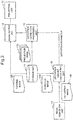
Fig. 7 is a flowchart illustrating an operation of theprojection device 10 according to the present example embodiment. - First of all, the
image output unit 12 acquires thepattern image 120 from thestorage unit 11, and outputs the acquiredpattern image 120. Theprojection unit 13 projects thepattern image 120 output by the image output unit 12 (Step S11). Thepattern image 120 projected from theprojection unit 13 is displayed on a projection surface. - The
camera 20 captures the displayedimage 101 displayed on the projection surface. Theimage acquisition unit 14 acquires the displayedimage 101 captured by the camera, and extracts thedistortion image 140 from the acquired displayed image 101 (Step S12). Theimage acquisition unit 14 outputs the extracteddistortion image 140 to the distortionamount calculating unit 15. - The distortion
amount calculating unit 15 acquires thedistortion image 140 from theimage acquisition unit 14, and also acquires the expectedimage 150 from thestorage unit 11. Then, the distortionamount calculating unit 15 calculates a distortion parameter by comparing thedistortion image 140 with the expected image 150 (Step S13). - Herein, when there remains a triangle to be calibrated among triangles constituting the pattern image, and calibration is continued (Yes in Step S14), the flow returns to Step S11. On the other hand, when the calibration is finished (No in Step S14), the flow proceeds to Step S15.
- When the calibration is finished (No in Step S14), the distortion
correction processing unit 16 acquires a distortion parameter from the distortionamount calculating unit 15. The distortioncorrection processing unit 16 acquires the desiredprojection image 160 from thestorage unit 11, and corrects theprojection image 160 by using the distortion parameter (Step S15). - The
image output unit 12 outputs the correctedprojection image 160 to theprojection unit 13. Theprojection unit 13 projects the corrected projection image 160 (Step S16). - The foregoing is description about an operation of the projection device according to the present example embodiment.
- Herein, calibration to be performed by the projection device according to the present example embodiment is described in further detail with reference to
Fig. 8 to Fig. 10 . -
Fig. 8 is an example in which a displayedimage 104 is displayed on anuneven surface 103. In the example inFig. 8 , the displayedimage 104 is displayed successively by projecting cross-shaped patterns on theuneven surface 103 in the order of a, b, c, d, e, ..., and a distortion parameter is calculated for each triangle to be formed by three vertexes. - When calibration is started, the
projection device 10 projects the patterns a, b, and c successively on theuneven surface 103. The projected cross-shaped patterns form a triangle abc. Thecamera 20 captures theuneven surface 103, and feeds back the triangle abc to theprojection device 10. In this stage, only the triangle abc included in the displayedimage 104 is acquired. - The distortion
amount calculating unit 15 calculates an inverse matrix T-1 by using a relationship expressed by the following Equation (1) with use of the acquired triangle abc and a triangle ABC of an expectedimage 105. The inverse matrix T-1 is an inverse matrix of a transformation matrix T for transforming the triangle abc to the triangle ABC depending on a local state of theuneven surface 103, and corresponds to a distortion parameter. The triangle abc and the triangle ABC in Equation (1) are normally expressed by a two-dimensional coordinate system, but may be expressed by a three-dimensional coordinate system. A size or a component of the transformation matrix T is set in association with a coordinate system or a transformation condition of the triangle abc and the triangle ABC. Note that, when a distortion parameter is calculated, a moving amount of each vertex constituting a triangle, a distortion amount to be obtained from a difference in gradient of each side, a difference in area, and a shape, and the like may be considered.
- Subsequently, the
projection device 10 projects patterns d, e, ..., successively, and obtains an inverse matrix (distortion parameter) in the order of a triangle bcd, a triangle cde, .... Specifically, theprojection device 10 compares triangles included in the displayedimage 104 and the expectedimage 105 and having a correlation, and calculates a distortion parameter for each triangle to be formed by a projection pattern. As a result of the calculation, theprojection device 10 is able to obtain a distortion parameter depending on a local state of theuneven surface 103. - Next, an example in which a projection image is corrected by using an obtained distortion parameter is illustrated. As illustrated in
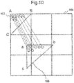
Fig. 10 , the distortioncorrection processing unit 16 corrects aprojection image 106 by using a distortion parameter for each triangle. - Specifically, in order to display a displayed image subjected to distortion correction (hereinafter, distortion corrected image 107) on the
uneven surface 103, the distortioncorrection processing unit 16 calculates a reference pixel position of theprojection image 106 by applying an inverse matrix (distortion parameter) to the distortion correctedimage 107. The distortioncorrection processing unit 16 may calculate a reference pixel position of theprojection image 106 for each pixel of the distortion correctedimage 107. - The distortion
correction processing unit 16 calculates a reference pixel position of theprojection image 106 for each triangle to be defined on the distortion correctedimage 107. In this case, the distortioncorrection processing unit 16 completes an image needed to be displayed on theuneven surface 103 by calculating a reference pixel position of theprojection image 106 with respect to an entire area of the distortion correctedimage 107. Note that the distortioncorrection processing unit 16 may calculate a reference pixel position of theprojection image 106 in a stage when a distortion parameter is calculated for all triangles defined on the distortion correctedimage 107. - As described above, according to the present example embodiment, it is possible to display an image even on a projection surface having complex unevenness, as well as on a flat surface.
- According to the present example embodiment, it is possible to enhance correction accuracy and to enhance image quality by reducing a size of a triangle constituting a pattern image on a projection surface having large unevenness. Further, according to the present example embodiment, it is possible to shorten time required for calibration by increasing a size of a triangle constituting a pattern image on a projection surface having small unevenness.
- Herein, a layout example of the
camera 20 is illustrated (Fig. 11 ). In the example inFig. 11 , thecamera 20 is disposed according to viewpoints of audiences who view an image projected on theuneven surface 100. Specifically, inFig. 11 , thecamera 20 is disposed at a position where audiences view the uneven surface 100 (projection surface). - The
camera 20 captures the displayedimage 101 displayed on theuneven surface 100 from a position where audiences view theuneven surface 100. - The
projection device 10 compares the displayedimage 101 acquired from thecamera 20 with the expectedimage 201, and detects distortion of the displayedimage 101 from a difference between the displayedimage 101 and the expectedimage 201. The distortion reflects distortion which occurs when audiences view theuneven surface 100 from the viewpoints of the audiences. Theprojection device 10 generates a distortion parameter from the distortion, and projects theprojection image 160 corrected by the generated distortion parameter on theuneven surface 100. As a result of the projection, audiences are able to view a projection image without distortion on theuneven surface 100. - In general projection mapping, it is necessary to actually measure dimensions of a wall surface having unevenness where a projection image is displayed. Then, it is necessary to create a drawing with use of a computer aided design (CAD) or the like, taking into consideration a condition of the actually measured uneven surface. Further, it is necessary to create a virtual space within a personal computer by using three-dimensional computer graphics software or the like, and to adjust distortion of an image, while simulating how the image is actually displayed.
- According to the present example embodiment, it is possible to perform calibration easily and within a short time even on site without measuring dimensions of a wall surface and without time and effort for distortion adjustment in a virtual space within a personal computer.
- Next, a projection device according to a second example embodiment of the present invention is described. The projection device according to the second example embodiment performs calibration for projecting a
projection image 160 on anuneven surface 100 having locally large distortion. -
Fig. 12 illustrates an example in which adistortion image 121 displayed on an uneven surface having locally large distortion, and an expectedimage 221 associated with thedistortion image 121 are compared. InFig. 12 , since a projection position of a pattern a is largely distorted, a movingamount 205 between a triangle abc and a triangle ABC is large. - As illustrated in
Fig. 12 , when locally large distortion occurs, a distortionamount calculating unit 15 outputs a command for subdividing a triangle having large distortion among triangles constituting a displayed image of apattern image 120. - A distortion
correction processing unit 16 performs processing of subdividing a triangle having large distortion in response to the command from the distortionamount calculating unit 15. Specifically, the distortioncorrection processing unit 16 subdivides an area constituting an expected image, when distortion equal to or larger than a certain amount occurs. - As illustrated in
Fig. 13 , the distortioncorrection processing unit 16 generates an expectedimage 222 obtained by subdividing a part of the expectedimage 221. Note thatFig. 13 conceptually illustrates that a part of the expectedimage 221 is extracted, and does not accurately illustrate a positional relationship between a triangle ABC and a triangle abc inFig. 12 . In the present example embodiment, it is possible to display an image with further enhanced quality by creating a distortion corrected image from each subdivided area (triangle). - In the example in
Fig. 13 , a triangle ABC is subdivided into four triangles (a triangle AST, a triangle BUT, a triangle CSU, and a triangle SUT). The respective triangles (the triangle AST, the triangle BUT, the triangle CSU, and the triangle SUT) correspond to a triangle ast, a triangle but, a triangle csu, and a triangle sut. - As illustrated in
Fig. 12 , only when comparison is made between the triangle ABC and the triangle abc, it is difficult to display an appropriate image because distortion is too large. In such a case, subdividing the triangle ABC enables to eliminate local distortion, since it is possible to more finely reflect a local state of unevenness. Specifically, according to the present example embodiment, subdividing an area constituting the expectedimage 222 enables to accurately calculate a distortion parameter even when locally large distortion is present. - As described above, according to the present example embodiment, it is possible to provide an image with high quality even for local distortion, by subdividing a pattern image.
- Next, a projection device according to a third example embodiment of the present invention is described. The projection device according to the third example embodiment illustrates an example in which a case that an end portion of a displayed image is lacked in display depending on a state of an uneven surface when projected in an ordinary method is handled. In the present example embodiment, calibration using an end pixel of an image (hereinafter, end pixel calibration) is performed before calibration according to the first example embodiment (main calibration).
- As illustrated in
Fig. 14 , a projection device 10-3 according to the present example embodiment has a configuration in which an endpixel adjusting unit 17 is added to theprojection device 10 according to the first example embodiment. - The end
pixel adjusting unit 17 performs end pixel calibration using an end pixel before the main calibration, when an end portion of a displayed image is lacked. -
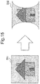
Fig. 15 illustrates an example in which an expected image 231 (left side) desired to be displayed is displayed like a displayed image 232 (right side), depending on a surface state of a projection surface. The displayed image 232 (right side) is displayed on an uneven surface in a state that both side portions are lacked. -
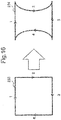
Fig. 16 is a conceptual diagram for describing end pixel calibration. - First of all, in end pixel calibration, end pixel reference is performed along an end portion of the expected
image 231. In end pixel reference, the projection device 10-3 projects pixels of an end portion (hereinafter, end pixels) in the order of 1→2→3→4 as illustrated in the right side ofFig. 16 . - A
camera 20 captures an end pixel projected in the order on the right side ofFig. 16 . The projection device 10-3 calculates an end pixel reference position 234 (right side ofFig. 16 ) which is defined from a position of the end pixel captured by thecamera 20. - Next, as illustrated in the left side of
Fig. 17 , the endpixel adjusting unit 17 generates an image obtained by superimposing the endpixel reference position 234 and the expectedimage 231. In this case, both side portions of the expectedimage 231 are deviated from the endpixel reference position 234. When aprojection image 160 is projected in the aforementioned state, an image is displayed in a state that an end portion of theprojection image 160 is lacked. - Herein, as illustrated in the right side of
Fig. 17 , the endpixel adjusting unit 17 generates a shrunk expectedimage 235 obtained by shrinking the expectedimage 231 in such a manner that the shrunk expectedimage 235 is present within an area of the endpixel reference position 234. - When the main calibration is performed by using the shrunk expected
image 235 generated by the endpixel adjusting unit 17, lacking does not occur even when theprojection image 160 is projected. - As described above, in the projection device according to the present example embodiment, it is possible to appropriately display a projection image in a state that an end portion is not lacked, when the end portion is lacked depending on a condition of a projection surface.
-
Fig. 18 is a block diagram illustrating an example of hardware configurations of the projection devices according to the first to third example embodiments of the present invention. Note thatFig. 18 is a configuration example for implementing the projection devices according to the respective example embodiments, and a configuration may be added/deleted according to a required specification. - A
processor 91 is an arithmetic device for extracting a program stored in astorage medium 98 or the like to amain storage device 95 or the like, and executing the extracted program. Theprocessor 91 may be configured by a general central processing unit (CPU). A part of functions of the distortionamount calculating unit 15 and the distortioncorrection processing unit 16 may be performed by theprocessor 91. - A
projection system 92 is a projection device including a light source, a liquid crystal panel, a projection lens, and the like. The light source is configured by using a halogen lamp, a xenon lamp, a metal halide lamp, an ultra-high pressure mercury lamp, a laser, or the like. The liquid crystal panel partially cuts off or transmits light emitted from the light source. The projection lens is a lens for projecting light transmitted through the liquid crystal panel, on a projection surface. Note that theprojection system 92 may include a control system for controlling a projecting direction, a magnification ratio, and the like. Functions of theprojection unit 13 may be performed by theprojection system 92. - A
converter 93 is a circuit having a function of converting analog data input from outside into digital data, and a function of converting digital data generated inside into analog data. Theconverter 93 may be such that an analog/digital (A/D) converter for converting analog data into digital data, and a digital/analog (D/A) converter for converting digital data into analog data are individually configured. For example, theimage acquisition unit 14 may have an A/D conversion function, and theimage output unit 12 may have a D/A conversion function. - The
main storage device 95 is a device having a storage area for temporarily extracting a program or data handled by theprocessor 91. For example, a random access memory (RAM) may be configured as themain storage device 95. A part of functions of thestorage unit 11 may be performed by themain storage device 95. - An input-
output interface 96 is an interface for transmitting/receiving data to/from input-output devices on outside and inside. For example, the input-output interface 96 is connected to acamera 20. Further, for example, the input-output interface 96 may be connected to an input device such as an unillustrated keyboard and an unillustrated mouse, an unillustrated display, an unillustrated printer, a network, or the like. When theprojection unit 13 is treated as an input-output device, functions of theimage output unit 12 may be performed by the input-output interface 96. - An
image processing circuit 97 is a circuit for performing various processing with respect to image data. Theimage processing circuit 97 is an integrated circuit for performing image processing such as dark current correction, interpolation calculation, color space conversion, gamma correction, aberration correction, noise reduction, and image compression with respect to captured image data, for example. A part of functions of the distortionamount calculating unit 15 and the distortioncorrection processing unit 16 may be performed by theimage processing circuit 97. - The
storage medium 98 is a medium for storing a program and data. For example, it is possible to use a hard disk or the like as thestorage medium 98. Further, a read only memory (ROM) may be added to thestorage medium 98. Functions of thestorage unit 11 may be performed by thestorage medium 98. The storage medium may be implemented by a semiconductor storage medium such as a secure digital (SD) card and a universal serial bus (USB) memory, for example. Further, the storage medium may be implemented by a magnetic storage medium such as a flexible disk, an optical storage medium such as a compact disk (CD) and a digital versatile disc (DVD), or another storage medium. - The foregoing is an example of a hardware configuration for enabling a projection device according to an example embodiment of the present invention. Note that the hardware configuration in
Fig. 18 is an example of a hardware configuration for enabling a projection device according to the present example embodiment, and does not limit the scope of the present invention. Further, a processing program which causes a computer to execute processing by the projection device according to the present example embodiment is also included in the scope of the present invention. Further, a program storage medium recording a processing program according to an example embodiment of the present invention is also included in the scope of the present invention. - In the foregoing, the present invention is described with reference to example embodiments. The present invention, however, is not limited to the aforementioned example embodiments. The configuration and details of the present invention may be modified in various ways comprehensible to a person skilled in the art within the scope of the present invention.
- This application is based upon and claims the benefit of priority from Japanese Patent Application No.
2015-171877, filed on September 1, 2015 -
- 10
- Projection device
- 11
- Storage unit
- 12
- Image output unit
- 13
- Projection unit
- 14
- Image acquisition unit
- 15
- Distortion amount calculating unit
- 16
- Distortion correction processing unit
- 17
- End pixel adjusting unit
- 20
- Camera
- 91
- Processor
- 92
- Projection system
- 93
- Converter
- 95
- Main storage device
- 96
- Input-output interface
- 97
- Image processing circuit
- 98
- Storage medium
Claims (10)
- A projection device comprising:storage means that stores at least a pattern image for detecting distortion depending on a surface state of a projection surface, an expected image associated with a displayed image when the pattern image is displayed on a flat surface, and a desired projection image;projection means that projects, on the projection surface, an image including the pattern image and the desired projection image;image acquisition means that acquires a displayed image of the pattern image displayed on the projection surface, and extracts a distortion image;distortion amount calculating means that calculates a distortion parameter relating to distortion of the projection surface by comparing the expected image with the distortion image;distortion correction processing means that corrects the desired projection image to be projected on the projection surface, by using the distortion parameter; andimage output means that outputs, to the projection means, image data including the desired projection image corrected by the distortion correction processing means, and the pattern image.
- The projection device according to Claim 1, further comprising
a camera that captures the projection surface, and outputs the captured image data to the image acquisition means, wherein
the image acquisition means
extracts a displayed image of the pattern image from the acquired image data, as the distortion image. - The projection device according to Claim 1, wherein
the storage means
stores the pattern image and the expected image divided into a plurality of triangular areas associated with each other, and
the distortion amount calculating means
compares associated areas of the distortion image corresponding to a displayed image of the pattern image, and the expected image, and calculates the distortion parameter. - The projection device according to Claim 3, wherein
the distortion amount calculating means
calculates an inverse matrix of a matrix for transforming a triangle constituting the distortion image to a triangle constituting the expected image, as the distortion parameter. - The projection device according to Claim 3, wherein
the projection means
projects vertexes of a triangle constituting the pattern image successively, and
the distortion amount calculating means
calculates, each time vertexes on a displayed image of the pattern image displayed on the projection surface form a triangle, the distortion parameter relating to a formed triangle successively. - The projection device according to Claim 2, wherein
the camera
is disposed at a position where the projection surface is viewed. - The projection device according to Claim 3, wherein
the distortion amount calculating means
outputs a command for subdividing a triangle in which distortion equal to or larger than a certain amount occurs, among triangles constituting the distortion image, and
the distortion correction processing means
subdivides a triangle constituting the expected image and being associated with a triangle in which distortion equal to or larger than the certain amount occurs, in response to a command of the distortion amount calculating means. - The projection device according to Claim 1, further comprising
end pixel adjusting means that adjusts a display area of an image to be displayed on the projection surface, when a peripheral portion of an image to be displayed on the projection surface is lacked, wherein
the projection means
projects a pixel of an end portion of the expected image on the projection surface,
the image acquisition means
acquires a position of a pixel of the end portion displayed on the projection surface,
the end pixel adjusting means
generates a shrunk expected image obtained by shrinking the expected image in such a manner as to be present within an area of an end pixel reference position to be defined from a position of a pixel of the end portion acquired by the image acquisition means,
the image output means
outputs, to the projection means, the pattern image shrunk in association with the shrunk expected image,
the projection means
projects the shrunk pattern image output by the image output means, on the projection surface, and
the distortion amount calculating means
calculates the distortion parameter by comparing the distortion image corresponding to a displayed image of the shrunk pattern image with the shrunk expected image. - A projection method comprising:projecting a pattern image for detecting distortion depending on a surface state of a projection surface, on the projection surface;acquiring a displayed image of the pattern image displayed on the projection surface, and extracting a distortion image;calculating a distortion parameter of the projection surface by comparing an expected image associated with a displayed image when the pattern image is displayed on a flat surface, with the distortion image;correcting a desired projection image to be projected on the projection surface, by using the distortion parameter; andprojecting the corrected desired projection image on the projection surface.
- A program storage medium storing a projection program that causes a computer to execute:processing of projecting a pattern image for detecting distortion depending on a surface state of a projection surface, on the projection surface;processing of acquiring a displayed image of the pattern image displayed on the projection surface, and extracting a distortion image;processing of calculating a distortion parameter of the projection surface by comparing an expected image associated with a displayed image when the pattern image is displayed on a flat surface, with the distortion image;processing of correcting a desired projection image to be projected on the projection surface, by using the distortion parameter; andprocessing of projecting the corrected desired projection image on the projection surface.
Applications Claiming Priority (2)
| Application Number | Priority Date | Filing Date | Title |
|---|---|---|---|
| JP2015171877 | 2015-09-01 | ||
| PCT/JP2016/003980 WO2017038096A1 (en) | 2015-09-01 | 2016-08-31 | Projection device, projection method and program storage medium |
Publications (3)
| Publication Number | Publication Date |
|---|---|
| EP3346699A1 true EP3346699A1 (en) | 2018-07-11 |
| EP3346699A4 EP3346699A4 (en) | 2019-08-14 |
| EP3346699B1 EP3346699B1 (en) | 2023-02-01 |
Family
ID=58187008
Family Applications (1)
| Application Number | Title | Priority Date | Filing Date |
|---|---|---|---|
| EP16841129.6A Active EP3346699B1 (en) | 2015-09-01 | 2016-08-31 | Projection device, projection method and projection program |
Country Status (5)
| Country | Link |
|---|---|
| US (1) | US10572971B2 (en) |
| EP (1) | EP3346699B1 (en) |
| JP (1) | JP6568223B2 (en) |
| CN (1) | CN108028900B (en) |
| WO (1) | WO2017038096A1 (en) |
Families Citing this family (17)
| Publication number | Priority date | Publication date | Assignee | Title |
|---|---|---|---|---|
| JP6460088B2 (en) * | 2016-12-14 | 2019-01-30 | カシオ計算機株式会社 | Projection apparatus, projection method, and program |
| JP6485655B2 (en) | 2017-03-27 | 2019-03-20 | 日本電気株式会社 | Face authentication device, face authentication method, and face authentication program |
| JP2019008015A (en) * | 2017-06-21 | 2019-01-17 | カシオ計算機株式会社 | Projection apparatus, projection method, and program |
| JP2019047311A (en) * | 2017-09-01 | 2019-03-22 | セイコーエプソン株式会社 | Image projection system and control method thereof |
| JP6642610B2 (en) * | 2018-03-22 | 2020-02-05 | カシオ計算機株式会社 | Projection control device, projection device, projection control method, and program |
| CN110784692B (en) * | 2018-07-31 | 2022-07-05 | 中强光电股份有限公司 | Projection device, projection system and image correction method |
| CN111629190A (en) * | 2019-02-28 | 2020-09-04 | 中强光电股份有限公司 | Projection system and projection method |
| JP7415439B2 (en) * | 2019-10-28 | 2024-01-17 | セイコーエプソン株式会社 | Projector control method and projector |
| JP7621739B2 (en) * | 2020-03-04 | 2025-01-27 | 日本発條株式会社 | A method for inspecting an inspection system, an inspection system, and a computer program. |
| JP7686662B2 (en) | 2020-10-13 | 2025-06-02 | パナソニックホールディングス株式会社 | Installation information acquisition method, correction method, program, and installation information acquisition system |
| CN112532940A (en) * | 2020-11-30 | 2021-03-19 | 广东元一科技实业有限公司 | Pattern deformation method for sheet-shaped workpiece |
| JP7558799B2 (en) * | 2020-12-25 | 2024-10-01 | セイコーエプソン株式会社 | Location determination method, simulation method, location determination system, and simulation system |
| JP7746807B2 (en) * | 2021-10-28 | 2025-10-01 | セイコーエプソン株式会社 | Circuit device and head-up display device |
| US11900845B2 (en) * | 2021-10-28 | 2024-02-13 | Samsung Electronics Co., Ltd. | System and method for optical calibration of a head-mounted display |
| JP2023182032A (en) * | 2022-06-14 | 2023-12-26 | 大成建設株式会社 | Construction drawing projection system, construction drawing projection method |
| JP2024018681A (en) * | 2022-07-29 | 2024-02-08 | セイコーエプソン株式会社 | Pattern image detection method, information processing device, detection system, and program |
| JP2024032228A (en) * | 2022-08-29 | 2024-03-12 | セイコーエプソン株式会社 | Image correction method, information processing device, and program |
Family Cites Families (19)
| Publication number | Priority date | Publication date | Assignee | Title |
|---|---|---|---|---|
| JP4199641B2 (en) | 2003-10-30 | 2008-12-17 | 日本電気株式会社 | Projector device |
| CN100596206C (en) * | 2003-12-10 | 2010-03-24 | 日本电气株式会社 | Projector Color Correction Methods |
| US20040194051A1 (en) * | 2004-05-13 | 2004-09-30 | Croft Bryan L. | Finite element modeling system and method for modeling large-deformations using self-adaptive rezoning indicators derived from eigenvalue testing |
| US20080136976A1 (en) * | 2004-09-01 | 2008-06-12 | Olympus Corporation | Geometric Correction Method in Multi-Projection System |
| KR101225063B1 (en) | 2006-04-04 | 2013-01-24 | 삼성전자주식회사 | Unobtrusive calibration method for projected image compensation and apparatus for the same |
| US9137504B2 (en) * | 2006-06-16 | 2015-09-15 | Hewlett-Packard Development Company, L.P. | System and method for projecting multiple image streams |
| US8376558B2 (en) * | 2008-06-17 | 2013-02-19 | The Invention Science Fund I, Llc | Systems and methods for projecting in response to position change of a projection surface |
| JP5521855B2 (en) * | 2009-09-10 | 2014-06-18 | 株式会社リコー | Projection image area detection device |
| US8355601B2 (en) | 2010-01-15 | 2013-01-15 | Seiko Epson Corporation | Real-time geometry aware projection and fast re-calibration |
| US9398278B2 (en) * | 2011-01-06 | 2016-07-19 | Telenav, Inc. | Graphical display system with adaptive keystone mechanism and method of operation thereof |
| JP5961945B2 (en) | 2011-08-18 | 2016-08-03 | 株式会社リコー | Image processing apparatus, projector and projector system having the image processing apparatus, image processing method, program thereof, and recording medium recording the program |
| US9344695B2 (en) * | 2011-09-15 | 2016-05-17 | Nec Corporation | Automatic projection image correction system, automatic projection image correction method, and non-transitory storage medium |
| US9033516B2 (en) * | 2011-09-27 | 2015-05-19 | Qualcomm Incorporated | Determining motion of projection device |
| JP5465708B2 (en) | 2011-12-05 | 2014-04-09 | 哲也 秋葉 | Projection system and method |
| JP2015080190A (en) | 2013-09-11 | 2015-04-23 | 株式会社リコー | Extraction method, program, extraction apparatus, and image projection apparatus |
| JP5748814B2 (en) | 2013-09-20 | 2015-07-15 | キヤノン株式会社 | Projection type display device and geometric distortion correction method |
| JP2015152686A (en) | 2014-02-12 | 2015-08-24 | 株式会社リコー | image projection device |
| JP6015692B2 (en) | 2014-03-06 | 2016-10-26 | セイコーエプソン株式会社 | Projector, projection state adjustment method, and projection state adjustment program |
| TWI584648B (en) * | 2015-08-24 | 2017-05-21 | 鈺立微電子股份有限公司 | Image capture device with a calibration function and calibration method of an image capture device |
-
2016
- 2016-08-31 US US15/748,689 patent/US10572971B2/en active Active
- 2016-08-31 WO PCT/JP2016/003980 patent/WO2017038096A1/en not_active Ceased
- 2016-08-31 CN CN201680049716.8A patent/CN108028900B/en active Active
- 2016-08-31 JP JP2017537552A patent/JP6568223B2/en active Active
- 2016-08-31 EP EP16841129.6A patent/EP3346699B1/en active Active
Also Published As
| Publication number | Publication date |
|---|---|
| EP3346699A4 (en) | 2019-08-14 |
| CN108028900B (en) | 2020-10-09 |
| US20190005607A1 (en) | 2019-01-03 |
| JP6568223B2 (en) | 2019-08-28 |
| EP3346699B1 (en) | 2023-02-01 |
| CN108028900A (en) | 2018-05-11 |
| US10572971B2 (en) | 2020-02-25 |
| JPWO2017038096A1 (en) | 2018-06-14 |
| WO2017038096A1 (en) | 2017-03-09 |
Similar Documents
| Publication | Publication Date | Title |
|---|---|---|
| EP3346699B1 (en) | Projection device, projection method and projection program | |
| JP6302219B2 (en) | MTF measuring apparatus and MTF measuring program | |
| US9661257B2 (en) | Projection system, image processing device, and projection method | |
| US20130258048A1 (en) | Image signal processor and image signal processing method | |
| JP6344050B2 (en) | Image processing system, image processing apparatus, and program | |
| EP2261852B1 (en) | Image photographic device, image photographic method, and image photographic program | |
| JP7145432B2 (en) | Projection system, image processing device and projection method | |
| EP3594618B1 (en) | Three-dimensional shape measurement device, three-dimensional shape measurement method, and program | |
| US11962946B2 (en) | Image processing apparatus, display system, image processing method, and medium | |
| EP3438602B1 (en) | Dimension measurement apparatus and control method of the same | |
| JP6594170B2 (en) | Image processing apparatus, image processing method, image projection system, and program | |
| JP2002071315A (en) | Projection planar measuring system | |
| JP2017129942A (en) | Information processing apparatus, information processing method, and program | |
| EP3606061B1 (en) | Projection device, projection system and an image calibration method | |
| JP2016072691A (en) | Image processing apparatus, control method therefor, and program | |
| JP7329951B2 (en) | Image processing device and its control method | |
| US9582887B2 (en) | Methods and apparatus for determining field of view dependent depth map correction values | |
| JP5955003B2 (en) | Image processing apparatus, image processing method, and program | |
| US10360719B2 (en) | Method and apparatus for obtaining high-quality textures | |
| US9449251B2 (en) | Image processing apparatus, image processing method, and medium | |
| US20160295187A1 (en) | Information processing device and projection apparatus | |
| EP3605447B1 (en) | Image correction device, image correction method and program | |
| HK1248044A1 (en) | Projection device, projection method and program storage medium | |
| US10097772B2 (en) | Image processing device and image processing method | |
| US20250247509A1 (en) | Correction method, system, and non-transitory computer-readable storage medium storing program |
Legal Events
| Date | Code | Title | Description |
|---|---|---|---|
| STAA | Information on the status of an ep patent application or granted ep patent |
Free format text: STATUS: THE INTERNATIONAL PUBLICATION HAS BEEN MADE |
|
| PUAI | Public reference made under article 153(3) epc to a published international application that has entered the european phase |
Free format text: ORIGINAL CODE: 0009012 |
|
| STAA | Information on the status of an ep patent application or granted ep patent |
Free format text: STATUS: REQUEST FOR EXAMINATION WAS MADE |
|
| 17P | Request for examination filed |
Effective date: 20180329 |
|
| AK | Designated contracting states |
Kind code of ref document: A1 Designated state(s): AL AT BE BG CH CY CZ DE DK EE ES FI FR GB GR HR HU IE IS IT LI LT LU LV MC MK MT NL NO PL PT RO RS SE SI SK SM TR |
|
| AX | Request for extension of the european patent |
Extension state: BA ME |
|
| DAV | Request for validation of the european patent (deleted) | ||
| DAX | Request for extension of the european patent (deleted) | ||
| RIC1 | Information provided on ipc code assigned before grant |
Ipc: G03B 21/14 20060101ALI20190403BHEP Ipc: G03B 21/00 20060101ALI20190403BHEP Ipc: H04N 9/31 20060101AFI20190403BHEP |
|
| REG | Reference to a national code |
Ref country code: DE Ref legal event code: R079 Ref document number: 602016077725 Country of ref document: DE Free format text: PREVIOUS MAIN CLASS: H04N0005740000 Ipc: H04N0009310000 |
|
| A4 | Supplementary search report drawn up and despatched |
Effective date: 20190717 |
|
| RIC1 | Information provided on ipc code assigned before grant |
Ipc: G03B 21/00 20060101ALI20190711BHEP Ipc: G03B 21/14 20060101ALI20190711BHEP Ipc: H04N 9/31 20060101AFI20190711BHEP |
|
| STAA | Information on the status of an ep patent application or granted ep patent |
Free format text: STATUS: EXAMINATION IS IN PROGRESS |
|
| 17Q | First examination report despatched |
Effective date: 20210125 |
|
| GRAP | Despatch of communication of intention to grant a patent |
Free format text: ORIGINAL CODE: EPIDOSNIGR1 |
|
| STAA | Information on the status of an ep patent application or granted ep patent |
Free format text: STATUS: GRANT OF PATENT IS INTENDED |
|
| INTG | Intention to grant announced |
Effective date: 20220913 |
|
| GRAS | Grant fee paid |
Free format text: ORIGINAL CODE: EPIDOSNIGR3 |
|
| GRAA | (expected) grant |
Free format text: ORIGINAL CODE: 0009210 |
|
| STAA | Information on the status of an ep patent application or granted ep patent |
Free format text: STATUS: THE PATENT HAS BEEN GRANTED |
|
| AK | Designated contracting states |
Kind code of ref document: B1 Designated state(s): AL AT BE BG CH CY CZ DE DK EE ES FI FR GB GR HR HU IE IS IT LI LT LU LV MC MK MT NL NO PL PT RO RS SE SI SK SM TR |
|
| REG | Reference to a national code |
Ref country code: GB Ref legal event code: FG4D |
|
| REG | Reference to a national code |
Ref country code: CH Ref legal event code: EP Ref country code: AT Ref legal event code: REF Ref document number: 1547220 Country of ref document: AT Kind code of ref document: T Effective date: 20230215 |
|
| REG | Reference to a national code |
Ref country code: DE Ref legal event code: R096 Ref document number: 602016077725 Country of ref document: DE |
|
| REG | Reference to a national code |
Ref country code: IE Ref legal event code: FG4D |
|
| REG | Reference to a national code |
Ref country code: LT Ref legal event code: MG9D |
|
| REG | Reference to a national code |
Ref country code: NL Ref legal event code: MP Effective date: 20230201 |
|
| REG | Reference to a national code |
Ref country code: AT Ref legal event code: MK05 Ref document number: 1547220 Country of ref document: AT Kind code of ref document: T Effective date: 20230201 |
|
| PG25 | Lapsed in a contracting state [announced via postgrant information from national office to epo] |
Ref country code: RS Free format text: LAPSE BECAUSE OF FAILURE TO SUBMIT A TRANSLATION OF THE DESCRIPTION OR TO PAY THE FEE WITHIN THE PRESCRIBED TIME-LIMIT Effective date: 20230201 Ref country code: PT Free format text: LAPSE BECAUSE OF FAILURE TO SUBMIT A TRANSLATION OF THE DESCRIPTION OR TO PAY THE FEE WITHIN THE PRESCRIBED TIME-LIMIT Effective date: 20230601 Ref country code: NO Free format text: LAPSE BECAUSE OF FAILURE TO SUBMIT A TRANSLATION OF THE DESCRIPTION OR TO PAY THE FEE WITHIN THE PRESCRIBED TIME-LIMIT Effective date: 20230501 Ref country code: NL Free format text: LAPSE BECAUSE OF FAILURE TO SUBMIT A TRANSLATION OF THE DESCRIPTION OR TO PAY THE FEE WITHIN THE PRESCRIBED TIME-LIMIT Effective date: 20230201 Ref country code: LV Free format text: LAPSE BECAUSE OF FAILURE TO SUBMIT A TRANSLATION OF THE DESCRIPTION OR TO PAY THE FEE WITHIN THE PRESCRIBED TIME-LIMIT Effective date: 20230201 Ref country code: LT Free format text: LAPSE BECAUSE OF FAILURE TO SUBMIT A TRANSLATION OF THE DESCRIPTION OR TO PAY THE FEE WITHIN THE PRESCRIBED TIME-LIMIT Effective date: 20230201 Ref country code: HR Free format text: LAPSE BECAUSE OF FAILURE TO SUBMIT A TRANSLATION OF THE DESCRIPTION OR TO PAY THE FEE WITHIN THE PRESCRIBED TIME-LIMIT Effective date: 20230201 Ref country code: ES Free format text: LAPSE BECAUSE OF FAILURE TO SUBMIT A TRANSLATION OF THE DESCRIPTION OR TO PAY THE FEE WITHIN THE PRESCRIBED TIME-LIMIT Effective date: 20230201 Ref country code: AT Free format text: LAPSE BECAUSE OF FAILURE TO SUBMIT A TRANSLATION OF THE DESCRIPTION OR TO PAY THE FEE WITHIN THE PRESCRIBED TIME-LIMIT Effective date: 20230201 |
|
| PG25 | Lapsed in a contracting state [announced via postgrant information from national office to epo] |
Ref country code: SE Free format text: LAPSE BECAUSE OF FAILURE TO SUBMIT A TRANSLATION OF THE DESCRIPTION OR TO PAY THE FEE WITHIN THE PRESCRIBED TIME-LIMIT Effective date: 20230201 Ref country code: PL Free format text: LAPSE BECAUSE OF FAILURE TO SUBMIT A TRANSLATION OF THE DESCRIPTION OR TO PAY THE FEE WITHIN THE PRESCRIBED TIME-LIMIT Effective date: 20230201 Ref country code: IS Free format text: LAPSE BECAUSE OF FAILURE TO SUBMIT A TRANSLATION OF THE DESCRIPTION OR TO PAY THE FEE WITHIN THE PRESCRIBED TIME-LIMIT Effective date: 20230601 Ref country code: GR Free format text: LAPSE BECAUSE OF FAILURE TO SUBMIT A TRANSLATION OF THE DESCRIPTION OR TO PAY THE FEE WITHIN THE PRESCRIBED TIME-LIMIT Effective date: 20230502 Ref country code: FI Free format text: LAPSE BECAUSE OF FAILURE TO SUBMIT A TRANSLATION OF THE DESCRIPTION OR TO PAY THE FEE WITHIN THE PRESCRIBED TIME-LIMIT Effective date: 20230201 |
|
| PG25 | Lapsed in a contracting state [announced via postgrant information from national office to epo] |
Ref country code: SM Free format text: LAPSE BECAUSE OF FAILURE TO SUBMIT A TRANSLATION OF THE DESCRIPTION OR TO PAY THE FEE WITHIN THE PRESCRIBED TIME-LIMIT Effective date: 20230201 Ref country code: RO Free format text: LAPSE BECAUSE OF FAILURE TO SUBMIT A TRANSLATION OF THE DESCRIPTION OR TO PAY THE FEE WITHIN THE PRESCRIBED TIME-LIMIT Effective date: 20230201 Ref country code: EE Free format text: LAPSE BECAUSE OF FAILURE TO SUBMIT A TRANSLATION OF THE DESCRIPTION OR TO PAY THE FEE WITHIN THE PRESCRIBED TIME-LIMIT Effective date: 20230201 Ref country code: DK Free format text: LAPSE BECAUSE OF FAILURE TO SUBMIT A TRANSLATION OF THE DESCRIPTION OR TO PAY THE FEE WITHIN THE PRESCRIBED TIME-LIMIT Effective date: 20230201 Ref country code: CZ Free format text: LAPSE BECAUSE OF FAILURE TO SUBMIT A TRANSLATION OF THE DESCRIPTION OR TO PAY THE FEE WITHIN THE PRESCRIBED TIME-LIMIT Effective date: 20230201 |
|
| REG | Reference to a national code |
Ref country code: DE Ref legal event code: R097 Ref document number: 602016077725 Country of ref document: DE |
|
| PG25 | Lapsed in a contracting state [announced via postgrant information from national office to epo] |
Ref country code: SK Free format text: LAPSE BECAUSE OF FAILURE TO SUBMIT A TRANSLATION OF THE DESCRIPTION OR TO PAY THE FEE WITHIN THE PRESCRIBED TIME-LIMIT Effective date: 20230201 |
|
| PLBE | No opposition filed within time limit |
Free format text: ORIGINAL CODE: 0009261 |
|
| STAA | Information on the status of an ep patent application or granted ep patent |
Free format text: STATUS: NO OPPOSITION FILED WITHIN TIME LIMIT |
|
| 26N | No opposition filed |
Effective date: 20231103 |
|
| PG25 | Lapsed in a contracting state [announced via postgrant information from national office to epo] |
Ref country code: SI Free format text: LAPSE BECAUSE OF FAILURE TO SUBMIT A TRANSLATION OF THE DESCRIPTION OR TO PAY THE FEE WITHIN THE PRESCRIBED TIME-LIMIT Effective date: 20230201 |
|
| PG25 | Lapsed in a contracting state [announced via postgrant information from national office to epo] |
Ref country code: MC Free format text: LAPSE BECAUSE OF FAILURE TO SUBMIT A TRANSLATION OF THE DESCRIPTION OR TO PAY THE FEE WITHIN THE PRESCRIBED TIME-LIMIT Effective date: 20230201 |
|
| REG | Reference to a national code |
Ref country code: CH Ref legal event code: PL |
|
| PG25 | Lapsed in a contracting state [announced via postgrant information from national office to epo] |
Ref country code: MC Free format text: LAPSE BECAUSE OF FAILURE TO SUBMIT A TRANSLATION OF THE DESCRIPTION OR TO PAY THE FEE WITHIN THE PRESCRIBED TIME-LIMIT Effective date: 20230201 |
|
| PG25 | Lapsed in a contracting state [announced via postgrant information from national office to epo] |
Ref country code: LU Free format text: LAPSE BECAUSE OF NON-PAYMENT OF DUE FEES Effective date: 20230831 |
|
| PG25 | Lapsed in a contracting state [announced via postgrant information from national office to epo] |
Ref country code: LU Free format text: LAPSE BECAUSE OF NON-PAYMENT OF DUE FEES Effective date: 20230831 Ref country code: CH Free format text: LAPSE BECAUSE OF NON-PAYMENT OF DUE FEES Effective date: 20230831 |
|
| REG | Reference to a national code |
Ref country code: BE Ref legal event code: MM Effective date: 20230831 |
|
| REG | Reference to a national code |
Ref country code: IE Ref legal event code: MM4A |
|
| PG25 | Lapsed in a contracting state [announced via postgrant information from national office to epo] |
Ref country code: IE Free format text: LAPSE BECAUSE OF NON-PAYMENT OF DUE FEES Effective date: 20230831 |
|
| PG25 | Lapsed in a contracting state [announced via postgrant information from national office to epo] |
Ref country code: IE Free format text: LAPSE BECAUSE OF NON-PAYMENT OF DUE FEES Effective date: 20230831 |
|
| PG25 | Lapsed in a contracting state [announced via postgrant information from national office to epo] |
Ref country code: BE Free format text: LAPSE BECAUSE OF NON-PAYMENT OF DUE FEES Effective date: 20230831 |
|
| PG25 | Lapsed in a contracting state [announced via postgrant information from national office to epo] |
Ref country code: BG Free format text: LAPSE BECAUSE OF FAILURE TO SUBMIT A TRANSLATION OF THE DESCRIPTION OR TO PAY THE FEE WITHIN THE PRESCRIBED TIME-LIMIT Effective date: 20230201 |
|
| PG25 | Lapsed in a contracting state [announced via postgrant information from national office to epo] |
Ref country code: BG Free format text: LAPSE BECAUSE OF FAILURE TO SUBMIT A TRANSLATION OF THE DESCRIPTION OR TO PAY THE FEE WITHIN THE PRESCRIBED TIME-LIMIT Effective date: 20230201 |
|
| PG25 | Lapsed in a contracting state [announced via postgrant information from national office to epo] |
Ref country code: CY Free format text: LAPSE BECAUSE OF FAILURE TO SUBMIT A TRANSLATION OF THE DESCRIPTION OR TO PAY THE FEE WITHIN THE PRESCRIBED TIME-LIMIT; INVALID AB INITIO Effective date: 20160831 |
|
| PG25 | Lapsed in a contracting state [announced via postgrant information from national office to epo] |
Ref country code: HU Free format text: LAPSE BECAUSE OF FAILURE TO SUBMIT A TRANSLATION OF THE DESCRIPTION OR TO PAY THE FEE WITHIN THE PRESCRIBED TIME-LIMIT; INVALID AB INITIO Effective date: 20160831 |
|
| PGFP | Annual fee paid to national office [announced via postgrant information from national office to epo] |
Ref country code: DE Payment date: 20250820 Year of fee payment: 10 |
|
| PGFP | Annual fee paid to national office [announced via postgrant information from national office to epo] |
Ref country code: IT Payment date: 20250825 Year of fee payment: 10 |
|
| PGFP | Annual fee paid to national office [announced via postgrant information from national office to epo] |
Ref country code: GB Payment date: 20250821 Year of fee payment: 10 |
|
| PGFP | Annual fee paid to national office [announced via postgrant information from national office to epo] |
Ref country code: FR Payment date: 20250828 Year of fee payment: 10 |
|
| PG25 | Lapsed in a contracting state [announced via postgrant information from national office to epo] |
Ref country code: TR Free format text: LAPSE BECAUSE OF FAILURE TO SUBMIT A TRANSLATION OF THE DESCRIPTION OR TO PAY THE FEE WITHIN THE PRESCRIBED TIME-LIMIT Effective date: 20230201 |