EP3346608A1 - Rf amplifier - Google Patents
Rf amplifier Download PDFInfo
- Publication number
- EP3346608A1 EP3346608A1 EP17150707.2A EP17150707A EP3346608A1 EP 3346608 A1 EP3346608 A1 EP 3346608A1 EP 17150707 A EP17150707 A EP 17150707A EP 3346608 A1 EP3346608 A1 EP 3346608A1
- Authority
- EP
- European Patent Office
- Prior art keywords
- amplifier
- base
- common
- branch
- emitter
- Prior art date
- Legal status (The legal status is an assumption and is not a legal conclusion. Google has not performed a legal analysis and makes no representation as to the accuracy of the status listed.)
- Granted
Links
Images




Classifications
-
- H—ELECTRICITY
- H03—ELECTRONIC CIRCUITRY
- H03F—AMPLIFIERS
- H03F1/00—Details of amplifiers with only discharge tubes, only semiconductor devices or only unspecified devices as amplifying elements
- H03F1/32—Modifications of amplifiers to reduce non-linear distortion
-
- H—ELECTRICITY
- H03—ELECTRONIC CIRCUITRY
- H03F—AMPLIFIERS
- H03F1/00—Details of amplifiers with only discharge tubes, only semiconductor devices or only unspecified devices as amplifying elements
- H03F1/32—Modifications of amplifiers to reduce non-linear distortion
- H03F1/3205—Modifications of amplifiers to reduce non-linear distortion in field-effect transistor amplifiers
-
- H—ELECTRICITY
- H03—ELECTRONIC CIRCUITRY
- H03F—AMPLIFIERS
- H03F3/00—Amplifiers with only discharge tubes or only semiconductor devices as amplifying elements
- H03F3/189—High-frequency amplifiers, e.g. radio frequency amplifiers
- H03F3/19—High-frequency amplifiers, e.g. radio frequency amplifiers with semiconductor devices only
- H03F3/195—High-frequency amplifiers, e.g. radio frequency amplifiers with semiconductor devices only in integrated circuits
-
- H—ELECTRICITY
- H03—ELECTRONIC CIRCUITRY
- H03F—AMPLIFIERS
- H03F3/00—Amplifiers with only discharge tubes or only semiconductor devices as amplifying elements
- H03F3/20—Power amplifiers, e.g. Class B amplifiers, Class C amplifiers
- H03F3/21—Power amplifiers, e.g. Class B amplifiers, Class C amplifiers with semiconductor devices only
- H03F3/213—Power amplifiers, e.g. Class B amplifiers, Class C amplifiers with semiconductor devices only in integrated circuits
-
- H—ELECTRICITY
- H03—ELECTRONIC CIRCUITRY
- H03F—AMPLIFIERS
- H03F2200/00—Indexing scheme relating to amplifiers
- H03F2200/225—Indexing scheme relating to amplifiers the input circuit of an amplifying stage comprising an LC-network
-
- H—ELECTRICITY
- H03—ELECTRONIC CIRCUITRY
- H03F—AMPLIFIERS
- H03F2200/00—Indexing scheme relating to amplifiers
- H03F2200/366—Multiple MOSFETs are coupled in parallel
-
- H—ELECTRICITY
- H03—ELECTRONIC CIRCUITRY
- H03F—AMPLIFIERS
- H03F2200/00—Indexing scheme relating to amplifiers
- H03F2200/391—Indexing scheme relating to amplifiers the output circuit of an amplifying stage comprising an LC-network
-
- H—ELECTRICITY
- H03—ELECTRONIC CIRCUITRY
- H03F—AMPLIFIERS
- H03F2200/00—Indexing scheme relating to amplifiers
- H03F2200/402—A series resonance being added in shunt in the output circuit, e.g. base, gate, of an amplifier stage
-
- H—ELECTRICITY
- H03—ELECTRONIC CIRCUITRY
- H03F—AMPLIFIERS
- H03F2200/00—Indexing scheme relating to amplifiers
- H03F2200/42—Indexing scheme relating to amplifiers the input to the amplifier being made by capacitive coupling means
-
- H—ELECTRICITY
- H03—ELECTRONIC CIRCUITRY
- H03F—AMPLIFIERS
- H03F2200/00—Indexing scheme relating to amplifiers
- H03F2200/451—Indexing scheme relating to amplifiers the amplifier being a radio frequency amplifier
-
- H—ELECTRICITY
- H03—ELECTRONIC CIRCUITRY
- H03F—AMPLIFIERS
- H03F2200/00—Indexing scheme relating to amplifiers
- H03F2200/498—A resistor being added in the source circuit of a transistor amplifier stage as degenerating element
-
- H—ELECTRICITY
- H03—ELECTRONIC CIRCUITRY
- H03F—AMPLIFIERS
- H03F2200/00—Indexing scheme relating to amplifiers
- H03F2200/75—Indexing scheme relating to amplifiers the amplifier stage being a common source configuration MOSFET
Definitions
- This disclosure relates to Radio-Frequency (RF) Amplifiers implemented with bipolar transistors.
- RF amplifiers typically have components with non-linear behaviour which may result in distortion of an incoming signal due to unwanted harmonics resulting from the mixing of different frequencies.
- third-order intermodulation distortion (IM3) in bipolar amplifiers is harmful as it causes interference with the adjacent transmission channels. This distortion may be significant due to the exponential voltage-to-current transfer of bipolar devices.
- the IM3 distortion in general is caused by direct mixing of the input components through the third-order power-series coefficient, denoted K3, of the exponential nonlinearity, and indirect mixing of the input components with the second-order components at baseband (IM2) and 2 nd harmonic (HD2) frequencies.
- an RF amplifier comprising an input, an output, a parallel arrangement of a first branch and at least one further branch, each branch comprising a bipolar transistor in a degenerative emitter configuration having a base coupled to the input, a collector coupled to a common collector node, and an emitter degeneration impedance arranged between the emitter and a common rail; wherein the common collector node is coupled to the output, the base of the first branch bipolar transistor is biased at a first bias voltage and the base of the at least one further branch bipolar transistor is biased at a bias voltage offset from the first bias voltage and wherein in operation a IM3 distortion current output by the first branch bipolar transistor is in antiphase to a IM3 distortion current output by the at least one further branch bipolar transistor.
- the RF amplifier may further comprise a resonant circuit coupled between the input and the common rail.
- the resonant circuit comprises a series arrangement of an inductance and a capacitance.
- the inductance and capacitance may have a variable value.
- the common rail may be a ground.
- the value of the respective emitter degeneration impedance in each branch is within 10 percent of the ratio of the transit time and the base emitter junction capacitance of the respective bipolar transistor, and wherein the phase of the IM3 distortion current is independent of the bias voltage.
- each branch may comprise a capacitance arranged between the base of the bipolar transistor and the emitter of the bipolar transistor and wherein the phase of the IM3 distortion current is independent of the bias voltage.
- the emitter degeneration impedance in each branch may comprise a resistance in parallel with a capacitance and wherein the phase of the IM3 distortion current is independent of the bias voltage.
- each of the first branch and the at least one further branch may further comprise an AC coupling capacitor arranged between the input and the respective base of the first branch and at least one further branch bipolar transistors.
- Embodiments of the RF amplifier may further comprise an output stage comprising a RF choke arranged between a supply rail and the common collector node, and a capacitance arranged between the common collector node and the output.
- the bipolar transistors may be NPN transistors.
- each branch may comprise a respective bias circuit coupled to the base of the respective bipolar transistor and wherein the bias circuit comprises a gyrator.
- the gyrator may comprise a NPN bipolar transistor, a first resistance arranged between a supply voltage rail and the collector, a second resistance arranged between the collector and the base and a capacitance arranged between the base and a ground rail.
- Embodiments of the RF amplifier may further comprise a common-base stage comprising a bipolar transistor having an emitter coupled to the common collector node, a collector coupled to the amplifier output, and a base connected to a common-base bias circuit.
- the RF amplifier may comprise a first common-base stage comprising a first common-base stage bipolar transistor having an emitter coupled to the first branch, a collector coupled to the common collector node, and a base connected to a common-base bias circuit, and at least one further common-base stage comprising at least one further common-base stage bipolar transistor having an emitter coupled to the at least one further branch, a collector coupled to the common collector node, and a base connected to the common-base bias circuit.
- Embodiments of the RF amplifier may be configured as a class A or class AB amplifier.
- Embodiments of the RF amplifier may be included in wireless local area network (WLAN) receivers.
- WLAN wireless local area network
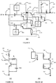
- Figure 1 shows a RF amplifier 100 which includes an input 106, an output 110, and a first amplifier branch 102a arranged in parallel with a second amplifier branch 102b.
- the first amplifier branch 102a and second amplifier branch 102b may also be referred to as a common-emitter (CE) stage.
- CE common-emitter
- the first amplifier branch 102a includes a first bipolar NPN transistor T1 a arranged in a degenerative emitter configuration together with a first emitter degeneration impedance Z e a.
- the base of the bipolar NPN transistor T1a may be connected to the input 106.
- the emitter of the first bipolar NPN transistor T1a may be connected to a first terminal of the emitter degeneration impedance Z e a.
- a second terminal of the emitter degeneration impedance Z e a may be connected to a common rail 112 which may be a ground.
- the collector of the bipolar NPN transistor T1a may be connected to a common collector node 108.
- the second amplifier branch 102b includes a second bipolar NPN transistor T1b arranged in a degenerative emitter configuration together with a second emitter degeneration impedance Z e b.
- the base of the second bipolar NPN transistor T1b may be connected to the input 106.
- the emitter of the second bipolar NPN transistor T1b may be connected to a first terminal of the emitter degeneration impedance Z e b.
- a second terminal of the emitter degeneration impedance Z e b may be connected to a common rail 112 which may be a ground.
- the collector of the bipolar NPN transistor T1b may be connected to the common collector node 108.
- the common collector node 108 may be connected to the amplifier output 110.
- a bias circuit 104 may be connected to the base of the first bipolar transistor T1a and the second bipolar transistor T1b.
- the RF amplifier 100 may receive a signal on the input from a signal source 114.
- the total output current is the sum of the collector currents from the first bipolar transistor T1a and the second bipolar transistor T1b.
- the bias circuit 104 may bias the bases of the first NPN transistor T1a and the second NPN transistor T1b such that there is a voltage offset between them.
- the first NPN transistor T1a and the second NPN transistor T1b are degenerated and biased in such a way that their individual K3 coefficients are equal in magnitude but have opposite sign. In this way, the overall K3 coefficient can be set equal to zero. Note however, that the bases of T1a and T1b need to be terminated in a low impedance at the second-harmonic (H2) and at baseband (IM2) frequencies in order to avoid unwanted IM3 terms from additional indirect mixing at the base-emitter junction.
- H2 second-harmonic
- IM2 baseband
- the nonlinear IM3 currents in the two degenerated CE stages need to have an equal magnitude and opposite phase to achieve an overall IM3 cancellation.
- the maximum (positive sign) and minimum (negative sign) of the third-order Taylor coefficient as a function of base-emitter voltage has to be found.
- V be -I c relationship approximates a quadratic function for a part of the bias range.
- the transistor displays an approximately ohmic behaviour.
- the diffusion capacitance, resulting from the forward base-emitter transit time ⁇ f , and the base-emitter depletion capacitance may also affect the nonlinear third-order intermodulation.
- Figure 2 shows a small signal model 150 of one of a single branch common-emitter stage 102a.
- ⁇ be is the base-emitter voltage and K 2gm is the second-order Taylor coefficient of the exponential collector current to base-emitter voltage relationship.
- ⁇ is the current gain
- ⁇ f is the forward base-emitter transit time
- B S z b / ⁇ + Z e + s ⁇ f Z b + Z e 1 + g m z b / ⁇ + Z e + sC ⁇ Z b + Z e
- B(s) represents the transfer function from the second-order non-linear currents, generated by the exponential distortion, to the second-order base-emitter voltage.
- This function B(s) may introduce different phase shifts to the second-order voltages, mainly the 2 nd harmonic voltages, depending on the values of Z b , Z e , and g m .
- Z e ⁇ f / C je
- the IM3 collector currents of the two branches may have different phases, due to the shift introduced by reactive components, such as the base-emitter diffusion and depletion capacitances. Signals that are generated by indirect mixing inside each transistor T1a, T1b, may experience different phase shifts, due to the different operating points of the two transistors.
- FIG. 3 shows a RF amplifier 200 according to an embodiment.
- a first amplifier branch or CE-stage 202a includes a first bipolar NPN transistor T1a' arranged in a degenerative emitter configuration together with a first emitter degeneration impedance Z e a', and an AC coupling capacitor C1a.
- An input 206 may be connected to a first terminal of an AC coupling capacitor C1a.
- the base of the bipolar NPN transistor T1a' may be connected to a second terminal of the AC coupling capacitor C1a.
- the base of the bipolar NPN transistor T1a' may be connected to a first bias supply rail 204a.
- the emitter of the first bipolar NPN transistor T1a' may be connected to a first terminal of the emitter degeneration impedance Z e a'.
- a second terminal of the emitter degeneration impedance Z e a' may be connected to a common rail 212 which may be a ground.
- the collector of the bipolar NPN transistor T1a' may be connected to a common collector node 208.
- a second amplifier branch 202b includes a second bipolar NPN transistor T1b' arranged in a degenerative emitter configuration together with a second emitter degeneration impedance Z e b', and an AC coupling capacitor C1b.
- An input 206 may be connected to a first terminal of an AC coupling capacitor C1b.
- the base of the bipolar NPN transistor T1b' may be connected to a second terminal of the AC coupling capacitor C1b.
- the base of the bipolar NPN transistor T1b' may be connected to a second bias supply rail 204b.
- the emitter of the second bipolar NPN transistor T1b' may be connected to a first terminal of the emitter degeneration impedance Z e b'.
- a second terminal of the emitter degeneration impedance Z e b' may be connected to a common rail 212 which may be a ground.
- the collector of the bipolar NPN transistor T1b' may be connected to a common collector node 208.
- An amplifier output stage 220 may include an output AC coupling capacitor C3 and a choke inductance L3.
- the common collector node 208 may be connected to a first terminal of the output AC coupling capacitor C3.
- a second terminal of the output AC coupling capacitor C3 may be connected to the amplifier output 210.
- the choke inductance L3 may be connected between the common collector node 308 and a supply rail 214.
- a resonant circuit 216 may include a series arrangement of an inductor L1 and a capacitor C2 connected between the amplifier input 206 and the common rail 212.
- the inductor L1 and the capacitor C2 may be variable or fixed. In other examples, different components may be used to form a resonant circuit.
- the amplifier input 206 may receive an input signal from a signal source 216 represented by a voltage source Vs in series with a resistance Rs.
- the amplifier output 210 may be connected to a load represented as a load resistance RL.
- the total output current provided is the sum of the collector currents from the first bipolar transistor T1a and the second bipolar transistor T1b.
- the bases of transistors T1a' and T1b' are biased at different voltages applied to the first bias supply rail 204a and 204b by respective bias circuits (not shown).
- the transistors T1a and T1b may be dimensioned and the values of Z e a' and Z e b' to satisfy the relation of equations (2)-(4), and (9) similarly to the RF amplifier 100.
- the two IM3 currents are exactly in anti-phase, resulting in effective cancellation of the K3 coefficient. Since the IM3 currents are in antiphase, the RF amplifier may have improved linearity as the direct mixing contribution to the IM3 current may be cancelled. At the same time, any unwanted IM3 terms generated by indirect mixing may be removed by zeroing the input voltage in the out-of-band frequencies. For the Baseband frequencies, this may be achieved by using biasing circuits that present a low output impedance Z out to the base node where Z out ⁇ Z in ⁇ Z source 10 , Z in is the input impedance and Z source is the source impedance.
- second harmonic frequencies may contribute significantly to the unwanted IM3 currents that result from indirect mixing.
- the 2 nd harmonic frequencies at the input 206 may be shorted to the common rail 212.
- the linearity of the bipolar amplifier 200 may be significantly improved.
- Figure 4a shows a graph 250 of the results of simulation of the RF amplifier circuit 200 when a two-tone input frequency is applied.
- the x-axis 252 shows the quiescent collector bias current on a logarithmic scale in amps up to 50 mA resulting from a sweep of the input biasing voltage.
- the y-axis 254 is a linear scale showing the value of the third-order output power intercept point (OIP3) in dBm ranging from 0 to 70.
- the line 256 shows the variation in OIP3 for the higher IM3 harmonic (OIP3H).
- Line 258 shows the variation in OIP3 for the lower IM3 harmonic (OIP3L). As can be seen the OIP3 variation with biasing current is virtually identical in each case.
- the x-axis 262 shows the quiescent collector bias current on a logarithmic scale in amps up to 50 mA resulting from a sweep of the input biasing voltage.
- the y-axis 264 shows the value of the third-order output power intercept point (OIP3) in dBm ranging from 0 to 70.
- OIP3 third-order output power intercept point
- the line 266 shows the variation in OIP3 for the higher IM3 harmonic (OIP3H).
- Line 268 shows the variation in OIP3 for the lower IM3 harmonic (OIP3L).
- a first common-emitter branch 302a may include a first bias circuit 304a, a first bipolar NPN transistor T1a" arranged in a degenerative emitter configuration together with a first emitter degeneration impedance Z e a", and an AC coupling capacitor C1a'.
- An amplifier input 306 may be connected to a first terminal of an AC coupling capacitor C1a'.
- the base of the bipolar NPN transistor T1a" may be connected to a second terminal of the AC coupling capacitor C1a'.
- the base of the bipolar NPN transistor T1a" may be connected to the first bias circuit 304a.
- the emitter of the first bipolar NPN transistor T1a" may be connected to a first terminal of the emitter degeneration impedance Z e a".
- a second terminal of the emitter degeneration impedance Z e a" may be connected to a common rail 312 which may be a ground.
- the collector of the bipolar NPN transistor T1a" may be connected to a common collector node 308.
- a second common-emitter branch 302b may include a second bipolar NPN transistor T1b" arranged in a degenerative emitter configuration together with a second emitter degeneration impedance Z e b", and an AC coupling capacitor C1b'.
- the amplifier input 306 may be connected to a first terminal of an AC coupling capacitor C1b'.
- the base of the bipolar NPN transistor T1b" may be connected to a second terminal of the AC coupling capacitor C1b.
- the base of the bipolar NPN transistor T1b' may be connected to the second bias circuit 304b.
- the emitter of the second bipolar NPN transistor T1b" may be connected to a first terminal of the emitter degeneration impedance Z e b".
- a second terminal of the emitter degeneration impedance Z e b" may be connected to a common rail 312 which may be a ground.
- the collector of the bipolar NPN transistor T1b' may be connected to a common collector node 308.
- a common-base (CB) stage 318 may include a third NPN transistor T2, and a capacitor C4.
- the common collector node 308 may be connected to an emitter of a third NPN transistor T2.
- the collector of the third NPN transistor T2 may be connected to a first terminal of an output AC coupling capacitor C3'.
- a second terminal of the output AC coupling capacitor C3' may be connected to the amplifier output 310.
- a choke inductance L3' may be connected between the collector of the third NPN transistor T2 and a supply rail 314.
- a common-base bias circuit 316 may be connected to the base of the third NPN transistor T2.
- the capacitor C4 may be connected between the base of the third NPN transistor T2 and the ground rail 312 to short the fundamental frequency.
- Bias circuit 316 for the common-base stage transistor T2 may be wide-band and low-ohmic output impedance which may be implemented for example using an emitter-follower circuit.
- the amplifier input 306 may receive an input signal.
- the total output current is the sum of the collector currents from the first bipolar transistor T1a" and the second bipolar transistor T1b".
- the bases of transistors T1a” and T1b" are biased at different voltages applied by respective bias circuits 304a, 304b.
- the transistors T1a” and T1b" are dimensioned and the values of Z e a" and Z e b" chosen to satisfy the relation of equation 9 similarly to the RF amplifiers 100, 200.
- a resonant circuit may be connected between the input 306 and the common rail 312 to short the 2 nd Harmonic frequencies.
- the cascode configuration obtained by adding the third transistor T2 reduces the feedback effect of the base-collector capacitance (C bc ) of the two transistors T1a", T1b", which ensures the output collector currents are actually summed at the common collector node 308.
- the transistor T2 configured as a common-base stage can sustain a higher output voltage swing due to the cascode arrangement, resulting in a higher peak output power.
- the two IM3 currents are exactly in anti-phase, resulting in effective cancellation of the K3 coefficient. Consequently the direct mixing contribution to the IM3 current is cancelled, which may improve the linearity of the amplifier.
- the IM3 terms generated by indirect mixing at the base of T1a" and T1b" at the out-of-band frequencies may be reduced, by zeroing the input voltage at the out-of-band frequencies. This may further improve the linearity of the RF amplifier.
- this may be achieved for example by using the biasing circuits shown in figure 6a and 6b which implements a gyrator to create an active inductor circuit. The gyrator requires a smaller chip area than a physical inductor.
- Figure 6a shows a biasing circuit 320.
- a first resistance R1 may be connected between a supply rail 314 and the collector of a NPN bias transistor Tbias.
- a second resistance R2 may be connected between the collector and base of the bias transistor Tbias.
- a capacitance Cbias may be connected between the base of the bias transistor Tbias and a ground rail 312. The collector of the bias transistor Tbias is connected to the bias circuit output 322.
- This circuit implements a gyrator.
- the impedance offered at DC and baseband is: Z out,LF ⁇ 1/g m , which can be made very low by increasing the amount of DC current. In this way, the requirement to short the input nodes at baseband frequencies is accomplished.
- the bias circuit 320 may be used to implement bias circuits 304a and 304b. As will be appreciated, different values of the components R1, R2, Cbias may be used in the bias circuits 304a and 304b to set the proper biasing point.
- bias circuit 320 has an important advantage over the use of an inductor for biasing purposes: when two or more transistors are used to implement the RF amplifiers, bias circuit 350 occupies a much lower die area, and the biasing circuitry can be positioned on-chip, very close to the RF circuitry. Moreover, bias circuit 320 provides on-chip base-band decoupling for the input of the amplifier.
- Figure 6b shows a biasing circuit 340 which also implements a gyrator.
- a first resistance RB1 is connected between a voltage reference 342 and the base of a first bias transistor BT1, the collector of the first bias transistor BT1 is connected to a supply rail 314. The emitter of the first bias transistor BT1 is connected to the bias circuit output 322'.
- a second bias resistor RB2 is connected between the base of the second bias transistor BT2 and the bias circuit output 322'.
- transistor BT1 When connected to a CE stage, transistor BT1 may conduct current to cancel avalanche current generated in the CE stage, which will predominantly occur under load mismatch conditions. Transistor BT1 may provide the exact amount of base current needed by a connected CE stage, without wasting power when a low signal amplitude is present.
- the value of the resistors RB1 and RB2 are chosen in such a way that together with the base-to-emitter capacitances of BT1 and BT2 they prevent unwanted RF currents in these transistors, thereby eliminating the need for any inductors similarly to the gyrator circuit 320.
- Other bias circuits which may be used for biasing the common-emitter stages are described in European patent application 16177378.3 .
- Figure 7 shows a graph 360 of the OIP3 performance for the RF amplifier 300 compared to an RF bipolar amplifier using only out-of-band matching when a two-tone input frequency is applied.
- the x-axis 362 shows the biasing quiescent collector current on a logarithmic scale in amps up to 80 mA resulting from a sweep of the input biasing voltage.
- the y-axis 364 is a linear scale showing the value of the third-order output power intercept point (OIP3) in dBm ranging from 0 to 80.
- the line 366 shows the variation in OIP3 for RF power amplifier 300.
- Line 408 shows the variation in OIP3 for the known RF amplifier. As can be seen, the OIP3 value is higher for the RF power amplifier 300 for bias current levels below approximately 4 mA.
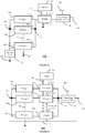
- Figure 8 shows a RF amplifier 400 which includes multiple common-emitter stages or branches.
- An amplifier input 406 may be connected to a first CE stage 402a, a second CE stage 402b and an n th CE stage 402c.
- a resonant circuit 424 may be connected between the amplifier input 406 and a ground 412.
- the ground 412 may also be connected to each of the CE stages 402a, 402b and 402c.
- the outputs of each of the CE stages 404a, 404b, and 404c may be connected to the common collector node 408 and an input to a common-base stage 418.
- the common-base stage 418 output may be connected to an output stage 420.
- the output stage 420 may be connected to the supply rail.
- the output stage may be connected the amplifier output 410.
- the RF amplifier may cancel the third-order harmonic distortion by biasing each of the second CE stage 402b to n th CE stage 402c such that the IM3 distortion currents are in antiphase to the IM3 distortion current of the first CE stage 402a as described earlier for the RF amplifiers 100, 200 and 300.
- the IM3 distortion due to direct mixing may be reduced over a wider range of bias voltages then for just two CE stages.
- the CB stage 418 may allow operation at higher voltages as described for RF amplifier 300.
- the resonant circuit 424 may cancel 2 nd harmonic distortion components by shorting the input voltage as described for RF amplifier 200.
- Figure 9 shows a RF amplifier 500 which includes multiple common-emitter stages and multiple common-base stages.
- An amplifier input 506 may be connected to a first CE stage 502a, a second CE stage 502b and an n th CE stage 502c.
- the ground 512 may also be connected to each of the CE stages 502a, 502b and 502c.
- the outputs of each of the CE stages 504a, 504b, and 504c may be connected to the input of a respective common-base stage 518a, 518b, and 518c.
- the outputs of each of the common-base stages 518a, 518b, and 518c may be connected to a common collector node 508 and the output stage 520.
- the output stage 520 may be connected to the supply rail 514.
- the output stage 520 may be connected the amplifier output 510.
- the RF amplifier 500 may cancel the third-order harmonic distortion by biasing each of the second CE stage 502b to n th CE stage 502c such that the IM3 distortion currents are in antiphase to the IM3 distortion current of the first CE stage 502a as described earlier for the RF amplifiers 100, 200 and 300.
- the CB stages 518a, 518b, 518c may allow operation at higher voltages as described for RF amplifier 300 and the collector currents are summed after the CB stages. The advantage of such an arrangement is that each CB stage can be properly scaled per branch with respect to the bias current operating point of its respective CE stage. This may result in a more balanced load of the different CE stages or branches which may further improve the linearity of the RF amplifier.
- Figure 10 shows example implementations of the CE stage, CB stage, Resonant circuit, and Output stage which may be used for example in RF amplifiers 400 and 500.
- Figure 10a shows a common-emitter stage 600 including a bias circuit 608, a bipolar NPN transistor T1 arranged in a degenerative emitter configuration together with an emitter degeneration resistance R e , and an AC coupling capacitor C1.
- the CE stage 600 has an input 602 connected to a first terminal of capacitance C1, a second terminal of capacitance C1 may be connected to the base of NPN transistor T1.
- the bias circuit 608 may be connected to the base of transistor T1.
- the collector of transistor T1 may be connected to the output 604 of the CE stage 600.
- the emitter degeneration resistance R e may be connected between the emitter of transistor T1 and ground 606.
- RF amplifier 400 and 500 may use two or more common-emitter stages 600 to reduce IM3 distortion by biasing the transistor in each common-emitter stage differently and dimensioning the respective transistor T1 and resistor Re in each stage according to values that satisfy equation 9 within 10% as described for the RF amplifier 100. This may allow IM3 distortion to be reduced in bipolar RF amplifiers operating at high frequency.
- Figure 10b shows a common-emitter stage 600' including a bias circuit 608', a bipolar NPN transistor T1' arranged in a degenerative emitter configuration together with an emitter degeneration resistance R e , and an AC coupling capacitor C1.
- the CE stage 600' has an input 602' connected to a first terminal of capacitance C1', a second terminal of capacitance C1' may be connected to the base of NPN transistor T1'.
- the collector of transistor T1' may be connected to the output 604' of the CE stage 600'.
- the emitter degeneration resistance R e ' may be connected between the emitter of transistor T1' and ground 606.
- a capacitance Cbe_ext may be connected between the base of transistor T1' and the emitter of transistor T1'.
- An RF amplifier may use two or more common-emitter stages 600' to reduce IM3 distortion by biasing the transistor in each common-emitter stage differently. Having a degenerative emitter may allow the derivative superposition principle to be used in an RF bipolar amplifier.
- capacitance Cbe_ext may compensate for the different phase delays of the IM3 currents at high frequency ( f o > f T / ⁇ ). This may allow IM3 distortion to be reduced in bipolar RF amplifiers operating at high frequency.
- Figure 10c shows an example common-emitter stage 600" including a bias circuit 608", a bipolar NPN transistor T1” arranged in a degenerative emitter configuration together with an emitter degeneration resistance R e ", and an AC coupling capacitor C1".
- the CE stage 600" has an input 602" connected to a first terminal of capacitance C1", a second terminal of capacitance C1" may be connected to the base of NPN transistor T1".
- the collector of transistor T1" may be connected to the output 604" of the CE stage 600'.
- the emitter degeneration resistance R e " may be connected between the emitter of transistor T1" and ground 606.
- a capacitance Ce may be connected between the emitter of transistor T1" and ground 606.
- An RF amplifier may use two or more common-emitter stages 600" to reduce IM3 distortion by biasing the transistor in each common-emitter stage differently. Having a degenerative emitter configuration may allow the derivative superposition principle to be used in an RF bipolar amplifier. Alternatively or in addition to dimensioning transistor T1" and resistance Re" according to equation 9, capacitance Ce may compensate for the different phase delays of the IM3 currents at high frequency ( f o > f T/ ⁇ ). This may allow IM3 distortion to be reduced in bipolar RF amplifiers operating at high frequency.
- Figure 10d shows an example common-base stage 610 including a transistor T2' and a capacitance C4' connected between the base of transistor T2' and ground 606.
- Input 612 is connected to the emitter of the transistor T2' and output 614 is connected to the collector of the transistor T2'.
- the bias input 616 is connected to the base of transistor T2'.
- Figure 10e shows an example output stage 620 including a choke inductance L and AC coupling capacitor Cout.
- Inductor L is connected between a supply rail 624 and the input 622.
- the AC coupling capacitor Cout is connected between the input 622 and the output 626. and a capacitance C4' connected between the base of transistor T2' and ground 606.
- Figure 10f shows an example resonance circuit 632 including a series arrangement of an inductance Lres and capacitor Cres between an input 632 and ground 606.
- Lres and Cres may be fixed or variable.
- the circuits and modifications described herein may be applied for the linearization of high frequency RF amplifiers using bipolar devices.
- the RF amplifiers can be Low-Noise Amplifiers or Power Amplifiers, which are used for the reception and transmission of wireless signals respectively.
- RF bipolar amplifiers working in class A or AB, whose overall linearity is (mainly) affected by the exponential distortion.
- the RF amplifiers may be implemented as integrated circuits using any suitable technology. For example SiGe BiCMOS technology may be used.
- Example RF amplifiers described herein may be included in wireless LAN transceivers, mobile phones, base stations in cellular networks, and wireless backhaul systems.
- the RF amplifiers described in the examples use NPN transistors but it will be appreciated that in other examples, PNP bipolar transistors or a combination of PNP and NPN transistors may be used. Some embodiments of the RF amplifiers may operate at frequencies in the range of a few hundred MHz. Some embodiments of the RF amplifiers may operate at frequencies in the range tens of GHz. It will be appreciated that the RF amplifiers described herein may be suitable for amplifying RF signal frequencies greater than a few hundred MHz.
- An RF amplifier including an input, an output, a parallel arrangement of a first branch and at least one further branch, each branch comprising a bipolar transistor in a degenerative emitter configuration having a base coupled to the input, a collector coupled to a common collector node, and an emitter degeneration impedance arranged between the emitter and a common rail.
- the common collector node is coupled to the output, the base of the first branch bipolar transistor is biased at a first bias voltage and the base of the at least one further branch bipolar transistor is biased at a bias voltage offset from the first bias voltage.
- a IM3 distortion current output by the first branch bipolar transistor is in antiphase to a IM3 distortion current output by the at least one further branch bipolar transistor.
Landscapes
- Engineering & Computer Science (AREA)
- Power Engineering (AREA)
- Microelectronics & Electronic Packaging (AREA)
- Physics & Mathematics (AREA)
- Nonlinear Science (AREA)
- Amplifiers (AREA)
Abstract
Description
- This disclosure relates to Radio-Frequency (RF) Amplifiers implemented with bipolar transistors.
- RF amplifiers typically have components with non-linear behaviour which may result in distortion of an incoming signal due to unwanted harmonics resulting from the mixing of different frequencies. In particular third-order intermodulation distortion (IM3) in bipolar amplifiers is harmful as it causes interference with the adjacent transmission channels. This distortion may be significant due to the exponential voltage-to-current transfer of bipolar devices. The IM3 distortion in general is caused by direct mixing of the input components through the third-order power-series coefficient, denoted K3, of the exponential nonlinearity, and indirect mixing of the input components with the second-order components at baseband (IM2) and 2nd harmonic (HD2) frequencies.
- Techniques have been proposed to reduce the effect of the IM3 distortion to linearize the behaviour of an RF amplifier. For example in "RF Amplifier Design Techniques for Linearity and Dynamic Range" - PhD thesis M.P. van der Heijden, published 2005, TU Delft. Out-of-Band matching makes use of both direct and indirect mixing to obtain the IM3 cancellation and can use a single common-emitter (CE) stage. However it is still desirable to further improve the linearity of RF bipolar amplifiers.
- Various aspects of the disclosure are defined in the accompanying claims. In a first aspect there is defined an RF amplifier comprising an input, an output, a parallel arrangement of a first branch and at least one further branch, each branch comprising a bipolar transistor in a degenerative emitter configuration having a base coupled to the input, a collector coupled to a common collector node, and an emitter degeneration impedance arranged between the emitter and a common rail; wherein the common collector node is coupled to the output, the base of the first branch bipolar transistor is biased at a first bias voltage and the base of the at least one further branch bipolar transistor is biased at a bias voltage offset from the first bias voltage and wherein in operation a IM3 distortion current output by the first branch bipolar transistor is in antiphase to a IM3 distortion current output by the at least one further branch bipolar transistor.
- In embodiments, the RF amplifier may further comprise a resonant circuit coupled between the input and the common rail. The resonant circuit comprises a series arrangement of an inductance and a capacitance. The inductance and capacitance may have a variable value.
- In embodiments, the common rail may be a ground.
- In embodiments of the RF amplifier, the value of the respective emitter degeneration impedance in each branch is within 10 percent of the ratio of the transit time and the base emitter junction capacitance of the respective bipolar transistor, and wherein the phase of the IM3 distortion current is independent of the bias voltage.
- In embodiments of the RF amplifier, each branch may comprise a capacitance arranged between the base of the bipolar transistor and the emitter of the bipolar transistor and wherein the phase of the IM3 distortion current is independent of the bias voltage.
- In embodiments of the RF amplifier, the emitter degeneration impedance in each branch may comprise a resistance in parallel with a capacitance and wherein the phase of the IM3 distortion current is independent of the bias voltage.
- In embodiments of the RF amplifier, each of the first branch and the at least one further branch may further comprise an AC coupling capacitor arranged between the input and the respective base of the first branch and at least one further branch bipolar transistors.
- Embodiments of the RF amplifier may further comprise an output stage comprising a RF choke arranged between a supply rail and the common collector node, and a capacitance arranged between the common collector node and the output.
- In embodiments of the RF amplifier, the bipolar transistors may be NPN transistors.
- In embodiments of the RF amplifier, each branch may comprise a respective bias circuit coupled to the base of the respective bipolar transistor and wherein the bias circuit comprises a gyrator.
- The gyrator may comprise a NPN bipolar transistor, a first resistance arranged between a supply voltage rail and the collector, a second resistance arranged between the collector and the base and a capacitance arranged between the base and a ground rail.
- Embodiments of the RF amplifier may further comprise a common-base stage comprising a bipolar transistor having an emitter coupled to the common collector node, a collector coupled to the amplifier output, and a base connected to a common-base bias circuit.
- In embodiments, the RF amplifier may comprise a first common-base stage comprising a first common-base stage bipolar transistor having an emitter coupled to the first branch, a collector coupled to the common collector node, and a base connected to a common-base bias circuit, and at least one further common-base stage comprising at least one further common-base stage bipolar transistor having an emitter coupled to the at least one further branch, a collector coupled to the common collector node, and a base connected to the common-base bias circuit.
- Embodiments of the RF amplifier may be configured as a class A or class AB amplifier.
- Embodiments of the RF amplifier may be included in wireless local area network (WLAN) receivers.
- In the figures and description like reference numerals refer to like features. Embodiments are now described in detail, by way of example only, illustrated by the accompanying drawings in which:
-
Figure 1 shows a RF bipolar amplifier according to an embodiment. -
Figure 2 shows a small signal model of one branch of the RF bipolar transistor offigure 1 . -
Figure 3 illustrates a RF bipolar amplifier according to an embodiment. -
Figure 4a shows a graph of third-order output power intercept point (OIP3) versus varying bias for the low and high IM3 spectral frequency components for the RF amplifier offigure 3 . -
Figure 4b shows a graph of OIP3 versus varying bias for the low and high IM3 frequency components for a bipolar amplifier with incorrectly dimensioned amplifier branches. -
Figure 5 shows a RF bipolar amplifier according to an embodiment. -
Figure 6a illustrates an example bias circuit used in a common-emitter stage. -
Figure 6b shows an example bias circuit used in a common-emitter stage. -
Figure 7 shows a comparison of OIP3 versus varying bias for the RF amplifier offigure 3 and a known RF amplifier with out-of-band matching for improved linearization. -
Figure 8 shows a RF bipolar amplifier according to an embodiment. -
Figure 9 illustrates a RF bipolar amplifier according to an embodiment. -
Figure 10a illustrates an example common-emitter stage used in embodiments of the RF bipolar amplifier. -
Figure 10b illustrates an example common-emitter stage used in embodiments of the RF bipolar amplifier. -
Figure 10c illustrates an example common-emitter stage used in embodiments of the RF bipolar amplifier. -
Figure 10d illustrates an example common-base stage used in embodiments of the RF bipolar amplifier. -
Figure 10e illustrates an example output matching stage used in embodiments of the RF bipolar amplifier. -
Figure 10f illustrates an example resonant circuit used in embodiments of the RF bipolar amplifier. -
Figure 1 shows aRF amplifier 100 which includes aninput 106, anoutput 110, and afirst amplifier branch 102a arranged in parallel with asecond amplifier branch 102b. Thefirst amplifier branch 102a andsecond amplifier branch 102b may also be referred to as a common-emitter (CE) stage. - The
first amplifier branch 102a includes a first bipolar NPN transistor T1 a arranged in a degenerative emitter configuration together with a first emitter degeneration impedance Zea. The base of the bipolar NPN transistor T1a may be connected to theinput 106. The emitter of the first bipolar NPN transistor T1a may be connected to a first terminal of the emitter degeneration impedance Zea. A second terminal of the emitter degeneration impedance Zea may be connected to acommon rail 112 which may be a ground. The collector of the bipolar NPN transistor T1a may be connected to acommon collector node 108. - The
second amplifier branch 102b includes a second bipolar NPN transistor T1b arranged in a degenerative emitter configuration together with a second emitter degeneration impedance Zeb. The base of the second bipolar NPN transistor T1b may be connected to theinput 106. The emitter of the second bipolar NPN transistor T1b may be connected to a first terminal of the emitter degeneration impedance Zeb. A second terminal of the emitter degeneration impedance Zeb may be connected to acommon rail 112 which may be a ground. The collector of the bipolar NPN transistor T1b may be connected to thecommon collector node 108. - The
common collector node 108 may be connected to theamplifier output 110. Abias circuit 104 may be connected to the base of the first bipolar transistor T1a and the second bipolar transistor T1b. - In operation, the
RF amplifier 100 may receive a signal on the input from asignal source 114. The total output current is the sum of the collector currents from the first bipolar transistor T1a and the second bipolar transistor T1b. Thebias circuit 104 may bias the bases of the first NPN transistor T1a and the second NPN transistor T1b such that there is a voltage offset between them. - The first NPN transistor T1a and the second NPN transistor T1b are degenerated and biased in such a way that their individual K3 coefficients are equal in magnitude but have opposite sign. In this way, the overall K3 coefficient can be set equal to zero. Note however, that the bases of T1a and T1b need to be terminated in a low impedance at the second-harmonic (H2) and at baseband (IM2) frequencies in order to avoid unwanted IM3 terms from additional indirect mixing at the base-emitter junction.
- The nonlinear IM3 currents in the two degenerated CE stages need to have an equal magnitude and opposite phase to achieve an overall IM3 cancellation. To accomplish this over a wide biasing range, the maximum (positive sign) and minimum (negative sign) of the third-order Taylor coefficient as a function of base-emitter voltage has to be found. By biasing the first CE stage for the maximum (positive sign) third-order Taylor coefficient and the other CE stage for the minimum (negative sign) third-order Taylor coefficient, the direct mixing terms may be cancelled if these are made equal in magnitude.
- The third-order Taylor coefficient of the emitter-degenerated collector current can be described as:


- When (2), (3) and (4) are valid, the Vbe-Ic relationship approximates a quadratic function for a part of the bias range. By including a degenerative emitter, the principle of derivative superposition to reduce IM3 distortion previously only considered suitable for FET amplifiers may be applied to bipolar RF amplifiers.
- At operating frequencies f 0 well below f T, typically f o<f T/β, where f T is the transition frequency at which the current gain (P) drops to 1, the transistor displays an approximately ohmic behaviour. At operating frequencies closer to f T (f o>f T/β), the diffusion capacitance, resulting from the forward base-emitter transit time τ f , and the base-emitter depletion capacitance may also affect the nonlinear third-order intermodulation.
-
Figure 2 shows asmall signal model 150 of one of a single branch common-emitter stage 102a. With reference tofigure 2 , the second order non-linear collector current i c,NL2 generated by the exponential base-emitter relation:
- Where νbe is the base-emitter voltage and K2gm is the second-order Taylor coefficient of the exponential collector current to base-emitter voltage relationship.
- And the tracking non-linear currents, such as the exponential base current ib,NL2 and the capacitive current from the base-emitter diffusion capacitance icde, NL2 are respectively:


- Where β is the current gain, and τf is the forward base-emitter transit time.
- These currents interact with the input terminations and with the base-emitter diffusion and depletion capacitances, generating second-order voltages. This can be described analytically by the function:

- Where Cπ = Cde + Cje is the total base-emitter capacitance, in which Cde = τf gm is the diffusion capacitance and Cje is the depletion capacitance.
- B(s) represents the transfer function from the second-order non-linear currents, generated by the exponential distortion, to the second-order base-emitter voltage. This function B(s) may introduce different phase shifts to the second-order voltages, mainly the 2nd harmonic voltages, depending on the values of Zb, Ze, and gm. However, if we set the emitter degeneration impedance and the base-emitter junction capacitance, such that:

- The zero and the pole of B(s) fall on top of each other, and so no phase shift is introduced. This is true when Zb/β «Ze.
- At operating frequencies where f o>f T/β, the IM3 collector currents of the two branches may have different phases, due to the shift introduced by reactive components, such as the base-emitter diffusion and depletion capacitances. Signals that are generated by indirect mixing inside each transistor T1a, T1b, may experience different phase shifts, due to the different operating points of the two transistors.
- However, by dimensioning the transistors T1a and T1b and choosing values of Zea and Zeb to satisfy equations (2) - (4), and (9) for both the CE-
stage branches -
Figure 3 shows aRF amplifier 200 according to an embodiment. A first amplifier branch or CE-stage 202a includes a first bipolar NPN transistor T1a' arranged in a degenerative emitter configuration together with a first emitter degeneration impedance Zea', and an AC coupling capacitor C1a. Aninput 206 may be connected to a first terminal of an AC coupling capacitor C1a. The base of the bipolar NPN transistor T1a' may be connected to a second terminal of the AC coupling capacitor C1a. The base of the bipolar NPN transistor T1a' may be connected to a firstbias supply rail 204a. The emitter of the first bipolar NPN transistor T1a' may be connected to a first terminal of the emitter degeneration impedance Zea'. A second terminal of the emitter degeneration impedance Zea' may be connected to acommon rail 212 which may be a ground. The collector of the bipolar NPN transistor T1a' may be connected to acommon collector node 208. - A
second amplifier branch 202b includes a second bipolar NPN transistor T1b' arranged in a degenerative emitter configuration together with a second emitter degeneration impedance Zeb', and an AC coupling capacitor C1b. Aninput 206 may be connected to a first terminal of an AC coupling capacitor C1b. The base of the bipolar NPN transistor T1b' may be connected to a second terminal of the AC coupling capacitor C1b. The base of the bipolar NPN transistor T1b' may be connected to a secondbias supply rail 204b. The emitter of the second bipolar NPN transistor T1b' may be connected to a first terminal of the emitter degeneration impedance Zeb'. A second terminal of the emitter degeneration impedance Zeb' may be connected to acommon rail 212 which may be a ground. The collector of the bipolar NPN transistor T1b' may be connected to acommon collector node 208. - An
amplifier output stage 220 may include an output AC coupling capacitor C3 and a choke inductance L3. Thecommon collector node 208 may be connected to a first terminal of the output AC coupling capacitor C3. A second terminal of the output AC coupling capacitor C3 may be connected to theamplifier output 210. The choke inductance L3 may be connected between thecommon collector node 308 and asupply rail 214. - A
resonant circuit 216 may include a series arrangement of an inductor L1 and a capacitor C2 connected between theamplifier input 206 and thecommon rail 212. The inductor L1 and the capacitor C2 may be variable or fixed. In other examples, different components may be used to form a resonant circuit. - In operation, the
amplifier input 206 may receive an input signal from asignal source 216 represented by a voltage source Vs in series with a resistance Rs. Theamplifier output 210 may be connected to a load represented as a load resistance RL. The total output current provided is the sum of the collector currents from the first bipolar transistor T1a and the second bipolar transistor T1b. The bases of transistors T1a' and T1b' are biased at different voltages applied to the firstbias supply rail RF amplifier 100. - By using this relation of equations (2)-(4), and (9) for both the branches, the two IM3 currents are exactly in anti-phase, resulting in effective cancellation of the K3 coefficient. Since the IM3 currents are in antiphase, the RF amplifier may have improved linearity as the direct mixing contribution to the IM3 current may be cancelled. At the same time, any unwanted IM3 terms generated by indirect mixing may be removed by zeroing the input voltage in the out-of-band frequencies. For the Baseband frequencies, this may be achieved by using biasing circuits that present a low output impedance Zout to the base node where

resonant circuit 216 between theinput 206 and thecommon rail 212, the 2nd harmonic frequencies at theinput 206 may be shorted to thecommon rail 212. By shorting the 2nd harmonic frequencies, the linearity of thebipolar amplifier 200 may be significantly improved. When both baseband and 2nd harmonic voltages are nullified, no additional IM3 distortion may be generated by indirect mixing mechanisms. -
Figure 4a shows agraph 250 of the results of simulation of theRF amplifier circuit 200 when a two-tone input frequency is applied. Thex-axis 252 shows the quiescent collector bias current on a logarithmic scale in amps up to 50 mA resulting from a sweep of the input biasing voltage. The y-axis 254 is a linear scale showing the value of the third-order output power intercept point (OIP3) in dBm ranging from 0 to 70. Theline 256 shows the variation in OIP3 for the higher IM3 harmonic (OIP3H).Line 258 shows the variation in OIP3 for the lower IM3 harmonic (OIP3L). As can be seen the OIP3 variation with biasing current is virtually identical in each case. -
Figure 4b shows agraph 260 of RF amplifier when the transistors are dimensioned such that the base-emitter depletion capacitance is 20% larger than the optimum value for linearity i.e. Cje = 1.2x τf /Ze and there is no resonant circuit to short the input voltage in the 2nd Harmonic band. Thex-axis 262 shows the quiescent collector bias current on a logarithmic scale in amps up to 50 mA resulting from a sweep of the input biasing voltage. The y-axis 264 shows the value of the third-order output power intercept point (OIP3) in dBm ranging from 0 to 70. Theline 266 shows the variation in OIP3 for the higher IM3 harmonic (OIP3H).Line 268 shows the variation in OIP3 for the lower IM3 harmonic (OIP3L). When the reactive part of the transistors is not compensated, the phases of the two IM3 currents are not aligned, yielding a degradation of the OIP3 figure. -
Figure 5 shows aRF amplifier 300 according to an embodiment. A first common-emitter branch 302a may include afirst bias circuit 304a, a first bipolar NPN transistor T1a" arranged in a degenerative emitter configuration together with a first emitter degeneration impedance Zea", and an AC coupling capacitor C1a'. Anamplifier input 306 may be connected to a first terminal of an AC coupling capacitor C1a'. The base of the bipolar NPN transistor T1a" may be connected to a second terminal of the AC coupling capacitor C1a'. The base of the bipolar NPN transistor T1a" may be connected to thefirst bias circuit 304a. The emitter of the first bipolar NPN transistor T1a" may be connected to a first terminal of the emitter degeneration impedance Zea". A second terminal of the emitter degeneration impedance Zea" may be connected to acommon rail 312 which may be a ground. The collector of the bipolar NPN transistor T1a" may be connected to acommon collector node 308. - A second common-
emitter branch 302b may include a second bipolar NPN transistor T1b" arranged in a degenerative emitter configuration together with a second emitter degeneration impedance Zeb", and an AC coupling capacitor C1b'. Theamplifier input 306 may be connected to a first terminal of an AC coupling capacitor C1b'. The base of the bipolar NPN transistor T1b" may be connected to a second terminal of the AC coupling capacitor C1b. The base of the bipolar NPN transistor T1b' may be connected to thesecond bias circuit 304b. The emitter of the second bipolar NPN transistor T1b" may be connected to a first terminal of the emitter degeneration impedance Zeb". A second terminal of the emitter degeneration impedance Zeb" may be connected to acommon rail 312 which may be a ground. The collector of the bipolar NPN transistor T1b' may be connected to acommon collector node 308. - A common-base (CB)
stage 318 may include a third NPN transistor T2, and a capacitor C4.Thecommon collector node 308 may be connected to an emitter of a third NPN transistor T2. The collector of the third NPN transistor T2 may be connected to a first terminal of an output AC coupling capacitor C3'. A second terminal of the output AC coupling capacitor C3' may be connected to theamplifier output 310. A choke inductance L3' may be connected between the collector of the third NPN transistor T2 and asupply rail 314. A common-base bias circuit 316 may be connected to the base of the third NPN transistor T2. The capacitor C4 may be connected between the base of the third NPN transistor T2 and theground rail 312 to short the fundamental frequency.Bias circuit 316 for the common-base stage transistor T2 may be wide-band and low-ohmic output impedance which may be implemented for example using an emitter-follower circuit. - In operation, the
amplifier input 306 may receive an input signal. The total output current is the sum of the collector currents from the first bipolar transistor T1a" and the second bipolar transistor T1b". The bases of transistors T1a" and T1b" are biased at different voltages applied byrespective bias circuits RF amplifiers input 306 and thecommon rail 312 to short the 2nd Harmonic frequencies. - The cascode configuration obtained by adding the third transistor T2 reduces the feedback effect of the base-collector capacitance (Cbc) of the two transistors T1a", T1b", which ensures the output collector currents are actually summed at the
common collector node 308. At the same time, the transistor T2 configured as a common-base stage, can sustain a higher output voltage swing due to the cascode arrangement, resulting in a higher peak output power. - By using the relation of equation 9 for both the branches, the two IM3 currents are exactly in anti-phase, resulting in effective cancellation of the K3 coefficient. Consequently the direct mixing contribution to the IM3 current is cancelled, which may improve the linearity of the amplifier. At the same time, the IM3 terms generated by indirect mixing at the base of T1a" and T1b" at the out-of-band frequencies may be reduced, by zeroing the input voltage at the out-of-band frequencies. This may further improve the linearity of the RF amplifier. For the Baseband frequencies, this may be achieved for example by using the biasing circuits shown in
figure 6a and 6b which implements a gyrator to create an active inductor circuit. The gyrator requires a smaller chip area than a physical inductor. -
Figure 6a shows abiasing circuit 320. A first resistance R1 may be connected between asupply rail 314 and the collector of a NPN bias transistor Tbias. A second resistance R2 may be connected between the collector and base of the bias transistor Tbias. A capacitance Cbias may be connected between the base of the bias transistor Tbias and aground rail 312. The collector of the bias transistor Tbias is connected to thebias circuit output 322. - This circuit implements a gyrator. The output impedance can be written as:

- At the same time, it provides isolation from the RF circuit path by offering a high output impedance at RF: assuming: R2 » 1/gm → Zout,RF ≈ sR 2 Clgm (inductive)
- The
bias circuit 320 may be used to implementbias circuits bias circuits - The
bias circuit 320 has an important advantage over the use of an inductor for biasing purposes: when two or more transistors are used to implement the RF amplifiers,bias circuit 350 occupies a much lower die area, and the biasing circuitry can be positioned on-chip, very close to the RF circuitry. Moreover,bias circuit 320 provides on-chip base-band decoupling for the input of the amplifier. -
Figure 6b shows abiasing circuit 340 which also implements a gyrator. A first resistance RB1 is connected between avoltage reference 342 and the base of a first bias transistor BT1, the collector of the first bias transistor BT1 is connected to asupply rail 314. The emitter of the first bias transistor BT1 is connected to the bias circuit output 322'. A second bias resistor RB2 is connected between the base of the second bias transistor BT2 and the bias circuit output 322'. - When connected to a CE stage, transistor BT1 may conduct current to cancel avalanche current generated in the CE stage, which will predominantly occur under load mismatch conditions. Transistor BT1 may provide the exact amount of base current needed by a connected CE stage, without wasting power when a low signal amplitude is present. The value of the resistors RB1 and RB2 are chosen in such a way that together with the base-to-emitter capacitances of BT1 and BT2 they prevent unwanted RF currents in these transistors, thereby eliminating the need for any inductors similarly to the
gyrator circuit 320. Other bias circuits which may be used for biasing the common-emitter stages are described in European patent application16177378.3 -
Figure 7 shows a graph 360 of the OIP3 performance for theRF amplifier 300 compared to an RF bipolar amplifier using only out-of-band matching when a two-tone input frequency is applied. The x-axis 362 shows the biasing quiescent collector current on a logarithmic scale in amps up to 80 mA resulting from a sweep of the input biasing voltage. The y-axis 364 is a linear scale showing the value of the third-order output power intercept point (OIP3) in dBm ranging from 0 to 80. The line 366 shows the variation in OIP3 forRF power amplifier 300.Line 408 shows the variation in OIP3 for the known RF amplifier. As can be seen, the OIP3 value is higher for theRF power amplifier 300 for bias current levels below approximately 4 mA. -
Figure 8 shows aRF amplifier 400 which includes multiple common-emitter stages or branches. Anamplifier input 406 may be connected to afirst CE stage 402a, asecond CE stage 402b and an nth CE stage 402c. Aresonant circuit 424 may be connected between theamplifier input 406 and aground 412. - The
ground 412 may also be connected to each of theCE stages CE stages common collector node 408 and an input to a common-base stage 418. The common-base stage 418 output may be connected to anoutput stage 420. Theoutput stage 420 may be connected to the supply rail. The output stage may be connected theamplifier output 410. The RF amplifier may cancel the third-order harmonic distortion by biasing each of thesecond CE stage 402b to nth CE stage 402c such that the IM3 distortion currents are in antiphase to the IM3 distortion current of thefirst CE stage 402a as described earlier for theRF amplifiers CB stage 418 may allow operation at higher voltages as described forRF amplifier 300. Theresonant circuit 424 may cancel 2nd harmonic distortion components by shorting the input voltage as described forRF amplifier 200. -
Figure 9 shows aRF amplifier 500 which includes multiple common-emitter stages and multiple common-base stages. Anamplifier input 506 may be connected to afirst CE stage 502a, asecond CE stage 502b and an nth CE stage 502c. Theground 512 may also be connected to each of theCE stages CE stages base stage base stages common collector node 508 and theoutput stage 520. Theoutput stage 520 may be connected to thesupply rail 514. Theoutput stage 520 may be connected theamplifier output 510. TheRF amplifier 500 may cancel the third-order harmonic distortion by biasing each of thesecond CE stage 502b to nth CE stage 502c such that the IM3 distortion currents are in antiphase to the IM3 distortion current of thefirst CE stage 502a as described earlier for theRF amplifiers RF amplifier 300 and the collector currents are summed after the CB stages. The advantage of such an arrangement is that each CB stage can be properly scaled per branch with respect to the bias current operating point of its respective CE stage. This may result in a more balanced load of the different CE stages or branches which may further improve the linearity of the RF amplifier. -
Figure 10 shows example implementations of the CE stage, CB stage, Resonant circuit, and Output stage which may be used for example inRF amplifiers -
Figure 10a shows a common-emitter stage 600 including abias circuit 608, a bipolar NPN transistor T1 arranged in a degenerative emitter configuration together with an emitter degeneration resistance Re, and an AC coupling capacitor C1. TheCE stage 600 has aninput 602 connected to a first terminal of capacitance C1, a second terminal of capacitance C1 may be connected to the base of NPN transistor T1. Thebias circuit 608 may be connected to the base of transistor T1. The collector of transistor T1 may be connected to theoutput 604 of theCE stage 600. The emitter degeneration resistance Re may be connected between the emitter of transistor T1 andground 606.RF amplifier emitter stages 600 to reduce IM3 distortion by biasing the transistor in each common-emitter stage differently and dimensioning the respective transistor T1 and resistor Re in each stage according to values that satisfy equation 9 within 10% as described for theRF amplifier 100. This may allow IM3 distortion to be reduced in bipolar RF amplifiers operating at high frequency. -
Figure 10b shows a common-emitter stage 600' including a bias circuit 608', a bipolar NPN transistor T1' arranged in a degenerative emitter configuration together with an emitter degeneration resistance Re, and an AC coupling capacitor C1. The CE stage 600' has an input 602' connected to a first terminal of capacitance C1', a second terminal of capacitance C1' may be connected to the base of NPN transistor T1'. The collector of transistor T1' may be connected to the output 604' of the CE stage 600'. The emitter degeneration resistance Re' may be connected between the emitter of transistor T1' andground 606. A capacitance Cbe_ext may be connected between the base of transistor T1' and the emitter of transistor T1'. An RF amplifier may use two or more common-emitter stages 600' to reduce IM3 distortion by biasing the transistor in each common-emitter stage differently. Having a degenerative emitter may allow the derivative superposition principle to be used in an RF bipolar amplifier. Alternatively or in addition to dimensioning transistor T1' and resistance Re' according to equation 9, capacitance Cbe_ext may compensate for the different phase delays of the IM3 currents at high frequency (f o > f T/β). This may allow IM3 distortion to be reduced in bipolar RF amplifiers operating at high frequency. -
Figure 10c shows an example common-emitter stage 600" including abias circuit 608", a bipolar NPN transistor T1" arranged in a degenerative emitter configuration together with an emitter degeneration resistance Re", and an AC coupling capacitor C1". TheCE stage 600" has aninput 602" connected to a first terminal of capacitance C1", a second terminal of capacitance C1" may be connected to the base of NPN transistor T1". The collector of transistor T1" may be connected to theoutput 604" of the CE stage 600'. The emitter degeneration resistance Re" may be connected between the emitter of transistor T1" andground 606. A capacitance Ce may be connected between the emitter of transistor T1" andground 606. An RF amplifier may use two or more common-emitter stages 600" to reduce IM3 distortion by biasing the transistor in each common-emitter stage differently. Having a degenerative emitter configuration may allow the derivative superposition principle to be used in an RF bipolar amplifier. Alternatively or in addition to dimensioning transistor T1" and resistance Re" according to equation 9, capacitance Ce may compensate for the different phase delays of the IM3 currents at high frequency (f o > fT/β). This may allow IM3 distortion to be reduced in bipolar RF amplifiers operating at high frequency. -
Figure 10d shows an example common-base stage 610 including a transistor T2' and a capacitance C4' connected between the base of transistor T2' andground 606.Input 612 is connected to the emitter of the transistor T2' andoutput 614 is connected to the collector of the transistor T2'. Thebias input 616 is connected to the base of transistor T2'. -
Figure 10e shows anexample output stage 620 including a choke inductance L and AC coupling capacitor Cout. Inductor L is connected between asupply rail 624 and theinput 622. The AC coupling capacitor Cout is connected between theinput 622 and theoutput 626. and a capacitance C4' connected between the base of transistor T2' andground 606. -
Figure 10f shows anexample resonance circuit 632 including a series arrangement of an inductance Lres and capacitor Cres between aninput 632 andground 606. Lres and Cres may be fixed or variable. - The circuits and modifications described herein may be applied for the linearization of high frequency RF amplifiers using bipolar devices. The RF amplifiers can be Low-Noise Amplifiers or Power Amplifiers, which are used for the reception and transmission of wireless signals respectively. In particular, RF bipolar amplifiers working in class A or AB, whose overall linearity is (mainly) affected by the exponential distortion. The RF amplifiers may be implemented as integrated circuits using any suitable technology. For example SiGe BiCMOS technology may be used. Example RF amplifiers described herein may be included in wireless LAN transceivers, mobile phones, base stations in cellular networks, and wireless backhaul systems. The RF amplifiers described in the examples use NPN transistors but it will be appreciated that in other examples, PNP bipolar transistors or a combination of PNP and NPN transistors may be used. Some embodiments of the RF amplifiers may operate at frequencies in the range of a few hundred MHz. Some embodiments of the RF amplifiers may operate at frequencies in the range tens of GHz. It will be appreciated that the RF amplifiers described herein may be suitable for amplifying RF signal frequencies greater than a few hundred MHz.
- An RF amplifier is described including an input, an output, a parallel arrangement of a first branch and at least one further branch, each branch comprising a bipolar transistor in a degenerative emitter configuration having a base coupled to the input, a collector coupled to a common collector node, and an emitter degeneration impedance arranged between the emitter and a common rail. The common collector node is coupled to the output, the base of the first branch bipolar transistor is biased at a first bias voltage and the base of the at least one further branch bipolar transistor is biased at a bias voltage offset from the first bias voltage. In operation of the RF amplifier a IM3 distortion current output by the first branch bipolar transistor is in antiphase to a IM3 distortion current output by the at least one further branch bipolar transistor.
- Although the appended claims are directed to particular combinations of features, it should be understood that the scope of the disclosure of the present invention also includes any novel feature or any novel combination of features disclosed herein either explicitly or implicitly or any generalisation thereof, whether or not it relates to the same invention as presently claimed in any claim and whether or not it mitigates any or all of the same technical problems as does the present invention.
- Features which are described in the context of separate embodiments may also be provided in combination in a single embodiment. Conversely, various features which are, for brevity, described in the context of a single embodiment, may also be provided separately or in any suitable sub combination.
- The applicant hereby gives notice that new claims may be formulated to such features and/or combinations of such features during the prosecution of the present application or of any further application derived therefrom.
- For the sake of completeness it is also stated that the term "comprising" does not exclude other elements or steps, the term "a" or "an" does not exclude a plurality, a single processor or other unit may fulfil the functions of several means recited in the claims and reference signs in the claims shall not be construed as limiting the scope of the claims.
Claims (15)
- An RF amplifier comprising:an input,an output,a parallel arrangement of a first branch and at least one further branch, each branch comprising a bipolar transistor in a degenerative emitter configuration having a base coupled to the input, a collector coupled to a common collector node, and an emitter degeneration impedance arranged between the emitter and a common rail;wherein the common collector node is coupled to the output, the base of the first branch bipolar transistor is biased at a first bias voltage and the base of the at least one further branch bipolar transistor is biased at a bias voltage offset from the first bias voltage, and wherein in operation a IM3 distortion current output by the first branch bipolar transistor is in antiphase to a IM3 distortion current output by the at least one further branch bipolar transistor.
- The RF amplifier of claim 1 further comprising a resonant circuit coupled between the input and the common rail.
- The RF amplifier of claim 2 wherein the resonant circuit comprises a series arrangement of an inductance and a capacitance.
- The RF amplifier of claim 3 wherein at least one of the inductance and capacitance has a variable value.
- The RF amplifier of any preceding claim wherein the common rail is a ground.
- The RF amplifier of any preceding claim wherein the value of the respective emitter degeneration impedance in each branch is within 10 percent of the ratio of the transit time and the base emitter junction capacitance of the respective bipolar transistor, and wherein the phase of the IM3 distortion current is independent of the bias voltage.
- The RF amplifier of any preceding claim wherein each branch comprises a capacitance arranged between the base of the bipolar transistor and the emitter of the bipolar transistor and wherein the phase of the IM3 distortion current is independent of the bias voltage.
- The RF amplifier of any preceding claim wherein the emitter degeneration impedance in each branch comprises a resistance in parallel with a capacitance and wherein the phase of the IM3 distortion current is independent of the bias voltage.
- The RF amplifier of any preceding claim wherein each of the first branch and the at least one further branch further comprises an AC coupling capacitor arranged between the input and the respective base of the first branch and the at least one further branch bipolar transistors.
- The RF amplifier of any preceding claim further comprising an output stage comprising a RF choke arranged between a supply rail and the common collector node, and a capacitance arranged between the common collector node and the output.
- The RF amplifier of any preceding claim wherein each branch comprises a respective bias circuit coupled to the base of the respective bipolar transistor and wherein the bias circuit comprises a gyrator.
- The RF amplifier of claim 11 wherein the gyrator comprises a NPN bipolar transistor, a first resistance arranged between a supply voltage rail and the collector, a second resistance arranged between the collector and the base and a capacitance arranged between the base and a ground rail.
- The RF amplifier of any preceding claim further comprising a common-base stage comprising a bipolar transistor having an emitter coupled to the common collector node, a collector coupled to the amplifier output, and a base connected to a common-base bias circuit.
- The RF amplifier of any of claims 1 to 12 further comprising:a first common-base stage comprising a first common-base stage bipolar transistor having an emitter coupled to the first branch, a collector coupled to the common collector node, and a base connected to a common-base bias circuit, andat least one further common-base stage comprising at least one further common-base stage bipolar transistor having an emitter coupled to the at least one further branch, a collector coupled to the common collector node, and a base connected to the common-base bias circuit.
- The RF amplifier of any preceding claim configured as a class A or class AB amplifier.
Priority Applications (2)
| Application Number | Priority Date | Filing Date | Title |
|---|---|---|---|
| EP17150707.2A EP3346608B1 (en) | 2017-01-09 | 2017-01-09 | Rf amplifier |
| US15/865,145 US10284148B2 (en) | 2017-01-09 | 2018-01-08 | RF amplifier |
Applications Claiming Priority (1)
| Application Number | Priority Date | Filing Date | Title |
|---|---|---|---|
| EP17150707.2A EP3346608B1 (en) | 2017-01-09 | 2017-01-09 | Rf amplifier |
Publications (2)
| Publication Number | Publication Date |
|---|---|
| EP3346608A1 true EP3346608A1 (en) | 2018-07-11 |
| EP3346608B1 EP3346608B1 (en) | 2021-05-26 |
Family
ID=57755234
Family Applications (1)
| Application Number | Title | Priority Date | Filing Date |
|---|---|---|---|
| EP17150707.2A Active EP3346608B1 (en) | 2017-01-09 | 2017-01-09 | Rf amplifier |
Country Status (2)
| Country | Link |
|---|---|
| US (1) | US10284148B2 (en) |
| EP (1) | EP3346608B1 (en) |
Families Citing this family (5)
| Publication number | Priority date | Publication date | Assignee | Title |
|---|---|---|---|---|
| SG11202105159SA (en) * | 2019-01-10 | 2021-06-29 | Skyworks Solutions Inc | Apparatus and methods for biasing of power amplifiers |
| JP2020156048A (en) * | 2019-03-22 | 2020-09-24 | 株式会社村田製作所 | Power amplifier circuit |
| US12107550B2 (en) | 2022-04-29 | 2024-10-01 | Avago Technologies International Sales Pte. Limited | Linearization of differential RF power amplifier by bias control using cross-coupling components |
| EP4307563A1 (en) | 2022-07-13 | 2024-01-17 | NXP USA, Inc. | Analog amplitude pre-distortion circuit and method |
| EP4307562A1 (en) * | 2022-07-13 | 2024-01-17 | NXP USA, Inc. | Analog amplitude pre-distortion circuit and method |
Citations (5)
| Publication number | Priority date | Publication date | Assignee | Title |
|---|---|---|---|---|
| US20020113650A1 (en) * | 2001-02-16 | 2002-08-22 | Bonkee Kim | Amplifier and mixer with improved linearity |
| US6744322B1 (en) * | 2002-01-23 | 2004-06-01 | Skyworks Solutions, Inc. | High performance BiFET low noise amplifier |
| EP1978635A1 (en) * | 2007-04-04 | 2008-10-08 | Telefonaktiebolaget LM Ericsson (publ) | Circuitry and method for reducing second and third-order nonlinearities |
| US20090174481A1 (en) * | 2008-01-04 | 2009-07-09 | Qualcomm Incorporated | Multi-linearity mode lna having a deboost current path |
| US20110018635A1 (en) * | 2009-07-23 | 2011-01-27 | Qualcomm Incorporated | Multi-mode low noise amplifier with transformer source degeneration |
Family Cites Families (11)
| Publication number | Priority date | Publication date | Assignee | Title |
|---|---|---|---|---|
| US4472687A (en) * | 1980-12-24 | 1984-09-18 | Tokyo Shibaura Denki Kabushiki Kaisha | Audio power amplifier for supplying electric power to a load by switching of power supply voltage |
| JPS6129526U (en) * | 1984-07-25 | 1986-02-22 | パイオニア株式会社 | balance control circuit |
| JP3600115B2 (en) * | 2000-04-05 | 2004-12-08 | 株式会社東芝 | High frequency circuit and communication system |
| US6727761B1 (en) * | 2002-09-03 | 2004-04-27 | Triquint Semiconductor, Inc. | Resonant bypassed base ballast circuit |
| US7161433B2 (en) * | 2003-06-11 | 2007-01-09 | Mitsubishi Denki Kabushiki Kaisha | High-frequency amplifier |
| US7853235B2 (en) | 2004-02-11 | 2010-12-14 | Qualcomm, Incorporated | Field effect transistor amplifier with linearization |
| JP4756843B2 (en) * | 2004-10-05 | 2011-08-24 | パナソニック株式会社 | Transistor circuit |
| JP4155326B2 (en) * | 2004-11-29 | 2008-09-24 | 株式会社村田製作所 | Semiconductor device and power amplifier |
| JP2006325096A (en) * | 2005-05-20 | 2006-11-30 | Matsushita Electric Ind Co Ltd | High frequency power amplifier |
| KR100614928B1 (en) | 2005-08-17 | 2006-08-25 | 삼성전기주식회사 | Differential Superposition Circuit for Linearization |
| KR101373658B1 (en) * | 2009-12-04 | 2014-03-13 | 한국전자통신연구원 | Power amplifier device |
-
2017
- 2017-01-09 EP EP17150707.2A patent/EP3346608B1/en active Active
-
2018
- 2018-01-08 US US15/865,145 patent/US10284148B2/en active Active
Patent Citations (5)
| Publication number | Priority date | Publication date | Assignee | Title |
|---|---|---|---|---|
| US20020113650A1 (en) * | 2001-02-16 | 2002-08-22 | Bonkee Kim | Amplifier and mixer with improved linearity |
| US6744322B1 (en) * | 2002-01-23 | 2004-06-01 | Skyworks Solutions, Inc. | High performance BiFET low noise amplifier |
| EP1978635A1 (en) * | 2007-04-04 | 2008-10-08 | Telefonaktiebolaget LM Ericsson (publ) | Circuitry and method for reducing second and third-order nonlinearities |
| US20090174481A1 (en) * | 2008-01-04 | 2009-07-09 | Qualcomm Incorporated | Multi-linearity mode lna having a deboost current path |
| US20110018635A1 (en) * | 2009-07-23 | 2011-01-27 | Qualcomm Incorporated | Multi-mode low noise amplifier with transformer source degeneration |
Non-Patent Citations (1)
| Title |
|---|
| M.P. VAN DER HEIJDEN: "PhD thesis", 2005, TU DELFT, article "RF Amplifier Design Techniques for Linearity and Dynamic Range" |
Also Published As
| Publication number | Publication date |
|---|---|
| US10284148B2 (en) | 2019-05-07 |
| US20180198420A1 (en) | 2018-07-12 |
| EP3346608B1 (en) | 2021-05-26 |
Similar Documents
| Publication | Publication Date | Title |
|---|---|---|
| KR100686785B1 (en) | Impedance Matching Network for Nonlinear Circuits | |
| US10284148B2 (en) | RF amplifier | |
| KR101115266B1 (en) | Differential amplifier with active post-distortion linearization | |
| CN101904091A (en) | Low noise and low input capacitance differential MDS LNA | |
| Fong | High-frequency analysis of linearity improvement technique of common-emitter transconductance stage using a low-frequency-trap network | |
| US9276535B2 (en) | Transconductance amplifier | |
| US8803612B1 (en) | Low-noise amplifier with high linearity | |
| KR100427878B1 (en) | Amplifier circuit | |
| KR100861877B1 (en) | Circuit to linearize electronic devices | |
| EP2624448A1 (en) | Low-noise amplifier | |
| US11387796B2 (en) | Power amplifier circuit | |
| Luong et al. | Microwave characteristics of an independently biased 3-stack InGaP/GaAs HBT configuration | |
| US6944438B2 (en) | Transconductance stage and device for communication by Hertzian channel equipped with such a stage | |
| EP2045913A1 (en) | Low noise amplifier and N-mode gain control circuit therefor | |
| US8994451B1 (en) | RF amplifier | |
| De Vreede et al. | " Linearization Techniques at the Device and Circuit Level" | |
| US7345548B2 (en) | Radiofrequency amplifier device, in particular for cellular mobile telephone | |
| Najari et al. | Wideband inductorless LNA employing simultaneous 2 nd and 3 rd order distortion cancellation | |
| US11239798B2 (en) | Distribution mixer | |
| KR100736394B1 (en) | Differential Circuit with Improved Linearity, Differential Amplifier and Mixer Circuit | |
| Verma et al. | Design of a Gain-Stabilized Ka-Band Low Noise Amplifier (LNA) | |
| Visweswaran et al. | A low power UWB-LNA using active dual loop negative feedback in CMOS 0.13 µm | |
| JPH08186455A (en) | Analog and digital portable telephone power amplifier | |
| Kuremyr | A Study on Linearity of Mixers for Homodyne Receivers | |
| El-Khatib et al. | A 0.1-12 GHz fully differential CMOS distributed amplifier employing a feedforward distortion cancellation technique |
Legal Events
| Date | Code | Title | Description |
|---|---|---|---|
| PUAI | Public reference made under article 153(3) epc to a published international application that has entered the european phase |
Free format text: ORIGINAL CODE: 0009012 |
|
| STAA | Information on the status of an ep patent application or granted ep patent |
Free format text: STATUS: THE APPLICATION HAS BEEN PUBLISHED |
|
| AK | Designated contracting states |
Kind code of ref document: A1 Designated state(s): AL AT BE BG CH CY CZ DE DK EE ES FI FR GB GR HR HU IE IS IT LI LT LU LV MC MK MT NL NO PL PT RO RS SE SI SK SM TR |
|
| AX | Request for extension of the european patent |
Extension state: BA ME |
|
| STAA | Information on the status of an ep patent application or granted ep patent |
Free format text: STATUS: REQUEST FOR EXAMINATION WAS MADE |
|
| 17P | Request for examination filed |
Effective date: 20190111 |
|
| RBV | Designated contracting states (corrected) |
Designated state(s): AL AT BE BG CH CY CZ DE DK EE ES FI FR GB GR HR HU IE IS IT LI LT LU LV MC MK MT NL NO PL PT RO RS SE SI SK SM TR |
|
| STAA | Information on the status of an ep patent application or granted ep patent |
Free format text: STATUS: EXAMINATION IS IN PROGRESS |
|
| 17Q | First examination report despatched |
Effective date: 20200123 |
|
| GRAP | Despatch of communication of intention to grant a patent |
Free format text: ORIGINAL CODE: EPIDOSNIGR1 |
|
| GRAJ | Information related to disapproval of communication of intention to grant by the applicant or resumption of examination proceedings by the epo deleted |
Free format text: ORIGINAL CODE: EPIDOSDIGR1 |
|
| GRAP | Despatch of communication of intention to grant a patent |
Free format text: ORIGINAL CODE: EPIDOSNIGR1 |
|
| STAA | Information on the status of an ep patent application or granted ep patent |
Free format text: STATUS: GRANT OF PATENT IS INTENDED |
|
| RAP1 | Party data changed (applicant data changed or rights of an application transferred) |
Owner name: NXP B.V. |
|
| INTG | Intention to grant announced |
Effective date: 20210121 |
|
| GRAS | Grant fee paid |
Free format text: ORIGINAL CODE: EPIDOSNIGR3 |
|
| GRAA | (expected) grant |
Free format text: ORIGINAL CODE: 0009210 |
|
| STAA | Information on the status of an ep patent application or granted ep patent |
Free format text: STATUS: THE PATENT HAS BEEN GRANTED |
|
| AK | Designated contracting states |
Kind code of ref document: B1 Designated state(s): AL AT BE BG CH CY CZ DE DK EE ES FI FR GB GR HR HU IE IS IT LI LT LU LV MC MK MT NL NO PL PT RO RS SE SI SK SM TR |
|
| REG | Reference to a national code |
Ref country code: GB Ref legal event code: FG4D |
|
| REG | Reference to a national code |
Ref country code: CH Ref legal event code: EP |
|
| REG | Reference to a national code |
Ref country code: AT Ref legal event code: REF Ref document number: 1397258 Country of ref document: AT Kind code of ref document: T Effective date: 20210615 |
|
| REG | Reference to a national code |
Ref country code: IE Ref legal event code: FG4D |
|
| REG | Reference to a national code |
Ref country code: DE Ref legal event code: R096 Ref document number: 602017039083 Country of ref document: DE |
|
| REG | Reference to a national code |
Ref country code: LT Ref legal event code: MG9D |
|
| REG | Reference to a national code |
Ref country code: AT Ref legal event code: MK05 Ref document number: 1397258 Country of ref document: AT Kind code of ref document: T Effective date: 20210526 |
|
| PG25 | Lapsed in a contracting state [announced via postgrant information from national office to epo] |
Ref country code: HR Free format text: LAPSE BECAUSE OF FAILURE TO SUBMIT A TRANSLATION OF THE DESCRIPTION OR TO PAY THE FEE WITHIN THE PRESCRIBED TIME-LIMIT Effective date: 20210526 Ref country code: BG Free format text: LAPSE BECAUSE OF FAILURE TO SUBMIT A TRANSLATION OF THE DESCRIPTION OR TO PAY THE FEE WITHIN THE PRESCRIBED TIME-LIMIT Effective date: 20210826 Ref country code: AT Free format text: LAPSE BECAUSE OF FAILURE TO SUBMIT A TRANSLATION OF THE DESCRIPTION OR TO PAY THE FEE WITHIN THE PRESCRIBED TIME-LIMIT Effective date: 20210526 Ref country code: LT Free format text: LAPSE BECAUSE OF FAILURE TO SUBMIT A TRANSLATION OF THE DESCRIPTION OR TO PAY THE FEE WITHIN THE PRESCRIBED TIME-LIMIT Effective date: 20210526 Ref country code: FI Free format text: LAPSE BECAUSE OF FAILURE TO SUBMIT A TRANSLATION OF THE DESCRIPTION OR TO PAY THE FEE WITHIN THE PRESCRIBED TIME-LIMIT Effective date: 20210526 |
|
| REG | Reference to a national code |
Ref country code: NL Ref legal event code: MP Effective date: 20210526 |
|
| PG25 | Lapsed in a contracting state [announced via postgrant information from national office to epo] |
Ref country code: LV Free format text: LAPSE BECAUSE OF FAILURE TO SUBMIT A TRANSLATION OF THE DESCRIPTION OR TO PAY THE FEE WITHIN THE PRESCRIBED TIME-LIMIT Effective date: 20210526 Ref country code: GR Free format text: LAPSE BECAUSE OF FAILURE TO SUBMIT A TRANSLATION OF THE DESCRIPTION OR TO PAY THE FEE WITHIN THE PRESCRIBED TIME-LIMIT Effective date: 20210827 Ref country code: IS Free format text: LAPSE BECAUSE OF FAILURE TO SUBMIT A TRANSLATION OF THE DESCRIPTION OR TO PAY THE FEE WITHIN THE PRESCRIBED TIME-LIMIT Effective date: 20210926 Ref country code: RS Free format text: LAPSE BECAUSE OF FAILURE TO SUBMIT A TRANSLATION OF THE DESCRIPTION OR TO PAY THE FEE WITHIN THE PRESCRIBED TIME-LIMIT Effective date: 20210526 Ref country code: SE Free format text: LAPSE BECAUSE OF FAILURE TO SUBMIT A TRANSLATION OF THE DESCRIPTION OR TO PAY THE FEE WITHIN THE PRESCRIBED TIME-LIMIT Effective date: 20210526 Ref country code: NO Free format text: LAPSE BECAUSE OF FAILURE TO SUBMIT A TRANSLATION OF THE DESCRIPTION OR TO PAY THE FEE WITHIN THE PRESCRIBED TIME-LIMIT Effective date: 20210826 Ref country code: PT Free format text: LAPSE BECAUSE OF FAILURE TO SUBMIT A TRANSLATION OF THE DESCRIPTION OR TO PAY THE FEE WITHIN THE PRESCRIBED TIME-LIMIT Effective date: 20210927 Ref country code: PL Free format text: LAPSE BECAUSE OF FAILURE TO SUBMIT A TRANSLATION OF THE DESCRIPTION OR TO PAY THE FEE WITHIN THE PRESCRIBED TIME-LIMIT Effective date: 20210526 |
|
| PG25 | Lapsed in a contracting state [announced via postgrant information from national office to epo] |
Ref country code: NL Free format text: LAPSE BECAUSE OF FAILURE TO SUBMIT A TRANSLATION OF THE DESCRIPTION OR TO PAY THE FEE WITHIN THE PRESCRIBED TIME-LIMIT Effective date: 20210526 |
|
| PG25 | Lapsed in a contracting state [announced via postgrant information from national office to epo] |
Ref country code: EE Free format text: LAPSE BECAUSE OF FAILURE TO SUBMIT A TRANSLATION OF THE DESCRIPTION OR TO PAY THE FEE WITHIN THE PRESCRIBED TIME-LIMIT Effective date: 20210526 Ref country code: CZ Free format text: LAPSE BECAUSE OF FAILURE TO SUBMIT A TRANSLATION OF THE DESCRIPTION OR TO PAY THE FEE WITHIN THE PRESCRIBED TIME-LIMIT Effective date: 20210526 Ref country code: DK Free format text: LAPSE BECAUSE OF FAILURE TO SUBMIT A TRANSLATION OF THE DESCRIPTION OR TO PAY THE FEE WITHIN THE PRESCRIBED TIME-LIMIT Effective date: 20210526 Ref country code: RO Free format text: LAPSE BECAUSE OF FAILURE TO SUBMIT A TRANSLATION OF THE DESCRIPTION OR TO PAY THE FEE WITHIN THE PRESCRIBED TIME-LIMIT Effective date: 20210526 Ref country code: ES Free format text: LAPSE BECAUSE OF FAILURE TO SUBMIT A TRANSLATION OF THE DESCRIPTION OR TO PAY THE FEE WITHIN THE PRESCRIBED TIME-LIMIT Effective date: 20210526 Ref country code: SK Free format text: LAPSE BECAUSE OF FAILURE TO SUBMIT A TRANSLATION OF THE DESCRIPTION OR TO PAY THE FEE WITHIN THE PRESCRIBED TIME-LIMIT Effective date: 20210526 Ref country code: SM Free format text: LAPSE BECAUSE OF FAILURE TO SUBMIT A TRANSLATION OF THE DESCRIPTION OR TO PAY THE FEE WITHIN THE PRESCRIBED TIME-LIMIT Effective date: 20210526 |
|
| REG | Reference to a national code |
Ref country code: DE Ref legal event code: R097 Ref document number: 602017039083 Country of ref document: DE |
|
| PLBE | No opposition filed within time limit |
Free format text: ORIGINAL CODE: 0009261 |
|
| STAA | Information on the status of an ep patent application or granted ep patent |
Free format text: STATUS: NO OPPOSITION FILED WITHIN TIME LIMIT |
|
| 26N | No opposition filed |
Effective date: 20220301 |
|
| PG25 | Lapsed in a contracting state [announced via postgrant information from national office to epo] |
Ref country code: IS Free format text: LAPSE BECAUSE OF FAILURE TO SUBMIT A TRANSLATION OF THE DESCRIPTION OR TO PAY THE FEE WITHIN THE PRESCRIBED TIME-LIMIT Effective date: 20210926 Ref country code: AL Free format text: LAPSE BECAUSE OF FAILURE TO SUBMIT A TRANSLATION OF THE DESCRIPTION OR TO PAY THE FEE WITHIN THE PRESCRIBED TIME-LIMIT Effective date: 20210526 |
|
| PG25 | Lapsed in a contracting state [announced via postgrant information from national office to epo] |
Ref country code: IT Free format text: LAPSE BECAUSE OF FAILURE TO SUBMIT A TRANSLATION OF THE DESCRIPTION OR TO PAY THE FEE WITHIN THE PRESCRIBED TIME-LIMIT Effective date: 20210526 |
|
| PG25 | Lapsed in a contracting state [announced via postgrant information from national office to epo] |
Ref country code: MC Free format text: LAPSE BECAUSE OF FAILURE TO SUBMIT A TRANSLATION OF THE DESCRIPTION OR TO PAY THE FEE WITHIN THE PRESCRIBED TIME-LIMIT Effective date: 20210526 |
|
| REG | Reference to a national code |
Ref country code: CH Ref legal event code: PL |
|
| GBPC | Gb: european patent ceased through non-payment of renewal fee |
Effective date: 20220109 |
|
| REG | Reference to a national code |
Ref country code: BE Ref legal event code: MM Effective date: 20220131 |
|
| PG25 | Lapsed in a contracting state [announced via postgrant information from national office to epo] |
Ref country code: LU Free format text: LAPSE BECAUSE OF NON-PAYMENT OF DUE FEES Effective date: 20220109 Ref country code: GB Free format text: LAPSE BECAUSE OF NON-PAYMENT OF DUE FEES Effective date: 20220109 |
|
| PG25 | Lapsed in a contracting state [announced via postgrant information from national office to epo] |
Ref country code: BE Free format text: LAPSE BECAUSE OF NON-PAYMENT OF DUE FEES Effective date: 20220131 |
|
| PG25 | Lapsed in a contracting state [announced via postgrant information from national office to epo] |
Ref country code: LI Free format text: LAPSE BECAUSE OF NON-PAYMENT OF DUE FEES Effective date: 20220131 Ref country code: CH Free format text: LAPSE BECAUSE OF NON-PAYMENT OF DUE FEES Effective date: 20220131 |
|
| PG25 | Lapsed in a contracting state [announced via postgrant information from national office to epo] |
Ref country code: IE Free format text: LAPSE BECAUSE OF NON-PAYMENT OF DUE FEES Effective date: 20220109 |
|
| P01 | Opt-out of the competence of the unified patent court (upc) registered |
Effective date: 20230725 |
|
| PG25 | Lapsed in a contracting state [announced via postgrant information from national office to epo] |
Ref country code: HU Free format text: LAPSE BECAUSE OF FAILURE TO SUBMIT A TRANSLATION OF THE DESCRIPTION OR TO PAY THE FEE WITHIN THE PRESCRIBED TIME-LIMIT; INVALID AB INITIO Effective date: 20170109 |
|
| PG25 | Lapsed in a contracting state [announced via postgrant information from national office to epo] |
Ref country code: MK Free format text: LAPSE BECAUSE OF FAILURE TO SUBMIT A TRANSLATION OF THE DESCRIPTION OR TO PAY THE FEE WITHIN THE PRESCRIBED TIME-LIMIT Effective date: 20210526 Ref country code: CY Free format text: LAPSE BECAUSE OF FAILURE TO SUBMIT A TRANSLATION OF THE DESCRIPTION OR TO PAY THE FEE WITHIN THE PRESCRIBED TIME-LIMIT Effective date: 20210526 |
|
| PG25 | Lapsed in a contracting state [announced via postgrant information from national office to epo] |
Ref country code: MT Free format text: LAPSE BECAUSE OF FAILURE TO SUBMIT A TRANSLATION OF THE DESCRIPTION OR TO PAY THE FEE WITHIN THE PRESCRIBED TIME-LIMIT Effective date: 20210526 |
|
| PG25 | Lapsed in a contracting state [announced via postgrant information from national office to epo] |
Ref country code: TR Free format text: LAPSE BECAUSE OF FAILURE TO SUBMIT A TRANSLATION OF THE DESCRIPTION OR TO PAY THE FEE WITHIN THE PRESCRIBED TIME-LIMIT Effective date: 20210526 |
|
| PGFP | Annual fee paid to national office [announced via postgrant information from national office to epo] |
Ref country code: FR Payment date: 20251217 Year of fee payment: 10 |
|
| PGFP | Annual fee paid to national office [announced via postgrant information from national office to epo] |
Ref country code: DE Payment date: 20251217 Year of fee payment: 10 |