EP3346571B1 - Leistungsanpassungsverfahren eines ladesystems mit matrixleistungsverteilung - Google Patents
Leistungsanpassungsverfahren eines ladesystems mit matrixleistungsverteilung Download PDFInfo
- Publication number
- EP3346571B1 EP3346571B1 EP16840778.1A EP16840778A EP3346571B1 EP 3346571 B1 EP3346571 B1 EP 3346571B1 EP 16840778 A EP16840778 A EP 16840778A EP 3346571 B1 EP3346571 B1 EP 3346571B1
- Authority
- EP
- European Patent Office
- Prior art keywords
- direct current
- power distribution
- pdus
- distribution units
- current modules
- Prior art date
- Legal status (The legal status is an assumption and is not a legal conclusion. Google has not performed a legal analysis and makes no representation as to the accuracy of the status listed.)
- Active
Links
Images


Classifications
-
- B—PERFORMING OPERATIONS; TRANSPORTING
- B60—VEHICLES IN GENERAL
- B60L—PROPULSION OF ELECTRICALLY-PROPELLED VEHICLES; SUPPLYING ELECTRIC POWER FOR AUXILIARY EQUIPMENT OF ELECTRICALLY-PROPELLED VEHICLES; ELECTRODYNAMIC BRAKE SYSTEMS FOR VEHICLES IN GENERAL; MAGNETIC SUSPENSION OR LEVITATION FOR VEHICLES; MONITORING OPERATING VARIABLES OF ELECTRICALLY-PROPELLED VEHICLES; ELECTRIC SAFETY DEVICES FOR ELECTRICALLY-PROPELLED VEHICLES
- B60L53/00—Methods of charging batteries, specially adapted for electric vehicles; Charging stations or on-board charging equipment therefor; Exchange of energy storage elements in electric vehicles
- B60L53/10—Methods of charging batteries, specially adapted for electric vehicles; Charging stations or on-board charging equipment therefor; Exchange of energy storage elements in electric vehicles characterised by the energy transfer between the charging station and the vehicle
- B60L53/11—DC charging controlled by the charging station, e.g. mode 4
-
- B—PERFORMING OPERATIONS; TRANSPORTING
- B60—VEHICLES IN GENERAL
- B60L—PROPULSION OF ELECTRICALLY-PROPELLED VEHICLES; SUPPLYING ELECTRIC POWER FOR AUXILIARY EQUIPMENT OF ELECTRICALLY-PROPELLED VEHICLES; ELECTRODYNAMIC BRAKE SYSTEMS FOR VEHICLES IN GENERAL; MAGNETIC SUSPENSION OR LEVITATION FOR VEHICLES; MONITORING OPERATING VARIABLES OF ELECTRICALLY-PROPELLED VEHICLES; ELECTRIC SAFETY DEVICES FOR ELECTRICALLY-PROPELLED VEHICLES
- B60L53/00—Methods of charging batteries, specially adapted for electric vehicles; Charging stations or on-board charging equipment therefor; Exchange of energy storage elements in electric vehicles
- B60L53/30—Constructional details of charging stations
-
- B—PERFORMING OPERATIONS; TRANSPORTING
- B60—VEHICLES IN GENERAL
- B60L—PROPULSION OF ELECTRICALLY-PROPELLED VEHICLES; SUPPLYING ELECTRIC POWER FOR AUXILIARY EQUIPMENT OF ELECTRICALLY-PROPELLED VEHICLES; ELECTRODYNAMIC BRAKE SYSTEMS FOR VEHICLES IN GENERAL; MAGNETIC SUSPENSION OR LEVITATION FOR VEHICLES; MONITORING OPERATING VARIABLES OF ELECTRICALLY-PROPELLED VEHICLES; ELECTRIC SAFETY DEVICES FOR ELECTRICALLY-PROPELLED VEHICLES
- B60L53/00—Methods of charging batteries, specially adapted for electric vehicles; Charging stations or on-board charging equipment therefor; Exchange of energy storage elements in electric vehicles
- B60L53/60—Monitoring or controlling charging stations
-
- B—PERFORMING OPERATIONS; TRANSPORTING
- B60—VEHICLES IN GENERAL
- B60L—PROPULSION OF ELECTRICALLY-PROPELLED VEHICLES; SUPPLYING ELECTRIC POWER FOR AUXILIARY EQUIPMENT OF ELECTRICALLY-PROPELLED VEHICLES; ELECTRODYNAMIC BRAKE SYSTEMS FOR VEHICLES IN GENERAL; MAGNETIC SUSPENSION OR LEVITATION FOR VEHICLES; MONITORING OPERATING VARIABLES OF ELECTRICALLY-PROPELLED VEHICLES; ELECTRIC SAFETY DEVICES FOR ELECTRICALLY-PROPELLED VEHICLES
- B60L53/00—Methods of charging batteries, specially adapted for electric vehicles; Charging stations or on-board charging equipment therefor; Exchange of energy storage elements in electric vehicles
- B60L53/60—Monitoring or controlling charging stations
- B60L53/62—Monitoring or controlling charging stations in response to charging parameters, e.g. current, voltage or electrical charge
-
- B—PERFORMING OPERATIONS; TRANSPORTING
- B60—VEHICLES IN GENERAL
- B60L—PROPULSION OF ELECTRICALLY-PROPELLED VEHICLES; SUPPLYING ELECTRIC POWER FOR AUXILIARY EQUIPMENT OF ELECTRICALLY-PROPELLED VEHICLES; ELECTRODYNAMIC BRAKE SYSTEMS FOR VEHICLES IN GENERAL; MAGNETIC SUSPENSION OR LEVITATION FOR VEHICLES; MONITORING OPERATING VARIABLES OF ELECTRICALLY-PROPELLED VEHICLES; ELECTRIC SAFETY DEVICES FOR ELECTRICALLY-PROPELLED VEHICLES
- B60L53/00—Methods of charging batteries, specially adapted for electric vehicles; Charging stations or on-board charging equipment therefor; Exchange of energy storage elements in electric vehicles
- B60L53/60—Monitoring or controlling charging stations
- B60L53/67—Controlling two or more charging stations
-
- H—ELECTRICITY
- H02—GENERATION; CONVERSION OR DISTRIBUTION OF ELECTRIC POWER
- H02J—ELECTRIC POWER NETWORKS; CIRCUIT ARRANGEMENTS OR SYSTEMS FOR SUPPLYING OR DISTRIBUTING ELECTRIC POWER; SYSTEMS FOR STORING ELECTRIC ENERGY
- H02J7/00—Circuit arrangements for charging or discharging batteries or for supplying loads from batteries
-
- Y—GENERAL TAGGING OF NEW TECHNOLOGICAL DEVELOPMENTS; GENERAL TAGGING OF CROSS-SECTIONAL TECHNOLOGIES SPANNING OVER SEVERAL SECTIONS OF THE IPC; TECHNICAL SUBJECTS COVERED BY FORMER USPC CROSS-REFERENCE ART COLLECTIONS [XRACs] AND DIGESTS
- Y02—TECHNOLOGIES OR APPLICATIONS FOR MITIGATION OR ADAPTATION AGAINST CLIMATE CHANGE
- Y02T—CLIMATE CHANGE MITIGATION TECHNOLOGIES RELATED TO TRANSPORTATION
- Y02T10/00—Road transport of goods or passengers
- Y02T10/60—Other road transportation technologies with climate change mitigation effect
- Y02T10/70—Energy storage systems for electromobility, e.g. batteries
-
- Y—GENERAL TAGGING OF NEW TECHNOLOGICAL DEVELOPMENTS; GENERAL TAGGING OF CROSS-SECTIONAL TECHNOLOGIES SPANNING OVER SEVERAL SECTIONS OF THE IPC; TECHNICAL SUBJECTS COVERED BY FORMER USPC CROSS-REFERENCE ART COLLECTIONS [XRACs] AND DIGESTS
- Y02—TECHNOLOGIES OR APPLICATIONS FOR MITIGATION OR ADAPTATION AGAINST CLIMATE CHANGE
- Y02T—CLIMATE CHANGE MITIGATION TECHNOLOGIES RELATED TO TRANSPORTATION
- Y02T90/00—Enabling technologies or technologies with a potential or indirect contribution to GHG emissions mitigation
- Y02T90/10—Technologies relating to charging of electric vehicles
- Y02T90/14—Plug-in electric vehicles
Definitions
- the present disclosure belongs to the technical field of electric vehicle charging, and relates to a power matching method for a matrix power distribution charging system.
- a charging cabinet generally includes multiple direct current modules, and when the position of each direct current modules is changed, the switch devices in power distribution units (PDUs) cannot be correctly matched with actual corresponding power supply modules, then normal charging cannot be achieved, and eventually, technical personnel have to manually detect and adjust a connection relationship between the power distribution units and the direct current modules, which affects the normal charging of a charging station.
- PDUs power distribution units
- EP 2 388 884 A2 relates to a method and a device for simultaneously charging a plurality of users based on charging amount information predefined by the users, wherein two or more power conversion units can be connected to each other by switching corresponding switches on or off to output different values in accordance with the charging amount information.
- An objective of the present disclosure is to provide a power matching method for a matrix power distribution charging system in order to solve the problem that normal charging cannot be achieved because correct matching of power distribution units and direct current modules in the matrix power distribution system cannot be realized.
- the present disclosure provides a power matching method for a matrix power distribution charging system.
- the matrix power distribution charging system includes at least two direct current modules and a plurality of power distribution units , the direct current modules and the power distribution units are respectively connected to a charge control unit, each of the power distribution units comprises switch devices whose number equals to the number of the direct current modules, each of the direct current modules are connectable to each of the power distribution units through one of the switch devices, and each of the power distribution units corresponds to a parking space and is used as a charging source.
- the power matching method comprises steps of: sending orders to the direct current modules by the charge control unit after commissioning of the matrix power distribution charging system, so as to order the direct current modules to output voltages with different specific values; meanwhile, sampling voltages at the terminal directly connected to the direct current modules of each of the switch devices by the power distribution units through a sampling circuit and sending the sampled voltages to the charge control unit by the power distribution units; and comparing the received sampled voltages with the voltages outputted by each of the direct current modules for determining a corresponding relation between each of the switch devices and each of the direct current modules; finally, logically computing by the charge control unit according to actual power requirements of parking spaces so as to send control orders to the power distribution units, and switching on or off each of the switch devices by the power distribution units according to the received control orders to connect to a certain direct current module combination to correctly outputs a certain power.
- the present disclosure provides a power matching method for a matrix power distribution charging system, wherein the matrix power distribution charging system comprises at least two direct current modules and a plurality of power distribution units, wherein the direct current modules and the power distribution units are respectively connected to a charge control unit; each of the power distribution units comprises switch devices whose number equals to the number of the direct current modules, and each of the direct current modules are connectable to each of the power distribution units through one of the switch devices; each of the power distribution units corresponds to a parking space and is used as a charging source; wherein the method includes the following steps:
- the switch devices are switch relays; each of the power distribution units further comprises an analog-digital (AD) sampling circuit and a microcontroller unit (MCU); the switch relays are switched on or off by the microcontroller unit (MCU), and voltages at the terminal directly connected to the direct current modules of each of the switch relays are sampled by the analog-digital (AD) sampling circuit.
- AD analog-digital
- MCU microcontroller unit
- the direct current modules and the power distribution units are respectively connected to and communicate with the charge control unit by a controller area network (CAN) bus.
- CAN controller area network
- the charge control unit comprises a microcontroller unit (MCU).
- MCU microcontroller unit
- An objective of the present disclosure is to provide a matrix switch address allocation method in order to solve a switch address allocation problem in a matrix charging method.
- the present disclosure has the following beneficial effect.
- a three-phase alternating current voltage is outputted from a power supply network and converted into a direct current voltage in a charging box, and the direct current voltage enters a direct current module set including multiple direct current modules.
- Multiple direct current power branches are outputted from the direct current module set and enters a power distribution unit set.
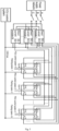
- the direct current modules and the power distribution units are respectively connected to a charge control unit, each power distribution unit is equipped with the same number of switch devices as the direct current modules, all the direct current modules are connectable to each of the power distribution units through the switch devices; each of the power distribution units corresponds to a parking space and is used as a charging source.
- PDU refers to a power distribution unit.
- CCU refers to a charge control unit.
- the direct current modules can be connected in parallel to any power distribution unit for outputting positive direct current voltages by switching corresponding switch devices on and off.
- Fig. 2 in the method, there are two or more direct current modules in a direct current module set and two or more power distribution unit, and the number of the switch devices of each PDU is equal to that of the direct current modules.
- the switch devices are switch relays
- each PDU further includes an AD sampling circuit and a micro control (MCU)
- the switch relays are switched on or off by the micro control (MCU)
- frontend voltages of the switch relays are sampled by the AD sampling circuit.
- the charge control unit comprises a micro control (MCU).
- MCU micro control
- the implementation procedure of the present disclosure is as follows: when the system is running, the CCU sends orders to the direct current modules, so as to order the direct current modules to output voltages with different specific values, and meanwhile, each PDU control system controls the sampling circuit to sample frontend voltages (outputted voltages of the direct current modules) of the switch relays; then, the CCU compares the sampled voltages of the switch relays with the specific voltages outputted by the direct current modules, so as to determine a corresponding relationship between the switch relays and the direct current modules.
- the PDU control system performs a logic computation according to an actual power demand of parking spaces and sends a control signal to switch on or off the multiple switch relays, thereby implementing a certain direct current module output combination and achieving a correctly output certain power.
- the power matching method for the matrix power distribution charging system specifically includes the following steps.
- the PDUs and the direct current modules respectively communicate with the CCU through a CAN bus
- the CCU, the PDUs, and the direct current modules respectively have a unique correspondence address ID, and have different address areas, for example, an address range of the CCU is 0-4, an address range of the PDUs is 5-20, an address range of the direct current modules is 21-50, and messages are sent to and received from each other through ID addresses.
- the CCU manages the whole running process of the system. Matching of the relays in the PDUs and the direct current modules is initiated by the CCU.
- the CCU sends orders to the direct current modules through the CAN bus, and the orders indicate specific voltages to be outputted.
- a voltage to be outputted by a module 1 is 40 V
- a voltage to be outputted by a module 2 is 80 V
- a voltage to be outputted by a module 3 is 60 V.
- a sampled voltage of a switch relay S-1 in a PDU-1 is 60 V
- the PDU-1 corresponds to the module 3
- sampled front-end voltages of a switch relay S-1 in a PDU-2 and a switch relay S-1 in a PDU-3 are 0 V.
- a sampled voltage of a switch relay S-2 in the PDU-2 is 40 V
- the PDU-2 corresponds to the module 1
- sampled front-end voltages of a switch relay S-2 in the PDU-1 and a switch relay S-2 in the PDU-3 are 0 V.
- a sampled voltage of a switch relay S-3 in the PDU-3 is 80 V
- the PDU-3 corresponds to the module 2
- sampled front-end voltages of a switch relay S-3 in the PDU-1 and a switch relay S-3 in the PDU-2 are 0 V.
- the module 1 corresponds to the switch relay S-2 in the PDU-2.
- the module 2 corresponds to the switch relay S-3 in the PDU-3.
- the module 3 corresponds to the switch relay S-1 in the PDU-1.
- a corresponding mapping relationship is established.
- the CCU achieves correct charging by controlling states of the switch relays in the PDUs and controlling module output combinations.
Landscapes
- Engineering & Computer Science (AREA)
- Power Engineering (AREA)
- Transportation (AREA)
- Mechanical Engineering (AREA)
- Charge And Discharge Circuits For Batteries Or The Like (AREA)
- Electric Propulsion And Braking For Vehicles (AREA)
- Direct Current Feeding And Distribution (AREA)
Claims (5)
- Leistungsanpassungsverfahren für ein Matrix-Leistungsverteilungs-Ladesystem, wobei das Matrix-Leistungsverteilungs-Ladesystem mindestens zwei Gleichstrommodule und eine Vielzahl von Leistungsverteilungseinheiten (PDUs) umfasst, wobei die Gleichstrommodule und die Leistungsverteilungseinheiten (PDUs) jeweils mit einer Ladesteuereinheit (CCU) verbunden sind; jede der Leistungsverteilungseinheiten (PDUs) umfasst Schaltvorrichtungen, deren Anzahl gleich der Anzahl der Gleichstrommodule ist, und jedes der Gleichstrommodule kann über eine der Schaltvorrichtungen mit jeder der Leistungsverteilungseinheiten verbunden werden; jede der Leistungsverteilungseinheiten entspricht einem Parkstellplatz und wird als Ladequelle verwendet;
wobei das Leistungsanpassungsverfahren die folgenden Schritte umfasst: Senden von Befehlen an die Gleichstrommodule durch die Ladesteuereinheit (CCU) nach der Inbetriebnahme des Matrix-Leistungsverteilungs-Ladesystems, um die Gleichstrommodule anzuweisen, Spannungen mit unterschiedlichen spezifischen Werten auszugeben; in der Zwischenzeit Abtasten der Spannungen an dem Anschluss, der direkt mit den Gleichstrommodulen jeder der Schaltvorrichtungen verbunden ist, durch die Leistungsverteilungseinheiten (PDUs) mittels einer Abtastschaltung und Senden der abgetasteten Spannungen an die Ladesteuereinheit (CCU) durch die Leistungsverteilungseinheiten (PDUs); und Vergleichen der empfangenen abgetasteten Spannungen mit den von jedem der Gleichstrommodule ausgegebenen Spannungen zum Bestimmen einer entsprechenden Beziehung zwischen jeder der Schaltvorrichtungen und jedem der Gleichstrommodule; schließlich logisches Berechnen durch die Ladesteuereinheit (CCU) gemäß den tatsächlichen Leistungsanforderungen der Parkstellplätze, um Steuerbefehle an die Leistungsverteilungseinheiten (PDUs) zu senden, und Ein- oder Ausschalten jeder der Schaltvorrichtungen durch die Leistungsverteilungseinheiten (PDUs) gemäß den empfangenen Steuerbefehlen, um eine Verbindung mit einer bestimmten Gleichstrommodul-Kombination herzustellen, um eine bestimmte Leistung korrekt auszugeben. - Leistungsanpassungsverfahren für ein Matrix-Leistungsverteilungs-Ladesystem, wobei das Matrix-Leistungsverteilungs-Ladesystem mindestens zwei Gleichstrommodule und eine Vielzahl von Leistungsverteilungseinheiten (PDUs) umfasst, wobei die Gleichstrommodule und die Leistungsverteilungseinheiten (PDUs) jeweils mit einer Ladesteuereinheit verbunden sind; jede der Leistungsverteilungseinheiten (PDUs) umfasst Schaltvorrichtungen, deren Anzahl gleich der Anzahl der Gleichstrommodule ist, und jedes der Gleichstrommodule kann über eine der Schaltvorrichtungen mit jeder der Leistungsverteilungseinheiten (PDUs) verbunden werden; jede der Leistungsverteilungseinheiten (PDUs) entspricht einem Parkstellplatz und wird als Ladequelle verwendet;
wobei das Leistungsanpassungsverfahren die folgenden Schritte umfasst:(1) Senden eines Zustandsbefehls durch die Ladesteuereinheit (CCU), der anzeigt, dass die Schaltvorrichtungen beginnen, sich mit den Gleichstrommodulen zu verbinden;(2) Senden von Nachrichten an jedes der Gleichstrommodule, eines nach dem anderen, durch die Ladesteuereinheit (CCU), um die Gleichstrommodule anzuweisen, Spannungen mit spezifischen Werten auszugeben; in der Zwischenzeit Empfangen der Nachrichten durch die Leistungsverteilungseinheiten (PDUs), um die spezifischen Werte der von den Gleichstrommodulen auszugebenden Spannungen zu erfahren;(3) jeweils Ausgabe der Spannungen mit bestimmten Werten durch die Gleichstrommodule gemäß den von der Ladesteuereinheit gesendeten Nachrichten;(4) Abtasten der Spannungen an dem Anschluss, der direkt mit den Gleichstrommodulen jeder der Schaltvorrichtungen verbunden ist, durch die Leistungsverteilungseinheiten (PDUs) mittels der Abtastschaltung, Vergleichen der abgetasteten Werte der Spannungen mit den Werten der Spannungen, die von den Gleichstrommodulen ausgegeben werden, um herauszufinden, welche Schaltvorrichtung und welches Gleichstrommodul einen ähnlichen Wert haben, und Herstellen einer eins-zu-eins-Beziehung;(5) Senden einer Abgleichs-Erfolgsmeldung an die Ladesteuereinheit (CCU) durch jede der Leistungsverteilungseinheiten (PDUs), wenn der Abgleich erfolgreich ist, nachdem die entsprechende Beziehung zwischen den Schaltvorrichtungen und den Gleichstrommodulen hergestellt wurde; oder Senden einer Abgleichs-Fehlermeldung an die Ladesteuereinheit (CCU), wenn der Abgleich fehlschlägt;(6) Senden eines "Abgleich vollständig"-Zustands an das Matrix-Leistungsverteilungs-Ladesystem, wenn die Ladesteuereinheit (CCU) alle Abgleichs-Meldungen der Leistungsverteilungseinheiten (PDUs) empfängt, und logisches Berechnen durch die Ladesteuereinheit (CCU) entsprechend der tatsächlichen Leistungsanforderungen der Parkstellplätze, um Steuerbefehle an die Leistungsverteilungseinheiten (PDUs) zu senden, und Ein- oder Ausschalten jeder der Schaltvorrichtungen durch die Leistungsverteilungseinheiten (PDUs) entsprechend den empfangenen Steuerbefehlen, um eine Verbindung mit einer bestimmten Gleichstrommodul-Kombination herzustellen, um eine bestimmte Leistung korrekt auszugeben. - Leistungsanpassungsverfahren nach Anspruch 1 oder 2, wobei die Schaltvorrichtungen Schaltrelais sind; jede der Leistungsverteilungseinheiten (PDUs) umfasst ferner eine analog-digital-Abtastschaltung und eine Mikrocontroller-Einheit; die Schaltrelais werden durch die Mikrocontroller-Einheit ein- oder ausgeschaltet, und Spannungen an dem Anschluss, der direkt mit den Gleichstrommodulen jedes der Schaltrelais verbunden ist, werden durch die analog-digital-Abtastschaltung abgetastet.
- Leistungsanpassungsverfahren nach Anspruch 1 oder 2, wobei die Gleichstrommodule und die Leistungsverteilungseinheiten (PDUs) jeweils über einen Controller Area Network Bus mit der Ladesteuereinheit (CCU) verbunden sind und darüber kommunizieren.
- Leistungsanpassungsverfahren nach Anspruch 1, wobei die Ladesteuereinheit (CCU) eine Mikrocontroller-Einheit umfasst.
Applications Claiming Priority (2)
| Application Number | Priority Date | Filing Date | Title |
|---|---|---|---|
| CN201510551423.7A CN105375552B (zh) | 2015-09-01 | 2015-09-01 | 一种矩阵式功率分配充电系统的功率匹配方法 |
| PCT/CN2016/096809 WO2017036349A1 (zh) | 2015-09-01 | 2016-08-26 | 一种矩阵式功率分配充电系统的功率匹配方法 |
Publications (4)
| Publication Number | Publication Date |
|---|---|
| EP3346571A1 EP3346571A1 (de) | 2018-07-11 |
| EP3346571A4 EP3346571A4 (de) | 2019-08-14 |
| EP3346571C0 EP3346571C0 (de) | 2023-12-27 |
| EP3346571B1 true EP3346571B1 (de) | 2023-12-27 |
Family
ID=55377464
Family Applications (1)
| Application Number | Title | Priority Date | Filing Date |
|---|---|---|---|
| EP16840778.1A Active EP3346571B1 (de) | 2015-09-01 | 2016-08-26 | Leistungsanpassungsverfahren eines ladesystems mit matrixleistungsverteilung |
Country Status (4)
| Country | Link |
|---|---|
| US (1) | US10447057B2 (de) |
| EP (1) | EP3346571B1 (de) |
| CN (1) | CN105375552B (de) |
| WO (1) | WO2017036349A1 (de) |
Families Citing this family (40)
| Publication number | Priority date | Publication date | Assignee | Title |
|---|---|---|---|---|
| CN105375552B (zh) * | 2015-09-01 | 2017-03-15 | 西安特锐德智能充电科技有限公司 | 一种矩阵式功率分配充电系统的功率匹配方法 |
| CN106711991A (zh) * | 2016-12-23 | 2017-05-24 | 长园深瑞继保自动化有限公司 | 可自由分配功率的电源模块及分配方法 |
| CN108242828A (zh) * | 2016-12-27 | 2018-07-03 | 飞宏科技股份有限公司 | 用于充电桩之智能功率分配系统 |
| CN107323274B (zh) * | 2017-02-14 | 2020-01-24 | 宁波三星智能电气有限公司 | 一种基于物联网的充电桩系统及其控制方法 |
| CN107117049B (zh) * | 2017-04-28 | 2019-12-13 | 西安特锐德智能充电科技有限公司 | 一种自识别模块位置的单桩多枪通道匹配方法 |
| CN110015021B (zh) * | 2017-09-14 | 2021-01-08 | 深圳智链物联科技有限公司 | 一种用于电动车的充电插座及充电系统 |
| CN108312871B (zh) * | 2018-02-02 | 2021-11-16 | 西安特锐德智能充电科技有限公司 | 一种控制功率模块组电流输出方法及系统 |
| CN108279621B (zh) * | 2018-04-11 | 2024-07-02 | 山东省科学院能源研究所 | 一种中频炉智能隔离型功率分配系统及方法 |
| CN108879903A (zh) * | 2018-08-10 | 2018-11-23 | 北京智充科技有限公司 | 一种多枪头直流充电桩系统及其充电功率分配方法 |
| CN109455106B (zh) * | 2018-10-17 | 2022-07-26 | 国网浙江省电力有限公司杭州供电公司 | 一种电动汽车智能充电站 |
| CN109591644A (zh) * | 2018-11-12 | 2019-04-09 | 江苏万帮德和新能源科技股份有限公司 | 直流充电堆动态智能功率分配系统及其分配方法 |
| CN109733230A (zh) * | 2018-12-21 | 2019-05-10 | 广西科技大学 | 一桩带多枪的电动汽车慢充及其管理系统 |
| KR102747491B1 (ko) * | 2019-10-17 | 2024-12-31 | 삼성전자주식회사 | 공진형 충전 회로를 포함하는 전자 장치 |
| EP4018526B1 (de) | 2019-10-17 | 2025-01-01 | Samsung Electronics Co., Ltd. | Elektronische vorrichtung, die eine resonanzladeschaltung einschliesst |
| WO2021075914A1 (en) | 2019-10-17 | 2021-04-22 | Samsung Electronics Co., Ltd. | Electronic device including resonant charging circuit |
| CN112776633B (zh) * | 2019-11-07 | 2022-05-17 | 国创移动能源创新中心(江苏)有限公司 | 一种采用移动式功率分配单元的充电系统及方法 |
| CN112238780A (zh) * | 2019-11-27 | 2021-01-19 | 北京新能源汽车技术创新中心有限公司 | 充电方法、系统及车辆 |
| CN111055717B (zh) * | 2019-12-30 | 2021-11-05 | 重庆国翰能源发展有限公司 | 一种基于电动汽车大功率柔性分配群充系统 |
| US11424621B2 (en) | 2020-01-28 | 2022-08-23 | Qualcomm Incorporated | Configurable redundant systems for safety critical applications |
| US12528379B2 (en) | 2020-04-16 | 2026-01-20 | Chargepoly | System and method for charging motor vehicles |
| FR3109339A1 (fr) * | 2020-04-16 | 2021-10-22 | Chargepoly | Systeme et procede de charge de vehicules automobiles |
| CN111301211A (zh) * | 2020-04-17 | 2020-06-19 | 河海大学常州校区 | 基于柔性充电功率共享超级充电桩 |
| CN111422084B (zh) * | 2020-04-27 | 2025-05-30 | 特瓦特能源科技有限公司 | 一种分级母线式柔性充电系统 |
| EP4173108A1 (de) * | 2020-06-30 | 2023-05-03 | I-Charging, Mobilidade Electrica, S.A. | Intelligentes ladesystem für batterien eines elektrofahrzeugs in gleichstrom |
| CN111959333B (zh) * | 2020-07-28 | 2021-08-27 | 福建星云电子股份有限公司 | 一种应用于充电桩的功率分配方法、设备及介质 |
| CN112224081A (zh) | 2020-10-15 | 2021-01-15 | 阳光电源股份有限公司 | 一种多枪的充电桩及充电桩电路 |
| CN112319298B (zh) * | 2020-11-04 | 2022-07-15 | 四川光慧新能源科技有限公司 | 一种多个充电模块协调电流分配的方法 |
| DE102020214260A1 (de) | 2020-11-12 | 2022-05-12 | Siemens Aktiengesellschaft | Betriebsverfahren für eine Ladevorrichtung und Ladevorrichtung |
| CN113022338A (zh) * | 2021-03-15 | 2021-06-25 | 西安特锐德智能充电科技有限公司 | 一种直流充电系统 |
| CN116601042B (zh) * | 2021-04-02 | 2025-09-23 | 浙江吉利控股集团有限公司 | 一种用于功率分配的配置方法、系统、设备及存储介质 |
| CN113147477A (zh) * | 2021-05-11 | 2021-07-23 | 万帮数字能源股份有限公司 | 一种用于大功率直流充电机功率分配单元的管理系统 |
| CN113183807A (zh) * | 2021-06-11 | 2021-07-30 | 杭州创睿新能源科技有限公司 | 一种模块化的新型充电桩设计 |
| CN113555926A (zh) * | 2021-07-14 | 2021-10-26 | 福建星云电子股份有限公司 | 一种多路充电dc柜及控制方法 |
| DE102022201140A1 (de) | 2022-02-03 | 2023-08-03 | Volkswagen Aktiengesellschaft | Gleichstrom-Ladestation, Verfahren zum Betreiben einer Gleichstrom-Ladestation und Wechselstrom-Ladestation |
| CN115276191B (zh) * | 2022-09-26 | 2023-01-03 | 西安特来电智能充电科技有限公司 | 一种功率分配方法、装置、设备及介质 |
| CN115923565B (zh) * | 2022-12-30 | 2025-02-14 | 领充新能源科技有限公司 | 功率模块控制方法、装置及系统 |
| EP4690418A1 (de) * | 2023-05-26 | 2026-02-11 | Siemens Aktiengesellschaft | Ladeanordnung für mehrere fahrzeuge |
| FR3165214A1 (fr) | 2024-07-31 | 2026-02-06 | Chargepoly | Systeme et procede de charge de vehicules automobiles |
| CN118991509B (zh) * | 2024-08-23 | 2025-10-28 | 深圳市道通合创数字能源有限公司 | 功率分配控制方法、充电主机、充电设备及芯片 |
| CN119773569B (zh) * | 2025-01-23 | 2025-10-14 | 江西瑞华智能科技有限公司 | 一种矩阵分体式直流充电堆及其功率分配方法 |
Family Cites Families (15)
| Publication number | Priority date | Publication date | Assignee | Title |
|---|---|---|---|---|
| US6081205A (en) * | 1992-05-19 | 2000-06-27 | Williams; Douglas J. | Electronic parking meter and electric automobile recharging station |
| JP2008199752A (ja) * | 2007-02-09 | 2008-08-28 | Kyushu Electric Power Co Inc | 充電装置 |
| CN201374569Y (zh) * | 2008-12-09 | 2009-12-30 | 剩沅科技股份有限公司 | 充电站 |
| KR101009485B1 (ko) * | 2010-04-20 | 2011-01-19 | (주)모던텍 | 유니버셜 충전 장치 |
| JP5647057B2 (ja) * | 2010-05-19 | 2014-12-24 | 株式会社日立製作所 | 充電装置、充電制御ユニット及び充電制御方法 |
| KR101585117B1 (ko) * | 2011-12-08 | 2016-01-21 | 가부시키가이샤 에네르기 오요 기쥬츠켄큐쇼 | 급속충전용 전원 시스템 |
| US9290103B2 (en) * | 2012-02-08 | 2016-03-22 | Control Module, Inc. | EVSE controller system |
| DE102012007158A1 (de) * | 2012-04-07 | 2013-10-10 | Daimler Ag | Pulswechselrichter mit Stromzwischenkreis zum Fahren und Laden eines batteriebetriebenen Elektrofahrzeugs |
| JP5680769B2 (ja) * | 2012-07-13 | 2015-03-04 | パナソニックIpマネジメント株式会社 | 蓄電池システム及びその制御方法 |
| CN103956894B (zh) * | 2014-04-17 | 2017-03-29 | 南京航空航天大学 | 一种基于三端口变换器的直流分布式供电系统及其控制方法 |
| CN204538735U (zh) * | 2015-03-20 | 2015-08-05 | 深圳奥特迅电力设备股份有限公司 | 矩阵式柔性充电堆 |
| CN105375552B (zh) * | 2015-09-01 | 2017-03-15 | 西安特锐德智能充电科技有限公司 | 一种矩阵式功率分配充电系统的功率匹配方法 |
| US10065519B1 (en) * | 2015-09-30 | 2018-09-04 | Evercharge, Inc. | Location power monitoring and charge distribution using intelligent electric vehicle supply equipment |
| WO2017147612A1 (en) * | 2016-02-25 | 2017-08-31 | California Institute Of Technology | Adaptive charging network using adaptive charging stations for electric vehicles |
| US10150380B2 (en) * | 2016-03-23 | 2018-12-11 | Chargepoint, Inc. | Dynamic allocation of power modules for charging electric vehicles |
-
2015
- 2015-09-01 CN CN201510551423.7A patent/CN105375552B/zh active Active
-
2016
- 2016-08-26 EP EP16840778.1A patent/EP3346571B1/de active Active
- 2016-08-26 US US15/741,291 patent/US10447057B2/en active Active
- 2016-08-26 WO PCT/CN2016/096809 patent/WO2017036349A1/zh not_active Ceased
Also Published As
| Publication number | Publication date |
|---|---|
| EP3346571A1 (de) | 2018-07-11 |
| WO2017036349A1 (zh) | 2017-03-09 |
| EP3346571C0 (de) | 2023-12-27 |
| CN105375552A (zh) | 2016-03-02 |
| EP3346571A4 (de) | 2019-08-14 |
| US20180205235A1 (en) | 2018-07-19 |
| CN105375552B (zh) | 2017-03-15 |
| US10447057B2 (en) | 2019-10-15 |
Similar Documents
| Publication | Publication Date | Title |
|---|---|---|
| EP3346571B1 (de) | Leistungsanpassungsverfahren eines ladesystems mit matrixleistungsverteilung | |
| CN103162372B (zh) | 空调器及其rs485总线系统以及总线系统控制方法 | |
| CN107901773A (zh) | 一种可调分体式直流充电系统及其控制方法 | |
| US20200373761A1 (en) | Photovoltaic power optimization system | |
| CN102183953A (zh) | 汽车电机控制器测试台 | |
| CN114336804B (zh) | 一种退役电池包的储能系统、方法和装置 | |
| CN201965213U (zh) | 电动汽车用动力电池电压巡检控制器 | |
| CN206698009U (zh) | 一种节能可靠双电源的直流屏柜系统 | |
| CN106712228A (zh) | 一种电动汽车充电桩控制系统 | |
| CN205335935U (zh) | 一种适应分布式充电系统的电动汽车充电机模块及充电机 | |
| CN107117049A (zh) | 一种自识别模块位置的单桩多枪通道匹配方法 | |
| CN207074880U (zh) | 一种低待机功耗的充电模块 | |
| CN202120048U (zh) | 仿真控制器以及包括其的车载模块运行环境仿真系统 | |
| CN108226848A (zh) | 一种电能表纠错系统及方法 | |
| CN218387308U (zh) | 用于站间安全信息传输系统的全自动脉冲产生和显示电路 | |
| CN105406568A (zh) | 高低频互补高效节能充电机 | |
| CN214647657U (zh) | 一种智能充电桩控制装置 | |
| CN205583809U (zh) | 直流系统充电回路 | |
| CN104898064A (zh) | 一种飞渡电容的采样电路及采样方法 | |
| CN212518532U (zh) | 一种nb-iot市电油机自动切换设备 | |
| CN205248847U (zh) | 一种大容量储能系统蓄电池充放电装置 | |
| CN104977546B (zh) | 一种面向变电站的二次直流电源丢失判别方法 | |
| CN211266498U (zh) | 连接控制装置及供电系统 | |
| CN208781392U (zh) | 一种模块化数据采集器 | |
| CN208782504U (zh) | 一种基于物联网控制的智能孤岛电站 |
Legal Events
| Date | Code | Title | Description |
|---|---|---|---|
| STAA | Information on the status of an ep patent application or granted ep patent |
Free format text: STATUS: THE INTERNATIONAL PUBLICATION HAS BEEN MADE |
|
| PUAI | Public reference made under article 153(3) epc to a published international application that has entered the european phase |
Free format text: ORIGINAL CODE: 0009012 |
|
| STAA | Information on the status of an ep patent application or granted ep patent |
Free format text: STATUS: REQUEST FOR EXAMINATION WAS MADE |
|
| 17P | Request for examination filed |
Effective date: 20171220 |
|
| AK | Designated contracting states |
Kind code of ref document: A1 Designated state(s): AL AT BE BG CH CY CZ DE DK EE ES FI FR GB GR HR HU IE IS IT LI LT LU LV MC MK MT NL NO PL PT RO RS SE SI SK SM TR |
|
| AX | Request for extension of the european patent |
Extension state: BA ME |
|
| DAV | Request for validation of the european patent (deleted) | ||
| DAX | Request for extension of the european patent (deleted) | ||
| A4 | Supplementary search report drawn up and despatched |
Effective date: 20190716 |
|
| RIC1 | Information provided on ipc code assigned before grant |
Ipc: B60L 53/30 20190101ALI20190710BHEP Ipc: B60L 53/67 20190101ALI20190710BHEP Ipc: H02J 7/00 20060101AFI20190710BHEP Ipc: B60L 53/62 20190101ALI20190710BHEP Ipc: B60L 53/10 20190101ALI20190710BHEP |
|
| STAA | Information on the status of an ep patent application or granted ep patent |
Free format text: STATUS: EXAMINATION IS IN PROGRESS |
|
| 17Q | First examination report despatched |
Effective date: 20210719 |
|
| REG | Reference to a national code |
Ref country code: DE Ref legal event code: R079 Ref document number: 602016085035 Country of ref document: DE Free format text: PREVIOUS MAIN CLASS: H02J0007000000 Ipc: B60L0053670000 |
|
| RIC1 | Information provided on ipc code assigned before grant |
Ipc: B60L 53/30 20190101ALI20230501BHEP Ipc: B60L 53/10 20190101ALI20230501BHEP Ipc: B60L 53/62 20190101ALI20230501BHEP Ipc: H02J 7/00 20060101ALI20230501BHEP Ipc: B60L 53/60 20190101ALI20230501BHEP Ipc: B60L 53/67 20190101AFI20230501BHEP |
|
| GRAP | Despatch of communication of intention to grant a patent |
Free format text: ORIGINAL CODE: EPIDOSNIGR1 |
|
| STAA | Information on the status of an ep patent application or granted ep patent |
Free format text: STATUS: GRANT OF PATENT IS INTENDED |
|
| INTG | Intention to grant announced |
Effective date: 20230626 |
|
| GRAS | Grant fee paid |
Free format text: ORIGINAL CODE: EPIDOSNIGR3 |
|
| GRAA | (expected) grant |
Free format text: ORIGINAL CODE: 0009210 |
|
| STAA | Information on the status of an ep patent application or granted ep patent |
Free format text: STATUS: THE PATENT HAS BEEN GRANTED |
|
| AK | Designated contracting states |
Kind code of ref document: B1 Designated state(s): AL AT BE BG CH CY CZ DE DK EE ES FI FR GB GR HR HU IE IS IT LI LT LU LV MC MK MT NL NO PL PT RO RS SE SI SK SM TR |
|
| RAP3 | Party data changed (applicant data changed or rights of an application transferred) |
Owner name: XI'AN TELD INTELLIGENT CHARGING TECHNOLOGY CO., LTD. |
|
| REG | Reference to a national code |
Ref country code: GB Ref legal event code: FG4D |
|
| REG | Reference to a national code |
Ref country code: CH Ref legal event code: EP |
|
| REG | Reference to a national code |
Ref country code: DE Ref legal event code: R096 Ref document number: 602016085035 Country of ref document: DE |
|
| REG | Reference to a national code |
Ref country code: IE Ref legal event code: FG4D |
|
| U01 | Request for unitary effect filed |
Effective date: 20240125 |
|
| U07 | Unitary effect registered |
Designated state(s): AT BE BG DE DK EE FI FR IT LT LU LV MT NL PT SE SI Effective date: 20240202 |
|
| PG25 | Lapsed in a contracting state [announced via postgrant information from national office to epo] |
Ref country code: GR Free format text: LAPSE BECAUSE OF FAILURE TO SUBMIT A TRANSLATION OF THE DESCRIPTION OR TO PAY THE FEE WITHIN THE PRESCRIBED TIME-LIMIT Effective date: 20240328 |
|
| PG25 | Lapsed in a contracting state [announced via postgrant information from national office to epo] |
Ref country code: ES Free format text: LAPSE BECAUSE OF FAILURE TO SUBMIT A TRANSLATION OF THE DESCRIPTION OR TO PAY THE FEE WITHIN THE PRESCRIBED TIME-LIMIT Effective date: 20231227 |
|
| PG25 | Lapsed in a contracting state [announced via postgrant information from national office to epo] |
Ref country code: GR Free format text: LAPSE BECAUSE OF FAILURE TO SUBMIT A TRANSLATION OF THE DESCRIPTION OR TO PAY THE FEE WITHIN THE PRESCRIBED TIME-LIMIT Effective date: 20240328 Ref country code: ES Free format text: LAPSE BECAUSE OF FAILURE TO SUBMIT A TRANSLATION OF THE DESCRIPTION OR TO PAY THE FEE WITHIN THE PRESCRIBED TIME-LIMIT Effective date: 20231227 |
|
| PG25 | Lapsed in a contracting state [announced via postgrant information from national office to epo] |
Ref country code: RS Free format text: LAPSE BECAUSE OF FAILURE TO SUBMIT A TRANSLATION OF THE DESCRIPTION OR TO PAY THE FEE WITHIN THE PRESCRIBED TIME-LIMIT Effective date: 20231227 Ref country code: NO Free format text: LAPSE BECAUSE OF FAILURE TO SUBMIT A TRANSLATION OF THE DESCRIPTION OR TO PAY THE FEE WITHIN THE PRESCRIBED TIME-LIMIT Effective date: 20240327 Ref country code: HR Free format text: LAPSE BECAUSE OF FAILURE TO SUBMIT A TRANSLATION OF THE DESCRIPTION OR TO PAY THE FEE WITHIN THE PRESCRIBED TIME-LIMIT Effective date: 20231227 |
|
| PG25 | Lapsed in a contracting state [announced via postgrant information from national office to epo] |
Ref country code: IS Free format text: LAPSE BECAUSE OF FAILURE TO SUBMIT A TRANSLATION OF THE DESCRIPTION OR TO PAY THE FEE WITHIN THE PRESCRIBED TIME-LIMIT Effective date: 20240427 |
|
| PG25 | Lapsed in a contracting state [announced via postgrant information from national office to epo] |
Ref country code: CZ Free format text: LAPSE BECAUSE OF FAILURE TO SUBMIT A TRANSLATION OF THE DESCRIPTION OR TO PAY THE FEE WITHIN THE PRESCRIBED TIME-LIMIT Effective date: 20231227 |
|
| PG25 | Lapsed in a contracting state [announced via postgrant information from national office to epo] |
Ref country code: SK Free format text: LAPSE BECAUSE OF FAILURE TO SUBMIT A TRANSLATION OF THE DESCRIPTION OR TO PAY THE FEE WITHIN THE PRESCRIBED TIME-LIMIT Effective date: 20231227 |
|
| PG25 | Lapsed in a contracting state [announced via postgrant information from national office to epo] |
Ref country code: SM Free format text: LAPSE BECAUSE OF FAILURE TO SUBMIT A TRANSLATION OF THE DESCRIPTION OR TO PAY THE FEE WITHIN THE PRESCRIBED TIME-LIMIT Effective date: 20231227 Ref country code: SK Free format text: LAPSE BECAUSE OF FAILURE TO SUBMIT A TRANSLATION OF THE DESCRIPTION OR TO PAY THE FEE WITHIN THE PRESCRIBED TIME-LIMIT Effective date: 20231227 Ref country code: RO Free format text: LAPSE BECAUSE OF FAILURE TO SUBMIT A TRANSLATION OF THE DESCRIPTION OR TO PAY THE FEE WITHIN THE PRESCRIBED TIME-LIMIT Effective date: 20231227 Ref country code: IS Free format text: LAPSE BECAUSE OF FAILURE TO SUBMIT A TRANSLATION OF THE DESCRIPTION OR TO PAY THE FEE WITHIN THE PRESCRIBED TIME-LIMIT Effective date: 20240427 Ref country code: CZ Free format text: LAPSE BECAUSE OF FAILURE TO SUBMIT A TRANSLATION OF THE DESCRIPTION OR TO PAY THE FEE WITHIN THE PRESCRIBED TIME-LIMIT Effective date: 20231227 |
|
| PG25 | Lapsed in a contracting state [announced via postgrant information from national office to epo] |
Ref country code: PL Free format text: LAPSE BECAUSE OF FAILURE TO SUBMIT A TRANSLATION OF THE DESCRIPTION OR TO PAY THE FEE WITHIN THE PRESCRIBED TIME-LIMIT Effective date: 20231227 |
|
| PG25 | Lapsed in a contracting state [announced via postgrant information from national office to epo] |
Ref country code: PL Free format text: LAPSE BECAUSE OF FAILURE TO SUBMIT A TRANSLATION OF THE DESCRIPTION OR TO PAY THE FEE WITHIN THE PRESCRIBED TIME-LIMIT Effective date: 20231227 |
|
| U20 | Renewal fee for the european patent with unitary effect paid |
Year of fee payment: 9 Effective date: 20240726 |
|
| REG | Reference to a national code |
Ref country code: DE Ref legal event code: R097 Ref document number: 602016085035 Country of ref document: DE |
|
| U1N | Appointed representative for the unitary patent procedure changed after the registration of the unitary effect |
Representative=s name: KARO IP; DE |
|
| PLBE | No opposition filed within time limit |
Free format text: ORIGINAL CODE: 0009261 |
|
| STAA | Information on the status of an ep patent application or granted ep patent |
Free format text: STATUS: NO OPPOSITION FILED WITHIN TIME LIMIT |
|
| 26N | No opposition filed |
Effective date: 20240930 |
|
| REG | Reference to a national code |
Ref country code: CH Ref legal event code: PL |
|
| GBPC | Gb: european patent ceased through non-payment of renewal fee |
Effective date: 20240826 |
|
| PG25 | Lapsed in a contracting state [announced via postgrant information from national office to epo] |
Ref country code: MC Free format text: LAPSE BECAUSE OF FAILURE TO SUBMIT A TRANSLATION OF THE DESCRIPTION OR TO PAY THE FEE WITHIN THE PRESCRIBED TIME-LIMIT Effective date: 20231227 Ref country code: CH Free format text: LAPSE BECAUSE OF NON-PAYMENT OF DUE FEES Effective date: 20240831 |
|
| PG25 | Lapsed in a contracting state [announced via postgrant information from national office to epo] |
Ref country code: GB Free format text: LAPSE BECAUSE OF NON-PAYMENT OF DUE FEES Effective date: 20240826 |
|
| PG25 | Lapsed in a contracting state [announced via postgrant information from national office to epo] |
Ref country code: IE Free format text: LAPSE BECAUSE OF NON-PAYMENT OF DUE FEES Effective date: 20240826 |
|
| U20 | Renewal fee for the european patent with unitary effect paid |
Year of fee payment: 10 Effective date: 20250826 |
|
| PG25 | Lapsed in a contracting state [announced via postgrant information from national office to epo] |
Ref country code: CY Free format text: LAPSE BECAUSE OF FAILURE TO SUBMIT A TRANSLATION OF THE DESCRIPTION OR TO PAY THE FEE WITHIN THE PRESCRIBED TIME-LIMIT; INVALID AB INITIO Effective date: 20160826 |
|
| PG25 | Lapsed in a contracting state [announced via postgrant information from national office to epo] |
Ref country code: HU Free format text: LAPSE BECAUSE OF FAILURE TO SUBMIT A TRANSLATION OF THE DESCRIPTION OR TO PAY THE FEE WITHIN THE PRESCRIBED TIME-LIMIT; INVALID AB INITIO Effective date: 20160826 |