EP3346368B1 - Device, method and system for control of a target apparatus - Google Patents
Device, method and system for control of a target apparatus Download PDFInfo
- Publication number
- EP3346368B1 EP3346368B1 EP16841280.7A EP16841280A EP3346368B1 EP 3346368 B1 EP3346368 B1 EP 3346368B1 EP 16841280 A EP16841280 A EP 16841280A EP 3346368 B1 EP3346368 B1 EP 3346368B1
- Authority
- EP
- European Patent Office
- Prior art keywords
- neck
- line
- sight
- user
- motion
- Prior art date
- Legal status (The legal status is an assumption and is not a legal conclusion. Google has not performed a legal analysis and makes no representation as to the accuracy of the status listed.)
- Active
Links
- 238000000034 method Methods 0.000 title claims description 63
- 238000001514 detection method Methods 0.000 claims description 58
- 210000003128 head Anatomy 0.000 description 41
- 230000008569 process Effects 0.000 description 37
- 230000009471 action Effects 0.000 description 35
- 230000000007 visual effect Effects 0.000 description 23
- 238000010586 diagram Methods 0.000 description 16
- 238000012790 confirmation Methods 0.000 description 12
- 238000005286 illumination Methods 0.000 description 12
- 238000003384 imaging method Methods 0.000 description 11
- 238000012545 processing Methods 0.000 description 11
- 238000004891 communication Methods 0.000 description 9
- 210000001747 pupil Anatomy 0.000 description 6
- 238000001356 surgical procedure Methods 0.000 description 6
- 238000003780 insertion Methods 0.000 description 5
- 230000037431 insertion Effects 0.000 description 5
- 230000001133 acceleration Effects 0.000 description 4
- 230000003287 optical effect Effects 0.000 description 4
- XLYOFNOQVPJJNP-UHFFFAOYSA-N water Substances O XLYOFNOQVPJJNP-UHFFFAOYSA-N 0.000 description 4
- 208000003443 Unconsciousness Diseases 0.000 description 3
- 238000000605 extraction Methods 0.000 description 3
- 210000004237 neck muscle Anatomy 0.000 description 3
- 238000011282 treatment Methods 0.000 description 3
- 206010028980 Neoplasm Diseases 0.000 description 2
- 210000000988 bone and bone Anatomy 0.000 description 2
- 238000011156 evaluation Methods 0.000 description 2
- 230000007257 malfunction Effects 0.000 description 2
- 238000005452 bending Methods 0.000 description 1
- 210000004556 brain Anatomy 0.000 description 1
- 230000008859 change Effects 0.000 description 1
- 230000000295 complement effect Effects 0.000 description 1
- 230000000694 effects Effects 0.000 description 1
- 238000005516 engineering process Methods 0.000 description 1
- 230000001788 irregular Effects 0.000 description 1
- 239000004973 liquid crystal related substance Substances 0.000 description 1
- 229910044991 metal oxide Inorganic materials 0.000 description 1
- 150000004706 metal oxides Chemical class 0.000 description 1
- 210000003205 muscle Anatomy 0.000 description 1
- 230000003183 myoelectrical effect Effects 0.000 description 1
- 238000011328 necessary treatment Methods 0.000 description 1
- 230000004044 response Effects 0.000 description 1
- 239000004065 semiconductor Substances 0.000 description 1
- 238000005406 washing Methods 0.000 description 1
Images


Classifications
-
- G—PHYSICS
- G06—COMPUTING; CALCULATING OR COUNTING
- G06F—ELECTRIC DIGITAL DATA PROCESSING
- G06F3/00—Input arrangements for transferring data to be processed into a form capable of being handled by the computer; Output arrangements for transferring data from processing unit to output unit, e.g. interface arrangements
- G06F3/01—Input arrangements or combined input and output arrangements for interaction between user and computer
- G06F3/011—Arrangements for interaction with the human body, e.g. for user immersion in virtual reality
- G06F3/013—Eye tracking input arrangements
-
- A—HUMAN NECESSITIES
- A61—MEDICAL OR VETERINARY SCIENCE; HYGIENE
- A61B—DIAGNOSIS; SURGERY; IDENTIFICATION
- A61B1/00—Instruments for performing medical examinations of the interior of cavities or tubes of the body by visual or photographical inspection, e.g. endoscopes; Illuminating arrangements therefor
- A61B1/04—Instruments for performing medical examinations of the interior of cavities or tubes of the body by visual or photographical inspection, e.g. endoscopes; Illuminating arrangements therefor combined with photographic or television appliances
-
- A—HUMAN NECESSITIES
- A61—MEDICAL OR VETERINARY SCIENCE; HYGIENE
- A61B—DIAGNOSIS; SURGERY; IDENTIFICATION
- A61B5/00—Measuring for diagnostic purposes; Identification of persons
- A61B5/103—Detecting, measuring or recording devices for testing the shape, pattern, colour, size or movement of the body or parts thereof, for diagnostic purposes
- A61B5/11—Measuring movement of the entire body or parts thereof, e.g. head or hand tremor, mobility of a limb
- A61B5/1113—Local tracking of patients, e.g. in a hospital or private home
- A61B5/1114—Tracking parts of the body
-
- A—HUMAN NECESSITIES
- A61—MEDICAL OR VETERINARY SCIENCE; HYGIENE
- A61B—DIAGNOSIS; SURGERY; IDENTIFICATION
- A61B5/00—Measuring for diagnostic purposes; Identification of persons
- A61B5/103—Detecting, measuring or recording devices for testing the shape, pattern, colour, size or movement of the body or parts thereof, for diagnostic purposes
- A61B5/11—Measuring movement of the entire body or parts thereof, e.g. head or hand tremor, mobility of a limb
- A61B5/1126—Measuring movement of the entire body or parts thereof, e.g. head or hand tremor, mobility of a limb using a particular sensing technique
- A61B5/1128—Measuring movement of the entire body or parts thereof, e.g. head or hand tremor, mobility of a limb using a particular sensing technique using image analysis
-
- A—HUMAN NECESSITIES
- A61—MEDICAL OR VETERINARY SCIENCE; HYGIENE
- A61B—DIAGNOSIS; SURGERY; IDENTIFICATION
- A61B5/00—Measuring for diagnostic purposes; Identification of persons
- A61B5/68—Arrangements of detecting, measuring or recording means, e.g. sensors, in relation to patient
- A61B5/6801—Arrangements of detecting, measuring or recording means, e.g. sensors, in relation to patient specially adapted to be attached to or worn on the body surface
- A61B5/6813—Specially adapted to be attached to a specific body part
- A61B5/6822—Neck
-
- A—HUMAN NECESSITIES
- A61—MEDICAL OR VETERINARY SCIENCE; HYGIENE
- A61B—DIAGNOSIS; SURGERY; IDENTIFICATION
- A61B5/00—Measuring for diagnostic purposes; Identification of persons
- A61B5/74—Details of notification to user or communication with user or patient ; user input means
- A61B5/7475—User input or interface means, e.g. keyboard, pointing device, joystick
-
- G—PHYSICS
- G06—COMPUTING; CALCULATING OR COUNTING
- G06F—ELECTRIC DIGITAL DATA PROCESSING
- G06F3/00—Input arrangements for transferring data to be processed into a form capable of being handled by the computer; Output arrangements for transferring data from processing unit to output unit, e.g. interface arrangements
- G06F3/01—Input arrangements or combined input and output arrangements for interaction between user and computer
- G06F3/011—Arrangements for interaction with the human body, e.g. for user immersion in virtual reality
- G06F3/012—Head tracking input arrangements
-
- G—PHYSICS
- G06—COMPUTING; CALCULATING OR COUNTING
- G06F—ELECTRIC DIGITAL DATA PROCESSING
- G06F3/00—Input arrangements for transferring data to be processed into a form capable of being handled by the computer; Output arrangements for transferring data from processing unit to output unit, e.g. interface arrangements
- G06F3/01—Input arrangements or combined input and output arrangements for interaction between user and computer
- G06F3/011—Arrangements for interaction with the human body, e.g. for user immersion in virtual reality
- G06F3/015—Input arrangements based on nervous system activity detection, e.g. brain waves [EEG] detection, electromyograms [EMG] detection, electrodermal response detection
-
- G—PHYSICS
- G06—COMPUTING; CALCULATING OR COUNTING
- G06F—ELECTRIC DIGITAL DATA PROCESSING
- G06F3/00—Input arrangements for transferring data to be processed into a form capable of being handled by the computer; Output arrangements for transferring data from processing unit to output unit, e.g. interface arrangements
- G06F3/01—Input arrangements or combined input and output arrangements for interaction between user and computer
- G06F3/017—Gesture based interaction, e.g. based on a set of recognized hand gestures
-
- G—PHYSICS
- G06—COMPUTING; CALCULATING OR COUNTING
- G06F—ELECTRIC DIGITAL DATA PROCESSING
- G06F3/00—Input arrangements for transferring data to be processed into a form capable of being handled by the computer; Output arrangements for transferring data from processing unit to output unit, e.g. interface arrangements
- G06F3/01—Input arrangements or combined input and output arrangements for interaction between user and computer
- G06F3/03—Arrangements for converting the position or the displacement of a member into a coded form
- G06F3/033—Pointing devices displaced or positioned by the user, e.g. mice, trackballs, pens or joysticks; Accessories therefor
- G06F3/0346—Pointing devices displaced or positioned by the user, e.g. mice, trackballs, pens or joysticks; Accessories therefor with detection of the device orientation or free movement in a 3D space, e.g. 3D mice, 6-DOF [six degrees of freedom] pointers using gyroscopes, accelerometers or tilt-sensors
-
- G—PHYSICS
- G06—COMPUTING; CALCULATING OR COUNTING
- G06F—ELECTRIC DIGITAL DATA PROCESSING
- G06F3/00—Input arrangements for transferring data to be processed into a form capable of being handled by the computer; Output arrangements for transferring data from processing unit to output unit, e.g. interface arrangements
- G06F3/01—Input arrangements or combined input and output arrangements for interaction between user and computer
- G06F3/03—Arrangements for converting the position or the displacement of a member into a coded form
- G06F3/033—Pointing devices displaced or positioned by the user, e.g. mice, trackballs, pens or joysticks; Accessories therefor
- G06F3/038—Control and interface arrangements therefor, e.g. drivers or device-embedded control circuitry
-
- G—PHYSICS
- G06—COMPUTING; CALCULATING OR COUNTING
- G06F—ELECTRIC DIGITAL DATA PROCESSING
- G06F3/00—Input arrangements for transferring data to be processed into a form capable of being handled by the computer; Output arrangements for transferring data from processing unit to output unit, e.g. interface arrangements
- G06F3/16—Sound input; Sound output
-
- G—PHYSICS
- G10—MUSICAL INSTRUMENTS; ACOUSTICS
- G10L—SPEECH ANALYSIS OR SYNTHESIS; SPEECH RECOGNITION; SPEECH OR VOICE PROCESSING; SPEECH OR AUDIO CODING OR DECODING
- G10L15/00—Speech recognition
- G10L15/22—Procedures used during a speech recognition process, e.g. man-machine dialogue
-
- A—HUMAN NECESSITIES
- A61—MEDICAL OR VETERINARY SCIENCE; HYGIENE
- A61B—DIAGNOSIS; SURGERY; IDENTIFICATION
- A61B2560/00—Constructional details of operational features of apparatus; Accessories for medical measuring apparatus
- A61B2560/04—Constructional details of apparatus
- A61B2560/0487—Special user inputs or interfaces
-
- G—PHYSICS
- G06—COMPUTING; CALCULATING OR COUNTING
- G06V—IMAGE OR VIDEO RECOGNITION OR UNDERSTANDING
- G06V40/00—Recognition of biometric, human-related or animal-related patterns in image or video data
- G06V40/20—Movements or behaviour, e.g. gesture recognition
-
- G—PHYSICS
- G10—MUSICAL INSTRUMENTS; ACOUSTICS
- G10L—SPEECH ANALYSIS OR SYNTHESIS; SPEECH RECOGNITION; SPEECH OR VOICE PROCESSING; SPEECH OR AUDIO CODING OR DECODING
- G10L15/00—Speech recognition
- G10L15/22—Procedures used during a speech recognition process, e.g. man-machine dialogue
- G10L2015/223—Execution procedure of a spoken command
Definitions
- the present invention relates to an apparatus operation device including a line-of-sight detecting unit, a determining unit that determines at least a target apparatus based on a detected line of sight, and a control unit that controls the target apparatus. It also relates to an apparatus operation method, and an electronic apparatus system, and particularly relates to a technique for operating an apparatus by using a line of sight and a motion of the neck of a user. Apparatus of the above type is known from US2013/147686 .
- Various types of apparatuses are typically operated by a user with his/her hand or foot.
- restrictions may be imposed on a user's action or the arrangement of the apparatus or an operation device.
- a user may be unable to freely use both hands.
- the user may need to peel off/put on gloves or wash hands before/after operating the apparatus. That is, in operation techniques using a hand or foot, it may be difficult to smoothly perform an operation.
- operation techniques not using a hand or foot operation techniques using a line of sight and a gesture are known (see, for example, JP2014-126997A , JP2000-163196A , JP2001-100903A , and JP2007-195892A ).
- JP2014-126997A and JP2000-163196A describe that a point of gaze of a user is detected based on a captured image of the head of the user, a predetermined action of the head (for example, a nod action of shaking the head vertically) is detected based on the captured image of the head of the user, and an operation corresponding to the point of gaze of the user is decided on upon the predetermined action of the head being detected.
- a predetermined action of the head for example, a nod action of shaking the head vertically
- JP2001-100903A describes that an action of a hand of a user is detected based on a captured image of the hand of the user, and a process of moving a cursor to a line-of-sight position is started (turn on a cursor following mode) if one finger is raised, whereas the process of moving the cursor to the line-of-sight position is finished (turn off the cursor following mode) if no finger is raised but a fist is made.
- JP2007-195892A describes that a line-of-sight position is calculated based on an image captured by a camera of a unit that can be mounted on the head of a user (line-of-sight position input unit) and a focus position is moved to the line-of-sight position.
- JP2007-195892A also describes that a magnetic sensor for detecting a position and an angle of the head of the user is used.
- JP2001-299691A describes that, if a user presses a foot switch and inputs a name (for example, "decrease light intensity") of an icon (for example, a "decrease light intensity” icon) by voice while gazing at the icon displayed on a display unit for a predetermined period of time or more, the operation of the user is decided on and an action corresponding to the icon is performed.
- the voice input is performed by using a pin microphone that is attached to clothes or a head microphone that is mounted on the head.
- US 2014/300532 A shows an apparatus for controlling a near-eye-display. A collar at the user's neck detects movements of the user's head.
- an operation determined based on detection of a line of sight is decided on upon a predetermined action of the head of a user being detected, and thus the effect of avoiding a malfunction can be more expected than in the case of only performing determination based on detection of a line of sight.
- an action of the head of the user is recognized based on an image that is obtained by photographing the head, it is difficult for the apparatus to appropriately determine whether the motion of the head results from a motion of neck muscles according to the user's intention or results from an unconscious motion of the body.
- a determination process is modified to a determination process in which a small motion or a simple motion performed by a user is ignored by the apparatus and in which only a large motion (for example, a motion of tilting the head by 45 degrees or more) or a complicated motion performed by the user is regarded as effective, the user is forced to perform a large motion or a complicated motion. Accordingly, it is impossible to perform a smooth operation although a malfunction can be avoided. In addition, the user will get tired.
- JP2001-100903A JP2007-195892A , and JP2001-299691A . It is not possible to achieve both an easy operation under a situation where both hands of a user are occupied and appropriate detection and execution of an operation intended by the user.
- the present invention has been made in view of the above-described circumstances, and an object of the present invention is to provide an apparatus operation device, an apparatus operation method, and an electronic apparatus system that enable a user to easily perform an operation even if both hands are occupied and that enable an operation intended by the user to be appropriately detected and performed.
- an apparatus operation device includes the features of claim 1.
- an operation can be easily performed even if both hands of a user are occupied, and an operation intended by the user can be appropriately detected and performed.
- the determining unit determines, based on the line of sight that has been detected, at least one of the target apparatus or the operation details, and confirms the determination, based on the motion of the neck that has been detected.
- the line-of-sight detecting unit detects a movement of the line of sight
- the determining unit determines, based on the movement of the line of sight that has been detected, at least one of the target apparatus or the operation details.
- the operation details include a function that the control unit causes the target apparatus to execute, and an execution condition for the function.
- the apparatus operation device includes a voice recognizing unit that recognizes a voice of the user by using a vibration of a throat of the user, the vibration being detected by the neck-mounted terminal.
- the apparatus operation device includes a voice recording unit that records the voice that has been recognized.
- an apparatus operation method according to the present invention is an apparatus operation method defined by claim 7.
- an electronic apparatus system includes the apparatus operation device and an electronic apparatus which is the target apparatus.
- the electronic apparatus is a medical apparatus, for example.
- an operation can be easily performed even if both hands of a user are occupied, and an operation intended by the user can be appropriately detected and performed.
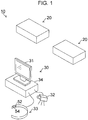
- Fig. 1 is a diagram illustrating the overall configuration of an example of an electronic apparatus system according to a first embodiment of the present invention
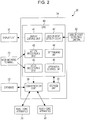
- Fig. 2 is a block diagram illustrating an example of an apparatus operation device according to the first embodiment of the present invention.
- an electronic apparatus system 10 includes electronic apparatuses 20, each of which is a target apparatus to be operated, and an apparatus operation device 30 that controls the electronic apparatuses 20.
- the apparatus operation device 30 includes a display unit 31 (also referred to as a "display”) that performs display for a user, a line-of-sight detecting camera 32 that captures an image of the face of the user to detect a line of sight of the user, a neck-mounted terminal 33 that is mounted around the neck of the user and detects a motion of the neck of the user, and an arithmetic unit 34 that serves as a main body unit, which controls the display unit 31, the line-of-sight detecting camera 32, and the neck-mounted terminal 33, and that performs various arithmetic operations.
- a display unit 31 also referred to as a "display”
- a line-of-sight detecting camera 32 that captures an image of the face of the user to detect a line of sight of the user
- a neck-mounted terminal 33 that is mounted around the neck of the user and detects a motion of the neck of the user
- an arithmetic unit 34 that serves as a main body unit, which
- the display unit 31 is constituted by a display device, such as a liquid crystal display device.
- the line-of-sight detecting camera 32 is located near the display unit 31, captures an image of at least an eye of the user to generate an image (hereinafter referred to as a "user image") including the image of the eye, and outputs the generated image.
- the extraction may be performed by using a function of the line-of-sight detecting camera 32, or a function of the extraction may be provided in the arithmetic unit 34.
- a plurality of line-of-sight detecting cameras 32 may be provided.
- the neck-mounted terminal 33 is a terminal that is to be mounted around the neck of the user and includes, as illustrated in Fig. 1 , a neck motion sensor 52 that detects a motion of the neck of the user and a vibration sensor 54 that detects a vibration of the throat of the user on the neck.
- a sensor device such as a myoelectric sensor that detects a motion of a neck muscle, a distortion sensor, or an acceleration sensor, is used.
- a sensor device other than these sensors may be used.
- a motion of the neck any of a motion of a neck muscle, a motion of a neck bone, or a motion of a neck surface (i.e., a motion of a neck skin) may be detected by the neck motion sensor 52.
- a plurality of types of sensor devices may be used to perform detection.
- the vibration sensor 54 an acceleration sensor that detects a vibration of a neck bone is used, for example. Another type of sensor may be used.
- a single sensor device may be implemented as the neck motion sensor 52 and the vibration sensor 54, and the single sensor device may be caused to detect a motion of the neck and a vibration of the throat.
- a single acceleration sensor is implemented as the neck motion sensor 52 and the vibration sensor 54, a low-frequency component is extracted from an output signal of the acceleration sensor to generate a signal representing a motion of the neck, and a high-frequency component is extracted from the output signal to generate a signal representing a vibration of the throat.
- the arithmetic unit 34 includes a communication unit 38 that communicates with the plurality of electronic apparatuses 20, a storage unit 39 that stores a program for controlling the operation of the electronic apparatuses 20 and information that is necessary to execute the program, and a central processing unit (CPU) 40 that controls the individual units of the apparatus operation device 30 by executing the program stored in the storage unit 39.
- a communication unit 38 that communicates with the plurality of electronic apparatuses 20
- a storage unit 39 that stores a program for controlling the operation of the electronic apparatuses 20 and information that is necessary to execute the program
- CPU central processing unit
- the communication unit 38 is constituted by a communication device that communicates with the electronic apparatuses 20.
- Fig. 1 illustrates a case where the communication unit 38 communicates with the electronic apparatuses 20 in a wireless manner, but the communication unit 38 may communicate with the electronic apparatuses 20 in a wired manner through a local area network or the like.
- the communication unit 38 may communicate with a device outside the arithmetic unit 34 (for example, a database 22), which is not illustrated in Fig. 1 , through a local area network or the like.
- the storage unit 39 includes a nonvolatile storage device that stores programs and the like and a readable/writable storage device that is used as a working area of the programs.
- the CPU 40 includes, as illustrated in Fig. 2 , a display control unit 41 that performs display control for the display unit 31; a line-of-sight detecting unit 42 that detects, based on a user image output from the line-of-sight detecting camera 32, a line of sight of a user; an action recognizing unit 43 that recognizes, based on a motion of the neck of the user that has been detected by the neck motion sensor 52 of the neck-mounted terminal 33, an action of the head of the user; a determining unit 44 that determines, based on the line of sight detected by the line-of-sight detecting unit 42 and the action of the head of the user that has been recognized based on the motion of the neck of the user, at least one of a target apparatus to be operated or operation details for the target apparatus; a voice recognizing unit 45 that recognizes a voice of the user by using a vibration of the throat of the user detected at the neck of the user by the vibration sensor 54 of the neck-mounted terminal 33; and an apparatus control unit 46
- the display control unit 41 has a function of causing the display unit 31 to display screen information that is necessary for a user operation.
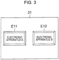
- the display control unit 41 causes the display unit 31 to display screen information (hereinafter referred to as "target apparatus designation screen information") that allows a user to designate, by a line-of-sight input, an icon (for example, an icon E11) representing a target apparatus to be operated (for example, "electronic apparatus A") among a plurality of icons E11 and E12 respectively representing the plurality of electronic apparatuses 20 (for example, “electronic apparatus A” and “electronic apparatus B").
- the display control unit 41 causes the display unit 31 to display screen information (hereinafter referred to as "function designation screen information") that allows a user to designate, by a line-of-sight input, an icon (for example, an icon E21) representing a function to be executed by a target apparatus to be operated (for example, "function 1") among a plurality of icons E21, E22, and E23 respectively representing a plurality of functions (for example, "function 1", “function 2", and "function 3").
- function designation screen information displayed screen information (hereinafter referred to as "function designation screen information") that allows a user to designate, by a line-of-sight input, an icon (for example, an icon E21) representing a function to be executed by a target apparatus to be operated (for example, "function 1") among a plurality of icons E21, E22, and E23 respectively representing a plurality of functions (for example, "function 1", “function 2", and "function 3").
- the display control unit 41 causes the display unit 31 to display screen information (hereinafter referred to as "execution condition designation screen information") that allows a user to designate, by a line-of-sight input, an icon (for example, an icon E31) representing an execution condition for a function to be executed by a target apparatus to be operated among a plurality of icons E31, E32, and E33 respectively representing a plurality of execution conditions (for example, "execution condition 1", “execution condition 2", and "execution condition 3").
- execution condition designation screen information displayed screen information (hereinafter referred to as "execution condition designation screen information") that allows a user to designate, by a line-of-sight input, an icon (for example, an icon E31) representing an execution condition for a function to be executed by a target apparatus to be operated among a plurality of icons E31, E32, and E33 respectively representing a plurality of execution conditions (for example, "execution condition 1", “execution condition 2", and
- “Function designation screen information” and “execution condition designation screen information” are examples of screen information that allows a user to designate, by a line-of-sight input, icons representing operation details (hereinafter referred to as “operation details designation screen information”). That is, “operation details” in this example include “function” and "execution condition”.
- a line of sight can be detected from an image of an eye of the user, based on the position of the iris, which is a movable point (a portion that moves relative to a reference point), relative to the inner corner of the eye, which is a reference point. For example, in a case where the iris of the left eye is far from the inner corner of the left eye, the user is looking left. On the other hand, in a case where the iris of the left eye is close to the inner corner of the left eye, the user is looking right.
- a line of sight can also be detected based on the position of the pupil, which is a movable point, relative to the position of the corneal reflection, which is a reference point. For example, in a case where the pupil of the left eye is closer than the corneal reflection to the outer corner side of the left eye, the user is looking left. In a case where the pupil of the left eye is closer than the corneal reflection to the inner corner side of the left eye, the user is looking right. In the case of using this method, the face of the user is irradiated with infrared rays and photographed by an infrared camera.
- the line-of-sight detecting unit 42 of this example detects a movement of a line of sight (i.e., continuously detects a line of sight), and the determining unit 44 of this example determines, based on the movement of the line of sight that has been detected, a target apparatus to be operated and operation details for the target apparatus.
- the determining unit 44 may determine, based on the movement of the line of sight that has been detected, at least one of a target apparatus to be operated or operation details.
- Examples of an action that is recognized by the action recognizing unit 43 include “head tilt” (an action of tilting the head) illustrated in Fig. 5A , “nod” (an action of shaking the head vertically) illustrated in Fig. 5B , and “head shake” (an action of shaking the head horizontally) illustrated in Fig. 5C . That is, in response to an instruction from the brain of the user who intends to perform an action, such as “head tilt”, “nod”, or “head shake”, muscles of the neck are moved and accordingly the head is moved. Action recognition is performed by directly detecting "a motion of the neck” by the neck motion sensor 52 of the neck-mounted terminal 33, not by detecting "a motion of the head", which is a result of a motion of the neck. Therefore, the action recognizing unit 43 is capable of appropriately recognizing an action intended by the user.
- the determining unit 44 determines, based on the line of sight detected by the line-of-sight detecting unit 42, at least one of a target apparatus to be operated or operation details, and confirms the determination, based on the motion of the neck detected by the neck-motion sensor 52 of the neck-mounted terminal 33.
- the determining unit 44 of this example makes a determination based on an action recognized by the action recognizing unit 43 by using a detection result obtained by the neck motion sensor 52. Such a case is also included in the concept of "to make a determination based on a motion of the neck” or "to confirm the determination based on a motion of the neck” in the present invention.
- the voice recognizing unit 45 recognizes a voice of the user, based on a vibration of the throat of the user detected at the neck of the user by the vibration sensor 54 of the neck-mounted terminal 33.
- the apparatus control unit 46 is an example of a "control unit" according to the present invention and controls, in accordance with a determination made by the determining unit 44, an electronic apparatus 20 which is a target apparatus to be operated.
- the communication unit 38 transmits an instruction to execute function 1 under execution condition 1 to electronic apparatus A which is a target apparatus to be operated.
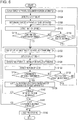
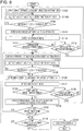
- Fig. 6 is a flowchart illustrating a flow of a process of a first example of an apparatus operation method using the apparatus operation device 30 of this embodiment. The process is executed by the CPU 40 in accordance with a program stored in advance in the storage unit 39.
- step S102 the display control unit 41 causes the display unit 31 to display the target apparatus designation screen information, as illustrated in Fig. 3 .
- step S104 the line-of-sight detecting unit 42 detects a line of sight of a user. For example, if the line of sight of the user is directed on the screen of the display unit 31, as illustrated in Fig. 7 , a position at which the line of sight of the user is directed (a line-of-sight position) on the screen of the display unit 31 is calculated based on an image (user image) captured by the line-of-sight detecting camera 32.
- step S108 the determining unit 44 determines, based on the line of sight detected in step S104, a target apparatus to be operated that has been designated by the user by using the line of sight.
- step S112 the neck motion sensor 52 of the neck-mounted terminal 33 detects a motion of the neck of the user and the action recognizing unit 43 recognizes an action of the user.
- step S114 the determining unit 44 determines whether or not the user has performed an action of a confirmation operation (for example, "nod" illustrated in Fig. 5B ).
- step S114 If it is determined that a confirmation operation has not been performed (NO in step S114), the process proceeds to step S116, where the determining unit 44 determines whether or not the user has performed an action of a cancellation operation (for example, "head shake" illustrated in Fig. 5C ). If it is determined that a cancellation operation has been performed (YES in step S116), the determination result about the target apparatus to be operated that is based on the line-of-sight detection result is cleared, and the process returns to step S102. If it is determined that a cancellation operation has not been performed (NO in step S116), the process returns to step S112, where detection of a motion of the neck (step S112) and determination of a confirmation operation (step S114) are repeated.
- a cancellation operation for example, "head shake" illustrated in Fig. 5C .
- step S114 If it is determined that a confirmation operation has been performed (YES in step S114), the process proceeds to step S122, where the display control unit 41 causes the display unit 31 to display the operation details designation screen information, as illustrated in Figs. 4A and 4B .
- the "function designation screen information" illustrated in Fig. 4A the "execution condition designation screen information” illustrated in Fig. 4B , or screen information including both the pieces of screen information is displayed as the operation details designation screen information.
- step S124 the line-of-sight detecting unit 42 detects a line of sight of the user. That is, the line-of-sight detecting unit 42 calculates, based on an image (user image) captured by the line-of-sight detecting camera 32, a position at which the line of sight of the user is directed (line-of-sight position) on the screen of the display unit 31.
- step S128, the determining unit 44 determines, based on the line of sight detected in step S124, operation details designated by the user by using the line of sight. That is, the determining unit 44 determines operation details for the electronic apparatus 20 as a target to be operated.
- step S132 the neck motion sensor 52 of the neck-mounted terminal 33 detects a motion of the neck of the user and the action recognizing unit 43 recognizes an action of the user.
- step S134 the determining unit 44 determines whether or not the user has performed an action of a confirmation operation (for example, "nod" illustrated in Fig. 5B ).
- step S134 the process proceeds to step S136, where the determining unit 44 determines whether or not the user has performed an action of a cancellation operation (for example, "head shake" illustrated in Fig. 5C ). If it is determined that a cancellation operation has been performed (YES in step S136), the determination result about the operation details that is based on the line-of-sight detection result is cleared, and the process returns to step S122. If it is determined that a cancellation operation has not been performed (NO in step S136), the process returns to step S132, where detection of a motion of the neck (step S132) and determination of a confirmation operation (step S134) are repeated.
- a cancellation operation for example, "head shake" illustrated in Fig. 5C .
- step S134 If it is determined that a confirmation operation has been performed (YES in step S134), the process proceeds to step S138, where the designated function of the designated target apparatus to be operated is executed in accordance with the designated operation details.
- step S142 it is determined whether or not to continue an operation of the same electronic apparatus 20 among the plurality of electronic apparatuses 20. In the case of continuing an operation of the same electronic apparatus 20 (YES in step S142), the process returns to step S122.
- step S144 it is determined whether or not to start an operation of another electronic apparatus 20. In the case of starting an operation of another electronic apparatus 20 (YES in step S144), the process returns to step S102.
- step S150 voice processing is executed to generate and output a report.
- the vibration sensor 54 of the neck-mounted terminal 33 detects a vibration of the throat at the neck of the user.
- the voice recognizing unit 45 recognizes, based on the detected vibration of the throat of the user, a voice of the user.
- the recognized voice is recorded. That is, only the voice of the person who is wearing the neck-mounted terminal 33 can be easily recorded, without ambient music or sound being recorded.
- Modes of recording a voice include a mode of performing recording inside the arithmetic unit 34, which is a main body unit of the apparatus operation device 30 (hereinafter referred to as an "inside recording mode"), and a mode of performing recording outside the arithmetic unit 34, which is a main body unit of the apparatus operation device 30 (hereinafter referred to as an "outside recording mode"), either of which may be used in the present invention.
- voice data is recorded in, for example, the storage unit 39 under control of the CPU 40.
- the storage unit 39 is an example of a "voice recording unit".
- voice data is output from the communication unit 38 (an example of a "voice data output unit") and is recorded in, for example, the database 22.
- the database 22 is an example of the "voice recording unit”.
- the voice data is written on a file and is transmitted to the database 22 through a local area network.
- voice processing (step S150) is performed after the operation of the apparatus has been finished in Fig. 6 , the present invention is not limited to such a case.
- Voices during the operation of the apparatus can be input, recognized, and recorded.
- instructions and conversations of medical doctors and so forth during surgery can be recorded as voice data, which can be used as evidence if a medical accident occurs or can be used to pass on medical technologies.
- step S150 After a report has been generated and output in the voice processing (step S150), the process ends.
- steps S108, S114, S116, S128, S134, and S136 are an example of a "determination step” in the present invention.
- Step S138 is an example of a "control step” in the present invention.
- line-of-sight detection by the line-of-sight detecting unit 42 and motion-of-neck detection by the neck-mounted terminal 33 are performed at different timings, but the line-of-sight detection and the motion-of-neck detection may be performed chronologically in parallel. In addition, each of the line-of-sight detection and the motion-of-neck detection may be performed continuously. In a case where such parallel control is performed, there is a possibility that the line-of-sight detection and the motion-of-neck detection are simultaneously performed.
- the line-of-sight detecting unit 42 in this example suspends detection of a line of sight upon detection of a motion of the neck being started by the neck-mounted terminal 33, and starts detection of a line of sight upon detection of a motion of the neck being finished by the neck-mounted terminal 33.
- the line-of-sight detecting unit 42 suspends detection of a line of sight when detection of a motion of the neck is started in step S112 or step S132 in Fig. 6 , and restarts detection of a line of sight when detection of a motion of the neck is finished.
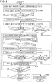
- Fig. 8 is a flowchart illustrating a flow of a process of a second example of the apparatus operation method using the apparatus operation device 30 of this embodiment. This process is executed by the CPU 40 in accordance with a program stored in advance in the storage unit 39.
- the same steps as those in the first example of this embodiment illustrated in Fig. 6 are denoted by the same numerals, and only different points will be described below.
- step S104A and step S124A are performed instead of the line-of-sight detection (step S104 and step S124) illustrated in Fig. 6 .
- step S104A and step S124A the motion of the neck detected by the neck-mounted terminal 33 is compared with a threshold (step S106 and step S126). If the detected motion of the neck is larger than the threshold, the line-of-sight detection is invalidated.
- line-of-sight detection in a state where the neck of the user is stationary or slightly moving is validated
- line-of-sight detection in a state where the neck of the user is largely moving is invalidated. This is because, in a state where the neck of the user is largely moving, the head of the user is also largely moving, and as a result there is a possibility that the line of sight of the user will largely move in an unconscious way and that a determination not intended by the user will be made.
- examples of "a case where the detected motion of the neck is larger than the threshold” include a case where the amount of the detected motion of the neck (i.e., the magnitude of a movement vector) is larger than the threshold, a case where an evaluation value representing a fluctuation of the direction of the detected motion of the neck (i.e., the direction of a movement vector) is larger than the threshold, and so forth. That is, examples of the magnitude of the motion of the neck of the user that affects the accuracy of line-of-sight detection include the magnitude of fluctuation of the direction of a movement vector, as well as the magnitude of the movement vector. In other words, the "detected motion of the neck” conceptually includes an evaluation value of a movement vector as well as the magnitude of the movement vector.
- Fig. 9 is a flowchart illustrating a flow of a process of a third example of the apparatus operation method using the apparatus operation device 30 of this embodiment. This process is executed by the CPU 40 in accordance with a program stored in advance in the storage unit 39.
- the same steps as those in the first example of this embodiment illustrated in Fig. 6 and those in the second example of this embodiment illustrated in Fig. 8 are denoted by the same numerals, and only different points will be described below.
- step S112A and step S132A line-of-sight detection and motion-of-neck detection are performed instead of the motion-of-neck detection (step S 112 and step S132) illustrated in Figs. 6 and 8 .
- step S112A and step S132A Based on the results of the line-of-sight detection and the motion-of-neck detection (step S112A and step S132A), it is determined whether or not a confirmation operation has been performed (step S114 and step S134) and whether or not a cancellation operation has been performed (step S116 and step S136).
- a method for changing a determination criterion value such as increasing a threshold to be compared with a detected motion of the neck, may be used.
- a determination criterion value such as increasing a threshold to be compared with a detected motion of the neck
- a determination is made by using a characteristic that, if the user moves the neck while gazing at a graphical user interface (GUI) element (for example, a button) on the screen of the display unit 31, a line-of-sight position on the screen of the display unit 31 is substantially constant or within a range of slight movements regardless of a motion of the neck.
- GUI graphical user interface
- determining whether or not the user has performed a confirmation operation by determining whether or not the user has performed a vertical head shake (nod) when the user shakes the head downward (or upward), the user's pupils move upward (or downward), so that it is detected that the magnitude of a movement vector of the neck becomes larger than a threshold for determining a motion of the neck, whereas it is detected that an amount of movement of a line-of-sight position on the screen becomes smaller than or equal to a threshold for determining a line-of-sight movement.
- determining whether or not the user has performed a cancellation operation by determining whether or not the user has performed a horizontal head shake when the user shakes the head leftward (or rightward), the user's pupils move rightward (or leftward), so that it is detected that the magnitude of a movement vector of the neck becomes larger than a threshold for determining a motion of the neck, whereas it is detected that an amount of movement of a line-of-sight position on the screen becomes smaller than or equal to a threshold for determining a line-of-sight movement.
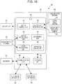
- Fig. 10 is a block diagram illustrating an example of an apparatus operation device 30 according to a second embodiment.
- the same elements as those in the apparatus operation device 30 of the first embodiment illustrated in Fig. 2 arc denoted by the same numerals, and only different points will be described below.
- a head-mounted terminal 60 is a terminal that is to be mounted on the head of a user, as illustrated in Fig. 11 , and includes a visual field camera 61 that captures an image of a photographic subject in a visual field of an eye of the user and obtains a visual field image, and a line-of-sight detecting camera 62 that captures an image of an eye of the user and obtains the image of the eye.
- the visual field camera 61 is located so as to be positioned near the left eye and/or the right eye when the head-mounted terminal 60 is mounted on the head of the user.
- visual field cameras 61 are located near the left eye and near the right eye, respectively, to obtain a stereo image that is made up of a visual field image of the left eye and a visual field image of the right eye, so that a relative three-dimensional positional relationship between each of the user's left eye and right eye and the display unit 31 can be calculated.
- the line-of-sight detecting camera 62 is located so that each of the left eye and the right eye becomes an imaging target when the head-mounted terminal 60 is mounted on the head of the user.
- a plurality of line-of-sight detecting cameras 62 may be provided to detect a line of sight reliably and stably.
- An apparatus operation method using the apparatus operation device 30 of this embodiment can be executed almost similarly to the process described above by using Fig. 6 in the first embodiment.
- a line-of-sight position of the user is calculated based on visual field images obtained by the visual field cameras 61 of the head-mounted terminal 60 and images of the eyes obtained by the line-of-sight detecting cameras 62 of the head-mounted terminal 60.
- the head-mounted terminal 60 of this example continues to transmit visual field images obtained by the visual field cameras 61 and images of the eyes obtained by the line-of-sight detecting cameras 62 to the arithmetic unit 34, which is a main body unit.
- the head-mounted terminal 60 transmits the visual filed images and the images of the eyes as still images at a regular or irregular time interval.
- the head-mounted terminal 60 may transmit the visual filed images and the images of the eyes as motion pictures at a regular frame rate.
- the line-of-sight detecting unit 42 of the arithmetic unit 34 calculates, based on visual field images (in this example, both a visual field image of the left eye and a visual field image of the right eye), a relative positional relationship between the eyes of the user and the screen of the display unit 31. In addition, the line-of-sight detecting unit 42 of the arithmetic unit 34 calculates, based on images of the eyes (in this example, both an image of the left eye and an image of the right eye), a relative positional relationship between a reference point and a movable point of the eyes (a portion that moves relative to the reference point).
- the line-of-sight detecting camera 62 captures an image by using visible light
- the inner corner and/or the outer corner of an eye is regarded as a reference point and the iris is regarded as a movable point.
- the line-of-sight detecting camera 62 captures an image by using infrared light
- the corneal reflection point is regarded as a reference point and the pupil is regarded as a movable point.
- the line-of-sight detecting unit 42 of the arithmetic unit 34 calculates, based on the calculated relative positional relationship between the eyes and the screen of the display unit 31 and the calculated positional relationship between the reference points and the movable points of the eyes, coordinates indicating a position at which the user is looking in a visual field image (a line-of-sight position in the visual field image). That is, the visual field image and the line-of-sight position are associated with each other.
- a line-of-sight position is represented as a range of a small circle having a certain radius and centered around the (x, y) coordinates. That is, as illustrated in Fig. 12B , it can be determined that the line of sight of the user is directed at a GUI element existing at a portion centered around the (x, y) coordinates in the visual field image (in the figure, the element E21 among three elements: the elements E21 to E23). As illustrated in Fig.
- line-of-sight detection is performed by using a so-called glasses-like head-mounted terminal 60.
- a line-of-sight position of a user can be accurately detected regardless of the orientation of the face or body of the user. That is, the user can naturally cast the eyes. Even if an angle of the head (the orientation of the face) of the user changes, line-of-sight detection can be accurately performed regardless of the change in the angle of the head.
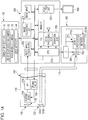
- Fig. 13 is an external view illustrating an electronic apparatus system (an endoscope system 10) in the case of using an endoscope apparatus 100 as each of the electronic apparatuses 20 illustrated in Fig. 1 .
- An endoscope main body 110 includes a handheld operation section 102 and an insertion section 104 that is connected to the handheld operation section 102.
- An operator operates the handheld operation section 102 while grasping handheld operation section 102 and inserts the insertion section 104 into a body of a subject to perform observation.
- the insertion section 104 is constituted by a flexible portion 112, a bending portion 114, and a distal end portion 116, which are arranged in this order from the handheld operation section 102 side.
- the distal end portion 116 is provided with an imaging optical system 130 (see Fig. 14 ), an illumination unit 123, a water supply nozzle 124, a forceps port 126, and so forth.
- an operation of an operation unit 208 (see Fig. 14 ) enables either or both of visible light and infrared light to be emitted from illumination lenses 123A and 123B of the illumination unit 123.
- an operation of the operation unit 208 enables washing water to be ejected from the water supply nozzle 124, so that a lens 132 of the imaging optical system 130 and the illumination lenses 123A and 123B can be washed.
- the forceps port 126 allows a treatment tool, which is used to extirpate or remove a tumor and which is not illustrated, to be inserted therethrough, and accordingly necessary treatment can be given to a subject by moving the treatment tool forward or backward as appropriate.
- the lens 132 of the imaging optical system 130 is disposed on a distal end surface of the distal end portion 116.
- An imaging device 134 of a complementary metal-oxide semiconductor (CMOS) type, a driving circuit 136, and an analog front end (AFE) 138 are disposed behind the lens 132, so as to output an image signal.
- CMOS complementary metal-oxide semiconductor
- AFE analog front end
- An observation image that has been taken through the lens 132 and so forth is formed on a light reception surface of the imaging device 134, converted into an electric signal, output to an endoscope processor 200 through a signal cable that is not illustrated, and converted into a video signal. Accordingly, the observation image is displayed on a monitor 400, which is connected to the endoscope processor 200.
- Fig. 15 is a diagram illustrating a state where the insertion section 104 of the endoscope apparatus 100 is inserted into a subject, and illustrating a state where an observation image is obtained via the imaging optical system 130.
- a reference symbol IA denotes an imaging range
- a reference symbol tm denotes a tumor (a black raised portion in Fig. 15 ).
- the illumination lens 123A (for visible light) and the illumination lens 123B (for infrared light) of the illumination unit 123 are disposed next to the lens 132 on the distal end surface of the distal end portion 116.
- An emission end of a light guide 170 which will be described below, is disposed behind the illumination lenses 123A and 123B.
- the light guide 170 is inserted through the insertion section 104, the handheld operation section 102, and a universal cable 106, and an incidence end of the light guide 170 is located in a light guide connector 108.
- a light source device 300 is constituted by a light source 310, a diaphragm 330, a condenser lens 340, and so forth, and causes illumination light to enter the light guide 170.
- the light source 310 includes a visible light source 310A and an infrared light source 310B and is capable of emitting one or both of visible light and infrared light. Accordingly, with the light guide connector 108 (see Fig. 13 ) being connected to the light source device 300, illumination light emitted by the light source device 300 is transmitted to the illumination lenses 123A and 123B through the light guide 170 and is applied to an observation range from the illumination lenses 123A and 123B.
- an image input controller 202 receives an image signal output from the endoscope apparatus 100, an image processing unit 204 performs necessary image processing thereon, and a video output unit 206 outputs a resulting image signal. Accordingly, an observation image is displayed on the monitor 400.
- These processes are performed under control of a central processing unit (CPU) 210.
- the image processing unit 204 performs, in addition to image processing such as white balance adjustment, switching or superimposition of an image displayed on the monitor 400, electronic zoom processing, display and switching of an image according to an operation mode, or extraction of a specific component (for example, a brightness signal) from an image signal.
- the endoscope processor 200 includes the operation unit 208.
- the operation unit 208 includes an operation mode setting/selecting switch, a water supply instruction button, or the like (not illustrated), and is capable of performing an operation of emitting visible light or infrared light.
- the target apparatus to be operated is the endoscope apparatus 100, which is a medical apparatus, with reference to Fig. 13 .
- the target apparatus to be operated in the present invention is not necessarily a medical apparatus.
- the embodiments are applicable to an operation of a mobile apparatus, such as a smartphone, a tablet terminal, or a game machine, as well as a medical apparatus, and to an operation of an apparatus under a situation where it is impossible to freely use both hands while operating an apparatus, for example, driving a car, or a situation where the arrangement of an apparatus is restricted.
- the target apparatus to be operated is not limited to a single apparatus. One of a plurality of apparatuses may be selected by using a line of sight and a motion of the neck.
- a gesture may be performed by moving only the neck without moving the head, depending on the target apparatus to be operated, the usage situation of the apparatus, the type or importance of an operation, or the like.
- a user as a target of line-of-sight detection and a user as a target of gesture detection may be different from each other.
Description
- The present invention relates to an apparatus operation device including a line-of-sight detecting unit, a determining unit that determines at least a target apparatus based on a detected line of sight, and a control unit that controls the target apparatus. It also relates to an apparatus operation method, and an electronic apparatus system, and particularly relates to a technique for operating an apparatus by using a line of sight and a motion of the neck of a user. Apparatus of the above type is known from
US2013/147686 . - Various types of apparatuses are typically operated by a user with his/her hand or foot. However, depending on a type or usage situation of an apparatus, restrictions may be imposed on a user's action or the arrangement of the apparatus or an operation device. For example, in an operation of a mobile apparatus, such as a smartphone or game machine, driving of a car, or an operation of a medical apparatus, a user may be unable to freely use both hands. As for a medical apparatus, the user may need to peel off/put on gloves or wash hands before/after operating the apparatus. That is, in operation techniques using a hand or foot, it may be difficult to smoothly perform an operation.
- As operation techniques not using a hand or foot, operation techniques using a line of sight and a gesture are known (see, for example,
JP2014-126997A JP2000-163196A JP2001-100903A JP2007-195892A -
JP2014-126997A JP2000-163196A -
JP2001-100903A -
JP2007-195892A JP2007-195892A - In addition, an operation technique using a voice input is known.
JP2001-299691A
US 2014/300532 A shows an apparatus for controlling a near-eye-display. A collar at the user's neck detects movements of the user's head. - However, there has not been provided an operation technique that enables a user to easily perform an operation even if both hands are occupied and that enables an operation intended by the user to be appropriately detected and performed.
- In the techniques described in
JP2014-126997A JP2000-163196A - Also in the techniques described in
JP2001-100903A JP2007-195892A JP2001-299691A - On the other hand, under circumstances where there is an issue of medical errors, recording of conversation between medical doctors may be considered to determine the propriety of surgery. However, music is played during surgery in a surgery room and a plurality of people is involved in the surgery. Thus, in the voice input according to
JP2001-299691 - The present invention has been made in view of the above-described circumstances, and an object of the present invention is to provide an apparatus operation device, an apparatus operation method, and an electronic apparatus system that enable a user to easily perform an operation even if both hands are occupied and that enable an operation intended by the user to be appropriately detected and performed.
- To achieve the above-described object, an apparatus operation device according to a first aspect of the present invention includes the features of
claim 1. - According to this aspect, an operation can be easily performed even if both hands of a user are occupied, and an operation intended by the user can be appropriately detected and performed.
- In an apparatus operation device according to a second aspect of the present invention, the determining unit determines, based on the line of sight that has been detected, at least one of the target apparatus or the operation details, and confirms the determination, based on the motion of the neck that has been detected.
- In an apparatus operation device according to a third aspect of the present invention, the line-of-sight detecting unit detects a movement of the line of sight, and the determining unit determines, based on the movement of the line of sight that has been detected, at least one of the target apparatus or the operation details.
- In an apparatus operation device according to a fourth aspect of the present invention, the operation details include a function that the control unit causes the target apparatus to execute, and an execution condition for the function.
- In an apparatus operation device according to a fifth aspect of the present invention, the apparatus operation device includes a voice recognizing unit that recognizes a voice of the user by using a vibration of a throat of the user, the vibration being detected by the neck-mounted terminal.
- In an apparatus operation device according to a sixth aspect of the present invention, the apparatus operation device includes a voice recording unit that records the voice that has been recognized.
- To achieve the above-described object, an apparatus operation method according to the present invention is an apparatus operation method defined by claim 7.
- To achieve the above-described object, an electronic apparatus system according to the present invention includes the apparatus operation device and an electronic apparatus which is the target apparatus.
- The electronic apparatus is a medical apparatus, for example.
- According to the present invention, an operation can be easily performed even if both hands of a user are occupied, and an operation intended by the user can be appropriately detected and performed.
- The embodiments of
figures 8 and9 and their respective description, are illustrative examples, not forming part of the invention. -
-
Fig. 1 is a diagram illustrating the overall configuration of an example of an electronic apparatus system according to a first embodiment; -
Fig. 2 is a block diagram illustrating an example of an apparatus operation device according to the first embodiment; -
Fig. 3 is a diagram illustrating an example of screen information for designating a target apparatus to be operated; -
Figs. 4A and 4B are diagrams illustrating examples of screen information for designating operation details; -
Figs. 5A to 5C are explanatory diagrams for describing detection of a motion of a neck; -
Fig. 6 is a flowchart illustrating a flow of a process of a first example of an apparatus operation method using the apparatus operation device according to the first embodiment; -
Fig. 7 is an explanatory diagram for describing detection of a line of sight in the apparatus operation device according to the first embodiment; -
Fig. 8 is a flowchart illustrating a flow of a process of a second example of the apparatus operation method using the apparatus operation device according to the first embodiment; -
Fig. 9 is a flowchart illustrating a flow of a process of a third example of the apparatus operation method using the apparatus operation device according to the first embodiment; -
Fig. 10 is a block diagram illustrating an example of an apparatus operation device according to a second embodiment; -
Fig. 11 is an explanatory diagram for describing a visual field image and images of eyes that are captured by a head-mounted terminal in the apparatus operation device according to the second embodiment; -
Figs. 12A to 12C are explanatory diagrams for describing an example of detection of a line of sight and determination of an operation in the apparatus operation device according to the second embodiment; -
Fig. 13 is a diagram illustrating the overall configuration of an example of an electronic apparatus system in a case where an endoscope apparatus is used as an electronic apparatus; -
Fig. 14 is a block diagram illustrating the configuration of the electronic apparatus system illustrated inFig. 13 ; and -
Fig. 15 is a diagram illustrating a state of observation using the endoscope apparatus. - Hereinafter, embodiments of an apparatus operation device, an apparatus operation method, and an electronic apparatus system according to the present invention will be described with reference to the attached drawings.
-
Fig. 1 is a diagram illustrating the overall configuration of an example of an electronic apparatus system according to a first embodiment of the present invention, andFig. 2 is a block diagram illustrating an example of an apparatus operation device according to the first embodiment of the present invention. - As illustrated in
Fig. 1 , anelectronic apparatus system 10 includeselectronic apparatuses 20, each of which is a target apparatus to be operated, and anapparatus operation device 30 that controls theelectronic apparatuses 20. - The
apparatus operation device 30 includes a display unit 31 (also referred to as a "display") that performs display for a user, a line-of-sight detecting camera 32 that captures an image of the face of the user to detect a line of sight of the user, a neck-mountedterminal 33 that is mounted around the neck of the user and detects a motion of the neck of the user, and anarithmetic unit 34 that serves as a main body unit, which controls thedisplay unit 31, the line-of-sight detecting camera 32, and the neck-mountedterminal 33, and that performs various arithmetic operations. - The
display unit 31 is constituted by a display device, such as a liquid crystal display device. - The line-of-
sight detecting camera 32 is located near thedisplay unit 31, captures an image of at least an eye of the user to generate an image (hereinafter referred to as a "user image") including the image of the eye, and outputs the generated image. In the case of extracting only the portion of an eye in the face of the user, the extraction may be performed by using a function of the line-of-sight detecting camera 32, or a function of the extraction may be provided in thearithmetic unit 34. To detect a line of sight reliably and stably, a plurality of line-of-sight detecting cameras 32 may be provided. - The neck-mounted
terminal 33 is a terminal that is to be mounted around the neck of the user and includes, as illustrated inFig. 1 , aneck motion sensor 52 that detects a motion of the neck of the user and avibration sensor 54 that detects a vibration of the throat of the user on the neck. - As the
neck motion sensor 52, a sensor device, such as a myoelectric sensor that detects a motion of a neck muscle, a distortion sensor, or an acceleration sensor, is used. A sensor device other than these sensors may be used. As "a motion of the neck", any of a motion of a neck muscle, a motion of a neck bone, or a motion of a neck surface (i.e., a motion of a neck skin) may be detected by theneck motion sensor 52. A plurality of types of sensor devices may be used to perform detection. - As the
vibration sensor 54, an acceleration sensor that detects a vibration of a neck bone is used, for example. Another type of sensor may be used. - A single sensor device may be implemented as the
neck motion sensor 52 and thevibration sensor 54, and the single sensor device may be caused to detect a motion of the neck and a vibration of the throat. For example, a single acceleration sensor is implemented as theneck motion sensor 52 and thevibration sensor 54, a low-frequency component is extracted from an output signal of the acceleration sensor to generate a signal representing a motion of the neck, and a high-frequency component is extracted from the output signal to generate a signal representing a vibration of the throat. - As illustrated in
Fig. 2 , thearithmetic unit 34 includes acommunication unit 38 that communicates with the plurality ofelectronic apparatuses 20, astorage unit 39 that stores a program for controlling the operation of theelectronic apparatuses 20 and information that is necessary to execute the program, and a central processing unit (CPU) 40 that controls the individual units of theapparatus operation device 30 by executing the program stored in thestorage unit 39. - The
communication unit 38 is constituted by a communication device that communicates with theelectronic apparatuses 20.Fig. 1 illustrates a case where thecommunication unit 38 communicates with theelectronic apparatuses 20 in a wireless manner, but thecommunication unit 38 may communicate with theelectronic apparatuses 20 in a wired manner through a local area network or the like. In addition, thecommunication unit 38 may communicate with a device outside the arithmetic unit 34 (for example, a database 22), which is not illustrated inFig. 1 , through a local area network or the like. - The
storage unit 39 includes a nonvolatile storage device that stores programs and the like and a readable/writable storage device that is used as a working area of the programs. - The
CPU 40 includes, as illustrated inFig. 2 , adisplay control unit 41 that performs display control for thedisplay unit 31; a line-of-sight detecting unit 42 that detects, based on a user image output from the line-of-sight detecting camera 32, a line of sight of a user; anaction recognizing unit 43 that recognizes, based on a motion of the neck of the user that has been detected by theneck motion sensor 52 of the neck-mountedterminal 33, an action of the head of the user; a determiningunit 44 that determines, based on the line of sight detected by the line-of-sight detecting unit 42 and the action of the head of the user that has been recognized based on the motion of the neck of the user, at least one of a target apparatus to be operated or operation details for the target apparatus; avoice recognizing unit 45 that recognizes a voice of the user by using a vibration of the throat of the user detected at the neck of the user by thevibration sensor 54 of the neck-mountedterminal 33; and anapparatus control unit 46 that controls theelectronic apparatuses 20 in accordance with the determination made by the determiningunit 44. - The
display control unit 41 has a function of causing thedisplay unit 31 to display screen information that is necessary for a user operation. - As illustrated in
Fig. 3 , thedisplay control unit 41 causes thedisplay unit 31 to display screen information (hereinafter referred to as "target apparatus designation screen information") that allows a user to designate, by a line-of-sight input, an icon (for example, an icon E11) representing a target apparatus to be operated (for example, "electronic apparatus A") among a plurality of icons E11 and E12 respectively representing the plurality of electronic apparatuses 20 (for example, "electronic apparatus A" and "electronic apparatus B"). - Also, as illustrated in
Fig. 4A , thedisplay control unit 41 causes thedisplay unit 31 to display screen information (hereinafter referred to as "function designation screen information") that allows a user to designate, by a line-of-sight input, an icon (for example, an icon E21) representing a function to be executed by a target apparatus to be operated (for example, "function 1") among a plurality of icons E21, E22, and E23 respectively representing a plurality of functions (for example, "function 1", "function 2", and "function 3"). - Also, as illustrated in
Fig. 4B , thedisplay control unit 41 causes thedisplay unit 31 to display screen information (hereinafter referred to as "execution condition designation screen information") that allows a user to designate, by a line-of-sight input, an icon (for example, an icon E31) representing an execution condition for a function to be executed by a target apparatus to be operated among a plurality of icons E31, E32, and E33 respectively representing a plurality of execution conditions (for example, "execution condition 1", "execution condition 2", and "execution condition 3"). - "Function designation screen information" and "execution condition designation screen information" are examples of screen information that allows a user to designate, by a line-of-sight input, icons representing operation details (hereinafter referred to as "operation details designation screen information"). That is, "operation details" in this example include "function" and "execution condition".
- Next, line-of-sight detection performed by the line-of-
sight detecting unit 42 will be described. - A line of sight (point of gaze) can be detected from an image of an eye of the user, based on the position of the iris, which is a movable point (a portion that moves relative to a reference point), relative to the inner corner of the eye, which is a reference point. For example, in a case where the iris of the left eye is far from the inner corner of the left eye, the user is looking left. On the other hand, in a case where the iris of the left eye is close to the inner corner of the left eye, the user is looking right.
- A line of sight can also be detected based on the position of the pupil, which is a movable point, relative to the position of the corneal reflection, which is a reference point. For example, in a case where the pupil of the left eye is closer than the corneal reflection to the outer corner side of the left eye, the user is looking left. In a case where the pupil of the left eye is closer than the corneal reflection to the inner corner side of the left eye, the user is looking right. In the case of using this method, the face of the user is irradiated with infrared rays and photographed by an infrared camera.
- The line-of-
sight detecting unit 42 of this example detects a movement of a line of sight (i.e., continuously detects a line of sight), and the determiningunit 44 of this example determines, based on the movement of the line of sight that has been detected, a target apparatus to be operated and operation details for the target apparatus. The determiningunit 44 may determine, based on the movement of the line of sight that has been detected, at least one of a target apparatus to be operated or operation details. - Next, a specific example of action recognition by the
action recognizing unit 43 will be described. - Examples of an action that is recognized by the
action recognizing unit 43 include "head tilt" (an action of tilting the head) illustrated inFig. 5A , "nod" (an action of shaking the head vertically) illustrated inFig. 5B , and "head shake" (an action of shaking the head horizontally) illustrated inFig. 5C . That is, in response to an instruction from the brain of the user who intends to perform an action, such as "head tilt", "nod", or "head shake", muscles of the neck are moved and accordingly the head is moved. Action recognition is performed by directly detecting "a motion of the neck" by theneck motion sensor 52 of the neck-mountedterminal 33, not by detecting "a motion of the head", which is a result of a motion of the neck. Therefore, theaction recognizing unit 43 is capable of appropriately recognizing an action intended by the user. - The determining
unit 44 determines, based on the line of sight detected by the line-of-sight detecting unit 42, at least one of a target apparatus to be operated or operation details, and confirms the determination, based on the motion of the neck detected by the neck-motion sensor 52 of the neck-mountedterminal 33. The determiningunit 44 of this example makes a determination based on an action recognized by theaction recognizing unit 43 by using a detection result obtained by theneck motion sensor 52. Such a case is also included in the concept of "to make a determination based on a motion of the neck" or "to confirm the determination based on a motion of the neck" in the present invention. - The
voice recognizing unit 45 recognizes a voice of the user, based on a vibration of the throat of the user detected at the neck of the user by thevibration sensor 54 of the neck-mountedterminal 33. - The
apparatus control unit 46 is an example of a "control unit" according to the present invention and controls, in accordance with a determination made by the determiningunit 44, anelectronic apparatus 20 which is a target apparatus to be operated. - For example, if the determining
unit 44 determines that "electronic apparatus A" has been designated from the target apparatus designation screen information illustrated inFig. 3 , determines that "function 1" has been designated from the function designation screen information illustrated inFig. 4A , and determines that "execution condition 1" has been designated from the execution condition designation screen information illustrated inFig. 4B , thecommunication unit 38 transmits an instruction to executefunction 1 underexecution condition 1 to electronic apparatus A which is a target apparatus to be operated. -
Fig. 6 is a flowchart illustrating a flow of a process of a first example of an apparatus operation method using theapparatus operation device 30 of this embodiment. The process is executed by theCPU 40 in accordance with a program stored in advance in thestorage unit 39. - Upon the process being started, in step S102, the
display control unit 41 causes thedisplay unit 31 to display the target apparatus designation screen information, as illustrated inFig. 3 . - Subsequently, the process proceeds to step S104, where the line-of-
sight detecting unit 42 detects a line of sight of a user. For example, if the line of sight of the user is directed on the screen of thedisplay unit 31, as illustrated inFig. 7 , a position at which the line of sight of the user is directed (a line-of-sight position) on the screen of thedisplay unit 31 is calculated based on an image (user image) captured by the line-of-sight detecting camera 32. - Subsequently, the process proceeds to step S108, where the determining
unit 44 determines, based on the line of sight detected in step S104, a target apparatus to be operated that has been designated by the user by using the line of sight. - Subsequently, the process proceeds to step S112, where the
neck motion sensor 52 of the neck-mountedterminal 33 detects a motion of the neck of the user and theaction recognizing unit 43 recognizes an action of the user. - Subsequently, the process proceeds to step S114, where the determining
unit 44 determines whether or not the user has performed an action of a confirmation operation (for example, "nod" illustrated inFig. 5B ). - If it is determined that a confirmation operation has not been performed (NO in step S114), the process proceeds to step S116, where the determining
unit 44 determines whether or not the user has performed an action of a cancellation operation (for example, "head shake" illustrated inFig. 5C ). If it is determined that a cancellation operation has been performed (YES in step S116), the determination result about the target apparatus to be operated that is based on the line-of-sight detection result is cleared, and the process returns to step S102. If it is determined that a cancellation operation has not been performed (NO in step S116), the process returns to step S112, where detection of a motion of the neck (step S112) and determination of a confirmation operation (step S114) are repeated. - If it is determined that a confirmation operation has been performed (YES in step S114), the process proceeds to step S122, where the
display control unit 41 causes thedisplay unit 31 to display the operation details designation screen information, as illustrated inFigs. 4A and 4B . For example, the "function designation screen information" illustrated inFig. 4A , the "execution condition designation screen information" illustrated inFig. 4B , or screen information including both the pieces of screen information is displayed as the operation details designation screen information. - Subsequently, the process proceeds to step S124, where the line-of-
sight detecting unit 42 detects a line of sight of the user. That is, the line-of-sight detecting unit 42 calculates, based on an image (user image) captured by the line-of-sight detecting camera 32, a position at which the line of sight of the user is directed (line-of-sight position) on the screen of thedisplay unit 31. - Subsequently, the process proceeds to step S128, where the determining
unit 44 determines, based on the line of sight detected in step S124, operation details designated by the user by using the line of sight. That is, the determiningunit 44 determines operation details for theelectronic apparatus 20 as a target to be operated. - Subsequently, the process proceeds to step S132, where the
neck motion sensor 52 of the neck-mountedterminal 33 detects a motion of the neck of the user and theaction recognizing unit 43 recognizes an action of the user. - Subsequently, the process proceeds to step S134, where the determining
unit 44 determines whether or not the user has performed an action of a confirmation operation (for example, "nod" illustrated inFig. 5B ). - If it is determined that a confirmation operation has not been performed (NO in step S134), the process proceeds to step S136, where the determining
unit 44 determines whether or not the user has performed an action of a cancellation operation (for example, "head shake" illustrated inFig. 5C ). If it is determined that a cancellation operation has been performed (YES in step S136), the determination result about the operation details that is based on the line-of-sight detection result is cleared, and the process returns to step S122. If it is determined that a cancellation operation has not been performed (NO in step S136), the process returns to step S132, where detection of a motion of the neck (step S132) and determination of a confirmation operation (step S134) are repeated. - If it is determined that a confirmation operation has been performed (YES in step S134), the process proceeds to step S138, where the designated function of the designated target apparatus to be operated is executed in accordance with the designated operation details.
- Subsequently, the process proceeds to step S142, where it is determined whether or not to continue an operation of the same
electronic apparatus 20 among the plurality ofelectronic apparatuses 20. In the case of continuing an operation of the same electronic apparatus 20 (YES in step S142), the process returns to step S122. In step S144, it is determined whether or not to start an operation of anotherelectronic apparatus 20. In the case of starting an operation of another electronic apparatus 20 (YES in step S144), the process returns to step S102. - In the case of finishing the operation of the same and another electronic apparatus 20 (NO in step S144), the process proceeds to step S150, where voice processing is executed to generate and output a report.
- The details of the voice processing in step S150 will be described. First, the
vibration sensor 54 of the neck-mountedterminal 33 detects a vibration of the throat at the neck of the user. Subsequently, thevoice recognizing unit 45 recognizes, based on the detected vibration of the throat of the user, a voice of the user. Subsequently, the recognized voice is recorded. That is, only the voice of the person who is wearing the neck-mountedterminal 33 can be easily recorded, without ambient music or sound being recorded. - Modes of recording a voice include a mode of performing recording inside the
arithmetic unit 34, which is a main body unit of the apparatus operation device 30 (hereinafter referred to as an "inside recording mode"), and a mode of performing recording outside thearithmetic unit 34, which is a main body unit of the apparatus operation device 30 (hereinafter referred to as an "outside recording mode"), either of which may be used in the present invention. In the inside recording mode, voice data is recorded in, for example, thestorage unit 39 under control of theCPU 40. In this example, thestorage unit 39 is an example of a "voice recording unit". In the outside recording mode, voice data is output from the communication unit 38 (an example of a "voice data output unit") and is recorded in, for example, thedatabase 22. In this example, thedatabase 22 is an example of the "voice recording unit". For example, the voice data is written on a file and is transmitted to thedatabase 22 through a local area network. - Although voice processing (step S150) is performed after the operation of the apparatus has been finished in
Fig. 6 , the present invention is not limited to such a case. Voices during the operation of the apparatus can be input, recognized, and recorded. For example, instructions and conversations of medical doctors and so forth during surgery can be recorded as voice data, which can be used as evidence if a medical accident occurs or can be used to pass on medical technologies. - After a report has been generated and output in the voice processing (step S150), the process ends.
- In
Fig. 6 , steps S108, S114, S116, S128, S134, and S136 are an example of a "determination step" in the present invention. Step S138 is an example of a "control step" in the present invention. - In
Fig. 6 , line-of-sight detection by the line-of-sight detecting unit 42 and motion-of-neck detection by the neck-mountedterminal 33 are performed at different timings, but the line-of-sight detection and the motion-of-neck detection may be performed chronologically in parallel. In addition, each of the line-of-sight detection and the motion-of-neck detection may be performed continuously. In a case where such parallel control is performed, there is a possibility that the line-of-sight detection and the motion-of-neck detection are simultaneously performed. However, the line-of-sight detecting unit 42 in this example suspends detection of a line of sight upon detection of a motion of the neck being started by the neck-mountedterminal 33, and starts detection of a line of sight upon detection of a motion of the neck being finished by the neck-mountedterminal 33. For example, the line-of-sight detecting unit 42 suspends detection of a line of sight when detection of a motion of the neck is started in step S112 or step S132 inFig. 6 , and restarts detection of a line of sight when detection of a motion of the neck is finished. -
Fig. 8 is a flowchart illustrating a flow of a process of a second example of the apparatus operation method using theapparatus operation device 30 of this embodiment. This process is executed by theCPU 40 in accordance with a program stored in advance in thestorage unit 39. The same steps as those in the first example of this embodiment illustrated inFig. 6 are denoted by the same numerals, and only different points will be described below. - In this example, line-of-sight detection and motion-of-neck detection (step S104A and step S124A) are performed instead of the line-of-sight detection (step S104 and step S124) illustrated in
Fig. 6 . After the line-of-sight detection and the motion-of-neck detection (step S104A and step S124A), the motion of the neck detected by the neck-mountedterminal 33 is compared with a threshold (step S106 and step S126). If the detected motion of the neck is larger than the threshold, the line-of-sight detection is invalidated. - That is, in this example, line-of-sight detection in a state where the neck of the user is stationary or slightly moving is validated, whereas line-of-sight detection in a state where the neck of the user is largely moving is invalidated. This is because, in a state where the neck of the user is largely moving, the head of the user is also largely moving, and as a result there is a possibility that the line of sight of the user will largely move in an unconscious way and that a determination not intended by the user will be made.
- Here, examples of "a case where the detected motion of the neck is larger than the threshold" include a case where the amount of the detected motion of the neck (i.e., the magnitude of a movement vector) is larger than the threshold, a case where an evaluation value representing a fluctuation of the direction of the detected motion of the neck (i.e., the direction of a movement vector) is larger than the threshold, and so forth. That is, examples of the magnitude of the motion of the neck of the user that affects the accuracy of line-of-sight detection include the magnitude of fluctuation of the direction of a movement vector, as well as the magnitude of the movement vector. In other words, the "detected motion of the neck" conceptually includes an evaluation value of a movement vector as well as the magnitude of the movement vector.
-
Fig. 9 is a flowchart illustrating a flow of a process of a third example of the apparatus operation method using theapparatus operation device 30 of this embodiment. This process is executed by theCPU 40 in accordance with a program stored in advance in thestorage unit 39. The same steps as those in the first example of this embodiment illustrated inFig. 6 and those in the second example of this embodiment illustrated inFig. 8 are denoted by the same numerals, and only different points will be described below. - In this example, line-of-sight detection and motion-of-neck detection (step S112A and step S132A) are performed instead of the motion-of-neck detection (
step S 112 and step S132) illustrated inFigs. 6 and8 . Based on the results of the line-of-sight detection and the motion-of-neck detection (step S112A and step S132A), it is determined whether or not a confirmation operation has been performed (step S114 and step S134) and whether or not a cancellation operation has been performed (step S116 and step S136). - That is, in this example, it is determined based on not only a result of motion-of-neck detection but also a result of line-of-sight detection whether or not to confirm the determination of a target apparatus to be operated and operation details and whether or not to cancel the determination of the target apparatus to be performed and the operation details. This is because, if a determination of whether or not the user has performed a confirmation operation or a cancellation operation is made based on only a motion of the neck, a wrong determination that the user has performed a confirmation operation or a cancellation operation may be made if the user moves the neck in an unconscious way. As a method for avoiding such a wrong determination, a method for changing a determination criterion value, such as increasing a threshold to be compared with a detected motion of the neck, may be used. However, if the user is forced to make a larger motion of the neck, that is, to make a forced action, to avoid a wrong determination, the user is unable to perform a smooth operation, which may make the user tired. Thus, a determination is made by using a characteristic that, if the user moves the neck while gazing at a graphical user interface (GUI) element (for example, a button) on the screen of the
display unit 31, a line-of-sight position on the screen of thedisplay unit 31 is substantially constant or within a range of slight movements regardless of a motion of the neck. - For example, in the case of determining whether or not the user has performed a confirmation operation by determining whether or not the user has performed a vertical head shake (nod), when the user shakes the head downward (or upward), the user's pupils move upward (or downward), so that it is detected that the magnitude of a movement vector of the neck becomes larger than a threshold for determining a motion of the neck, whereas it is detected that an amount of movement of a line-of-sight position on the screen becomes smaller than or equal to a threshold for determining a line-of-sight movement. In the case of determining whether or not the user has performed a cancellation operation by determining whether or not the user has performed a horizontal head shake, when the user shakes the head leftward (or rightward), the user's pupils move rightward (or leftward), so that it is detected that the magnitude of a movement vector of the neck becomes larger than a threshold for determining a motion of the neck, whereas it is detected that an amount of movement of a line-of-sight position on the screen becomes smaller than or equal to a threshold for determining a line-of-sight movement.
-
Fig. 10 is a block diagram illustrating an example of anapparatus operation device 30 according to a second embodiment. InFig. 10 , the same elements as those in theapparatus operation device 30 of the first embodiment illustrated inFig. 2 arc denoted by the same numerals, and only different points will be described below. - A head-mounted
terminal 60 is a terminal that is to be mounted on the head of a user, as illustrated inFig. 11 , and includes avisual field camera 61 that captures an image of a photographic subject in a visual field of an eye of the user and obtains a visual field image, and a line-of-sight detecting camera 62 that captures an image of an eye of the user and obtains the image of the eye. Thevisual field camera 61 is located so as to be positioned near the left eye and/or the right eye when the head-mountedterminal 60 is mounted on the head of the user. In this example,visual field cameras 61 are located near the left eye and near the right eye, respectively, to obtain a stereo image that is made up of a visual field image of the left eye and a visual field image of the right eye, so that a relative three-dimensional positional relationship between each of the user's left eye and right eye and thedisplay unit 31 can be calculated. The line-of-sight detecting camera 62 is located so that each of the left eye and the right eye becomes an imaging target when the head-mountedterminal 60 is mounted on the head of the user. A plurality of line-of-sight detecting cameras 62 (for example, two line-of-sight detecting cameras: a line-of-sight detecting camera for capturing an image of the left eye and a line-of-sight detecting camera for capturing an image of the right eye) may be provided to detect a line of sight reliably and stably. - An apparatus operation method using the
apparatus operation device 30 of this embodiment can be executed almost similarly to the process described above by usingFig. 6 in the first embodiment. In the second embodiment, in line-of-sight detection by the line-of-sight detecting unit 42 (step S104 inFig. 6 ), a line-of-sight position of the user is calculated based on visual field images obtained by thevisual field cameras 61 of the head-mountedterminal 60 and images of the eyes obtained by the line-of-sight detecting cameras 62 of the head-mountedterminal 60. - The head-mounted
terminal 60 of this example continues to transmit visual field images obtained by thevisual field cameras 61 and images of the eyes obtained by the line-of-sight detecting cameras 62 to thearithmetic unit 34, which is a main body unit. For example, the head-mountedterminal 60 transmits the visual filed images and the images of the eyes as still images at a regular or irregular time interval. The head-mountedterminal 60 may transmit the visual filed images and the images of the eyes as motion pictures at a regular frame rate. - The line-of-
sight detecting unit 42 of thearithmetic unit 34 calculates, based on visual field images (in this example, both a visual field image of the left eye and a visual field image of the right eye), a relative positional relationship between the eyes of the user and the screen of thedisplay unit 31. In addition, the line-of-sight detecting unit 42 of thearithmetic unit 34 calculates, based on images of the eyes (in this example, both an image of the left eye and an image of the right eye), a relative positional relationship between a reference point and a movable point of the eyes (a portion that moves relative to the reference point). In a case where the line-of-sight detecting camera 62 captures an image by using visible light, for example, the inner corner and/or the outer corner of an eye is regarded as a reference point and the iris is regarded as a movable point. In a case where the line-of-sight detecting camera 62 captures an image by using infrared light, for example, the corneal reflection point is regarded as a reference point and the pupil is regarded as a movable point. - Subsequently, the line-of-
sight detecting unit 42 of thearithmetic unit 34 calculates, based on the calculated relative positional relationship between the eyes and the screen of thedisplay unit 31 and the calculated positional relationship between the reference points and the movable points of the eyes, coordinates indicating a position at which the user is looking in a visual field image (a line-of-sight position in the visual field image). That is, the visual field image and the line-of-sight position are associated with each other. - As illustrated in
Fig. 12A , in a case where the horizontal direction of a visual field image is an X direction and the vertical direction is a Y direction, a line-of-sight position is represented as a range of a small circle having a certain radius and centered around the (x, y) coordinates. That is, as illustrated inFig. 12B , it can be determined that the line of sight of the user is directed at a GUI element existing at a portion centered around the (x, y) coordinates in the visual field image (in the figure, the element E21 among three elements: the elements E21 to E23). As illustrated inFig. 12C , if the user shakes the head vertically while gazing at the GUI element, a motion of the neck is detected by theneck motion sensor 52 of the neck-mountedterminal 33 and a vertical shake of the head (also referred to as "nod") of the user is recognized by theaction recognizing unit 43. Accordingly, an operation corresponding to the element E21 that the user has gazed at is decided on. - According to this embodiment, line-of-sight detection is performed by using a so-called glasses-like head-mounted
terminal 60. Thus, a line-of-sight position of a user can be accurately detected regardless of the orientation of the face or body of the user. That is, the user can naturally cast the eyes. Even if an angle of the head (the orientation of the face) of the user changes, line-of-sight detection can be accurately performed regardless of the change in the angle of the head. -
Fig. 13 is an external view illustrating an electronic apparatus system (an endoscope system 10) in the case of using anendoscope apparatus 100 as each of theelectronic apparatuses 20 illustrated inFig. 1 . - An endoscope main body 110 includes a
handheld operation section 102 and aninsertion section 104 that is connected to thehandheld operation section 102. An operator operates thehandheld operation section 102 while graspinghandheld operation section 102 and inserts theinsertion section 104 into a body of a subject to perform observation. Theinsertion section 104 is constituted by aflexible portion 112, a bendingportion 114, and adistal end portion 116, which are arranged in this order from thehandheld operation section 102 side. Thedistal end portion 116 is provided with an imaging optical system 130 (seeFig. 14 ), anillumination unit 123, awater supply nozzle 124, aforceps port 126, and so forth. - At the time of observation or treatment, an operation of an operation unit 208 (see
Fig. 14 ) enables either or both of visible light and infrared light to be emitted fromillumination lenses illumination unit 123. In addition, an operation of theoperation unit 208 enables washing water to be ejected from thewater supply nozzle 124, so that alens 132 of the imagingoptical system 130 and theillumination lenses forceps port 126 allows a treatment tool, which is used to extirpate or remove a tumor and which is not illustrated, to be inserted therethrough, and accordingly necessary treatment can be given to a subject by moving the treatment tool forward or backward as appropriate. - As illustrated in
Fig. 14 , thelens 132 of the imagingoptical system 130 is disposed on a distal end surface of thedistal end portion 116. Animaging device 134 of a complementary metal-oxide semiconductor (CMOS) type, a drivingcircuit 136, and an analog front end (AFE) 138 are disposed behind thelens 132, so as to output an image signal. In this embodiment, a description will be given of a case where theimaging device 134 is a CMOS type imaging device, but theimaging device 134 may be of a charge coupled device (CCD) type. - An observation image that has been taken through the
lens 132 and so forth is formed on a light reception surface of theimaging device 134, converted into an electric signal, output to anendoscope processor 200 through a signal cable that is not illustrated, and converted into a video signal. Accordingly, the observation image is displayed on amonitor 400, which is connected to theendoscope processor 200. -
Fig. 15 is a diagram illustrating a state where theinsertion section 104 of theendoscope apparatus 100 is inserted into a subject, and illustrating a state where an observation image is obtained via the imagingoptical system 130. InFig. 15 , a reference symbol IA denotes an imaging range and a reference symbol tm denotes a tumor (a black raised portion inFig. 15 ). - As illustrated in
Figs. 13 to 15 , theillumination lens 123A (for visible light) and theillumination lens 123B (for infrared light) of theillumination unit 123 are disposed next to thelens 132 on the distal end surface of thedistal end portion 116. An emission end of alight guide 170, which will be described below, is disposed behind theillumination lenses light guide 170 is inserted through theinsertion section 104, thehandheld operation section 102, and auniversal cable 106, and an incidence end of thelight guide 170 is located in alight guide connector 108. - As illustrated in
Fig. 14 , alight source device 300 is constituted by alight source 310, adiaphragm 330, acondenser lens 340, and so forth, and causes illumination light to enter thelight guide 170. Thelight source 310 includes a visiblelight source 310A and an infraredlight source 310B and is capable of emitting one or both of visible light and infrared light. Accordingly, with the light guide connector 108 (seeFig. 13 ) being connected to thelight source device 300, illumination light emitted by thelight source device 300 is transmitted to theillumination lenses light guide 170 and is applied to an observation range from theillumination lenses - Next, the configuration of the
endoscope processor 200 will be described with reference toFig. 14 . In theendoscope processor 200, animage input controller 202 receives an image signal output from theendoscope apparatus 100, animage processing unit 204 performs necessary image processing thereon, and avideo output unit 206 outputs a resulting image signal. Accordingly, an observation image is displayed on themonitor 400. These processes are performed under control of a central processing unit (CPU) 210. Theimage processing unit 204 performs, in addition to image processing such as white balance adjustment, switching or superimposition of an image displayed on themonitor 400, electronic zoom processing, display and switching of an image according to an operation mode, or extraction of a specific component (for example, a brightness signal) from an image signal. - The
endoscope processor 200 includes theoperation unit 208. Theoperation unit 208 includes an operation mode setting/selecting switch, a water supply instruction button, or the like (not illustrated), and is capable of performing an operation of emitting visible light or infrared light. - A description has been given of a case where the target apparatus to be operated is the
endoscope apparatus 100, which is a medical apparatus, with reference toFig. 13 . However, the target apparatus to be operated in the present invention is not necessarily a medical apparatus. The embodiments are applicable to an operation of a mobile apparatus, such as a smartphone, a tablet terminal, or a game machine, as well as a medical apparatus, and to an operation of an apparatus under a situation where it is impossible to freely use both hands while operating an apparatus, for example, driving a car, or a situation where the arrangement of an apparatus is restricted. The target apparatus to be operated is not limited to a single apparatus. One of a plurality of apparatuses may be selected by using a line of sight and a motion of the neck. In the present invention, a gesture may be performed by moving only the neck without moving the head, depending on the target apparatus to be operated, the usage situation of the apparatus, the type or importance of an operation, or the like. A user as a target of line-of-sight detection and a user as a target of gesture detection may be different from each other. -
- 10
- electronic apparatus system
- 20
- electronic apparatus
- 22
- database (an example of a voice recording unit)
- 30
- apparatus operation device
- 31
- display unit
- 32
- line-of-sight detecting camera
- 33
- neck-mounted terminal
- 34
- arithmetic unit
- 38
- communication unit
- 39
- storage unit (an example of a voice recording unit)
- 40
- CPU
- 41
- display control unit
- 42
- line-of-sight detecting unit
- 43
- action recognizing unit
- 44
- determining unit
- 45
- voice recognizing unit
- 46
- apparatus control unit
- 52
- neck motion sensor
- 54
- vibration sensor
- 60
- head-mounted terminal
- 61
- visual field camera
- 62
- line-of-sight detecting camera
Claims (9)
- An apparatus operation device comprising:a line-of-sight detecting unit (42) that is adapted to detect a line of sight of a user;a neck-mounted terminal (33) that is mounted around a neck of the user and is adapted to detect a motion of the neck of the user;a determining unit (44) that is adapted to determine, based on the line of sight that has been detected and the motion of the neck that has been detected, at least one of a target apparatus (20) to be operated or operation details for the target apparatus; anda control unit that is adapted to control the target apparatus in accordance with the determination by the determining unit,wherein the line-of-sight detecting unit (42) is adapted to suspend detection of the line of sight upon detection of the motion of the neck being started by the neck-mounted terminal (33), and is adapted to start the detection of the line of sight upon the detection of the motion of the neck being finished by the neck-mounted terminal (33).
- The apparatus operation device according to claim 1, wherein the determining unit (44) is adapted to determine, based on the line of sight that has been detected, at least one of the target apparatus or the operation details, and is adapted to confirm the determination, based on the motion of the neck that has been detected.
- The apparatus operation device according to claim 1 or 2, wherein the line-of-sight detecting unit (42) adapted to detect a movement of the line of sight, and the determining unit adapted to determine, based on the movement of the line of sight that has been detected, at least one of the target apparatus or the operation details.
- The apparatus operation device according to any one of claims 1 to 3, wherein the operation details include a function that the control unit is adapted to cause the target apparatus to execute, and an execution condition for the function.
- The apparatus operation device according to any one of claims 1 to 4, comprising:
a voice recognizing unit that is adapted to recognize a voice of the user by using a vibration of a throat of the user, the vibration being detected by the neck-mounted terminal. - The apparatus operation device according to claim 5, comprising:
a voice recording unit (45) that is adapted to record the voice that has been recognized. - An apparatus operation method for an apparatus operation device comprising a line-of-sight detecting unit (42) that detects a line of sight of a user and a neck-mounted terminal (33) that is mounted around a neck of the user and detects a motion of the neck of the user, the apparatus operation method comprising:a determination step of determining, based on the line of sight that has been detected and the motion of the neck that has been detected, at least one of a target apparatus to be operated or operation details for the target apparatus; anda control step of controlling the target apparatus in accordance with the determination in the determination step, wherein the detection of the line of sight by the line-of-sight detecting unit (42) is suspended upon detection of the motion of the neck being started by the neck-mounted terminal (33), and the detection of the line of sight is started upon the detection of the motion of the neck being finished by the neck-mounted terminal (33).
- An electronic apparatus system comprising:the apparatus operation device according to any one of claims 1 to 6; andan electronic apparatus which is the target apparatus.
- The electronic apparatus system according to claim 8, wherein the electronic apparatus is a medical apparatus.
Applications Claiming Priority (2)
| Application Number | Priority Date | Filing Date | Title |
|---|---|---|---|
| JP2015174575 | 2015-09-04 | ||
| PCT/JP2016/070073 WO2017038248A1 (en) | 2015-09-04 | 2016-07-07 | Instrument operation device, instrument operation method, and electronic instrument system |
Publications (3)
| Publication Number | Publication Date |
|---|---|
| EP3346368A1 EP3346368A1 (en) | 2018-07-11 |
| EP3346368A4 EP3346368A4 (en) | 2018-09-12 |
| EP3346368B1 true EP3346368B1 (en) | 2020-02-05 |
Family
ID=58186990
Family Applications (1)
| Application Number | Title | Priority Date | Filing Date |
|---|---|---|---|
| EP16841280.7A Active EP3346368B1 (en) | 2015-09-04 | 2016-07-07 | Device, method and system for control of a target apparatus |
Country Status (4)
| Country | Link |
|---|---|
| US (1) | US10585476B2 (en) |
| EP (1) | EP3346368B1 (en) |
| JP (1) | JP6507252B2 (en) |
| WO (1) | WO2017038248A1 (en) |
Families Citing this family (4)
| Publication number | Priority date | Publication date | Assignee | Title |
|---|---|---|---|---|
| JP2018198685A (en) * | 2017-05-26 | 2018-12-20 | ソニー株式会社 | Controller, control method, and surgical system |
| DE112018006412T5 (en) * | 2018-01-18 | 2020-08-27 | Mitsubishi Electric Corporation | SET-UP ACTUATOR, SET-UP ACTUATION SYSTEM, AND SET-UP OPERATION PROCEDURE |
| JP2021060824A (en) * | 2019-10-07 | 2021-04-15 | 株式会社Fuji | Substrate work machine |
| JP2023115808A (en) | 2022-02-08 | 2023-08-21 | キヤノン株式会社 | Electronic device, electronic device control method, program, and recording medium |
Family Cites Families (21)
| Publication number | Priority date | Publication date | Assignee | Title |
|---|---|---|---|---|
| JPH04372012A (en) * | 1991-06-20 | 1992-12-25 | Fuji Xerox Co Ltd | Input device |
| JP3219001B2 (en) * | 1997-01-07 | 2001-10-15 | 日本電気株式会社 | Head movement detection device |
| JP2000163196A (en) * | 1998-09-25 | 2000-06-16 | Sanyo Electric Co Ltd | Gesture recognizing device and instruction recognizing device having gesture recognizing function |
| JP2001100903A (en) | 1999-09-28 | 2001-04-13 | Sanyo Electric Co Ltd | Device with line of sight detecting function |
| JP2001299691A (en) | 2000-04-25 | 2001-10-30 | Olympus Optical Co Ltd | Operating system for endoscopic apparatus |
| US20020110252A1 (en) * | 2001-02-12 | 2002-08-15 | Chang-Ming Liu | Microphone assembly |
| JP5159041B2 (en) | 2006-01-30 | 2013-03-06 | 株式会社東芝 | Ultrasonic diagnostic apparatus and image processing program thereof |
| JP2008046802A (en) * | 2006-08-14 | 2008-02-28 | Advanced Telecommunication Research Institute International | Interaction information output device, interaction information output method and program |
| JP4884417B2 (en) * | 2008-04-01 | 2012-02-29 | 富士フイルム株式会社 | Portable electronic device and control method thereof |
| US9042946B2 (en) * | 2011-01-21 | 2015-05-26 | Yamagata Casio Co., Ltd. | Underwater communication device |
| US20130147686A1 (en) * | 2011-12-12 | 2013-06-13 | John Clavin | Connecting Head Mounted Displays To External Displays And Other Communication Networks |
| CN103369418A (en) * | 2012-03-27 | 2013-10-23 | 新兴盛科技股份有限公司 | Throat vibration type microphone and hand-free communication device comprising same |
| JP6011127B2 (en) * | 2012-08-06 | 2016-10-19 | 富士ゼロックス株式会社 | Action detection program and action detection apparatus |
| JP5846385B2 (en) * | 2012-11-07 | 2016-01-20 | 国立大学法人東京工業大学 | Endoscope operation system |
| JP2014126997A (en) | 2012-12-26 | 2014-07-07 | Denso Corp | Operation device, and operation detection method |
| US20150185855A1 (en) * | 2013-02-24 | 2015-07-02 | Praveen Elak | Method and apparatus to continuously maintain users eyes focused on an electronic display when either one or both are moving |
| US9483117B2 (en) * | 2013-04-08 | 2016-11-01 | Nokia Technologies Oy | Apparatus, method and computer program for controlling a near-eye display |
| KR102391860B1 (en) * | 2014-05-09 | 2022-04-29 | 소니그룹주식회사 | Information processing system and information processing method |
| WO2015188011A1 (en) * | 2014-06-04 | 2015-12-10 | Quantum Interface, Llc. | Dynamic environment for object and attribute display and interaction |
| JP6477123B2 (en) * | 2015-03-25 | 2019-03-06 | 株式会社デンソー | Operation system |
| WO2016154800A1 (en) * | 2015-03-27 | 2016-10-06 | Intel Corporation | Avatar facial expression and/or speech driven animations |
-
2016
- 2016-07-07 EP EP16841280.7A patent/EP3346368B1/en active Active
- 2016-07-07 WO PCT/JP2016/070073 patent/WO2017038248A1/en unknown
- 2016-07-07 JP JP2017537625A patent/JP6507252B2/en active Active
-
2018
- 2018-02-16 US US15/898,368 patent/US10585476B2/en active Active
Non-Patent Citations (1)
| Title |
|---|
| None * |
Also Published As
| Publication number | Publication date |
|---|---|
| EP3346368A4 (en) | 2018-09-12 |
| US10585476B2 (en) | 2020-03-10 |
| US20180173306A1 (en) | 2018-06-21 |
| EP3346368A1 (en) | 2018-07-11 |
| JP6507252B2 (en) | 2019-04-24 |
| WO2017038248A1 (en) | 2017-03-09 |
| JPWO2017038248A1 (en) | 2018-07-12 |
Similar Documents
| Publication | Publication Date | Title |
|---|---|---|
| US10506913B2 (en) | Apparatus operation device, apparatus operation method, and electronic apparatus system | |
| US10585476B2 (en) | Apparatus operation device, apparatus operation method, and electronic apparatus system | |
| JP6693507B2 (en) | Information processing apparatus, information processing method, and information processing system | |
| WO2016139850A1 (en) | Information processing device, control method, and program | |
| JP6904254B2 (en) | Surgical controls, surgical controls, and programs | |
| CN107798733B (en) | Display system, portable information device, wearable terminal, and information display method | |
| WO2016063801A1 (en) | Head mounted display, mobile information terminal, image processing device, display control program, and display control method | |
| JPH086708A (en) | Display device | |
| CN108369476B (en) | Information processing apparatus, information processing method, and computer readable medium | |
| JP4491604B2 (en) | Pupil detection device | |
| JP6507827B2 (en) | Display system | |
| WO2017061293A1 (en) | Surgical operation system, surgical operation control device, and surgical operation control method | |
| JP4968922B2 (en) | Device control apparatus and control method | |
| WO2017126433A1 (en) | Information processing device and user guide presentation method | |
| JP2018107603A (en) | Sensor information acquisition device, sensor information acquisition method, sensor information acquisition program and medical instrument | |
| WO2020080107A1 (en) | Information processing device, information processing method, and program | |
| JP2016189120A (en) | Information processing device, information processing system, and head-mounted display | |
| US10963063B2 (en) | Information processing apparatus, information processing method, and program | |
| KR20130051319A (en) | Apparatus for signal input and method thereof | |
| JP2015149552A (en) | Wearable electronic apparatus | |
| JP2017034569A (en) | Imaging apparatus and control method therefor | |
| JP6319220B2 (en) | Transparent wearable terminal, data processing apparatus, and data processing system | |
| CN111722401A (en) | Display device, display control method, and display system | |
| JPH09212082A (en) | Visual line input device | |
| JP2019086916A (en) | Work support device, work support method, and work support program |
Legal Events
| Date | Code | Title | Description |
|---|---|---|---|
| STAA | Information on the status of an ep patent application or granted ep patent |
Free format text: STATUS: THE INTERNATIONAL PUBLICATION HAS BEEN MADE |
|
| PUAI | Public reference made under article 153(3) epc to a published international application that has entered the european phase |
Free format text: ORIGINAL CODE: 0009012 |
|
| STAA | Information on the status of an ep patent application or granted ep patent |
Free format text: STATUS: REQUEST FOR EXAMINATION WAS MADE |
|
| 17P | Request for examination filed |
Effective date: 20180222 |
|
| AK | Designated contracting states |
Kind code of ref document: A1 Designated state(s): AL AT BE BG CH CY CZ DE DK EE ES FI FR GB GR HR HU IE IS IT LI LT LU LV MC MK MT NL NO PL PT RO RS SE SI SK SM TR |
|
| AX | Request for extension of the european patent |
Extension state: BA ME |
|
| A4 | Supplementary search report drawn up and despatched |
Effective date: 20180813 |
|
| RIC1 | Information provided on ipc code assigned before grant |
Ipc: G06F 3/16 20060101ALI20180807BHEP Ipc: G06F 3/01 20060101AFI20180807BHEP Ipc: A61B 1/04 20060101ALI20180807BHEP Ipc: G06F 3/038 20130101ALI20180807BHEP Ipc: A61B 5/00 20060101ALI20180807BHEP Ipc: G06F 3/0346 20130101ALI20180807BHEP |
|
| DAV | Request for validation of the european patent (deleted) | ||
| DAX | Request for extension of the european patent (deleted) | ||
| GRAP | Despatch of communication of intention to grant a patent |
Free format text: ORIGINAL CODE: EPIDOSNIGR1 |
|
| STAA | Information on the status of an ep patent application or granted ep patent |
Free format text: STATUS: GRANT OF PATENT IS INTENDED |
|
| INTG | Intention to grant announced |
Effective date: 20190829 |
|
| GRAS | Grant fee paid |
Free format text: ORIGINAL CODE: EPIDOSNIGR3 |
|
| GRAA | (expected) grant |
Free format text: ORIGINAL CODE: 0009210 |
|
| STAA | Information on the status of an ep patent application or granted ep patent |
Free format text: STATUS: THE PATENT HAS BEEN GRANTED |
|
| AK | Designated contracting states |
Kind code of ref document: B1 Designated state(s): AL AT BE BG CH CY CZ DE DK EE ES FI FR GB GR HR HU IE IS IT LI LT LU LV MC MK MT NL NO PL PT RO RS SE SI SK SM TR |
|
| REG | Reference to a national code |
Ref country code: GB Ref legal event code: FG4D |
|
| REG | Reference to a national code |
Ref country code: AT Ref legal event code: REF Ref document number: 1230354 Country of ref document: AT Kind code of ref document: T Effective date: 20200215 |
|
| REG | Reference to a national code |
Ref country code: DE Ref legal event code: R096 Ref document number: 602016029281 Country of ref document: DE |
|
| REG | Reference to a national code |
Ref country code: IE Ref legal event code: FG4D |
|
| REG | Reference to a national code |
Ref country code: CH Ref legal event code: EP |
|
| REG | Reference to a national code |
Ref country code: NL Ref legal event code: MP Effective date: 20200205 |
|
| PG25 | Lapsed in a contracting state [announced via postgrant information from national office to epo] |
Ref country code: RS Free format text: LAPSE BECAUSE OF FAILURE TO SUBMIT A TRANSLATION OF THE DESCRIPTION OR TO PAY THE FEE WITHIN THE PRESCRIBED TIME-LIMIT Effective date: 20200205 Ref country code: FI Free format text: LAPSE BECAUSE OF FAILURE TO SUBMIT A TRANSLATION OF THE DESCRIPTION OR TO PAY THE FEE WITHIN THE PRESCRIBED TIME-LIMIT Effective date: 20200205 Ref country code: NO Free format text: LAPSE BECAUSE OF FAILURE TO SUBMIT A TRANSLATION OF THE DESCRIPTION OR TO PAY THE FEE WITHIN THE PRESCRIBED TIME-LIMIT Effective date: 20200505 Ref country code: PT Free format text: LAPSE BECAUSE OF FAILURE TO SUBMIT A TRANSLATION OF THE DESCRIPTION OR TO PAY THE FEE WITHIN THE PRESCRIBED TIME-LIMIT Effective date: 20200628 |
|
| REG | Reference to a national code |
Ref country code: LT Ref legal event code: MG4D |
|
| PG25 | Lapsed in a contracting state [announced via postgrant information from national office to epo] |
Ref country code: LV Free format text: LAPSE BECAUSE OF FAILURE TO SUBMIT A TRANSLATION OF THE DESCRIPTION OR TO PAY THE FEE WITHIN THE PRESCRIBED TIME-LIMIT Effective date: 20200205 Ref country code: SE Free format text: LAPSE BECAUSE OF FAILURE TO SUBMIT A TRANSLATION OF THE DESCRIPTION OR TO PAY THE FEE WITHIN THE PRESCRIBED TIME-LIMIT Effective date: 20200205 Ref country code: IS Free format text: LAPSE BECAUSE OF FAILURE TO SUBMIT A TRANSLATION OF THE DESCRIPTION OR TO PAY THE FEE WITHIN THE PRESCRIBED TIME-LIMIT Effective date: 20200605 Ref country code: BG Free format text: LAPSE BECAUSE OF FAILURE TO SUBMIT A TRANSLATION OF THE DESCRIPTION OR TO PAY THE FEE WITHIN THE PRESCRIBED TIME-LIMIT Effective date: 20200505 Ref country code: HR Free format text: LAPSE BECAUSE OF FAILURE TO SUBMIT A TRANSLATION OF THE DESCRIPTION OR TO PAY THE FEE WITHIN THE PRESCRIBED TIME-LIMIT Effective date: 20200205 Ref country code: GR Free format text: LAPSE BECAUSE OF FAILURE TO SUBMIT A TRANSLATION OF THE DESCRIPTION OR TO PAY THE FEE WITHIN THE PRESCRIBED TIME-LIMIT Effective date: 20200506 |
|
| PG25 | Lapsed in a contracting state [announced via postgrant information from national office to epo] |
Ref country code: NL Free format text: LAPSE BECAUSE OF FAILURE TO SUBMIT A TRANSLATION OF THE DESCRIPTION OR TO PAY THE FEE WITHIN THE PRESCRIBED TIME-LIMIT Effective date: 20200205 |
|
| PG25 | Lapsed in a contracting state [announced via postgrant information from national office to epo] |
Ref country code: RO Free format text: LAPSE BECAUSE OF FAILURE TO SUBMIT A TRANSLATION OF THE DESCRIPTION OR TO PAY THE FEE WITHIN THE PRESCRIBED TIME-LIMIT Effective date: 20200205 Ref country code: CZ Free format text: LAPSE BECAUSE OF FAILURE TO SUBMIT A TRANSLATION OF THE DESCRIPTION OR TO PAY THE FEE WITHIN THE PRESCRIBED TIME-LIMIT Effective date: 20200205 Ref country code: SK Free format text: LAPSE BECAUSE OF FAILURE TO SUBMIT A TRANSLATION OF THE DESCRIPTION OR TO PAY THE FEE WITHIN THE PRESCRIBED TIME-LIMIT Effective date: 20200205 Ref country code: SM Free format text: LAPSE BECAUSE OF FAILURE TO SUBMIT A TRANSLATION OF THE DESCRIPTION OR TO PAY THE FEE WITHIN THE PRESCRIBED TIME-LIMIT Effective date: 20200205 Ref country code: EE Free format text: LAPSE BECAUSE OF FAILURE TO SUBMIT A TRANSLATION OF THE DESCRIPTION OR TO PAY THE FEE WITHIN THE PRESCRIBED TIME-LIMIT Effective date: 20200205 Ref country code: DK Free format text: LAPSE BECAUSE OF FAILURE TO SUBMIT A TRANSLATION OF THE DESCRIPTION OR TO PAY THE FEE WITHIN THE PRESCRIBED TIME-LIMIT Effective date: 20200205 Ref country code: LT Free format text: LAPSE BECAUSE OF FAILURE TO SUBMIT A TRANSLATION OF THE DESCRIPTION OR TO PAY THE FEE WITHIN THE PRESCRIBED TIME-LIMIT Effective date: 20200205 Ref country code: ES Free format text: LAPSE BECAUSE OF FAILURE TO SUBMIT A TRANSLATION OF THE DESCRIPTION OR TO PAY THE FEE WITHIN THE PRESCRIBED TIME-LIMIT Effective date: 20200205 |
|
| REG | Reference to a national code |
Ref country code: DE Ref legal event code: R097 Ref document number: 602016029281 Country of ref document: DE |
|
| REG | Reference to a national code |
Ref country code: AT Ref legal event code: MK05 Ref document number: 1230354 Country of ref document: AT Kind code of ref document: T Effective date: 20200205 |
|
| PLBE | No opposition filed within time limit |
Free format text: ORIGINAL CODE: 0009261 |
|
| STAA | Information on the status of an ep patent application or granted ep patent |
Free format text: STATUS: NO OPPOSITION FILED WITHIN TIME LIMIT |
|
| 26N | No opposition filed |
Effective date: 20201106 |
|
| PG25 | Lapsed in a contracting state [announced via postgrant information from national office to epo] |
Ref country code: AT Free format text: LAPSE BECAUSE OF FAILURE TO SUBMIT A TRANSLATION OF THE DESCRIPTION OR TO PAY THE FEE WITHIN THE PRESCRIBED TIME-LIMIT Effective date: 20200205 Ref country code: IT Free format text: LAPSE BECAUSE OF FAILURE TO SUBMIT A TRANSLATION OF THE DESCRIPTION OR TO PAY THE FEE WITHIN THE PRESCRIBED TIME-LIMIT Effective date: 20200205 |
|
| PG25 | Lapsed in a contracting state [announced via postgrant information from national office to epo] |
Ref country code: MC Free format text: LAPSE BECAUSE OF FAILURE TO SUBMIT A TRANSLATION OF THE DESCRIPTION OR TO PAY THE FEE WITHIN THE PRESCRIBED TIME-LIMIT Effective date: 20200205 Ref country code: PL Free format text: LAPSE BECAUSE OF FAILURE TO SUBMIT A TRANSLATION OF THE DESCRIPTION OR TO PAY THE FEE WITHIN THE PRESCRIBED TIME-LIMIT Effective date: 20200205 Ref country code: SI Free format text: LAPSE BECAUSE OF FAILURE TO SUBMIT A TRANSLATION OF THE DESCRIPTION OR TO PAY THE FEE WITHIN THE PRESCRIBED TIME-LIMIT Effective date: 20200205 |
|
| REG | Reference to a national code |
Ref country code: CH Ref legal event code: PL |
|
| GBPC | Gb: european patent ceased through non-payment of renewal fee |
Effective date: 20200707 |
|
| REG | Reference to a national code |
Ref country code: BE Ref legal event code: MM Effective date: 20200731 |
|
| PG25 | Lapsed in a contracting state [announced via postgrant information from national office to epo] |
Ref country code: FR Free format text: LAPSE BECAUSE OF NON-PAYMENT OF DUE FEES Effective date: 20200731 Ref country code: GB Free format text: LAPSE BECAUSE OF NON-PAYMENT OF DUE FEES Effective date: 20200707 Ref country code: IE Free format text: LAPSE BECAUSE OF NON-PAYMENT OF DUE FEES Effective date: 20200707 Ref country code: CH Free format text: LAPSE BECAUSE OF NON-PAYMENT OF DUE FEES Effective date: 20200731 Ref country code: LI Free format text: LAPSE BECAUSE OF NON-PAYMENT OF DUE FEES Effective date: 20200731 Ref country code: LU Free format text: LAPSE BECAUSE OF NON-PAYMENT OF DUE FEES Effective date: 20200707 |
|
| PG25 | Lapsed in a contracting state [announced via postgrant information from national office to epo] |
Ref country code: BE Free format text: LAPSE BECAUSE OF NON-PAYMENT OF DUE FEES Effective date: 20200731 |
|
| PG25 | Lapsed in a contracting state [announced via postgrant information from national office to epo] |
Ref country code: TR Free format text: LAPSE BECAUSE OF FAILURE TO SUBMIT A TRANSLATION OF THE DESCRIPTION OR TO PAY THE FEE WITHIN THE PRESCRIBED TIME-LIMIT Effective date: 20200205 Ref country code: MT Free format text: LAPSE BECAUSE OF FAILURE TO SUBMIT A TRANSLATION OF THE DESCRIPTION OR TO PAY THE FEE WITHIN THE PRESCRIBED TIME-LIMIT Effective date: 20200205 Ref country code: CY Free format text: LAPSE BECAUSE OF FAILURE TO SUBMIT A TRANSLATION OF THE DESCRIPTION OR TO PAY THE FEE WITHIN THE PRESCRIBED TIME-LIMIT Effective date: 20200205 |
|
| PG25 | Lapsed in a contracting state [announced via postgrant information from national office to epo] |
Ref country code: MK Free format text: LAPSE BECAUSE OF FAILURE TO SUBMIT A TRANSLATION OF THE DESCRIPTION OR TO PAY THE FEE WITHIN THE PRESCRIBED TIME-LIMIT Effective date: 20200205 Ref country code: AL Free format text: LAPSE BECAUSE OF FAILURE TO SUBMIT A TRANSLATION OF THE DESCRIPTION OR TO PAY THE FEE WITHIN THE PRESCRIBED TIME-LIMIT Effective date: 20200205 |
|
| P01 | Opt-out of the competence of the unified patent court (upc) registered |
Effective date: 20230515 |
|
| PGFP | Annual fee paid to national office [announced via postgrant information from national office to epo] |
Ref country code: DE Payment date: 20230531 Year of fee payment: 8 |