EP3346239A1 - Position sensor - Google Patents
Position sensor Download PDFInfo
- Publication number
- EP3346239A1 EP3346239A1 EP16841350.8A EP16841350A EP3346239A1 EP 3346239 A1 EP3346239 A1 EP 3346239A1 EP 16841350 A EP16841350 A EP 16841350A EP 3346239 A1 EP3346239 A1 EP 3346239A1
- Authority
- EP
- European Patent Office
- Prior art keywords
- fixing portion
- movable object
- contact
- position sensor
- magnet
- Prior art date
- Legal status (The legal status is an assumption and is not a legal conclusion. Google has not performed a legal analysis and makes no representation as to the accuracy of the status listed.)
- Granted
Links
Images



















Classifications
-
- G—PHYSICS
- G01—MEASURING; TESTING
- G01D—MEASURING NOT SPECIALLY ADAPTED FOR A SPECIFIC VARIABLE; ARRANGEMENTS FOR MEASURING TWO OR MORE VARIABLES NOT COVERED IN A SINGLE OTHER SUBCLASS; TARIFF METERING APPARATUS; MEASURING OR TESTING NOT OTHERWISE PROVIDED FOR
- G01D5/00—Mechanical means for transferring the output of a sensing member; Means for converting the output of a sensing member to another variable where the form or nature of the sensing member does not constrain the means for converting; Transducers not specially adapted for a specific variable
- G01D5/12—Mechanical means for transferring the output of a sensing member; Means for converting the output of a sensing member to another variable where the form or nature of the sensing member does not constrain the means for converting; Transducers not specially adapted for a specific variable using electric or magnetic means
- G01D5/14—Mechanical means for transferring the output of a sensing member; Means for converting the output of a sensing member to another variable where the form or nature of the sensing member does not constrain the means for converting; Transducers not specially adapted for a specific variable using electric or magnetic means influencing the magnitude of a current or voltage
- G01D5/142—Mechanical means for transferring the output of a sensing member; Means for converting the output of a sensing member to another variable where the form or nature of the sensing member does not constrain the means for converting; Transducers not specially adapted for a specific variable using electric or magnetic means influencing the magnitude of a current or voltage using Hall-effect devices
- G01D5/145—Mechanical means for transferring the output of a sensing member; Means for converting the output of a sensing member to another variable where the form or nature of the sensing member does not constrain the means for converting; Transducers not specially adapted for a specific variable using electric or magnetic means influencing the magnitude of a current or voltage using Hall-effect devices influenced by the relative movement between the Hall device and magnetic fields
-
- F—MECHANICAL ENGINEERING; LIGHTING; HEATING; WEAPONS; BLASTING
- F16—ENGINEERING ELEMENTS AND UNITS; GENERAL MEASURES FOR PRODUCING AND MAINTAINING EFFECTIVE FUNCTIONING OF MACHINES OR INSTALLATIONS; THERMAL INSULATION IN GENERAL
- F16B—DEVICES FOR FASTENING OR SECURING CONSTRUCTIONAL ELEMENTS OR MACHINE PARTS TOGETHER, e.g. NAILS, BOLTS, CIRCLIPS, CLAMPS, CLIPS OR WEDGES; JOINTS OR JOINTING
- F16B2/00—Friction-grip releasable fastenings
- F16B2/20—Clips, i.e. with gripping action effected solely by the inherent resistance to deformation of the material of the fastening
- F16B2/22—Clips, i.e. with gripping action effected solely by the inherent resistance to deformation of the material of the fastening of resilient material, e.g. rubbery material
-
- F—MECHANICAL ENGINEERING; LIGHTING; HEATING; WEAPONS; BLASTING
- F16—ENGINEERING ELEMENTS AND UNITS; GENERAL MEASURES FOR PRODUCING AND MAINTAINING EFFECTIVE FUNCTIONING OF MACHINES OR INSTALLATIONS; THERMAL INSULATION IN GENERAL
- F16B—DEVICES FOR FASTENING OR SECURING CONSTRUCTIONAL ELEMENTS OR MACHINE PARTS TOGETHER, e.g. NAILS, BOLTS, CIRCLIPS, CLAMPS, CLIPS OR WEDGES; JOINTS OR JOINTING
- F16B21/00—Means for preventing relative axial movement of a pin, spigot, shaft or the like and a member surrounding it; Stud-and-socket releasable fastenings
- F16B21/10—Means for preventing relative axial movement of a pin, spigot, shaft or the like and a member surrounding it; Stud-and-socket releasable fastenings by separate parts
- F16B21/16—Means for preventing relative axial movement of a pin, spigot, shaft or the like and a member surrounding it; Stud-and-socket releasable fastenings by separate parts with grooves or notches in the pin or shaft
- F16B21/18—Means for preventing relative axial movement of a pin, spigot, shaft or the like and a member surrounding it; Stud-and-socket releasable fastenings by separate parts with grooves or notches in the pin or shaft with circlips or like resilient retaining devices, i.e. resilient in the plane of the ring or the like; Details
-
- F—MECHANICAL ENGINEERING; LIGHTING; HEATING; WEAPONS; BLASTING
- F16—ENGINEERING ELEMENTS AND UNITS; GENERAL MEASURES FOR PRODUCING AND MAINTAINING EFFECTIVE FUNCTIONING OF MACHINES OR INSTALLATIONS; THERMAL INSULATION IN GENERAL
- F16B—DEVICES FOR FASTENING OR SECURING CONSTRUCTIONAL ELEMENTS OR MACHINE PARTS TOGETHER, e.g. NAILS, BOLTS, CIRCLIPS, CLAMPS, CLIPS OR WEDGES; JOINTS OR JOINTING
- F16B5/00—Joining sheets or plates, e.g. panels, to one another or to strips or bars parallel to them
- F16B5/06—Joining sheets or plates, e.g. panels, to one another or to strips or bars parallel to them by means of clamps or clips
- F16B5/0685—Joining sheets or plates to strips or bars
-
- G—PHYSICS
- G01—MEASURING; TESTING
- G01B—MEASURING LENGTH, THICKNESS OR SIMILAR LINEAR DIMENSIONS; MEASURING ANGLES; MEASURING AREAS; MEASURING IRREGULARITIES OF SURFACES OR CONTOURS
- G01B7/00—Measuring arrangements characterised by the use of electric or magnetic techniques
- G01B7/003—Measuring arrangements characterised by the use of electric or magnetic techniques for measuring position, not involving coordinate determination
-
- G—PHYSICS
- G01—MEASURING; TESTING
- G01D—MEASURING NOT SPECIALLY ADAPTED FOR A SPECIFIC VARIABLE; ARRANGEMENTS FOR MEASURING TWO OR MORE VARIABLES NOT COVERED IN A SINGLE OTHER SUBCLASS; TARIFF METERING APPARATUS; MEASURING OR TESTING NOT OTHERWISE PROVIDED FOR
- G01D11/00—Component parts of measuring arrangements not specially adapted for a specific variable
- G01D11/24—Housings ; Casings for instruments
- G01D11/245—Housings for sensors
-
- G—PHYSICS
- G01—MEASURING; TESTING
- G01D—MEASURING NOT SPECIALLY ADAPTED FOR A SPECIFIC VARIABLE; ARRANGEMENTS FOR MEASURING TWO OR MORE VARIABLES NOT COVERED IN A SINGLE OTHER SUBCLASS; TARIFF METERING APPARATUS; MEASURING OR TESTING NOT OTHERWISE PROVIDED FOR
- G01D5/00—Mechanical means for transferring the output of a sensing member; Means for converting the output of a sensing member to another variable where the form or nature of the sensing member does not constrain the means for converting; Transducers not specially adapted for a specific variable
- G01D5/12—Mechanical means for transferring the output of a sensing member; Means for converting the output of a sensing member to another variable where the form or nature of the sensing member does not constrain the means for converting; Transducers not specially adapted for a specific variable using electric or magnetic means
- G01D5/14—Mechanical means for transferring the output of a sensing member; Means for converting the output of a sensing member to another variable where the form or nature of the sensing member does not constrain the means for converting; Transducers not specially adapted for a specific variable using electric or magnetic means influencing the magnitude of a current or voltage
- G01D5/16—Mechanical means for transferring the output of a sensing member; Means for converting the output of a sensing member to another variable where the form or nature of the sensing member does not constrain the means for converting; Transducers not specially adapted for a specific variable using electric or magnetic means influencing the magnitude of a current or voltage by varying resistance
-
- F—MECHANICAL ENGINEERING; LIGHTING; HEATING; WEAPONS; BLASTING
- F16—ENGINEERING ELEMENTS AND UNITS; GENERAL MEASURES FOR PRODUCING AND MAINTAINING EFFECTIVE FUNCTIONING OF MACHINES OR INSTALLATIONS; THERMAL INSULATION IN GENERAL
- F16B—DEVICES FOR FASTENING OR SECURING CONSTRUCTIONAL ELEMENTS OR MACHINE PARTS TOGETHER, e.g. NAILS, BOLTS, CIRCLIPS, CLAMPS, CLIPS OR WEDGES; JOINTS OR JOINTING
- F16B2200/00—Constructional details of connections not covered for in other groups of this subclass
- F16B2200/83—Use of a magnetic material
Definitions
- the present invention relates to a position sensor.
- the magnet installation structure of PTL 1 has a magnet, a holder, and a shaft.
- the holder is formed in a partially truncated cylindrical shape.
- the shaft has a hollow, and the magnet is disposed in the hollow of the shaft, so that the magnet is easily fixed in an accurate position by fitting the holder perpendicularly to the axial direction of the shaft.
- the magnet may move perpendicularly to the axial direction of the shaft or in the axial direction of the shaft if a slight gap exists between the magnet and the holder. Therefore, a position between the shaft and the magnet may change disadvantageously.
- an object of the present invention is to provide a position sensor capable of improve installability for installing the magnet in a movable object in the axial direction, such as the shaft.
- a position sensor including a magnetic sensor and a target installed in a movable object, wherein the target has a magnet and a magnetic base that holds the magnet, and the magnetic base has a magnet holding portion and a fixing portion for fixation to the movable object, the magnet holding portion and the fixing portion being formed integrally.
- the present invention it is possible to easily install the magnet in the movable object that moves in the axial direction, such as the shaft.
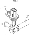
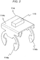
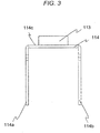
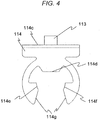
- FIGS. 1 to 4 A first embodiment according to the invention will be described with reference to FIGS. 1 to 4 .
- a position sensor has a target 110 installed in a movable object 112 moving in an axial direction and a magnetic sensor 110 for detecting a movement of the target 110.
- the movable object 112 will be described as a shaft by way of example .
- the magnetic sensor 110 includes, for example, a sensor using a Hall effect element or a sensor using a GMR element.
- the target 110 has a magnet 113 for generating a magnetic flux and a magnetic base 114 for holding the magnet.
- the magnetic base 114 has a structure in which a first fixing portion 114a, a second fixing portion 114b, and a magnet holding portion 114c are integrally formed.
- the first and second fixing portions 114a and 114b are arranged side by side along an axial direction (in other words, movement direction) of the movable object 112.
- the first and second fixing portions 114a and 114b are provided axially outward of an area where the magnet 113 of the magnet holding portion 114c is mounted.
- the first and second fixing portions 114a and 114b have a partially opened ring shape in order to allow installation perpendicular to the axial direction of the movable object 112.
- the first fixing portion is shaped to have first, second, and third contact portions 114d, 114e, and 114f coming into contact with the movable object 112.
- the first to third contact portions are formed such that centers of each contact portion coming into contact with the movable object 112 form an equilateral triangle.
- the first contact portion 114d is formed apart from the opening and has a flat portion.
- the second and third contact portions 114e and 114f are formed in the opening side of the first fixing portion a to match a circumferential shape (side shape) of the movable object 112. If the movable object 112 has a cylindrical shape, the circumferential shape is an arc shape.
- the first fixing portion 114a has a non-contact portion that does not come into contact with the movable object 112 between the first and second contact portions 114d and 114e. Similarly, a non-contact portion that does not come into contact with the movable object 112 is also provided between the first and third fixing portions 114d and 114f. In other words, the first fixing portion 114a has a region having a cross-sectional area smaller than that of each contact portion.
- first fixing portion 114a is tapered such that a shape of its opening 114g is gradually narrowed from the opening end toward the inside.
- the second fixing portion may have the same shape as that of the first fixing portion.
- the target 110 can be installed in the shaft serving as a movable object using the first and second fixing portions 114a and 114b integrated into the magnet holding portion 114c. For this reason, according to this embodiment, the target can be installed in the shaft serving as a sensing target without using a fastening part such as a screw.
- first and second fixing portions 114a and 114b are partially opened ring-shaped fixing portions. Therefore, they can be easily installed from the side direction of the movable object 112.
- the first fixing portion is shaped to fix the movable object in three portions including the first to third contact portions, it is possible to prevent a positional deviation in a rotational direction.
- the center points of each contact portion are formed in an equilateral triangle shape, a stress generated during installation becomes symmetric with respect to a center of the movable object 112 three times, so that a rotational stress is cancelled.
- one of the three contact portions apart from the opening is shaped to have a flat portion, and the opening side matches the circumferential shape of the shaft. For this reason, it is possible to improve insertion easiness (installability) to the shaft and more effectively suppress a positional deviation in the rotational direction using the flat portion.
- a diameter of the shaft may change when the shaft is inserted in the axial direction. In this case, it is difficult to promote insertion of the magnetic base and adherence to the shaft.
- the magnetic base can be inserted from the direction perpendicular to the shaft. Therefore, it is possible to secure adherence or installability between the shaft and the magnetic base. Since the non-contact portion has a cross-sectional area smaller than that of the contact portion, it can be easily deformed. Therefore, it is possible to further improve installability at the time of insertion.
- the second and third installation portions are formed on an arc that matches the circumferential shape of the shaft, this change in the diameter can be absorbed by deformation of the non-contact portion even when the diameter of the shaft changes.
- the second and third fixing portions have an arc shape that matches the circumferential shape of the shaft, it is possible to secure adherence between the shaft and the contact portion even when the diameter changes.
- the opening 114g has a tapered shape, it is possible to prevent a point-to-surface contact in which the tip of the first fixing portion 114a comes into contact with the movable object 112.
- the first fixing portion 114a and the movable object 112 make a surface-to-surface contact, it is possible to disperse a stress applied when the target 110 is inserted into the movable object. Therefore, there is no need to insert the target 110 by applying a force more than necessary.
- first and second fixing portions in the same shape, it is possible to further improve installability.
- the same force is applied to the first and second fixing portions during and after the installation. Therefore, it is possible to prevent a rotational or distortional force from being applied to the target 110 and further improve installability and positional accuracy of the target 110 to the movable object 112.
- the second fixing portion 114b in a shape different from that of the first fixing portion 114a, it is possible to easily recognize the installation direction.
- FIGS. 5 to 10 A second embodiment of the present invention will be described with reference to FIGS. 5 to 10 . Note that like reference numerals denote like elements as in the first embodiment, and they will not be described repeatedly.
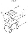
- a position sensor further has a base cover 115 for protecting the magnet 113.
- the base cover 115 is fixed to the magnetic base 114 through welding or the like.
- the base cover 115 has a housing hollow for housing the magnet 113.
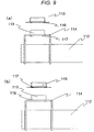
- a protrusion and a hollow for positioning are formed in the magnetic base 114 and the base cover 115 as illustrated in the modification of FIGS. 8 to 10 , positioning is facilitated preferably.
- the positioning protrusion may be provided in the base cover 115, and the positioning hollow may be provided in the magnetic base 114.
- the positioning hollow 117 may be provided in the base cover 115, and the positioning protrusion 116 may be provided in the magnetic base.
- the magnet 113 is protected by the base cover 115. Therefore, it is possible to further improve reliability.
- FIGS. 11 to 16 A third embodiment of the present invention will be described with reference to FIGS. 11 to 16 . Note that like reference numerals denote like elements as in the first and second embodiments, and they will not be described repeatedly.
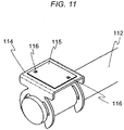
- the third embodiment of the present invention is different from the second embodiment in that the housing hollow for housing the magnet in the second embodiment is formed in the magnetic base side.
- the magnet 113 Since the magnet 113 is housed in the hollow provided in the magnetic base 114, it is possible to hold the magnet 113 without increasing the height of the target 110. Therefore, it is possible to miniaturize the target 110 as a whole.
- the shaft 112 is provided with first and second grooves 112a and 112b along a circumferential direction.
- a truncated portion 112c formed by cutting a part of the side surface is provided on the area including the first and second grooves on the side surface of the shaft 112.
- the target 110 is fixed to the shaft 112 by fitting the first fixing portion 114a into the first groove 112a and fitting the second fixing portion 114b into the second groove 112b.
- first contact portion 114d of the first fixing portion 114a comes into contact with the truncated portion 112c provided in the shaft 112 (in other words, the flat portion).
- the first contact portion 114d comes into contact with the truncated portion 112c as in the first fixing portion 114a.
- first and second fixing portions 114a and 114b having a ring shape By fitting the first and second fixing portions 114a and 114b having a ring shape into the first and second grooves 112a and 112b provided in the shaft 112, it is possible to suppress a positional deviation of the target 110 in the axial direction. In addition, since the target 110 can be installed while being guided by this groove, installability is improved.
- the first contact portion 114d having a flat portion and the truncated portion come into contact with each other, it is possible to suppress a positional deviation in the rotational direction.
- the holding portion of the magnetic base is fixed to the flattened portion of the shaft 112, it is possible to easily recognize a position where the magnet is to be fixed.
- the first contact portion 114d comes into contact with the truncated portion (flat portion) in two positions. Therefore, it is possible to further suppress a positional deviation in the rotational direction.
- the truncated portion 112c is formed in the shaft 112 by way of example in the aforementioned description, alternatively, the truncated portion 112c may be substituted with a notch.
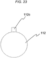
- a hollow 112d may be formed as illustrated in FIGS. 19 and 20 , or a protrusion 112e may be formed as illustrated in FIGS. 21 , 22 , and 23 . In such a configuration, it is possible to obtain the same effects as those of the truncated portion 112c.
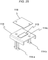
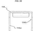
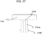
- FIGS. 25 to 35 A fourth embodiment of the present invention will be described with reference to FIGS. 25 to 35 . Note that like reference numerals denote like elements as in the first to third embodiments, and they will not be described repeatedly.
- the first and second fixing portions have shapes different from those of the first to third embodiments.
- the first fixing portion 114a has a pair of plates straightly extending in parallel such that they can be inserted into holes of the movable object 112 to allow fixation.
- tip portions 114h have a hook shape.
- the target 110 can be fixed to the shaft 112.
- the first fixing portion 112a has a base portion 112i having an R-shape which is a relief shape. By virtue of this relief shape, the first fixing portion 112a can be easily deformed when installing the target 110 in the shaft 112. Therefore, installability is improved.
- the second fixing portion 112b has the same shape as that of the first fixing portion.
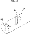
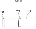
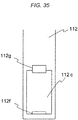
- the shaft 112 where the target 110 is installed is provided with a truncated portion 112c, a first hole 112f, and a second hole g.
- FIGS. 36 to 45 A fifth embodiment of the present invention will be described with reference to FIGS. 36 to 45 . Note that like reference numerals denote like elements as in the first to third embodiments, and they will not be described repeatedly.
- the second fixing portion 112b has a shape different from those of the first to third embodiments.
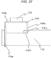
- the second fixing portion 112b is provided with a hollow 114j fitted to the protrusion 112h of the movable object 112. As a result, a movement in a twist direction is restricted. According to this embodiment, it is possible to fix the target 110 to the movable object 112 while simplifying the configuration of the second fixing portion 112b.
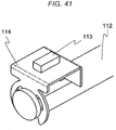
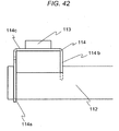
- the second fixing portion 112b is provided with a protrusion 114k fitted to the hollow 112i of the movable object 112 as illustrated in FIGS. 41 to 45 .
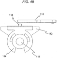
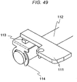
- the target 110 can also be easily installed in a movable object 112 even when the movable object has a cylindrical portion provided with a cavity such as a pulley, and a shaft 1 is inserted into the cylindrical portion so that the cylindrical portion moves along the shaft as illustrated in FIGS. 46 to 48 .
- the target 110 can also be easily installed in a movable object even when the movable object has a cylindrical portion such as a pulley and a shaft is arranged inside the cylindrical portion.
- the target can be easily installed from a direction perpendicular to the axial direction. Therefore, it is possible to improve freedom in installation.
- it is not necessary to form an installation portion for installation on the outside in the axial direction. Therefore, this contributes to miniaturization as a whole.
- the magnetic sensor 111 is arranged perpendicularly to the magnet 113 as illustrated in FIG. 1 .
- the magnetic sensor 111 may be arranged in parallel with the magnet 113 as illustrated in FIGS. 45 to 51 .
Landscapes
- Engineering & Computer Science (AREA)
- General Engineering & Computer Science (AREA)
- Physics & Mathematics (AREA)
- General Physics & Mathematics (AREA)
- Mechanical Engineering (AREA)
- Transmission And Conversion Of Sensor Element Output (AREA)
- Measurement Of Length, Angles, Or The Like Using Electric Or Magnetic Means (AREA)
Abstract
Description
- The present invention relates to a position sensor.
- A structure for installing a magnetic position sensor is discussed in
PTL 1. The magnet installation structure ofPTL 1 has a magnet, a holder, and a shaft. The holder is formed in a partially truncated cylindrical shape. The shaft has a hollow, and the magnet is disposed in the hollow of the shaft, so that the magnet is easily fixed in an accurate position by fitting the holder perpendicularly to the axial direction of the shaft. - PTL 1: Japanese Unexamined Patent Application Publication No.
2005-9996 - However, in the structure for fitting the magnet into the shaft using the holder, the magnet may move perpendicularly to the axial direction of the shaft or in the axial direction of the shaft if a slight gap exists between the magnet and the holder. Therefore, a position between the shaft and the magnet may change disadvantageously.
- In addition, in an axial insertion shape, it is difficult to dispose other structural components in the insertion direction. Therefore, it is difficult to secure freedom in the installation structure.
- In view of the aforementioned problems, an object of the present invention is to provide a position sensor capable of improve installability for installing the magnet in a movable object in the axial direction, such as the shaft.
- In order to achieve the aforementioned object, according to the present invention, there is provided a position sensor including a magnetic sensor and a target installed in a movable object, wherein the target has a magnet and a magnetic base that holds the magnet, and the magnetic base has a magnet holding portion and a fixing portion for fixation to the movable object, the magnet holding portion and the fixing portion being formed integrally.
- According to the present invention, it is possible to easily install the magnet in the movable object that moves in the axial direction, such as the shaft.
-
- [
FIG. 1] FIG. 1 is an installation diagram illustrating a first embodiment. - [
FIG. 2] FIG. 2 is a perspective view illustrating the first embodiment. - [
FIG. 3] FIG. 3 is a side view illustrating the first embodiment. - [
FIG. 4] FIG. 4 is a front view illustrating the first embodiment. - [
FIG. 5] FIG. 5 is a perspective view illustrating a second embodiment. - [
FIG. 6] FIG. 6 is an exploded perspective view illustrating the second embodiment. - [
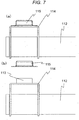
FIG. 7] FIG. 7 is a side view and an exploded side view illustrating the second embodiment. - [
FIG. 8] FIG. 8 is an exploded perspective view illustrating a modification of the second embodiment. - [
FIG. 9] FIG. 9 is an exploded side view illustrating a modification of the second embodiment. - [
FIG. 10] FIG. 10 is a side view illustrating a modification of the second embodiment. - [
FIG. 11] FIG. 11 is a perspective view illustrating a third embodiment. - [
FIG. 12] FIG. 12 is an exploded perspective view illustrating the third embodiment. - [
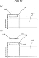
FIG. 13] FIG. 13 is a side view and an exploded side view illustrating the third embodiment. - [
FIG. 14] FIG. 14 is a perspective view illustrating a modification of the third embodiment. - [
FIG. 15] FIG. 15 is an exploded perspective view illustrating a modification of the third embodiment. - [
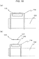
FIG. 16] FIG. 16 is a side view and an exploded side view illustrating a modification of the third embodiment. - [
FIG. 17] FIG. 17 is a front view illustrating a shaft according to the first to third embodiments. - [
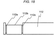
FIG. 18] FIG. 18 is a side view illustrating a shaft according to the first to third embodiments. - [
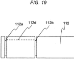
FIG. 19] FIG. 19 is a side view illustrating a shaft according to a modification of the first to third embodiments. - [
FIG. 20] FIG. 20 is a front view illustrating a shaft according to a modification of the first to third embodiments. - [
FIG. 21] FIG. 21 is a top plan view illustrating a shaft according to a modification of the first to third embodiments. - [
FIG. 22] FIG. 22 is a side view illustrating a shaft according to a modification of the first to third embodiments. - [
FIG. 23] FIG. 23 is a front view illustrating a shaft according to a modification of the first to third embodiments. - [
FIG. 24] FIG. 24 is a top plan view illustrating a shaft according to a modification of the first to third embodiments. - [
FIG. 25] FIG. 25 is an exploded perspective view illustrating a fourth embodiment. - [
FIG. 26] FIG. 26 is a side view illustrating a fourth embodiment. - [
FIG. 27] FIG. 27 is a front view illustrating the fourth embodiment. - [
FIG. 28] FIG. 28 is a perspective view for installation according to the fourth embodiment. - [
FIG. 29] FIG. 29 is an exploded perspective view for installation according to the fourth embodiment. - [
FIG. 30] FIG. 30 is an exploded side view and a side view for installation according to the fourth embodiment. - [
FIG. 31] FIG. 31 is a top plan view for installation according to the fourth embodiment. - [
FIG. 32] FIG. 32 is a perspective view illustrating a shaft according to the fourth embodiment. - [
FIG. 33] FIG. 33 is a side view illustrating a shaft according to the fourth embodiment. - [
FIG. 34] FIG. 34 is a front view illustrating a shaft according to the fourth embodiment. - [
FIG. 35] FIG. 35 is a top plan view illustrating a shaft according to the fourth embodiment. - [
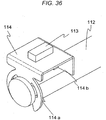
FIG. 36] FIG. 36 is a perspective view for installation according to a fifth embodiment. - [
FIG. 37] FIG. 37 is a side view for installation according to the fifth embodiment. - [
FIG. 38] FIG. 38 is a perspective view illustrating a shaft according to the fifth embodiment. - [
FIG. 39] FIG. 39 is a side view illustrating a shaft according to the fifth embodiment. - [
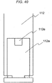
FIG. 40] FIG. 40 is a top plan view illustrating a shaft according to the fifth embodiment. - [
FIG. 41] FIG. 41 is a perspective view for installation according to a sixth embodiment. - [
FIG. 42] FIG. 42 is a side view for installation according to the sixth embodiment. - [
FIG. 43] FIG. 43 is a perspective view illustrating a shaft according to the sixth embodiment. - [
FIG. 44] FIG. 44 is a side view illustrating a shaft according to the sixth embodiment. - [
FIG. 45] FIG. 45 is a top plan view illustrating a shaft according to the sixth embodiment. - [
FIG. 46] FIG. 46 illustrates an example of installing a position sensor according to the invention in a movable object. - [
FIG. 47] FIG. 47 illustrates an example of installing a position sensor according to the invention in a movable object. - [
FIG. 48] FIG. 48 illustrates an example of installing a position sensor according to the invention in a movable object. - [
FIG. 49] FIG. 49 illustrates an example of installing a position sensor according to the invention in a movable object. - [
FIG. 50] FIG. 50 illustrates an example of installing a position sensor according to the invention in a movable object. - [
FIG. 51] FIG. 51 illustrates an example of installing a position sensor according to the invention in a movable object. - A first embodiment according to the invention will be described with reference to
FIGS. 1 to 4 . - A position sensor according to this embodiment has a
target 110 installed in amovable object 112 moving in an axial direction and amagnetic sensor 110 for detecting a movement of thetarget 110. Here, according to this embodiment, themovable object 112 will be described as a shaft by way of example . - The
magnetic sensor 110 includes, for example, a sensor using a Hall effect element or a sensor using a GMR element. - The
target 110 has amagnet 113 for generating a magnetic flux and amagnetic base 114 for holding the magnet. - The
magnetic base 114 has a structure in which afirst fixing portion 114a, asecond fixing portion 114b, and amagnet holding portion 114c are integrally formed. The first andsecond fixing portions movable object 112. The first andsecond fixing portions magnet 113 of themagnet holding portion 114c is mounted. - The first and
second fixing portions movable object 112. - The first fixing portion is shaped to have first, second, and
third contact portions movable object 112. The first to third contact portions are formed such that centers of each contact portion coming into contact with themovable object 112 form an equilateral triangle. - The first contact portion 114d is formed apart from the opening and has a flat portion. The second and
third contact portions movable object 112. If themovable object 112 has a cylindrical shape, the circumferential shape is an arc shape. - The
first fixing portion 114a has a non-contact portion that does not come into contact with themovable object 112 between the first andsecond contact portions 114d and 114e. Similarly, a non-contact portion that does not come into contact with themovable object 112 is also provided between the first andthird fixing portions 114d and 114f. In other words, thefirst fixing portion 114a has a region having a cross-sectional area smaller than that of each contact portion. - In addition, the
first fixing portion 114a is tapered such that a shape of itsopening 114g is gradually narrowed from the opening end toward the inside. - The second fixing portion may have the same shape as that of the first fixing portion.
- The effects of this embodiment will be described.
- The
target 110 can be installed in the shaft serving as a movable object using the first andsecond fixing portions magnet holding portion 114c. For this reason, according to this embodiment, the target can be installed in the shaft serving as a sensing target without using a fastening part such as a screw. - In addition, the first and
second fixing portions movable object 112. - In addition, since the first fixing portion is shaped to fix the movable object in three portions including the first to third contact portions, it is possible to prevent a positional deviation in a rotational direction. In particular, if the center points of each contact portion are formed in an equilateral triangle shape, a stress generated during installation becomes symmetric with respect to a center of the
movable object 112 three times, so that a rotational stress is cancelled. - In addition, one of the three contact portions apart from the opening is shaped to have a flat portion, and the opening side matches the circumferential shape of the shaft. For this reason, it is possible to improve insertion easiness (installability) to the shaft and more effectively suppress a positional deviation in the rotational direction using the flat portion.
- A diameter of the shaft may change when the shaft is inserted in the axial direction. In this case, it is difficult to promote insertion of the magnetic base and adherence to the shaft. However, according to this embodiment, even when the diameter of the shaft changes between a tip portion and a portion where the magnet is to be installed and the portion to be installed, the magnetic base can be inserted from the direction perpendicular to the shaft. Therefore, it is possible to secure adherence or installability between the shaft and the magnetic base. Since the non-contact portion has a cross-sectional area smaller than that of the contact portion, it can be easily deformed. Therefore, it is possible to further improve installability at the time of insertion.
- In addition, since the second and third installation portions are formed on an arc that matches the circumferential shape of the shaft, this change in the diameter can be absorbed by deformation of the non-contact portion even when the diameter of the shaft changes.
- In addition, since the second and third fixing portions have an arc shape that matches the circumferential shape of the shaft, it is possible to secure adherence between the shaft and the contact portion even when the diameter changes.
- In addition, since the
opening 114g has a tapered shape, it is possible to prevent a point-to-surface contact in which the tip of thefirst fixing portion 114a comes into contact with themovable object 112. In addition, since thefirst fixing portion 114a and themovable object 112 make a surface-to-surface contact, it is possible to disperse a stress applied when thetarget 110 is inserted into the movable object. Therefore, there is no need to insert thetarget 110 by applying a force more than necessary. - In addition, by forming the first and second fixing portions in the same shape, it is possible to further improve installability. In addition, since they have the same shape, the same force is applied to the first and second fixing portions during and after the installation. Therefore, it is possible to prevent a rotational or distortional force from being applied to the
target 110 and further improve installability and positional accuracy of thetarget 110 to themovable object 112. Note that, by forming thesecond fixing portion 114b in a shape different from that of thefirst fixing portion 114a, it is possible to easily recognize the installation direction. - A second embodiment of the present invention will be described with reference to
FIGS. 5 to 10 . Note that like reference numerals denote like elements as in the first embodiment, and they will not be described repeatedly. - As illustrated in
FIGS. 5 and7 , a position sensor according to this embodiment further has abase cover 115 for protecting themagnet 113. Thebase cover 115 is fixed to themagnetic base 114 through welding or the like. Thebase cover 115 has a housing hollow for housing themagnet 113. - If a protrusion and a hollow for positioning are formed in the
magnetic base 114 and thebase cover 115 as illustrated in the modification ofFIGS. 8 to 10 , positioning is facilitated preferably. In this case, as illustrated inFIGS. 8a ,9a , and10a , the positioning protrusion may be provided in thebase cover 115, and the positioning hollow may be provided in themagnetic base 114. In addition, as illustrated inFIGS. 8b ,9b , and10b , the positioning hollow 117 may be provided in thebase cover 115, and thepositioning protrusion 116 may be provided in the magnetic base. - According to this embodiment, the
magnet 113 is protected by thebase cover 115. Therefore, it is possible to further improve reliability. - A third embodiment of the present invention will be described with reference to
FIGS. 11 to 16 . Note that like reference numerals denote like elements as in the first and second embodiments, and they will not be described repeatedly. - The third embodiment of the present invention is different from the second embodiment in that the housing hollow for housing the magnet in the second embodiment is formed in the magnetic base side.
- Since the
magnet 113 is housed in the hollow provided in themagnetic base 114, it is possible to hold themagnet 113 without increasing the height of thetarget 110. Therefore, it is possible to miniaturize thetarget 110 as a whole. - Next, a structure of the
movable object 112 for installing the position sensor according to the first to third embodiments will be described with reference toFIGS. 17 to 24 . An exemplary shaft will be described as an example of themovable object 112. - As illustrated in
FIGS. 17 and18 , theshaft 112 is provided with first andsecond grooves truncated portion 112c formed by cutting a part of the side surface is provided on the area including the first and second grooves on the side surface of theshaft 112. - The
target 110 is fixed to theshaft 112 by fitting thefirst fixing portion 114a into thefirst groove 112a and fitting thesecond fixing portion 114b into thesecond groove 112b. - In addition, the first contact portion 114d of the
first fixing portion 114a comes into contact with thetruncated portion 112c provided in the shaft 112 (in other words, the flat portion). - When the
second fixing portion 114b is formed similarly to thefirst fixing portion 114a, the first contact portion 114d comes into contact with thetruncated portion 112c as in thefirst fixing portion 114a. - The effects of the aforementioned structure will be described below.
- By fitting the first and
second fixing portions second grooves shaft 112, it is possible to suppress a positional deviation of thetarget 110 in the axial direction. In addition, since thetarget 110 can be installed while being guided by this groove, installability is improved. - Since the first contact portion 114d having a flat portion and the truncated portion come into contact with each other, it is possible to suppress a positional deviation in the rotational direction.
- In addition, since the holding portion of the magnetic base is fixed to the flattened portion of the
shaft 112, it is possible to easily recognize a position where the magnet is to be fixed. - When the
second fixing portion 114b is formed similarly to thefirst fixing portion 114a, the first contact portion 114d comes into contact with the truncated portion (flat portion) in two positions. Therefore, it is possible to further suppress a positional deviation in the rotational direction. - Although the
truncated portion 112c is formed in theshaft 112 by way of example in the aforementioned description, alternatively, thetruncated portion 112c may be substituted with a notch. A hollow 112d may be formed as illustrated inFIGS. 19 and20 , or aprotrusion 112e may be formed as illustrated inFIGS. 21 ,22 , and23 . In such a configuration, it is possible to obtain the same effects as those of thetruncated portion 112c. - A fourth embodiment of the present invention will be described with reference to
FIGS. 25 to 35 . Note that like reference numerals denote like elements as in the first to third embodiments, and they will not be described repeatedly. - In this embodiment, the first and second fixing portions have shapes different from those of the first to third embodiments.
- The
first fixing portion 114a according to this embodiment has a pair of plates straightly extending in parallel such that they can be inserted into holes of themovable object 112 to allow fixation. In addition,tip portions 114h have a hook shape. By inserting thefirst fixing portion 112a into the hole of theshaft 112 and then hooking the hook shape to theshaft 112, thetarget 110 can be fixed to theshaft 112. In addition, thefirst fixing portion 112a has a base portion 112i having an R-shape which is a relief shape. By virtue of this relief shape, thefirst fixing portion 112a can be easily deformed when installing thetarget 110 in theshaft 112. Therefore, installability is improved. Thesecond fixing portion 112b has the same shape as that of the first fixing portion. - As illustrated in
FIGS. 32 to 35 , theshaft 112 where thetarget 110 is installed is provided with atruncated portion 112c, afirst hole 112f, and a second hole g. By inserting thefirst fixing portion 112a into thefirst hole 112f and inserting thesecond fixing portion 112b into thesecond hole 112g, thetarget 110 is fixed to theshaft 112. - Here, by providing a clearance in the
second hole 112g, it is possible to reduce influence of a dimensional change caused by a solid variation. Therefore, it is possible to further improve installability. - A fifth embodiment of the present invention will be described with reference to
FIGS. 36 to 45 . Note that like reference numerals denote like elements as in the first to third embodiments, and they will not be described repeatedly. - In this embodiment, the
second fixing portion 112b has a shape different from those of the first to third embodiments. - As illustrated in
FIGS. 36 to 40 , thesecond fixing portion 112b is provided with a hollow 114j fitted to the protrusion 112h of themovable object 112. As a result, a movement in a twist direction is restricted. According to this embodiment, it is possible to fix thetarget 110 to themovable object 112 while simplifying the configuration of thesecond fixing portion 112b. - As a modification, the
second fixing portion 112b is provided with a protrusion 114k fitted to the hollow 112i of themovable object 112 as illustrated inFIGS. 41 to 45 . - Next, an exemplary case where the position sensor according the first embodiment is installed in the
movable object 112 will be described as an installation example. - Although the position sensor is installed in the shaft in each embodiment, the
target 110 according to the present invention can also be easily installed in amovable object 112 even when the movable object has a cylindrical portion provided with a cavity such as a pulley, and ashaft 1 is inserted into the cylindrical portion so that the cylindrical portion moves along the shaft as illustrated inFIGS. 46 to 48 . - As an advantage of the fixing portion having a ring shape as described in the first to third and fifth embodiments, the
target 110 can also be easily installed in a movable object even when the movable object has a cylindrical portion such as a pulley and a shaft is arranged inside the cylindrical portion. - According to the first to fifth embodiments of the invention, for example, even when a component that may be an obstacle in insertion of the axial direction such as the
structure 117 is formed in the movable object, the target can be easily installed from a direction perpendicular to the axial direction. Therefore, it is possible to improve freedom in installation. In addition, even when such a structure is provided, it is not necessary to form an installation portion for installation on the outside in the axial direction. Therefore, this contributes to miniaturization as a whole. - The
magnetic sensor 111 is arranged perpendicularly to themagnet 113 as illustrated inFIG. 1 . Alternatively, themagnetic sensor 111 may be arranged in parallel with themagnet 113 as illustrated inFIGS. 45 to 51 . -
- 110 target
- 111 magnetic sensor
- 112 movable object
- 112a first groove
- 112b second groove
- 112c truncated portion
- 112d hollow
- 112e protrusion
- 112f hole
- 112g hole
- 112h protrusion
- 112i hollow
- 113 magnet
- 114 magnetic base
- 114a first fixing portion
- 114b second fixing portion
- 114c magnet holding portion
- 114d first contact portion
- 114e second contact portion
- 114f third contact portion
- 114g opening
- 114h tip portion
- 114i base portion
- 114j hollow
- 114k protrusion
- 115 base cover
- 116 positioning protrusion
- 117 positioning hollow
Claims (19)
- A position sensor comprising a magnetic sensor and a target installed in a movable object,
wherein the target has a magnet and a magnetic base that holds the magnet, and
the magnetic base has a magnet holding portion and a fixing portion for fixation to the movable object, the magnet holding portion and the fixing portion being formed integrally. - The position sensor according to claim 1, wherein the fixing portion has a first fixing portion and a second fixing portion.
- The position sensor according to claim 2, wherein the first fixing portion has a partially opened ring shape.
- The position sensor according to claim 3, wherein the first fixing portion has first, second, and third contact portions coming into contact with the movable object.
- The position sensor according to claim 4, wherein the first contact portion is formed apart from the opening,
the second and third contact portions are formed in the opening side,
the first contact portion is shaped to have a flat portion, and
the second and third contact portions have an arc shape. - The position sensor according to claim 5, wherein the first fixing portion has
a first non-contact portion that does not come into contact with the movable object between the first and second contact portions, and
a second non-contact portion that does not come into contact with the movable object between the first and second contact portions. - The position sensor according to claim 6, wherein an opening of the first fixing portion has a tapered shape gradually narrowing from an opening end to an inner side.
- The position sensor according to any one of claims 4 to 7, wherein the second fixing portion has a shape similar to that of the first fixing portion.
- The position sensor according to any one of claims 4 to 7, wherein the second fixing portion is shaped to have a protrusion fitted into a hollow formed in the movable object or a hollow fitted into a protrusion formed in the movable object.
- The position sensor according to claim 3, wherein the movable object has a groove formed along a circumferential direction, and
the target is fixed to the movable object by fitting the fixing portion into the groove. - The position sensor according to claim 8, wherein the movable object has first and second grooves formed along a circumferential direction,
the first groove has a partially flattened portion,
the target is fixed to the movable object by fitting the first fixing portion into the first groove and fitting the second fixing portion into the second groove, and
the first contact portion comes into contact with the flattened portion. - The position sensor according to claim 8, wherein the movable object has first and second grooves formed along a circumferential direction,
a flattened flat portion is formed between the first and second grooves,
the target is fixed to the movable object by fitting the first fixing portion into the first groove and fitting the second fixing portion into the second groove, and
the magnet holding portion is fixed in a position facing the flat portion. - The position sensor according to any one of claims 1 to 12, further comprising a base cover that covers the magnet,
wherein the magnetic base has a housing hollow formed in the magnet holding portion, and
the magnet is disposed in the hollow. - The position sensor according to any one of claims 1 to 12, further comprising a base cover that covers the magnet,
wherein the base cover is provided with a housing hollow that houses the magnet. - The position sensor according to claim 13 or 14, wherein the magnetic base is provided with a hollow or a protrusion that matches a positioning protrusion or a positioning hollow formed in the base cover.
- The position sensor according to claim 2, wherein the first and second fixing portions have a tip having a hook shape for fixing the target.
- The position sensor according to claim 16, wherein the movable object has a partially flattened portion on its side surface,
the flattened portion is provided with first and second holes,
the target can be fixed to the movable object by inserting the first fixing portion into the first hole, inserting the second fixing portion into the second hole, and hooking the hook shape in the movable object, and
one of the first and second holes is shaped to have a clearance. - A target installed in a movable object moving in an axial direction and provided with a magnet that generates a magnetic force detected by a magnetic sensor,
wherein the target has a magnetic base for holding the magnet, and
the magnetic base has a magnet holding portion and a fixing portion for fixation to the movable object, the magnet holding portion and the fixing portion being formed integrally. - The target according to claim 18, wherein the fixing portion has first and second fixing portions,
the first fixing portion has a partially opened ring shape,
an opening of the first fixing portion has a tapered shape gradually narrowing from an opening end to an inner side,
the first fixing portion has
first, second, and third contact portions coming into contact with the movable object,
a first non-contact portion that does not come into contact with the movable object between the first and second contact portions, and
a second non-contact portion that does not come into contact with the movable object between the first and second contact portions,
the first contact portion is formed apart from the opening,
the second and third contact portions are formed in the opening side,
the first contact portion is shaped to have a flat portion,
the second and third contact portions have an arc shape, and
the second fixing portion has a shape similar to that of the first fixing portion.
Applications Claiming Priority (2)
| Application Number | Priority Date | Filing Date | Title |
|---|---|---|---|
| JP2015169984 | 2015-08-31 | ||
| PCT/JP2016/071955 WO2017038318A1 (en) | 2015-08-31 | 2016-07-27 | Position sensor |
Publications (3)
| Publication Number | Publication Date |
|---|---|
| EP3346239A1 true EP3346239A1 (en) | 2018-07-11 |
| EP3346239A4 EP3346239A4 (en) | 2019-04-03 |
| EP3346239B1 EP3346239B1 (en) | 2020-04-08 |
Family
ID=58187334
Family Applications (1)
| Application Number | Title | Priority Date | Filing Date |
|---|---|---|---|
| EP16841350.8A Active EP3346239B1 (en) | 2015-08-31 | 2016-07-27 | Position sensor |
Country Status (5)
| Country | Link |
|---|---|
| US (1) | US20180202836A1 (en) |
| EP (1) | EP3346239B1 (en) |
| JP (1) | JP6473822B2 (en) |
| CN (1) | CN107923763B (en) |
| WO (1) | WO2017038318A1 (en) |
Families Citing this family (4)
| Publication number | Priority date | Publication date | Assignee | Title |
|---|---|---|---|---|
| JP6696811B2 (en) * | 2016-03-30 | 2020-05-20 | Ntn株式会社 | Sensor target, movable unit including the target, and electric actuator |
| JP6669184B2 (en) * | 2018-03-14 | 2020-03-18 | Tdk株式会社 | Shaft unit, method of manufacturing the same, position detecting device, and magnetic member |
| CN109115105B (en) * | 2018-07-27 | 2020-08-14 | 合肥工业大学 | A device for monitoring the contact state of a shaft retaining ring and a shaft groove |
| US11555719B2 (en) * | 2018-12-12 | 2023-01-17 | Hl Mando Corporation | Actuator assembly having rotary sensor responsive to rotation of magnet |
Family Cites Families (13)
| Publication number | Priority date | Publication date | Assignee | Title |
|---|---|---|---|---|
| US5789917A (en) * | 1990-12-05 | 1998-08-04 | Moving Magnet Technologie Sa | Magnetic position sensor with hall probe formed in an air gap of a stator |
| US6124710A (en) * | 1998-11-13 | 2000-09-26 | Cts Corporation | Rotary magnetic encoder using hall effect for detecting revolution of a shaft |
| JP3596667B2 (en) * | 2000-01-26 | 2004-12-02 | 株式会社デンソー | Rotation angle detector |
| JP4590785B2 (en) * | 2001-06-19 | 2010-12-01 | パナソニック株式会社 | Non-contact position sensor |
| JP4007313B2 (en) * | 2003-01-22 | 2007-11-14 | 株式会社村田製作所 | Angle sensor |
| JP4201654B2 (en) * | 2003-06-18 | 2008-12-24 | 栄通信工業株式会社 | Magnetic potentiometer |
| JP4578159B2 (en) * | 2004-06-22 | 2010-11-10 | アルプス電気株式会社 | Position sensor |
| JP5051918B2 (en) * | 2006-04-27 | 2012-10-17 | 旭化成エレクトロニクス株式会社 | Position detection apparatus and position detection method |
| WO2010068241A1 (en) * | 2008-11-26 | 2010-06-17 | Cts Corporation | Linear position sensor with anti-rotation device |
| JP2014052281A (en) * | 2012-09-07 | 2014-03-20 | Tokai Rika Co Ltd | Biaxial position sensor and shift position sensor including the same |
| US9851220B2 (en) * | 2012-11-12 | 2017-12-26 | Nissan Motor Co., Ltd. | Rotational position sensor structure for an intake manifold |
| JP2015125103A (en) * | 2013-12-27 | 2015-07-06 | 日本精機株式会社 | Stroke sensor |
| JP2016099187A (en) * | 2014-11-20 | 2016-05-30 | アイシン精機株式会社 | Rotation angle detector |
-
2016
- 2016-07-27 EP EP16841350.8A patent/EP3346239B1/en active Active
- 2016-07-27 CN CN201680047138.4A patent/CN107923763B/en active Active
- 2016-07-27 JP JP2017537659A patent/JP6473822B2/en active Active
- 2016-07-27 US US15/743,957 patent/US20180202836A1/en not_active Abandoned
- 2016-07-27 WO PCT/JP2016/071955 patent/WO2017038318A1/en not_active Ceased
Also Published As
| Publication number | Publication date |
|---|---|
| CN107923763A (en) | 2018-04-17 |
| JPWO2017038318A1 (en) | 2018-03-01 |
| US20180202836A1 (en) | 2018-07-19 |
| WO2017038318A1 (en) | 2017-03-09 |
| CN107923763B (en) | 2020-11-06 |
| EP3346239B1 (en) | 2020-04-08 |
| EP3346239A4 (en) | 2019-04-03 |
| JP6473822B2 (en) | 2019-02-20 |
Similar Documents
| Publication | Publication Date | Title |
|---|---|---|
| EP3346239B1 (en) | Position sensor | |
| US10060808B2 (en) | Torque detector | |
| US8914952B2 (en) | Clip | |
| KR102468664B1 (en) | tilting pad bearing | |
| EP2657545B1 (en) | Two-piece clip | |
| US10746218B2 (en) | Fastener for securing a panel on a support | |
| US9341210B2 (en) | Fastener | |
| US20050091802A1 (en) | Clip | |
| CN115112158A (en) | Sensor housing | |
| CN104838153B (en) | Magnet holding member for gear mechanism position sensor arrangement and locking sleeve | |
| CN110770474B (en) | Ball screw | |
| CN104685227A (en) | Fixture | |
| KR20110048026A (en) | Clip Attachment Structure of Writing Instruments | |
| JP2015104236A (en) | Resolver | |
| US9696334B2 (en) | Wheel speed sensor | |
| CN105981248B (en) | Annex arrangement on flange member | |
| CN111692184B (en) | Tolerance compensator | |
| JP2018036206A (en) | Sensor device | |
| US11199213B2 (en) | Mounting structure and clip | |
| JP2019056472A (en) | solenoid valve | |
| KR200476312Y1 (en) | Anti-rotation structure of steering column | |
| KR20160135824A (en) | Sensor-magnet assembly | |
| EP3640579A1 (en) | Rotation detection device | |
| US20250248491A1 (en) | Slider | |
| JP5856857B2 (en) | Objective lens adapter mounting guide |
Legal Events
| Date | Code | Title | Description |
|---|---|---|---|
| STAA | Information on the status of an ep patent application or granted ep patent |
Free format text: STATUS: THE INTERNATIONAL PUBLICATION HAS BEEN MADE |
|
| PUAI | Public reference made under article 153(3) epc to a published international application that has entered the european phase |
Free format text: ORIGINAL CODE: 0009012 |
|
| STAA | Information on the status of an ep patent application or granted ep patent |
Free format text: STATUS: REQUEST FOR EXAMINATION WAS MADE |
|
| 17P | Request for examination filed |
Effective date: 20171128 |
|
| AK | Designated contracting states |
Kind code of ref document: A1 Designated state(s): AL AT BE BG CH CY CZ DE DK EE ES FI FR GB GR HR HU IE IS IT LI LT LU LV MC MK MT NL NO PL PT RO RS SE SI SK SM TR |
|
| AX | Request for extension of the european patent |
Extension state: BA ME |
|
| DAV | Request for validation of the european patent (deleted) | ||
| DAX | Request for extension of the european patent (deleted) | ||
| A4 | Supplementary search report drawn up and despatched |
Effective date: 20190306 |
|
| RIC1 | Information provided on ipc code assigned before grant |
Ipc: F16B 21/18 20060101ALI20190228BHEP Ipc: G01D 5/16 20060101ALI20190228BHEP Ipc: G01D 5/12 20060101AFI20190228BHEP Ipc: G01D 5/14 20060101ALI20190228BHEP Ipc: G01D 11/24 20060101ALI20190228BHEP |
|
| GRAP | Despatch of communication of intention to grant a patent |
Free format text: ORIGINAL CODE: EPIDOSNIGR1 |
|
| STAA | Information on the status of an ep patent application or granted ep patent |
Free format text: STATUS: GRANT OF PATENT IS INTENDED |
|
| RIC1 | Information provided on ipc code assigned before grant |
Ipc: G01D 5/16 20060101ALI20191129BHEP Ipc: G01D 11/24 20060101ALI20191129BHEP Ipc: F16B 21/18 20060101ALI20191129BHEP Ipc: G01D 5/12 20060101AFI20191129BHEP Ipc: G01D 5/14 20060101ALI20191129BHEP |
|
| INTG | Intention to grant announced |
Effective date: 20200107 |
|
| GRAS | Grant fee paid |
Free format text: ORIGINAL CODE: EPIDOSNIGR3 |
|
| GRAA | (expected) grant |
Free format text: ORIGINAL CODE: 0009210 |
|
| STAA | Information on the status of an ep patent application or granted ep patent |
Free format text: STATUS: THE PATENT HAS BEEN GRANTED |
|
| AK | Designated contracting states |
Kind code of ref document: B1 Designated state(s): AL AT BE BG CH CY CZ DE DK EE ES FI FR GB GR HR HU IE IS IT LI LT LU LV MC MK MT NL NO PL PT RO RS SE SI SK SM TR |
|
| REG | Reference to a national code |
Ref country code: CH Ref legal event code: EP Ref country code: AT Ref legal event code: REF Ref document number: 1254996 Country of ref document: AT Kind code of ref document: T Effective date: 20200415 |
|
| REG | Reference to a national code |
Ref country code: DE Ref legal event code: R096 Ref document number: 602016033816 Country of ref document: DE |
|
| REG | Reference to a national code |
Ref country code: IE Ref legal event code: FG4D |
|
| REG | Reference to a national code |
Ref country code: NL Ref legal event code: MP Effective date: 20200408 |
|
| REG | Reference to a national code |
Ref country code: LT Ref legal event code: MG4D |
|
| PG25 | Lapsed in a contracting state [announced via postgrant information from national office to epo] |
Ref country code: IS Free format text: LAPSE BECAUSE OF FAILURE TO SUBMIT A TRANSLATION OF THE DESCRIPTION OR TO PAY THE FEE WITHIN THE PRESCRIBED TIME-LIMIT Effective date: 20200808 Ref country code: NO Free format text: LAPSE BECAUSE OF FAILURE TO SUBMIT A TRANSLATION OF THE DESCRIPTION OR TO PAY THE FEE WITHIN THE PRESCRIBED TIME-LIMIT Effective date: 20200708 Ref country code: SE Free format text: LAPSE BECAUSE OF FAILURE TO SUBMIT A TRANSLATION OF THE DESCRIPTION OR TO PAY THE FEE WITHIN THE PRESCRIBED TIME-LIMIT Effective date: 20200408 Ref country code: GR Free format text: LAPSE BECAUSE OF FAILURE TO SUBMIT A TRANSLATION OF THE DESCRIPTION OR TO PAY THE FEE WITHIN THE PRESCRIBED TIME-LIMIT Effective date: 20200709 Ref country code: FI Free format text: LAPSE BECAUSE OF FAILURE TO SUBMIT A TRANSLATION OF THE DESCRIPTION OR TO PAY THE FEE WITHIN THE PRESCRIBED TIME-LIMIT Effective date: 20200408 Ref country code: LT Free format text: LAPSE BECAUSE OF FAILURE TO SUBMIT A TRANSLATION OF THE DESCRIPTION OR TO PAY THE FEE WITHIN THE PRESCRIBED TIME-LIMIT Effective date: 20200408 Ref country code: PT Free format text: LAPSE BECAUSE OF FAILURE TO SUBMIT A TRANSLATION OF THE DESCRIPTION OR TO PAY THE FEE WITHIN THE PRESCRIBED TIME-LIMIT Effective date: 20200817 Ref country code: NL Free format text: LAPSE BECAUSE OF FAILURE TO SUBMIT A TRANSLATION OF THE DESCRIPTION OR TO PAY THE FEE WITHIN THE PRESCRIBED TIME-LIMIT Effective date: 20200408 |
|
| REG | Reference to a national code |
Ref country code: AT Ref legal event code: MK05 Ref document number: 1254996 Country of ref document: AT Kind code of ref document: T Effective date: 20200408 |
|
| PG25 | Lapsed in a contracting state [announced via postgrant information from national office to epo] |
Ref country code: LV Free format text: LAPSE BECAUSE OF FAILURE TO SUBMIT A TRANSLATION OF THE DESCRIPTION OR TO PAY THE FEE WITHIN THE PRESCRIBED TIME-LIMIT Effective date: 20200408 Ref country code: BG Free format text: LAPSE BECAUSE OF FAILURE TO SUBMIT A TRANSLATION OF THE DESCRIPTION OR TO PAY THE FEE WITHIN THE PRESCRIBED TIME-LIMIT Effective date: 20200708 Ref country code: HR Free format text: LAPSE BECAUSE OF FAILURE TO SUBMIT A TRANSLATION OF THE DESCRIPTION OR TO PAY THE FEE WITHIN THE PRESCRIBED TIME-LIMIT Effective date: 20200408 Ref country code: RS Free format text: LAPSE BECAUSE OF FAILURE TO SUBMIT A TRANSLATION OF THE DESCRIPTION OR TO PAY THE FEE WITHIN THE PRESCRIBED TIME-LIMIT Effective date: 20200408 |
|
| PG25 | Lapsed in a contracting state [announced via postgrant information from national office to epo] |
Ref country code: AL Free format text: LAPSE BECAUSE OF FAILURE TO SUBMIT A TRANSLATION OF THE DESCRIPTION OR TO PAY THE FEE WITHIN THE PRESCRIBED TIME-LIMIT Effective date: 20200408 |
|
| REG | Reference to a national code |
Ref country code: DE Ref legal event code: R097 Ref document number: 602016033816 Country of ref document: DE |
|
| PG25 | Lapsed in a contracting state [announced via postgrant information from national office to epo] |
Ref country code: SM Free format text: LAPSE BECAUSE OF FAILURE TO SUBMIT A TRANSLATION OF THE DESCRIPTION OR TO PAY THE FEE WITHIN THE PRESCRIBED TIME-LIMIT Effective date: 20200408 Ref country code: IT Free format text: LAPSE BECAUSE OF FAILURE TO SUBMIT A TRANSLATION OF THE DESCRIPTION OR TO PAY THE FEE WITHIN THE PRESCRIBED TIME-LIMIT Effective date: 20200408 Ref country code: EE Free format text: LAPSE BECAUSE OF FAILURE TO SUBMIT A TRANSLATION OF THE DESCRIPTION OR TO PAY THE FEE WITHIN THE PRESCRIBED TIME-LIMIT Effective date: 20200408 Ref country code: DK Free format text: LAPSE BECAUSE OF FAILURE TO SUBMIT A TRANSLATION OF THE DESCRIPTION OR TO PAY THE FEE WITHIN THE PRESCRIBED TIME-LIMIT Effective date: 20200408 Ref country code: ES Free format text: LAPSE BECAUSE OF FAILURE TO SUBMIT A TRANSLATION OF THE DESCRIPTION OR TO PAY THE FEE WITHIN THE PRESCRIBED TIME-LIMIT Effective date: 20200408 Ref country code: AT Free format text: LAPSE BECAUSE OF FAILURE TO SUBMIT A TRANSLATION OF THE DESCRIPTION OR TO PAY THE FEE WITHIN THE PRESCRIBED TIME-LIMIT Effective date: 20200408 Ref country code: RO Free format text: LAPSE BECAUSE OF FAILURE TO SUBMIT A TRANSLATION OF THE DESCRIPTION OR TO PAY THE FEE WITHIN THE PRESCRIBED TIME-LIMIT Effective date: 20200408 Ref country code: CZ Free format text: LAPSE BECAUSE OF FAILURE TO SUBMIT A TRANSLATION OF THE DESCRIPTION OR TO PAY THE FEE WITHIN THE PRESCRIBED TIME-LIMIT Effective date: 20200408 |
|
| PLBE | No opposition filed within time limit |
Free format text: ORIGINAL CODE: 0009261 |
|
| STAA | Information on the status of an ep patent application or granted ep patent |
Free format text: STATUS: NO OPPOSITION FILED WITHIN TIME LIMIT |
|
| PG25 | Lapsed in a contracting state [announced via postgrant information from national office to epo] |
Ref country code: PL Free format text: LAPSE BECAUSE OF FAILURE TO SUBMIT A TRANSLATION OF THE DESCRIPTION OR TO PAY THE FEE WITHIN THE PRESCRIBED TIME-LIMIT Effective date: 20200408 Ref country code: MC Free format text: LAPSE BECAUSE OF FAILURE TO SUBMIT A TRANSLATION OF THE DESCRIPTION OR TO PAY THE FEE WITHIN THE PRESCRIBED TIME-LIMIT Effective date: 20200408 Ref country code: SK Free format text: LAPSE BECAUSE OF FAILURE TO SUBMIT A TRANSLATION OF THE DESCRIPTION OR TO PAY THE FEE WITHIN THE PRESCRIBED TIME-LIMIT Effective date: 20200408 |
|
| REG | Reference to a national code |
Ref country code: CH Ref legal event code: PL |
|
| 26N | No opposition filed |
Effective date: 20210112 |
|
| REG | Reference to a national code |
Ref country code: DE Ref legal event code: R082 Ref document number: 602016033816 Country of ref document: DE Representative=s name: STREHL SCHUEBEL-HOPF & PARTNER MBB PATENTANWAE, DE Ref country code: DE Ref legal event code: R081 Ref document number: 602016033816 Country of ref document: DE Owner name: HITACHI ASTEMO, LTD., HITACHINAKA-SHI, JP Free format text: FORMER OWNER: HITACHI AUTOMOTIVE SYSTEMS, LTD., HITACHINAKA-SHI, IBARAKI, JP |
|
| GBPC | Gb: european patent ceased through non-payment of renewal fee |
Effective date: 20200727 |
|
| REG | Reference to a national code |
Ref country code: BE Ref legal event code: MM Effective date: 20200731 |
|
| PG25 | Lapsed in a contracting state [announced via postgrant information from national office to epo] |
Ref country code: CH Free format text: LAPSE BECAUSE OF NON-PAYMENT OF DUE FEES Effective date: 20200731 Ref country code: LU Free format text: LAPSE BECAUSE OF NON-PAYMENT OF DUE FEES Effective date: 20200727 Ref country code: LI Free format text: LAPSE BECAUSE OF NON-PAYMENT OF DUE FEES Effective date: 20200731 Ref country code: FR Free format text: LAPSE BECAUSE OF NON-PAYMENT OF DUE FEES Effective date: 20200731 Ref country code: GB Free format text: LAPSE BECAUSE OF NON-PAYMENT OF DUE FEES Effective date: 20200727 |
|
| PG25 | Lapsed in a contracting state [announced via postgrant information from national office to epo] |
Ref country code: BE Free format text: LAPSE BECAUSE OF NON-PAYMENT OF DUE FEES Effective date: 20200731 Ref country code: SI Free format text: LAPSE BECAUSE OF FAILURE TO SUBMIT A TRANSLATION OF THE DESCRIPTION OR TO PAY THE FEE WITHIN THE PRESCRIBED TIME-LIMIT Effective date: 20200408 |
|
| PG25 | Lapsed in a contracting state [announced via postgrant information from national office to epo] |
Ref country code: IE Free format text: LAPSE BECAUSE OF NON-PAYMENT OF DUE FEES Effective date: 20200727 |
|
| PG25 | Lapsed in a contracting state [announced via postgrant information from national office to epo] |
Ref country code: TR Free format text: LAPSE BECAUSE OF FAILURE TO SUBMIT A TRANSLATION OF THE DESCRIPTION OR TO PAY THE FEE WITHIN THE PRESCRIBED TIME-LIMIT Effective date: 20200408 Ref country code: MT Free format text: LAPSE BECAUSE OF FAILURE TO SUBMIT A TRANSLATION OF THE DESCRIPTION OR TO PAY THE FEE WITHIN THE PRESCRIBED TIME-LIMIT Effective date: 20200408 Ref country code: CY Free format text: LAPSE BECAUSE OF FAILURE TO SUBMIT A TRANSLATION OF THE DESCRIPTION OR TO PAY THE FEE WITHIN THE PRESCRIBED TIME-LIMIT Effective date: 20200408 |
|
| PG25 | Lapsed in a contracting state [announced via postgrant information from national office to epo] |
Ref country code: MK Free format text: LAPSE BECAUSE OF FAILURE TO SUBMIT A TRANSLATION OF THE DESCRIPTION OR TO PAY THE FEE WITHIN THE PRESCRIBED TIME-LIMIT Effective date: 20200408 |
|
| PGFP | Annual fee paid to national office [announced via postgrant information from national office to epo] |
Ref country code: DE Payment date: 20250604 Year of fee payment: 10 |