EP3346220A1 - Heat pipe with non-uniform cross-section - Google Patents
Heat pipe with non-uniform cross-section Download PDFInfo
- Publication number
- EP3346220A1 EP3346220A1 EP17206431.3A EP17206431A EP3346220A1 EP 3346220 A1 EP3346220 A1 EP 3346220A1 EP 17206431 A EP17206431 A EP 17206431A EP 3346220 A1 EP3346220 A1 EP 3346220A1
- Authority
- EP
- European Patent Office
- Prior art keywords
- heat pipe
- protrusions
- tube
- heat
- length
- Prior art date
- Legal status (The legal status is an assumption and is not a legal conclusion. Google has not performed a legal analysis and makes no representation as to the accuracy of the status listed.)
- Granted
Links
Images




Classifications
-
- F—MECHANICAL ENGINEERING; LIGHTING; HEATING; WEAPONS; BLASTING
- F28—HEAT EXCHANGE IN GENERAL
- F28D—HEAT-EXCHANGE APPARATUS, NOT PROVIDED FOR IN ANOTHER SUBCLASS, IN WHICH THE HEAT-EXCHANGE MEDIA DO NOT COME INTO DIRECT CONTACT
- F28D15/00—Heat-exchange apparatus with the intermediate heat-transfer medium in closed tubes passing into or through the conduit walls ; Heat-exchange apparatus employing intermediate heat-transfer medium or bodies
- F28D15/02—Heat-exchange apparatus with the intermediate heat-transfer medium in closed tubes passing into or through the conduit walls ; Heat-exchange apparatus employing intermediate heat-transfer medium or bodies in which the medium condenses and evaporates, e.g. heat pipes
- F28D15/0266—Heat-exchange apparatus with the intermediate heat-transfer medium in closed tubes passing into or through the conduit walls ; Heat-exchange apparatus employing intermediate heat-transfer medium or bodies in which the medium condenses and evaporates, e.g. heat pipes with separate evaporating and condensing chambers connected by at least one conduit; Loop-type heat pipes; with multiple or common evaporating or condensing chambers
-
- F—MECHANICAL ENGINEERING; LIGHTING; HEATING; WEAPONS; BLASTING
- F28—HEAT EXCHANGE IN GENERAL
- F28D—HEAT-EXCHANGE APPARATUS, NOT PROVIDED FOR IN ANOTHER SUBCLASS, IN WHICH THE HEAT-EXCHANGE MEDIA DO NOT COME INTO DIRECT CONTACT
- F28D15/00—Heat-exchange apparatus with the intermediate heat-transfer medium in closed tubes passing into or through the conduit walls ; Heat-exchange apparatus employing intermediate heat-transfer medium or bodies
- F28D15/02—Heat-exchange apparatus with the intermediate heat-transfer medium in closed tubes passing into or through the conduit walls ; Heat-exchange apparatus employing intermediate heat-transfer medium or bodies in which the medium condenses and evaporates, e.g. heat pipes
- F28D15/04—Heat-exchange apparatus with the intermediate heat-transfer medium in closed tubes passing into or through the conduit walls ; Heat-exchange apparatus employing intermediate heat-transfer medium or bodies in which the medium condenses and evaporates, e.g. heat pipes with tubes having a capillary structure
-
- B—PERFORMING OPERATIONS; TRANSPORTING
- B33—ADDITIVE MANUFACTURING TECHNOLOGY
- B33Y—ADDITIVE MANUFACTURING, i.e. MANUFACTURING OF THREE-DIMENSIONAL [3D] OBJECTS BY ADDITIVE DEPOSITION, ADDITIVE AGGLOMERATION OR ADDITIVE LAYERING, e.g. BY 3D PRINTING, STEREOLITHOGRAPHY OR SELECTIVE LASER SINTERING
- B33Y80/00—Products made by additive manufacturing
-
- F—MECHANICAL ENGINEERING; LIGHTING; HEATING; WEAPONS; BLASTING
- F28—HEAT EXCHANGE IN GENERAL
- F28D—HEAT-EXCHANGE APPARATUS, NOT PROVIDED FOR IN ANOTHER SUBCLASS, IN WHICH THE HEAT-EXCHANGE MEDIA DO NOT COME INTO DIRECT CONTACT
- F28D15/00—Heat-exchange apparatus with the intermediate heat-transfer medium in closed tubes passing into or through the conduit walls ; Heat-exchange apparatus employing intermediate heat-transfer medium or bodies
- F28D15/02—Heat-exchange apparatus with the intermediate heat-transfer medium in closed tubes passing into or through the conduit walls ; Heat-exchange apparatus employing intermediate heat-transfer medium or bodies in which the medium condenses and evaporates, e.g. heat pipes
- F28D15/0233—Heat-exchange apparatus with the intermediate heat-transfer medium in closed tubes passing into or through the conduit walls ; Heat-exchange apparatus employing intermediate heat-transfer medium or bodies in which the medium condenses and evaporates, e.g. heat pipes the conduits having a particular shape, e.g. non-circular cross-section, annular
-
- F—MECHANICAL ENGINEERING; LIGHTING; HEATING; WEAPONS; BLASTING
- F28—HEAT EXCHANGE IN GENERAL
- F28D—HEAT-EXCHANGE APPARATUS, NOT PROVIDED FOR IN ANOTHER SUBCLASS, IN WHICH THE HEAT-EXCHANGE MEDIA DO NOT COME INTO DIRECT CONTACT
- F28D15/00—Heat-exchange apparatus with the intermediate heat-transfer medium in closed tubes passing into or through the conduit walls ; Heat-exchange apparatus employing intermediate heat-transfer medium or bodies
- F28D15/02—Heat-exchange apparatus with the intermediate heat-transfer medium in closed tubes passing into or through the conduit walls ; Heat-exchange apparatus employing intermediate heat-transfer medium or bodies in which the medium condenses and evaporates, e.g. heat pipes
- F28D15/0275—Arrangements for coupling heat-pipes together or with other structures, e.g. with base blocks; Heat pipe cores
-
- F—MECHANICAL ENGINEERING; LIGHTING; HEATING; WEAPONS; BLASTING
- F28—HEAT EXCHANGE IN GENERAL
- F28D—HEAT-EXCHANGE APPARATUS, NOT PROVIDED FOR IN ANOTHER SUBCLASS, IN WHICH THE HEAT-EXCHANGE MEDIA DO NOT COME INTO DIRECT CONTACT
- F28D15/00—Heat-exchange apparatus with the intermediate heat-transfer medium in closed tubes passing into or through the conduit walls ; Heat-exchange apparatus employing intermediate heat-transfer medium or bodies
- F28D15/02—Heat-exchange apparatus with the intermediate heat-transfer medium in closed tubes passing into or through the conduit walls ; Heat-exchange apparatus employing intermediate heat-transfer medium or bodies in which the medium condenses and evaporates, e.g. heat pipes
- F28D15/04—Heat-exchange apparatus with the intermediate heat-transfer medium in closed tubes passing into or through the conduit walls ; Heat-exchange apparatus employing intermediate heat-transfer medium or bodies in which the medium condenses and evaporates, e.g. heat pipes with tubes having a capillary structure
- F28D15/046—Heat-exchange apparatus with the intermediate heat-transfer medium in closed tubes passing into or through the conduit walls ; Heat-exchange apparatus employing intermediate heat-transfer medium or bodies in which the medium condenses and evaporates, e.g. heat pipes with tubes having a capillary structure characterised by the material or the construction of the capillary structure
-
- F—MECHANICAL ENGINEERING; LIGHTING; HEATING; WEAPONS; BLASTING
- F28—HEAT EXCHANGE IN GENERAL
- F28F—DETAILS OF HEAT-EXCHANGE AND HEAT-TRANSFER APPARATUS, OF GENERAL APPLICATION
- F28F1/00—Tubular elements; Assemblies of tubular elements
- F28F1/006—Tubular elements; Assemblies of tubular elements with variable shape, e.g. with modified tube ends, with different geometrical features
-
- F—MECHANICAL ENGINEERING; LIGHTING; HEATING; WEAPONS; BLASTING
- F28—HEAT EXCHANGE IN GENERAL
- F28F—DETAILS OF HEAT-EXCHANGE AND HEAT-TRANSFER APPARATUS, OF GENERAL APPLICATION
- F28F1/00—Tubular elements; Assemblies of tubular elements
- F28F1/10—Tubular elements and assemblies thereof with means for increasing heat-transfer area, e.g. with fins, with projections, with recesses
- F28F1/40—Tubular elements and assemblies thereof with means for increasing heat-transfer area, e.g. with fins, with projections, with recesses the means being only inside the tubular element
-
- F—MECHANICAL ENGINEERING; LIGHTING; HEATING; WEAPONS; BLASTING
- F28—HEAT EXCHANGE IN GENERAL
- F28F—DETAILS OF HEAT-EXCHANGE AND HEAT-TRANSFER APPARATUS, OF GENERAL APPLICATION
- F28F13/00—Arrangements for modifying heat-transfer, e.g. increasing, decreasing
- F28F13/06—Arrangements for modifying heat-transfer, e.g. increasing, decreasing by affecting the pattern of flow of the heat-exchange media
- F28F13/08—Arrangements for modifying heat-transfer, e.g. increasing, decreasing by affecting the pattern of flow of the heat-exchange media by varying the cross-section of the flow channels
-
- B—PERFORMING OPERATIONS; TRANSPORTING
- B23—MACHINE TOOLS; METAL-WORKING NOT OTHERWISE PROVIDED FOR
- B23P—METAL-WORKING NOT OTHERWISE PROVIDED FOR; COMBINED OPERATIONS; UNIVERSAL MACHINE TOOLS
- B23P15/00—Making specific metal objects by operations not covered by a single other subclass or a group in this subclass
- B23P15/26—Making specific metal objects by operations not covered by a single other subclass or a group in this subclass heat exchangers or the like
-
- B—PERFORMING OPERATIONS; TRANSPORTING
- B23—MACHINE TOOLS; METAL-WORKING NOT OTHERWISE PROVIDED FOR
- B23P—METAL-WORKING NOT OTHERWISE PROVIDED FOR; COMBINED OPERATIONS; UNIVERSAL MACHINE TOOLS
- B23P2700/00—Indexing scheme relating to the articles being treated, e.g. manufactured, repaired, assembled, connected or other operations covered in the subgroups
- B23P2700/09—Heat pipes
-
- F—MECHANICAL ENGINEERING; LIGHTING; HEATING; WEAPONS; BLASTING
- F28—HEAT EXCHANGE IN GENERAL
- F28D—HEAT-EXCHANGE APPARATUS, NOT PROVIDED FOR IN ANOTHER SUBCLASS, IN WHICH THE HEAT-EXCHANGE MEDIA DO NOT COME INTO DIRECT CONTACT
- F28D21/00—Heat-exchange apparatus not covered by any of the groups F28D1/00 - F28D20/00
- F28D2021/0019—Other heat exchangers for particular applications; Heat exchange systems not otherwise provided for
- F28D2021/0021—Other heat exchangers for particular applications; Heat exchange systems not otherwise provided for for aircrafts or cosmonautics
-
- F—MECHANICAL ENGINEERING; LIGHTING; HEATING; WEAPONS; BLASTING
- F28—HEAT EXCHANGE IN GENERAL
- F28F—DETAILS OF HEAT-EXCHANGE AND HEAT-TRANSFER APPARATUS, OF GENERAL APPLICATION
- F28F2215/00—Fins
- F28F2215/04—Assemblies of fins having different features, e.g. with different fin densities
Definitions
- the present disclosure relates generally to heat pipes, and more specifically, to heat pipes with a non-uniform cross-section. Still more particularly, the present disclosure relates to heat pipes with protrusions having at least one of a tailored spacing, size, or shape.
- a heat pipe transfers heat between a heat sink and a heat source.
- a liquid within the heat pipe vaporizes due to heat from the heat source.
- the vapor travels to the heat sink and condenses into a liquid.
- the condensed liquid travels back to the heat source through grooves formed by protrusions within the heat pipe.
- Today's communication satellites include more than 100 heat pipes per spacecraft. Almost all of these heat pipes are aluminum and ammonia heat pipes. Conventionally, the aluminum bodies of the heat pipes are made by extrusion processes. Extruded structures have a uniform cross-section throughout the pipe length.
- Extrusion shapes are designed to include internal capillary grooves, an external wall or tube, and in some cases, mounting flanges.
- the mounting flanges are selectively located for source and sink locations.
- the mounting flanges are machined following extrusion. By machining the mounting flanges, welds or other joints are not present between the mounting flanges and the external wall. However, the machining process adds additional manufacturing steps and may add undesirable amounts of manufacturing time.
- heat pipes may remain in substantially straight shapes. However, a significant subset of heat pipes is bent to accommodate source and sink locations.
- Some of the heat pipes are bent in a planar geometry. However, the most challenging heat pipes are bent into three-dimensional shapes. In some cases, between three and ten bends are needed to accommodate the geometry. Complex three-dimensional geometries occupy a significant volume and can be hard to integrate.
- the length of the heat pipes is increased to accommodate the complex three-dimensional geometry. Increasing the length of a heat pipe decreases the amount of heat the heat pipe is capable of transferring. Increasing the length of a heat pipe also increases the weight of the heat pipe.
- a heat pipe comprising a tube and protrusions.
- the tube has an internal surface, an external surface, and a length running from a first end to a second end.
- the protrusions extend along the internal surface in a direction of the length of the tube. At least one of a spacing, size, or shape of the protrusions changes between the first end of the tube and the second end of the tube.
- the tube and the protrusions are monolithic.
- a heat pipe in another illustrative example, comprises a tube and protrusions.
- the tube has an internal surface, an external surface, and a length running from a first end to a second end.
- the protrusions are on the internal surface.
- a first cross-section of the protrusions at a first location of the length of the tube is different from a second cross-section of the protrusions at a second location of the length of the tube.
- the tube and the protrusions are monolithic.
- a method of manufacturing a heat pipe is presented.
- Material is laid down using additive manufacturing to form a heat pipe comprising a tube and protrusions.
- the tube has an internal surface, an external surface, and a length running from a first end to a second end.
- the protrusions are on the internal surface.
- a first cross-section of the protrusions at a first location of the length of the tube is different from a second cross-section of the protrusions at a second location of the length of the tube.
- the heat pipe is hot isotropic pressed to reduce porosity.
- the heat pipe is heat treated to increase strength.
- the different illustrative examples recognize and take into account one or more different considerations. For example, the illustrative examples recognize and take into account that extrusion creates uniform cross-sections within manufacturing tolerances.
- the illustrative examples recognize and take into account that the heat transport capacity of a heat pipe is affected by the length of the heat pipe and the design of the grooves of the heat pipe.
- the illustrative examples recognize and take into account that available pressure head may be described as ⁇ P c ⁇ ⁇ P g + ⁇ P ct ⁇ ⁇ P 1 + ⁇ P v where ⁇ P c is a maximum capillary pressure head, ⁇ P 1 is a liquid pressure drop, ⁇ P v is a vapor pressure drop, ⁇ P g is a gravity pressure head, ⁇ P ct is a centrifugal pressure head.
- the illustrative examples recognize and take into account that the liquid pressure drop dominates in extruded aluminum and ammonia heat pipes.
- the illustrative examples recognize and take into account that a reduced pressure drop at a condenser end of a heat pipe would increase available pressure head.
- the illustrative examples recognize and take into account that bigger grooves at the condenser end of the heat pipe would reduce the pressure drop at the condenser end.
- welds or other types of joints may be weaker than a surrounding monolithic material. Material within welds have different material properties than a surrounding bulk material.
- monolithic structures can be manufactured using processes other than machining. For example, the illustrative examples recognize and take into account that extrusion, molding, and other manufacturing processes other than machining result in monolithic structures.
- Manufacturing environment 100 includes equipment to form heat pipe 101. As depicted, manufacturing environment 100 includes additive manufacturing equipment 102.
- Heat pipe 101 may be formed using additive manufacturing equipment 102.
- Conventional machining processes may form structures by shaping or removing material.
- Additive manufacturing processes form structures by adding material.
- additive manufacturing processes may form structures by adding consecutive layers of material. Additive manufacturing may allow on-demand manufacture of desired parts.
- Additive manufacturing equipment 102 may take the form of three-dimensional printer 104 or any other desirable additive manufacturing equipment.
- additive manufacturing equipment 102 may form heat pipe 101 by sequentially forming a plurality of layers. The thickness of each of the plurality of layers may depend on the resolution of additive manufacturing equipment 102.
- Additive manufacturing equipment 102 may form heat pipe 101 from material 106.
- Material 106 may take the form of at least one of a metal, a metallic alloy, or other desirable type of material.
- the phrase "at least one of,” when used with a list of items, means different combinations of one or more of the listed items may be used, and only one of each item in the list may be needed. In other words, “at least one of” means any combination of items and number of items may be used from the list but not all of the items in the list are required.
- the item may be a particular object, a thing, or a category.
- “at least one of item A, item B, or item C” may include, without limitation, item A, item A and item B, or item B. This example also may include item A, item B, and item C or item B and item C. Of course, any combinations of these items may be present. In other examples, "at least one of” may be, for example, without limitation, two of item A, one of item B, and ten of item C; four of item B and seven of item C; or other suitable combinations.
- layout 108 of heat pipe 101 may be closely controlled. By forming heat pipe 101 using additive manufacturing equipment 102, layout 108 of heat pipe 101 does not need to be uniform along length 110 of heat pipe 101.
- Heat pipe 101 includes tube 112 and protrusions 114.
- protrusions 114 may also be referred to as "fins", “lands” or “fin-like structures.” Although protrusions 114 may be referred to as “fins,” protrusions 114 do not have the primary purpose of conducting heat.
- Tube 112 has internal surface 116, external surface 118, and length 120 running from first end 122 to second end 124. Protrusions 114 extend along internal surface 116 in a direction of length 120 of tube 112.
- tube 112 and protrusions 114 are not machined from a single block of material, there are no joints or welds between tube 112 and protrusions 114.
- Tube 112 and protrusions 114 are monolithic 125. At least one of spacing 126, size 128, or shape 130 of protrusions 114 changes between first end 122 of tube 112 and second end 124 of tube 112.
- protrusions 114 are tailored. By tailoring protrusions 114, functioning of heat pipe 101 is affected. For example, heat transport capacity of heat pipe 101 is affected by tailoring at least one of spacing 126, size 128, or shape 130 of protrusions 114.
- a height of at least one protrusion of protrusions 114 changes along length 120 of tube 112.
- the height of a protrusion is the distance the protrusion extends away from internal surface 116 of tube 112 and towards the center of tube 112.
- Protrusions 114 may change at least one of spacing 126, size 128, or shape 130 continuously or in a discrete or step-wise manner.
- protrusions 114 taper from first end 122 to second end 124. In other illustrative examples, at least one protrusion of protrusions 114 terminates prior to second end 124.
- Protrusions 114 and internal surface 116 form grooves 131.
- Grooves 131 transport working fluid 132 within heat pipe 101.
- Grooves 131 transport working fluid 132 by at least one of capillary action or gravity. In zero-g environments with no spinning forces, capillary forces do all the work to move working fluid 132. In these environments, grooves 131 may be referred to as “capillary grooves.” In "reflux" operation, there is a gravity assist.
- Working fluid 132 vaporizes at first end 122 and travels to second end 124.
- Working fluid 132 condenses at second end 124 and travels back to first end 122 using grooves 131.
- the location, shape, and size of grooves 131 is controlled by controlling spacing 126, size 128, and shape 130 of protrusions 114.
- a design of protrusions 114 improves a capillary pumping function of grooves 131 acting upon working fluid 132 within heat pipe 101.
- first end 122 is evaporator end 134
- second end 124 is condenser end 136
- spacing 126 of protrusions 114 at evaporator end 134 is less than spacing 126 of protrusions 114 at condenser end 136.
- first end 122 is evaporator end 134 and second end 124 is condenser end 136.
- a design of protrusions 114 significantly restricts a heat load transferred to the evaporator when heat is applied to condenser end 136.
- heat pipe 101 includes flanges 138 extending from external surface 118.
- tube 112, protrusions 114, and flanges 138 are monolithic. By being monolithic, identifiable joints are not present. Thus, flanges 138 are not welded, or otherwise joined, to tube 112.
- flanges 138 are out of plane relative to each other. Flanges 138 are shaped and positioned to interface with heat source 140 and heat sink 142, that are not co-planar with each other. As depicted, flanges 138 includes flange 144 and flange 146. Flange 144 joins heat pipe 101 to heat source 140. Flange 146 joins heat pipe 101 to heat sink 142.
- flanges 146 are shaped and positioned to reduce length 110 of heat pipe 101. Reducing length 110 of heat pipe 101 increases heat transport capacity of heat pipe 101.
- heat pipe 101 provides a shortest three-dimensional path from heat source 140 to heat sink 142.
- Tube 112 has shape 148. In some of these examples, tube 112 is substantially straight 150. When tube 112 is substantially straight 150, length 110 of heat pipe 101 may be minimized. In other illustrative examples, tube 112 is contoured 152. Tube 112 may be contoured 152 to take into account geometries of components of platform 154 having heat source 140 and heat sink 142.
- Platform 154 may take any desirable form. Although the illustrative examples for an illustrative example are described with respect to a satellite, an illustrative example may be applied to other types of platforms.
- Platform 154 may be, for example, a mobile platform, a stationary platform, a land-based structure, an aquatic-based structure, or a space-based structure. More specifically, platform 154 may be a surface ship, a tank, a personnel carrier, a train, a spacecraft, a space station, a satellite, a submarine, an automobile, a manufacturing facility, a building, or other suitable types of platforms. Further, platform 154 may be a small-scale or handheld device such as a cell phone, tablet, computer, or other suitable type of platform.
- heat pipe 101 comprises tube 112 and protrusions 114.
- Tube 112 has internal surface 116, external surface 118, and length 120 running from first end 122 to second end 124.
- Protrusions 114 are on internal surface 116.
- First cross-section 156 of protrusions 114 at a first location of length 120 of tube 112 is different from second cross-section 158 of protrusions 114 at a second location of length 120 of tube 112, and tube 112 and protrusions 114 are monolithic 125.
- a height of at least one protrusion of protrusions 114 changes along length 120 of tube 112. In some illustrative examples, at least one protrusion of protrusions 114 terminates prior to second end 124. In some illustrative examples, protrusions 114 form grooves 131, in which grooves 131 are a plurality of continuously variable grooves.
- Additive manufacturing equipment 102 may be a part of heat pipe forming system 160.
- Heat pipe forming system 160 may also include database 162, computer-aided design software 164, controller 166, and heat treatment equipment 168.
- Heat treatment equipment 168 includes any desirable equipment to modify the material characteristics of material 106 of heat pipe 101 after material 106 is laid down by additive manufacturing equipment 102.
- heat treatment equipment 168 may include a number of furnaces, autoclaves, or other equipment to perform hot isotropic pressing, tempering, or any other desirable heat treatment processes.
- additive manufacturing equipment 102 such as three-dimensional printer 104, may be used to form heat pipe 101 based on three-dimensional model 170 stored in database 162.
- database 162 may be a storage device configured to store models, such as three-dimensional model 170.
- three-dimensional model 170 may be used to form heat pipe 101.
- three-dimensional model 170 may be a data file used to generate instructions 172 to form heat pipe 101.
- three-dimensional model 170 may be a data file formed using data regarding platform 154. For example, three-dimensional model 170 may take into account a desirable amount of heat transfer between heat source 140 and heat sink 142, a location of heat source 140 within platform 154, a location of heat sink 142 within platform 154, secondary structures of platform 154, or any other characteristics of platform 154.
- controller 166 may be a device configured to generate instructions 172 for additive manufacturing equipment 102 based on three-dimensional model 170 such that additive manufacturing equipment 102 forms heat pipe 101 in a desired manner.
- controller 166 may be implemented in software, hardware, firmware, or a combination thereof.
- the operations performed by controller 166 may be implemented using, for example, without limitation, program code configured to run on a processor unit.
- firmware the operations performed by controller 166 may be implemented using, for example, without limitation, program code and data, and is stored in persistent memory to run on a processor unit.
- the hardware may include one or more circuits that operate to perform the operations performed by controller 166.
- the hardware may take the form of a circuit system, an integrated circuit, an application-specific integrated circuit (ASIC), a programmable logic device, or some other suitable type of hardware device configured to perform any number of operations.
- ASIC application-specific integrated circuit
- a programmable logic device may be configured to perform certain operations.
- the device may be permanently configured to perform these operations or may be reconfigurable.
- a programmable logic device may take the form of, for example, without limitation, a programmable logic array, a programmable array logic, a field programmable logic array, a field programmable gate array, or some other type of programmable hardware device.
- the operations, processes or both, performed by controller 166 may be performed using organic components integrated with inorganic components. In some cases, the operations, processes, or both may be performed by entirely of organic components, excluding a human being. As one illustrative example, circuits in organic semiconductors may be used to perform these operations, processes, or both.
- controller 166 may be implemented in computer system 174. In other illustrative examples, controller 166 may be remote to computer system 174.
- instructions 172 may be commands executable by additive manufacturing equipment 102. Controller 166 may generate instructions 172 in a format usable for additive manufacturing equipment 102. Instructions 172 may then be sent to additive manufacturing equipment 102 so that additive manufacturing equipment 102 may form heat pipe 101 from material 106. Instructions 172 may be sent to additive manufacturing equipment 102 via wireless communications links, wired communications links, another suitable type of communications medium, or a combination thereof.
- material 106 need not be a single material. In some illustrative examples, material 106 may be more than one material.
- Heat pipe 200 is a physical implementation of heat pipe 101 of Figure 1 .
- Heat pipe 200 includes tube 202 and flanges 204 extending from external surface 206 of tube 202. Tube 202 and flanges 204 are monolithic.
- tube 202 is substantially straight and has length 208.
- flange 210 and flange 212 of flanges 204 are out of plane relative to each other, wherein the flanges are shaped and positioned to interface with a heat source and a heat sink that are not co-planar with each other.
- flanges 204 are shaped and positioned to reduce length 208 of heat pipe 200.
- Heat pipe 200 may have at least a length long enough to transfer heat from a heat source and a heat sink. Length 208 is sufficient to connect heat pipe 200 to the heat source and the heat sink.
- first end 214 may be connected to an evaporator of a platform and second end 216 may be connected to a condenser of a platform.
- FIG. 3 an illustration of an isometric view of a first end of a heat pipe with a non-uniform cross-section is depicted in accordance with an illustrative example.
- View 300 is a view of first end 214 of tube 202 of Figure 2 .
- first end 214 may be attached to an evaporator of a platform.
- First end 214 may be called an "evaporator end”.
- first end 214 has protrusions 302 visible.
- Protrusions 302 have spacing 304 and height 306 at first end 214.
- Protrusions 302 run into the page with length 208 of heat pipe 200 shown in Figure 2 .
- Some of protrusions 302 may not extend the whole of length 208 of heat pipe 200.
- at least one protrusion of protrusions 302 changes at least one of shape or size.
- View 400 is a view of second end 216 of tube 202 of Figure 2 .
- second end 216 may be attached to a condenser of a platform.
- Second end 216 may be called condenser end.
- second end 216 has protrusions 302 visible.
- Protrusions 302 have spacing 402 and height 404 at second end 216.
- Protrusions 302 run into the page with length 208 of heat pipe 200. Some of protrusions 302 may not extend the whole of length 208 of heat pipe 200.
- at least one protrusion of protrusions 302 changes at least one of shape or size.
- spacing 402 is less than spacing 304 of Figure 3 . Spacing 402 is less than spacing 304 because additional protrusions are present at second end 216 that are not present at first end 214. In this illustrative example, height 404 of protrusions at second end 216 is substantially the same as height 306 of protrusions at first end 214.
- cross-section at first end 214 is not the same as the cross-section at second end 216.
- the cross-section of heat pipe 200 is non-uniform and cannot be directly manufactured using extrusion.
- Heat pipe 500 is a physical implementation of heat pipe 101 of Figure 1 .
- Heat pipe 500 may be a physical implementation of the inside of heat pipe 200 of Figure 2 .
- heat pipe 500 does not have multiple flanges in Figure 5 .
- heat pipe 500 may desirably have any number, position, or shape of flange to connect to a heat source and a heat sink.
- heat pipe 500 has tube 502 having internal surface 504, external surface 506, and length 508 running from first end 510 to second end 512.
- Protrusions 514 are monolithic with tube 502.
- Protrusions 514 extend along internal surface 504 in a direction of length 508 of tube 502. As depicted, each of protrusions 514 extends from first end 510 to second end 512.
- each of protrusions 514 decreases in height from second end 512 to first end 510. Decreasing the height of protrusions 514 creates a non-uniform cross-section for heat pipe 500. The shape of protrusions 514 affects thermal resistance of heat pipe 500.
- Grooves 516 are formed by protrusions 514 and internal surface 504. By changing the height of protrusions 514, the shape of grooves 516 changes from first end 510 to second end 512. Tailoring grooves 516 may increase transport capacity of heat pipe 500. By tailoring grooves 516 to a desired shape along length 508, transport capacity may be increased by twice or more. By tailoring grooves 516, smaller heat pipe 500 sizes may result. Decreasing size of heat pipe 500 includes reducing at least one of length 508 or the diameter of heat pipe 500. By decreasing the size of heat pipe 500, the weight of heat pipe 500 is also reduced.
- Heat pipe 600 is a physical implementation of heat pipe 101 of Figure 1 .
- Heat pipe 600 may be a physical implementation of the inside of heat pipe 200 of Figure 2 .
- heat pipe 600 does not have multiple flanges in Figure 6 .
- heat pipe 600 may desirably have any number, position, or shape of flange to connect to a heat source and a heat sink.
- heat pipe 600 has tube 602 having internal surface 604, external surface 606, and length 608 running from first end 610 to second end 612.
- Protrusions 614 are monolithic with tube 602.
- Protrusions 614 extend along internal surface 604 in a direction of length 608 of tube 602. As depicted, some of protrusions 614 do not fully extend from second end 612 to first end 610. Thus, a quantity of protrusions 614 is reduced from second end 612 to first end 610.
- first set 616 of protrusions 614 extend from second end 612 towards first end 610 and terminates at location 617. Terminating first set 616 of protrusions 614 prior to first end 610 creates a non-uniform cross-section for heat pipe 600.
- Grooves 618 are formed by protrusions 614 and internal surface 604. By reducing the quantity of protrusions 614 from first end 610 to second end 612, the shape of grooves 618 changes from first end 610 to second end 612. Tailoring grooves 618 may increase transport capacity of heat pipe 600. By tailoring grooves 618 to a desired shape along length 608, transport capacity may be increased by twice or more. By tailoring grooves 618, smaller heat pipe sizes may result.
- Method 700 may be used to form heat pipe 101 of Figure 1 .
- Method 700 may be used to form any of heat pipe 200, heat pipe 500, or heat pipe 600 in Figures 2 , 5 and 6 , respectively.
- Method 700 lays down material using additive manufacturing to form a heat pipe comprising a tube and protrusions, wherein the tube has an internal surface, an external surface, and a length running from a first end to a second end, wherein the protrusions are on the internal surface, and wherein a first cross-section of the protrusions at a first location of the length of the tube is different from a second cross-section of the protrusions at a second location of the length of the tube (operation 702 ).
- Method 700 heat treats the heat pipe to increase strength (operation 706 ). Afterwards, the process terminates.
- each block in the flowcharts or block diagrams may represent a module, a segment, a function, and/or a portion of an operation or step.
- laying down the material using additive manufacturing may further comprise forming flanges extending from the external surface, wherein the flanges are at arbitrary angles with respect to each other.
- the tube is contoured to produce a shortest path from a heat source to a heat sink of a platform, taking into account surrounding structures of the platform.
- Data processing system 800 may be used to implement computer system 174 of Figure 1 .
- data processing system 800 includes communications framework 802, which provides communications between processor unit 804, storage devices 806, communications unit 808, input/output unit 810, and display 812.
- communications framework 802 may be implemented as a bus system.
- Processor unit 804 is configured to execute instructions for software to perform a number of operations.
- Processor unit 804 may comprise a number of processors, a multi-processor core, and/or some other suitable type of processor, depending on the implementation.
- processor unit 804 may take the form of a hardware unit, such as a circuit system, an application specific integrated circuit (ASIC), a programmable logic device, or some other suitable type of hardware unit.
- ASIC application specific integrated circuit
- Storage devices 806 may be in communication with processor unit 804 through communications framework 802.
- a storage device also referred to as a computer-readable storage device, is any piece of hardware capable of storing information on a temporary and/or permanent basis. This information may include, but is not limited to, data, a program code, and/or other information.
- Memory 814 and persistent storage 816 are examples of storage devices 806.
- Memory 814 may take the form of, for example, a random access memory or some type of volatile or non-volatile storage device.
- Persistent storage 816 may comprise any number of components or devices.
- persistent storage 816 may comprise a hard drive, a flash memory drive, a rewritable optical disk, a rewritable magnetic tape, or some combination of the above.
- the media used by persistent storage 816 may or may not be removable.
- Communications unit 808 allows data processing system 800 to communicate with other data processing systems and/or devices. Communications unit 808 may provide communications using physical and/or wireless communications links.
- Input/output unit 810 allows input to be received from, and output to be sent to other devices connected to data processing system 800.
- input/output unit 810 may allow user input to be received through a keyboard, a mouse, and/or some other type of input device.
- input/output unit 810 may allow output to be sent to a printer connected to data processing system 800.
- Display 812 is configured to display information to a user.
- Display 812 may comprise, for example, without limitation, a monitor, a touch screen, a laser display, a holographic display, a virtual display device, and/or some other type of display device.
- processor unit 804 may perform the processes of the different illustrative examples using computer-implemented instructions. These instructions may be referred to as a program code, a computer-usable program code, or a computer-readable program code, and may be read and executed by one or more processors in processor unit 804.
- program code 818 is located in a functional form on computer-readable media 820, which is selectively removable, and may be loaded onto or transferred to data processing system 800 for execution by processor unit 804.
- Program code 818 and computer-readable media 820 together form computer program product 822.
- computer-readable media 820 may be computer-readable storage media 824 or computer-readable signal media 826.
- Computer-readable storage media 824 is a physical or tangible storage device used to store program code 818, rather than a medium that propagates or transmits program code 818.
- Computer-readable storage media 824 may be, for example, without limitation, an optical or magnetic disk, or a persistent storage device that is connected to data processing system 800.
- program code 818 may be transferred to data processing system 800 using computer-readable signal media 826.
- Computer-readable signal media 826 may be, for example, a propagated data signal containing program code 818. This data signal may be an electromagnetic signal, an optical signal, and/or some other type of signal that can be transmitted over physical and/or wireless communications links.
- data processing system 800 in Figure 8 is not meant to provide architectural limitations to the manner in which the illustrative examples may be implemented.
- the different illustrative examples may be implemented in a data processing system that includes components in addition to or in place of those illustrated for data processing system 800. Further, components shown in Figure 8 may be varied from the illustrative examples shown.
- the illustrative examples provide a method and apparatus for forming a heat pipe having a non-uniform cross-section. More specifically, the illustrative examples provide a method and apparatus for forming a heat pipe having tailored grooves for heat transportation of a platform.
- Additive machining allows reduced pressure drops at the condenser end by using bigger grooves where pumping is not as challenged.
- Groove shape may be optimized to provide the desired pumping.
- groove shape changes in multiple steps along the passage.
- groove shape changes in a continuous manner rather than a step-wise manner.
- Today's heat pipes use internally-grooved capillary wall structure manufactured by extrusion.
- the geometric cross section of these pipes, including flanges, is uniform throughout the length.
- These illustrative examples use additive machining to create the wall structure. This approach allows for tailoring of the shape and number of grooves along the length, yielding improved heat transport.
- Heat pipe contour can then be shaped to yield the shortest three-dimensional path from source to sink. External flanges required to interface with the heat source and heat sink are added with the optimum shape and location to allow for the shortest path with the easiest installation.
- the groove dimensions can be tailored along the heat pipe length to provide two times or more increase in the heat transport capability of the heat pipe.
- the heat pipe can be designed to take the shortest or most convenient path from the heat source to heat sink with flanges optimally-shaped to conform to the heat transfer surfaces of the heat source and heat sink.
- the internal groove structure of the heat pipe can be optimized along the length of the heat pipe to provide the maximum pumping head at the evaporator (smallest grooves) and the minimum viscous pressure drop in the transport and condenser ends of the heat pipe.
- Additive manufacturing would also allow heat pipes of non-cylindrical shape to be manufactured with flatter cross-sections to better promote heat transfer from flat heat input and output surfaces, thus reducing the temperature differences in the metal flanges of today's heat pipes.
- Flatter heat pipes are less capable of reacting the internal pressure and resultant forces within the heat pipe and are more likely to deform or bow out under this pressure.
- Flatter configurations may include strengthening features either internally or externally to support the flatter external walls. For example, stiffeners or braces may be present to support flatter external walls.
- Tailoring grooves for a heat pipe allows the heat pipe to take shortest or most convenient path from the heat source to heat sink.
- the heat pipes of the illustrative examples may have an increased heat load capacity. Further, the heat pipes of the illustrative examples may also have reduced mass. Tailoring grooves for a heat pipe may result in a less complex shape for the heat pipe. A less complex heat pipe is easier to integrate in a platform.
- the illustrative examples do not need to bend the heat pipe, resulting in one less step in the process.
- the illustrative examples may have the flanges independently positioned on circumference where needed.
- Flanges with optimum shape include features to reduce thermal resistance.
- a gusset may be positioned to improve conduction heat flow between the heat pipe and the flange.
- Tailored heat pipes may result in fewer and/or smaller heat pipes. Tailored heat pipes may result in reduced mass and cost.
- Groove structures can be tailored along the length of the heat pipe. Partial thermal diode effect can be built in for resiliency. An end cap of the heat pipe can be included to reduce the number of parts and operations.
- Roughness may result from additive manufacturing. Roughness in a heat pipe may reduce Q ⁇ L eff , which may lead to boiling. However, the roughness is good for reflux. Roughness in the heat pipe due to additive manufacturing may be reduced by heat treatments, such as hot isotopic processing.
- the illustrative examples provide a method and apparatus for a heat pipe in which the internal fins change either density, or height (or both) as they extend down the inside of the tube so the cross-sectional area of the wicking material changed through the length of the tube. These illustrative examples improve the pumping function.
- the heat pipe will have variable capillary wall structures.
- the heat pipe has continuously variable capillary wall structures where the fins taper across the heat pipe cross section.
- the apparatus for grooved heat pipe having a variable cross section produced is produced using additive machining. This structural form cannot be produced out of axially grooved extruded heat pipes.
- the design allows tailoring of the shape and number of grooves along the length yielding improved heat transport.
- This variable cross section allows customization for the heat transfer needs.
- the heat pipe contour can be shaped to yield the shortest three-dimensional path from heat source to heat sink.
- External flanges used to interface with the heat source and heat sink are added with the optimum shape and location to allow for the shortest path with the easiest installation. This allows much shorter heat pipes to be designed. Further, applying flanges at offset angles allows the heat pipe to move heat from two arbitrarily oriented locations without manufacturing impacts due to bending heat pipes.
- the design permits a greater density of grooves near the evaporator versus the condenser. This greater density of grooves near the evaporator enables heat pipes to transport more heat.
- One of the features of the illustrative examples is the ability of additive machining to deliver structural forms that cannot be formed for axially grooved extruded heat pipes.
- Some examples of the heat pipe have the internal fins that change either density, or height (or both) as they extend down the inside of the tube so the cross-sectional area changes along heat pipe.
- Three-dimensional printing provides features, such as the ability to apply flanges in the position and shape desired. This ability to apply flanges allows much shorter heat pipes.
- a heat pipe comprising: a tube having an internal surface, an external surface, and a length running from a first end to a second end; and protrusions extending along the internal surface in a direction of the length of the tube, wherein at least one of a spacing, a size, or a shape of the protrusions changes between the first end of the tube and the second end of the tube, wherein the tube and the protrusions are monolithic.
- a height of at least one protrusion of the protrusions changes along the length of the tube.
- At least one protrusion of the protrusions terminates prior to the second end.
- the first end is an evaporator end
- the second end is a condenser end
- a spacing of protrusions at the evaporator end is less than a spacing of protrusions at the condenser end
- the protrusions taper from the first end to the second end.
- the heat pipe further comprises:
- the flanges are out of plane relative to each other.
- the flanges are shaped and positioned to interface with a heat source and a heat sink that are not co-planar with each other.
- the flanges are shaped and positioned to reduce the length of the heat pipe.
- a design of the protrusions improves a capillary pumping function of a working fluid within the heat pipe.
- the tube is contoured to produce a shortest path from a heat source to a heat sink of a platform taking into account surrounding structures of the platform.
- the first end is an evaporator end
- the second end is a condenser end
- a design of the protrusions significantly restricts a heat load transferred to an evaporator when heat is applied to the condenser end
- a heat pipe comprising: a tube having an internal surface, an external surface, and a length running from a first end to a second end; and protrusions on the internal surface, wherein a first cross-section of the protrusions at a first location of the length of the tube is different from a second cross-section of the protrusions at a second location of the length of the tube, and wherein the tube and the protrusions are monolithic.
- a height of at least one protrusion of the protrusions changes along the length of the tube.
- At least one protrusion of the protrusions terminates prior to the second end.
- the heat pipe provides a shortest three-dimensional path from a heat source to a heat sink.
- the protrusions form a plurality of continuously variable grooves.
- a method comprising: laying down material using additive manufacturing to form a heat pipe comprising a tube and protrusions, wherein the tube has an internal surface, an external surface, and a length running from a first end to a second end, wherein the protrusions are on the internal surface, and wherein a first cross-section of the protrusions at a first location of the length of the tube is different from a second cross-section of the protrusions at a second location of the length of the tube; hot isotropic pressing the heat pipe to reduce porosity; and heat treating the heat pipe to increase strength.
- laying down the material using additive manufacturing further comprises forming flanges extending from the external surface, wherein the flanges are at arbitrary angles with respect to each other.
- the tube is contoured to produce a shortest path from a heat source to a heat sink of a platform taking into account surrounding structures of the platform.
Landscapes
- Engineering & Computer Science (AREA)
- Physics & Mathematics (AREA)
- Thermal Sciences (AREA)
- Mechanical Engineering (AREA)
- General Engineering & Computer Science (AREA)
- Sustainable Development (AREA)
- Life Sciences & Earth Sciences (AREA)
- Geometry (AREA)
- Chemical & Material Sciences (AREA)
- Manufacturing & Machinery (AREA)
- Materials Engineering (AREA)
- Cooling Or The Like Of Electrical Apparatus (AREA)
- Heat-Exchange Devices With Radiators And Conduit Assemblies (AREA)
Abstract
Description
- The present disclosure relates generally to heat pipes, and more specifically, to heat pipes with a non-uniform cross-section. Still more particularly, the present disclosure relates to heat pipes with protrusions having at least one of a tailored spacing, size, or shape.
- A heat pipe transfers heat between a heat sink and a heat source. A liquid within the heat pipe vaporizes due to heat from the heat source. The vapor travels to the heat sink and condenses into a liquid. The condensed liquid travels back to the heat source through grooves formed by protrusions within the heat pipe.
- Today's communication satellites include more than 100 heat pipes per spacecraft. Almost all of these heat pipes are aluminum and ammonia heat pipes. Conventionally, the aluminum bodies of the heat pipes are made by extrusion processes. Extruded structures have a uniform cross-section throughout the pipe length.
- Extrusion shapes are designed to include internal capillary grooves, an external wall or tube, and in some cases, mounting flanges. The mounting flanges are selectively located for source and sink locations. The mounting flanges are machined following extrusion. By machining the mounting flanges, welds or other joints are not present between the mounting flanges and the external wall. However, the machining process adds additional manufacturing steps and may add undesirable amounts of manufacturing time.
- Following extrusion, some heat pipes may remain in substantially straight shapes. However, a significant subset of heat pipes is bent to accommodate source and sink locations.
- Some of the heat pipes are bent in a planar geometry. However, the most challenging heat pipes are bent into three-dimensional shapes. In some cases, between three and ten bends are needed to accommodate the geometry. Complex three-dimensional geometries occupy a significant volume and can be hard to integrate.
- The length of the heat pipes is increased to accommodate the complex three-dimensional geometry. Increasing the length of a heat pipe decreases the amount of heat the heat pipe is capable of transferring. Increasing the length of a heat pipe also increases the weight of the heat pipe.
- Conventionally, to increase heat load of a heat pipe, the cross-sectional area of the heat pipe is increased, leading to a larger, heavier, extrusion. For at least these reasons, lining up flanges for mounting heat pipes can drive significant complexity, length, mass, cost, and loss of heat transport capability. Therefore, it would be desirable to have a method and apparatus that takes into account at least some of the issues discussed above, as well as other possible issues.
- In one illustrative example, a heat pipe is presented. The heat pipe comprises a tube and protrusions. The tube has an internal surface, an external surface, and a length running from a first end to a second end. The protrusions extend along the internal surface in a direction of the length of the tube. At least one of a spacing, size, or shape of the protrusions changes between the first end of the tube and the second end of the tube. The tube and the protrusions are monolithic.
- In another illustrative example, a heat pipe is presented. The heat pipe comprises a tube and protrusions. The tube has an internal surface, an external surface, and a length running from a first end to a second end. The protrusions are on the internal surface. A first cross-section of the protrusions at a first location of the length of the tube is different from a second cross-section of the protrusions at a second location of the length of the tube. The tube and the protrusions are monolithic.
- In yet another illustrative example, a method of manufacturing a heat pipe is presented. Material is laid down using additive manufacturing to form a heat pipe comprising a tube and protrusions. The tube has an internal surface, an external surface, and a length running from a first end to a second end. The protrusions are on the internal surface. A first cross-section of the protrusions at a first location of the length of the tube is different from a second cross-section of the protrusions at a second location of the length of the tube. The heat pipe is hot isotropic pressed to reduce porosity. The heat pipe is heat treated to increase strength.
- The features and functions can be achieved independently in various examples of the present disclosure or may be combined in yet other examples in which further details can be seen with reference to the following description and drawings.
- The novel features believed characteristic of the illustrative examples are set forth in the appended claims. The illustrative examples, however, as well as a preferred mode of use, further objectives and features thereof, will best be understood by reference to the following detailed description of an illustrative example of the present disclosure when read in conjunction with the accompanying drawings, wherein:
-
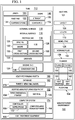
Figure 1 is an illustration of a block diagram of a manufacturing environment in accordance with an illustrative example; -
Figure 2 is an illustration of an isometric view of a heat pipe with a non-uniform cross-section in accordance with an illustrative example; -
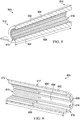
Figure 3 is an illustration of an isometric view of a first end of a heat pipe with a non-uniform cross-section in accordance with an illustrative example; -
Figure 4 is an illustration of an isometric view of a second end of a heat pipe with a non-uniform cross-section in accordance with an illustrative example; -
Figure 5 is an illustration of a cross-sectional view of a heat pipe with a non-uniform cross-section in accordance with an illustrative example; -
Figure 6 is an illustration of a cross-sectional view of a heat pipe with a non-uniform cross-section in accordance with an illustrative example; -
Figure 7 is an illustration of a flowchart of a method of manufacturing a heat pipe in accordance with an illustrative example; and -
Figure 8 is an illustration of a data processing system in the form of a block diagram in accordance with an illustrative example. - The different illustrative examples recognize and take into account one or more different considerations. For example, the illustrative examples recognize and take into account that extrusion creates uniform cross-sections within manufacturing tolerances.
- As another example, the illustrative examples recognize and take into account that the heat transport capacity of a heat pipe is affected by the length of the heat pipe and the design of the grooves of the heat pipe. The illustrative examples recognize and take into account that available pressure head may be described as

- The illustrative examples further recognize and take into account that welds or other types of joints may be weaker than a surrounding monolithic material. Material within welds have different material properties than a surrounding bulk material. The illustrative examples also recognize that monolithic structures can be manufactured using processes other than machining. For example, the illustrative examples recognize and take into account that extrusion, molding, and other manufacturing processes other than machining result in monolithic structures.
- Referring now to the figures and, in particular, with reference to
Figure 1 , an illustration of a block diagram of a manufacturing environment is depicted in accordance with an illustrative example.Manufacturing environment 100 includes equipment to formheat pipe 101. As depicted,manufacturing environment 100 includesadditive manufacturing equipment 102. -
Heat pipe 101 may be formed usingadditive manufacturing equipment 102. Conventional machining processes may form structures by shaping or removing material. Additive manufacturing processes form structures by adding material. Specifically, additive manufacturing processes may form structures by adding consecutive layers of material. Additive manufacturing may allow on-demand manufacture of desired parts. -
Additive manufacturing equipment 102 may take the form of three-dimensional printer 104 or any other desirable additive manufacturing equipment. In one illustrative example,additive manufacturing equipment 102 may formheat pipe 101 by sequentially forming a plurality of layers. The thickness of each of the plurality of layers may depend on the resolution ofadditive manufacturing equipment 102.Additive manufacturing equipment 102 may formheat pipe 101 frommaterial 106.Material 106 may take the form of at least one of a metal, a metallic alloy, or other desirable type of material. - As used herein, the phrase "at least one of," when used with a list of items, means different combinations of one or more of the listed items may be used, and only one of each item in the list may be needed. In other words, "at least one of" means any combination of items and number of items may be used from the list but not all of the items in the list are required. The item may be a particular object, a thing, or a category.
- For example, "at least one of item A, item B, or item C" may include, without limitation, item A, item A and item B, or item B. This example also may include item A, item B, and item C or item B and item C. Of course, any combinations of these items may be present. In other examples, "at least one of" may be, for example, without limitation, two of item A, one of item B, and ten of item C; four of item B and seven of item C; or other suitable combinations.
- By forming
heat pipe 101 usingadditive manufacturing equipment 102,layout 108 ofheat pipe 101 may be closely controlled. By formingheat pipe 101 usingadditive manufacturing equipment 102,layout 108 ofheat pipe 101 does not need to be uniform alonglength 110 ofheat pipe 101. -
Heat pipe 101 includestube 112 andprotrusions 114. In some illustrative examples,protrusions 114 may also be referred to as "fins", "lands" or "fin-like structures." Althoughprotrusions 114 may be referred to as "fins,"protrusions 114 do not have the primary purpose of conducting heat.Tube 112 hasinternal surface 116,external surface 118, andlength 120 running fromfirst end 122 tosecond end 124.Protrusions 114 extend alonginternal surface 116 in a direction oflength 120 oftube 112. - Although
tube 112 andprotrusions 114 are not machined from a single block of material, there are no joints or welds betweentube 112 andprotrusions 114.Tube 112 andprotrusions 114 are monolithic 125. At least one ofspacing 126,size 128, or shape 130 ofprotrusions 114 changes betweenfirst end 122 oftube 112 andsecond end 124 oftube 112. - By changing at least one of
spacing 126,size 128, or shape 130 ofprotrusions 114,protrusions 114 are tailored. By tailoringprotrusions 114, functioning ofheat pipe 101 is affected. For example, heat transport capacity ofheat pipe 101 is affected by tailoring at least one ofspacing 126,size 128, or shape 130 ofprotrusions 114. - In some illustrative examples, a height of at least one protrusion of
protrusions 114 changes alonglength 120 oftube 112. The height of a protrusion is the distance the protrusion extends away frominternal surface 116 oftube 112 and towards the center oftube 112.Protrusions 114 may change at least one ofspacing 126,size 128, or shape 130 continuously or in a discrete or step-wise manner. In some illustrative examples,protrusions 114 taper fromfirst end 122 tosecond end 124. In other illustrative examples, at least one protrusion ofprotrusions 114 terminates prior tosecond end 124. -
Protrusions 114 andinternal surface 116form grooves 131.Grooves 131transport working fluid 132 withinheat pipe 101.Grooves 131transport working fluid 132 by at least one of capillary action or gravity. In zero-g environments with no spinning forces, capillary forces do all the work to move workingfluid 132. In these environments,grooves 131 may be referred to as "capillary grooves." In "reflux" operation, there is a gravity assist. - Working
fluid 132 vaporizes atfirst end 122 and travels tosecond end 124. Workingfluid 132 condenses atsecond end 124 and travels back tofirst end 122 usinggrooves 131. The location, shape, and size ofgrooves 131 is controlled by controllingspacing 126,size 128, and shape 130 ofprotrusions 114. - In some illustrative examples, a design of
protrusions 114 improves a capillary pumping function ofgrooves 131 acting upon workingfluid 132 withinheat pipe 101. In some illustrative examples,first end 122 isevaporator end 134,second end 124 iscondenser end 136, and spacing 126 ofprotrusions 114 atevaporator end 134 is less than spacing 126 ofprotrusions 114 atcondenser end 136. - In some illustrative examples,
first end 122 isevaporator end 134 andsecond end 124 iscondenser end 136. In these illustrative examples, a design ofprotrusions 114 significantly restricts a heat load transferred to the evaporator when heat is applied tocondenser end 136. - In some illustrative examples,
heat pipe 101 includesflanges 138 extending fromexternal surface 118. In these illustrative examples,tube 112,protrusions 114, andflanges 138 are monolithic. By being monolithic, identifiable joints are not present. Thus,flanges 138 are not welded, or otherwise joined, totube 112. - In some illustrative examples,
flanges 138 are out of plane relative to each other.Flanges 138 are shaped and positioned to interface withheat source 140 andheat sink 142, that are not co-planar with each other. As depicted,flanges 138 includesflange 144 andflange 146.Flange 144 joinsheat pipe 101 to heatsource 140.Flange 146 joinsheat pipe 101 toheat sink 142. - In some illustrative examples,
flanges 146 are shaped and positioned to reducelength 110 ofheat pipe 101. Reducinglength 110 ofheat pipe 101 increases heat transport capacity ofheat pipe 101. In some illustrative examples,heat pipe 101 provides a shortest three-dimensional path fromheat source 140 toheat sink 142. -
Tube 112 hasshape 148. In some of these examples,tube 112 is substantially straight 150. Whentube 112 is substantially straight 150,length 110 ofheat pipe 101 may be minimized. In other illustrative examples,tube 112 is contoured 152.Tube 112 may be contoured 152 to take into account geometries of components ofplatform 154 havingheat source 140 andheat sink 142. -
Platform 154 may take any desirable form. Although the illustrative examples for an illustrative example are described with respect to a satellite, an illustrative example may be applied to other types of platforms.Platform 154 may be, for example, a mobile platform, a stationary platform, a land-based structure, an aquatic-based structure, or a space-based structure. More specifically,platform 154 may be a surface ship, a tank, a personnel carrier, a train, a spacecraft, a space station, a satellite, a submarine, an automobile, a manufacturing facility, a building, or other suitable types of platforms. Further,platform 154 may be a small-scale or handheld device such as a cell phone, tablet, computer, or other suitable type of platform. - In some illustrative examples,
heat pipe 101 comprisestube 112 andprotrusions 114.Tube 112 hasinternal surface 116,external surface 118, andlength 120 running fromfirst end 122 tosecond end 124.Protrusions 114 are oninternal surface 116.First cross-section 156 ofprotrusions 114 at a first location oflength 120 oftube 112 is different fromsecond cross-section 158 ofprotrusions 114 at a second location oflength 120 oftube 112, andtube 112 andprotrusions 114 are monolithic 125. - In some illustrative examples, a height of at least one protrusion of
protrusions 114 changes alonglength 120 oftube 112. In some illustrative examples, at least one protrusion ofprotrusions 114 terminates prior tosecond end 124. In some illustrative examples,protrusions 114form grooves 131, in whichgrooves 131 are a plurality of continuously variable grooves. -
Additive manufacturing equipment 102 may be a part of heatpipe forming system 160. Heatpipe forming system 160 may also includedatabase 162, computer-aideddesign software 164,controller 166, andheat treatment equipment 168. -
Heat treatment equipment 168 includes any desirable equipment to modify the material characteristics ofmaterial 106 ofheat pipe 101 aftermaterial 106 is laid down byadditive manufacturing equipment 102. For example,heat treatment equipment 168 may include a number of furnaces, autoclaves, or other equipment to perform hot isotropic pressing, tempering, or any other desirable heat treatment processes. - As depicted,
additive manufacturing equipment 102, such as three-dimensional printer 104, may be used to formheat pipe 101 based on three-dimensional model 170 stored indatabase 162. In this illustrative example,database 162 may be a storage device configured to store models, such as three-dimensional model 170. - In some illustrative examples, three-
dimensional model 170 may be used to formheat pipe 101. In some illustrative examples, three-dimensional model 170 may be a data file used to generateinstructions 172 to formheat pipe 101. In some illustrative examples, three-dimensional model 170 may be a data file formed usingdata regarding platform 154. For example, three-dimensional model 170 may take into account a desirable amount of heat transfer betweenheat source 140 andheat sink 142, a location ofheat source 140 withinplatform 154, a location ofheat sink 142 withinplatform 154, secondary structures ofplatform 154, or any other characteristics ofplatform 154. - As illustrated,
controller 166 may be a device configured to generateinstructions 172 foradditive manufacturing equipment 102 based on three-dimensional model 170 such thatadditive manufacturing equipment 102 forms heatpipe 101 in a desired manner. In this illustrative example,controller 166 may be implemented in software, hardware, firmware, or a combination thereof. When software is used, the operations performed bycontroller 166 may be implemented using, for example, without limitation, program code configured to run on a processor unit. When firmware is used, the operations performed bycontroller 166 may be implemented using, for example, without limitation, program code and data, and is stored in persistent memory to run on a processor unit. - When hardware is employed, the hardware may include one or more circuits that operate to perform the operations performed by
controller 166. Depending on the implementation, the hardware may take the form of a circuit system, an integrated circuit, an application-specific integrated circuit (ASIC), a programmable logic device, or some other suitable type of hardware device configured to perform any number of operations. - A programmable logic device may be configured to perform certain operations. The device may be permanently configured to perform these operations or may be reconfigurable. A programmable logic device may take the form of, for example, without limitation, a programmable logic array, a programmable array logic, a field programmable logic array, a field programmable gate array, or some other type of programmable hardware device.
- In some illustrative examples, the operations, processes or both, performed by
controller 166 may be performed using organic components integrated with inorganic components. In some cases, the operations, processes, or both may be performed by entirely of organic components, excluding a human being. As one illustrative example, circuits in organic semiconductors may be used to perform these operations, processes, or both. In this illustrative example,controller 166 may be implemented incomputer system 174. In other illustrative examples,controller 166 may be remote tocomputer system 174. - As depicted,
instructions 172 may be commands executable byadditive manufacturing equipment 102.Controller 166 may generateinstructions 172 in a format usable foradditive manufacturing equipment 102.Instructions 172 may then be sent toadditive manufacturing equipment 102 so thatadditive manufacturing equipment 102 may formheat pipe 101 frommaterial 106.Instructions 172 may be sent toadditive manufacturing equipment 102 via wireless communications links, wired communications links, another suitable type of communications medium, or a combination thereof. - The illustration of
manufacturing environment 100, and more specifically, ofheat pipe 101 and heatpipe forming system 160 and the components within heatpipe forming system 160 inFigure 1 , is not meant to imply physical or architectural limitations to the manner in which an illustrative example may be implemented. Other components in addition to or in place of the ones illustrated may be used. Some components may be optional. Also, the blocks are presented to illustrate some functional components. One or more of these blocks may be combined, divided, or combined and divided into different blocks when implemented in an illustrative example. - For example,
material 106 need not be a single material. In some illustrative examples,material 106 may be more than one material. - Turning now to
Figure 2 , an illustration of an isometric view of a heat pipe with a non-uniform cross-section is depicted in accordance with an illustrative example.Heat pipe 200 is a physical implementation ofheat pipe 101 ofFigure 1 .Heat pipe 200 includestube 202 andflanges 204 extending fromexternal surface 206 oftube 202.Tube 202 andflanges 204 are monolithic. - As depicted,
tube 202 is substantially straight and haslength 208. As depicted,flange 210 andflange 212 offlanges 204 are out of plane relative to each other, wherein the flanges are shaped and positioned to interface with a heat source and a heat sink that are not co-planar with each other. - As depicted,
flanges 204 are shaped and positioned to reducelength 208 ofheat pipe 200.Heat pipe 200 may have at least a length long enough to transfer heat from a heat source and a heat sink.Length 208 is sufficient to connectheat pipe 200 to the heat source and the heat sink. For example,first end 214 may be connected to an evaporator of a platform andsecond end 216 may be connected to a condenser of a platform. - Turning now to
Figure 3 , an illustration of an isometric view of a first end of a heat pipe with a non-uniform cross-section is depicted in accordance with an illustrative example. View 300 is a view offirst end 214 oftube 202 ofFigure 2 . When installed,first end 214 may be attached to an evaporator of a platform.First end 214 may be called an "evaporator end". - As depicted,
first end 214 hasprotrusions 302 visible.Protrusions 302 havespacing 304 andheight 306 atfirst end 214.Protrusions 302 run into the page withlength 208 ofheat pipe 200 shown inFigure 2 . Some ofprotrusions 302 may not extend the whole oflength 208 ofheat pipe 200. In some illustrative examples, at least one protrusion ofprotrusions 302 changes at least one of shape or size. - Turning now to
Figure 4 , an illustration of an isometric view of a second end of a heat pipe with a non-uniform cross-section is depicted in accordance with an illustrative example. View 400 is a view ofsecond end 216 oftube 202 ofFigure 2 . When installed,second end 216 may be attached to a condenser of a platform.Second end 216 may be called condenser end. - As depicted,
second end 216 hasprotrusions 302 visible.Protrusions 302 havespacing 402 andheight 404 atsecond end 216.Protrusions 302 run into the page withlength 208 ofheat pipe 200. Some ofprotrusions 302 may not extend the whole oflength 208 ofheat pipe 200. In some illustrative examples, at least one protrusion ofprotrusions 302 changes at least one of shape or size. - As depicted, spacing 402 is less than spacing 304 of
Figure 3 . Spacing 402 is less than spacing 304 because additional protrusions are present atsecond end 216 that are not present atfirst end 214. In this illustrative example,height 404 of protrusions atsecond end 216 is substantially the same asheight 306 of protrusions atfirst end 214. - As can be seen in
Figures 3 and 4 , cross-section atfirst end 214 is not the same as the cross-section atsecond end 216. Thus, the cross-section ofheat pipe 200 is non-uniform and cannot be directly manufactured using extrusion. - Turning now to
Figure 5 , an illustration of a cross-sectional view of a heat pipe with a non-uniform cross-section is depicted in accordance with an illustrative example.Heat pipe 500 is a physical implementation ofheat pipe 101 ofFigure 1 .Heat pipe 500 may be a physical implementation of the inside ofheat pipe 200 ofFigure 2 . - As depicted, and for simplicity of depiction only,
heat pipe 500 does not have multiple flanges inFigure 5 . However,heat pipe 500 may desirably have any number, position, or shape of flange to connect to a heat source and a heat sink. - As depicted,
heat pipe 500 hastube 502 havinginternal surface 504,external surface 506, andlength 508 running fromfirst end 510 tosecond end 512.Protrusions 514 are monolithic withtube 502.Protrusions 514 extend alonginternal surface 504 in a direction oflength 508 oftube 502. As depicted, each ofprotrusions 514 extends fromfirst end 510 tosecond end 512. - As depicted, each of
protrusions 514 decreases in height fromsecond end 512 tofirst end 510. Decreasing the height ofprotrusions 514 creates a non-uniform cross-section forheat pipe 500. The shape ofprotrusions 514 affects thermal resistance ofheat pipe 500. -
Grooves 516 are formed byprotrusions 514 andinternal surface 504. By changing the height ofprotrusions 514, the shape ofgrooves 516 changes fromfirst end 510 tosecond end 512. Tailoringgrooves 516 may increase transport capacity ofheat pipe 500. By tailoringgrooves 516 to a desired shape alonglength 508, transport capacity may be increased by twice or more. By tailoringgrooves 516,smaller heat pipe 500 sizes may result. Decreasing size ofheat pipe 500 includes reducing at least one oflength 508 or the diameter ofheat pipe 500. By decreasing the size ofheat pipe 500, the weight ofheat pipe 500 is also reduced. - Turning now to
Figure 6 , an illustration of a cross-sectional view of a heat pipe with a non-uniform cross-section is depicted in accordance with an illustrative example.Heat pipe 600 is a physical implementation ofheat pipe 101 ofFigure 1 .Heat pipe 600 may be a physical implementation of the inside ofheat pipe 200 ofFigure 2 . - As depicted, and for simplicity of depiction only,
heat pipe 600 does not have multiple flanges inFigure 6 . However,heat pipe 600 may desirably have any number, position, or shape of flange to connect to a heat source and a heat sink. - As depicted,
heat pipe 600 hastube 602 havinginternal surface 604,external surface 606, andlength 608 running fromfirst end 610 tosecond end 612.Protrusions 614 are monolithic withtube 602.Protrusions 614 extend alonginternal surface 604 in a direction oflength 608 oftube 602. As depicted, some ofprotrusions 614 do not fully extend fromsecond end 612 tofirst end 610. Thus, a quantity ofprotrusions 614 is reduced fromsecond end 612 tofirst end 610. - As depicted, first set 616 of
protrusions 614 extend fromsecond end 612 towardsfirst end 610 and terminates atlocation 617. Terminating first set 616 ofprotrusions 614 prior tofirst end 610 creates a non-uniform cross-section forheat pipe 600. -
Grooves 618 are formed byprotrusions 614 andinternal surface 604. By reducing the quantity ofprotrusions 614 fromfirst end 610 tosecond end 612, the shape ofgrooves 618 changes fromfirst end 610 tosecond end 612. Tailoringgrooves 618 may increase transport capacity ofheat pipe 600. By tailoringgrooves 618 to a desired shape alonglength 608, transport capacity may be increased by twice or more. By tailoringgrooves 618, smaller heat pipe sizes may result. - Turning now to
Figure 7 , an illustration of a flowchart of a method of manufacturing a heat pipe is depicted in accordance with an illustrative example.Method 700 may be used to formheat pipe 101 ofFigure 1 .Method 700 may be used to form any ofheat pipe 200,heat pipe 500, orheat pipe 600 inFigures 2 ,5 and 6 , respectively. -
Method 700 lays down material using additive manufacturing to form a heat pipe comprising a tube and protrusions, wherein the tube has an internal surface, an external surface, and a length running from a first end to a second end, wherein the protrusions are on the internal surface, and wherein a first cross-section of the protrusions at a first location of the length of the tube is different from a second cross-section of the protrusions at a second location of the length of the tube (operation 702).Method 700 hot isotropic presses the heat pipe to reduce porosity and increase strength (operation 704).Method 700 heat treats the heat pipe to increase strength (operation 706). Afterwards, the process terminates. - The flowcharts and block diagrams in the different depicted examples illustrate the architecture, functionality, and operation of some possible implementations of apparatus and methods in an illustrative example. In this regard, each block in the flowcharts or block diagrams may represent a module, a segment, a function, and/or a portion of an operation or step.
- In some alternative implementations of an illustrative example, the function or functions noted in the blocks may occur out of the order noted in the figures. For example, in some cases, two blocks shown in succession may be executed substantially concurrently, or the blocks may sometimes be performed in the reverse order, depending upon the functionality involved. Also, other blocks may be added in addition to the illustrated blocks in a flowchart or block diagram.
- For example, in
method 700, laying down the material using additive manufacturing may further comprise forming flanges extending from the external surface, wherein the flanges are at arbitrary angles with respect to each other. As another example, inmethod 700, the tube is contoured to produce a shortest path from a heat source to a heat sink of a platform, taking into account surrounding structures of the platform. - Turning now to
Figure 8 , an illustration of a data processing system in the form of a block diagram is depicted in accordance with an illustrative example.Data processing system 800 may be used to implementcomputer system 174 ofFigure 1 . As depicted,data processing system 800 includescommunications framework 802, which provides communications betweenprocessor unit 804,storage devices 806,communications unit 808, input/output unit 810, anddisplay 812. In some cases,communications framework 802 may be implemented as a bus system. -
Processor unit 804 is configured to execute instructions for software to perform a number of operations.Processor unit 804 may comprise a number of processors, a multi-processor core, and/or some other suitable type of processor, depending on the implementation. In some cases,processor unit 804 may take the form of a hardware unit, such as a circuit system, an application specific integrated circuit (ASIC), a programmable logic device, or some other suitable type of hardware unit. - Instructions for the operating system, applications, and/or programs run by
processor unit 804 may be located instorage devices 806.Storage devices 806 may be in communication withprocessor unit 804 throughcommunications framework 802. As used herein, a storage device, also referred to as a computer-readable storage device, is any piece of hardware capable of storing information on a temporary and/or permanent basis. This information may include, but is not limited to, data, a program code, and/or other information. -
Memory 814 andpersistent storage 816 are examples ofstorage devices 806.Memory 814 may take the form of, for example, a random access memory or some type of volatile or non-volatile storage device.Persistent storage 816 may comprise any number of components or devices. For example,persistent storage 816 may comprise a hard drive, a flash memory drive, a rewritable optical disk, a rewritable magnetic tape, or some combination of the above. The media used bypersistent storage 816 may or may not be removable. -
Communications unit 808 allowsdata processing system 800 to communicate with other data processing systems and/or devices.Communications unit 808 may provide communications using physical and/or wireless communications links. - Input/
output unit 810 allows input to be received from, and output to be sent to other devices connected todata processing system 800. For example, input/output unit 810 may allow user input to be received through a keyboard, a mouse, and/or some other type of input device. As another example, input/output unit 810 may allow output to be sent to a printer connected todata processing system 800. -
Display 812 is configured to display information to a user.Display 812 may comprise, for example, without limitation, a monitor, a touch screen, a laser display, a holographic display, a virtual display device, and/or some other type of display device. - In this illustrative example, the processes of the different illustrative examples may be performed by
processor unit 804 using computer-implemented instructions. These instructions may be referred to as a program code, a computer-usable program code, or a computer-readable program code, and may be read and executed by one or more processors inprocessor unit 804. - In these examples,
program code 818 is located in a functional form on computer-readable media 820, which is selectively removable, and may be loaded onto or transferred todata processing system 800 for execution byprocessor unit 804.Program code 818 and computer-readable media 820 together formcomputer program product 822. In this illustrative example, computer-readable media 820 may be computer-readable storage media 824 or computer-readable signal media 826. - Computer-
readable storage media 824 is a physical or tangible storage device used to storeprogram code 818, rather than a medium that propagates or transmitsprogram code 818. Computer-readable storage media 824 may be, for example, without limitation, an optical or magnetic disk, or a persistent storage device that is connected todata processing system 800. - Alternatively,
program code 818 may be transferred todata processing system 800 using computer-readable signal media 826. Computer-readable signal media 826 may be, for example, a propagated data signal containingprogram code 818. This data signal may be an electromagnetic signal, an optical signal, and/or some other type of signal that can be transmitted over physical and/or wireless communications links. - The illustration of
data processing system 800 inFigure 8 is not meant to provide architectural limitations to the manner in which the illustrative examples may be implemented. The different illustrative examples may be implemented in a data processing system that includes components in addition to or in place of those illustrated fordata processing system 800. Further, components shown inFigure 8 may be varied from the illustrative examples shown. - The illustrative examples provide a method and apparatus for forming a heat pipe having a non-uniform cross-section. More specifically, the illustrative examples provide a method and apparatus for forming a heat pipe having tailored grooves for heat transportation of a platform.
- Additive machining allows reduced pressure drops at the condenser end by using bigger grooves where pumping is not as challenged. Groove shape may be optimized to provide the desired pumping. In one example, groove shape changes in multiple steps along the passage. In another example, groove shape changes in a continuous manner rather than a step-wise manner.
- Today's heat pipes use internally-grooved capillary wall structure manufactured by extrusion. The geometric cross section of these pipes, including flanges, is uniform throughout the length. These illustrative examples use additive machining to create the wall structure. This approach allows for tailoring of the shape and number of grooves along the length, yielding improved heat transport. Heat pipe contour can then be shaped to yield the shortest three-dimensional path from source to sink. External flanges required to interface with the heat source and heat sink are added with the optimum shape and location to allow for the shortest path with the easiest installation.
- Transporting heat efficiently from the heat source to heat sink within spacecraft and other platforms in geometries where the heat source and the heat sink transfer surfaces are at random compound angles relative to each other, i.e. not aligned, in plane or orthogonal to each other.
- With today's extruded heat pipes, operators may be faced with imposing seven or eight bends along the length of a heat pipe to get the uniform extruded flanges to line up with the heat input and output (source and sink) surfaces. This makes the heat pipes expensive to manufacture, longer, less capable of moving heat (due to the length) and heavier. These heat pipes are also very difficult to design, leading to expensive development efforts. These three-dimensional bent heat pipes also occupy significant volume and are thus restrictive to other spacecraft hardware and difficult to integrate. With uniform groove shape along the length of today's extruded heat pipes, a designer balances the desire to make the grooves small to provide high capillary pumping with the goal to promote easy flow of the liquid from the condenser to the evaporator to reduce pressure drops. This balance inevitably leads to a compromise position, with the grooves small enough to pump as much fluid as possible, through grooves big enough to let the fluid pass through. With additive manufacturing, the groove dimensions can be tailored along the heat pipe length to provide two times or more increase in the heat transport capability of the heat pipe.
- With additive machining, the heat pipe can be designed to take the shortest or most convenient path from the heat source to heat sink with flanges optimally-shaped to conform to the heat transfer surfaces of the heat source and heat sink. Similarly, the internal groove structure of the heat pipe can be optimized along the length of the heat pipe to provide the maximum pumping head at the evaporator (smallest grooves) and the minimum viscous pressure drop in the transport and condenser ends of the heat pipe. Additive manufacturing would also allow heat pipes of non-cylindrical shape to be manufactured with flatter cross-sections to better promote heat transfer from flat heat input and output surfaces, thus reducing the temperature differences in the metal flanges of today's heat pipes. Flatter heat pipes are less capable of reacting the internal pressure and resultant forces within the heat pipe and are more likely to deform or bow out under this pressure. Flatter configurations may include strengthening features either internally or externally to support the flatter external walls. For example, stiffeners or braces may be present to support flatter external walls.
- Tailoring grooves for a heat pipe allows the heat pipe to take shortest or most convenient path from the heat source to heat sink. The heat pipes of the illustrative examples may have an increased heat load capacity. Further, the heat pipes of the illustrative examples may also have reduced mass. Tailoring grooves for a heat pipe may result in a less complex shape for the heat pipe. A less complex heat pipe is easier to integrate in a platform.
- The illustrative examples do not need to bend the heat pipe, resulting in one less step in the process. The illustrative examples may have the flanges independently positioned on circumference where needed. Flanges with optimum shape include features to reduce thermal resistance. For example, a gusset may be positioned to improve conduction heat flow between the heat pipe and the flange.
- Tailored heat pipes may result in fewer and/or smaller heat pipes. Tailored heat pipes may result in reduced mass and cost.
- Groove structures can be tailored along the length of the heat pipe. Partial thermal diode effect can be built in for resiliency. An end cap of the heat pipe can be included to reduce the number of parts and operations.
- Roughness may result from additive manufacturing. Roughness in a heat pipe may reduce Q×Leff, which may lead to boiling. However, the roughness is good for reflux. Roughness in the heat pipe due to additive manufacturing may be reduced by heat treatments, such as hot isotopic processing.
- The illustrative examples provide a method and apparatus for a heat pipe in which the internal fins change either density, or height (or both) as they extend down the inside of the tube so the cross-sectional area of the wicking material changed through the length of the tube. These illustrative examples improve the pumping function.
- One illustrative example of the heat pipe will have variable capillary wall structures. In some illustrative examples, the heat pipe has continuously variable capillary wall structures where the fins taper across the heat pipe cross section.
- The apparatus for grooved heat pipe having a variable cross section produced is produced using additive machining. This structural form cannot be produced out of axially grooved extruded heat pipes.
- The design allows tailoring of the shape and number of grooves along the length yielding improved heat transport. This variable cross section allows customization for the heat transfer needs.
- The heat pipe contour can be shaped to yield the shortest three-dimensional path from heat source to heat sink. External flanges used to interface with the heat source and heat sink are added with the optimum shape and location to allow for the shortest path with the easiest installation. This allows much shorter heat pipes to be designed. Further, applying flanges at offset angles allows the heat pipe to move heat from two arbitrarily oriented locations without manufacturing impacts due to bending heat pipes.
- The design permits a greater density of grooves near the evaporator versus the condenser. This greater density of grooves near the evaporator enables heat pipes to transport more heat.
- Moving heat efficiently from heat source to heat sink is difficult within spacecraft and other platforms in geometries where the source and sink heat transfer surfaces are at random angles relative to each other.
- One of the features of the illustrative examples is the ability of additive machining to deliver structural forms that cannot be formed for axially grooved extruded heat pipes. Some examples of the heat pipe have the internal fins that change either density, or height (or both) as they extend down the inside of the tube so the cross-sectional area changes along heat pipe. Three-dimensional printing provides features, such as the ability to apply flanges in the position and shape desired. This ability to apply flanges allows much shorter heat pipes.
- The complex three-dimensional shape of a conventional heat pipe described is forced by the need to bend the extrusion (not twist) to get the flanges to line up with the heat sink and heat source locations. The concept of additive manufacturing allows this to be done with a much shorter, more capable, lighter additive manufactured heat pipe. Other advantages can be gained by changing the groove structure as the grooves progress from the evaporator to the condenser.
- The description of the different illustrative examples has been presented for purposes of illustration and description, and is not intended to be exhaustive or limited to the examples in the form disclosed. Many modifications and variations will be apparent to those of ordinary skill in the art. Further, different illustrative examples may provide different features as compared to other illustrative examples. The example or examples selected are chosen and described in order to best explain the principles of the examples, the practical application, and to enable others of ordinary skill in the art to understand the disclosure for various examples with various modifications as are suited to the particular use contemplated.
- Additional embodiments and features of the present disclosure are presented below without limitation. Features of each of these embodiments may be combined with one or more other embodiments from elsewhere in this disclosure, in any suitable manner.
- According to one embodiment, there is provided a heat pipe comprising: a tube having an internal surface, an external surface, and a length running from a first end to a second end; and protrusions extending along the internal surface in a direction of the length of the tube, wherein at least one of a spacing, a size, or a shape of the protrusions changes between the first end of the tube and the second end of the tube, wherein the tube and the protrusions are monolithic.
- Optionally, a height of at least one protrusion of the protrusions changes along the length of the tube.
- Optionally, at least one protrusion of the protrusions terminates prior to the second end.
- Optionally, the first end is an evaporator end, wherein the second end is a condenser end, and wherein a spacing of protrusions at the evaporator end is less than a spacing of protrusions at the condenser end.
- Optionally, the protrusions taper from the first end to the second end.
- Optionally, the heat pipe further comprises:
- flanges extending from the external surface, wherein the tube, the protrusions, and the flanges are monolithic.
- Optionally, the flanges are out of plane relative to each other.
- Optionally, the flanges are shaped and positioned to interface with a heat source and a heat sink that are not co-planar with each other.
- Optionally, the flanges are shaped and positioned to reduce the length of the heat pipe.
- Optionally, a design of the protrusions improves a capillary pumping function of a working fluid within the heat pipe.
- Optionally, the tube is contoured to produce a shortest path from a heat source to a heat sink of a platform taking into account surrounding structures of the platform.
- Optionally, the first end is an evaporator end, wherein the second end is a condenser end, and wherein a design of the protrusions significantly restricts a heat load transferred to an evaporator when heat is applied to the condenser end.
- According to a further embodiment, there is provided a heat pipe comprising: a tube having an internal surface, an external surface, and a length running from a first end to a second end; and protrusions on the internal surface, wherein a first cross-section of the protrusions at a first location of the length of the tube is different from a second cross-section of the protrusions at a second location of the length of the tube, and wherein the tube and the protrusions are monolithic.
- Optionally, a height of at least one protrusion of the protrusions changes along the length of the tube.
- Optionally, at least one protrusion of the protrusions terminates prior to the second end.
- Optionally, the heat pipe provides a shortest three-dimensional path from a heat source to a heat sink.
- Optionally, the protrusions form a plurality of continuously variable grooves.
- According to a further embodiment, there is provided a method comprising: laying down material using additive manufacturing to form a heat pipe comprising a tube and protrusions, wherein the tube has an internal surface, an external surface, and a length running from a first end to a second end, wherein the protrusions are on the internal surface, and wherein a first cross-section of the protrusions at a first location of the length of the tube is different from a second cross-section of the protrusions at a second location of the length of the tube; hot isotropic pressing the heat pipe to reduce porosity; and heat treating the heat pipe to increase strength.
- Optionally, laying down the material using additive manufacturing further comprises forming flanges extending from the external surface, wherein the flanges are at arbitrary angles with respect to each other.
- Optionally, the tube is contoured to produce a shortest path from a heat source to a heat sink of a platform taking into account surrounding structures of the platform.
Claims (15)
- A heat pipe (101) comprising:a tube (112) having an internal surface (116), an external surface (118), and a length (120) running from a first end (122) to a second end (124); andprotrusions (114) extending along the internal surface (116) in a direction of the length (120) of the tube (112), wherein at least one of a spacing (126), a size (128), or a shape (130) of the protrusions (114) changes between the first end (122) of the tube (112) and the second end (124) of the tube (112), wherein the tube (112) and the protrusions (114) are monolithic (125).
- The heat pipe (101) of claim 1, wherein a height of at least one protrusion of the protrusions (114) changes along the length (120) of the tube (112).
- The heat pipe (101) of claim 1 or 2, wherein at least one protrusion of the protrusions (114) terminates prior to the second end (124).
- The heat pipe (101) of any one of claims 1-3, wherein the first end (122) is an evaporator end (134), wherein the second end (124) is a condenser end (136), and wherein a spacing (126) of protrusions (114) at the evaporator end (134) is less than a spacing (126) of protrusions (114) at the condenser end (136).
- The heat pipe (101) of any one of claims 1-4, wherein the protrusions (114) taper from the first end (122) to the second end (124).
- The heat pipe (101) of any one of claims 1-5 further comprising:flanges (138) extending from the external surface (118), wherein the tube (112), the protrusions (114), and the flanges (138) are monolithic (125).
- The heat pipe (101) of claim 6, wherein the flanges (138) are out of plane relative to each other.
- The heat pipe (101) of claim 6 or claim 7, wherein the flanges (138) are shaped and positioned to interface with a heat source (140) and a heat sink (142) that are not co-planar with each other.
- The heat pipe (101) of claim 8, wherein the flanges (138) are shaped and positioned to reduce the length (120) of the heat pipe (101).
- The heat pipe (101) of any one of claims 1-9, wherein the tube (112) is contoured (152) to produce a shortest path from a heat source (140) to a heat sink (142) of a platform (154) taking into account surrounding structures of the platform (154).
- The heat pipe (101) of any one of claims 1-10, wherein the first end (122) is an evaporator end (134), wherein the second end (124) is a condenser end (136), and wherein a design of the protrusions (114) significantly restricts a heat load transferred to an evaporator when heat is applied to the condenser end (136).
- The heat pipe (101) of any one of claims 1-11, wherein a first cross-section (156) of the protrusions (114) at a first location of the length (120) of the tube (112) is different from a second cross-section (158) of the protrusions (114) at a second location of the length (120) of the tube (112).
- A method comprising:laying down material (106) using additive manufacturing to form a heat pipe (101) comprising a tube (112) and protrusions (114), wherein the tube (112) has an internal surface (116), an external surface (118), and a length (120) running from a first end (122) to a second end (124), wherein the protrusions (114) are on the internal surface (116), and wherein a first cross-section (156) of the protrusions (114) at a first location of the length (120) of the tube (112) is different from a second cross-section (158) of the protrusions (114) at a second location of the length (120) of the tube (112);hot isotropic pressing the heat pipe (101) to reduce porosity; andheat treating the heat pipe (101) to increase strength.
- The method of claim 13, wherein laying down the material (106) using additive manufacturing further comprises forming flanges (138) extending from the external surface (118), wherein the flanges (138) are at arbitrary angles with respect to each other.
- The method of claim 13 or claim 14, wherein the tube (112) is contoured (152) to produce a shortest path from a heat source (140) to a heat sink (142) of a platform (154) taking into account surrounding structures of the platform (154).
Applications Claiming Priority (1)
| Application Number | Priority Date | Filing Date | Title |
|---|---|---|---|
| US15/398,790 US10480866B2 (en) | 2017-01-05 | 2017-01-05 | Heat pipe with non-uniform cross-section |
Publications (2)
| Publication Number | Publication Date |
|---|---|
| EP3346220A1 true EP3346220A1 (en) | 2018-07-11 |
| EP3346220B1 EP3346220B1 (en) | 2021-02-03 |
Family
ID=60661820
Family Applications (1)
| Application Number | Title | Priority Date | Filing Date |
|---|---|---|---|
| EP17206431.3A Active EP3346220B1 (en) | 2017-01-05 | 2017-12-11 | Heat pipe with non-uniform cross-section |
Country Status (4)
| Country | Link |
|---|---|
| US (1) | US10480866B2 (en) |
| EP (1) | EP3346220B1 (en) |
| JP (1) | JP7168318B2 (en) |
| CN (1) | CN108278915B (en) |
Cited By (7)
| Publication number | Priority date | Publication date | Assignee | Title |
|---|---|---|---|---|
| EP3736519A1 (en) * | 2019-05-08 | 2020-11-11 | Siemens Aktiengesellschaft | Evaporator-condenser assembly |
| EP3854590A1 (en) * | 2020-01-24 | 2021-07-28 | Hamilton Sundstrand Corporation | Radial configuration for heat exchanger core |
| CN113365769A (en) * | 2018-12-12 | 2021-09-07 | 麦格纳国际公司 | Additive manufacturing heat dissipation device |
| US11441850B2 (en) | 2020-01-24 | 2022-09-13 | Hamilton Sundstrand Corporation | Integral mounting arm for heat exchanger |
| US11453160B2 (en) | 2020-01-24 | 2022-09-27 | Hamilton Sundstrand Corporation | Method of building a heat exchanger |
| US11460252B2 (en) | 2020-01-24 | 2022-10-04 | Hamilton Sundstrand Corporation | Header arrangement for additively manufactured heat exchanger |
| US12246647B2 (en) | 2023-06-16 | 2025-03-11 | Magna Mirrors Of America, Inc. | Vehicular interior rearview mirror assembly with heatsink |
Families Citing this family (7)
| Publication number | Priority date | Publication date | Assignee | Title |
|---|---|---|---|---|
| EP2527776A1 (en) | 2011-05-24 | 2012-11-28 | Thermal Corp. | Capillary device for use in heat pipe and method of manufacturing such capillary device |
| CN109297329B (en) * | 2018-09-03 | 2020-07-14 | 北京空间机电研究所 | Channel heat pipe with circumferential channel and connecting method thereof |
| US11781814B2 (en) * | 2020-03-16 | 2023-10-10 | The Boeing Company | Tapered groove width heat pipe |
| JP7550682B2 (en) | 2021-03-05 | 2024-09-13 | 三菱重工業株式会社 | Heat pipe |
| JP7689857B2 (en) | 2021-04-01 | 2025-06-09 | 三菱重工業株式会社 | Cooling System |
| CN114413675B (en) * | 2021-12-15 | 2023-10-13 | 合肥通用机械研究院有限公司 | A pipe with Laval structure on its inner surface and its additive manufacturing method |
| US20250067373A1 (en) * | 2022-01-07 | 2025-02-27 | Electric Power Research Institute, Inc. | Methodology to Enable the Use of Oxide Dispersion Strengthened Alloys and Precipitation Strengthen Nickel-Based Alloys for Advanced Energy Systems |
Citations (3)
| Publication number | Priority date | Publication date | Assignee | Title |
|---|---|---|---|---|
| JPS5618584U (en) * | 1979-07-23 | 1981-02-18 | ||
| JPS63183392A (en) * | 1987-01-22 | 1988-07-28 | Mitsubishi Metal Corp | Heat transfer pipe |
| EP3252419A1 (en) * | 2016-06-02 | 2017-12-06 | ABB Technology Oy | Gravity-assisted heat pipe |
Family Cites Families (20)
| Publication number | Priority date | Publication date | Assignee | Title |
|---|---|---|---|---|
| US3537514A (en) * | 1969-03-12 | 1970-11-03 | Teledyne Inc | Heat pipe for low thermal conductivity working fluids |
| US4116266A (en) * | 1974-08-02 | 1978-09-26 | Agency Of Industrial Science & Technology | Apparatus for heat transfer |
| JPS595048B2 (en) * | 1976-05-20 | 1984-02-02 | 株式会社神戸製鋼所 | Manufacturing method of raw tube for unidirectional heat pipe |
| US4489777A (en) * | 1982-01-21 | 1984-12-25 | Del Bagno Anthony C | Heat pipe having multiple integral wick structures |
| JPH0346355A (en) * | 1989-07-14 | 1991-02-27 | Furukawa Electric Co Ltd:The | Heat-transportation device of heat-pipe system |
| US5010951A (en) * | 1989-08-03 | 1991-04-30 | Lockhead Missiles & Space Company, Inc. | Graded-groove heat pipe |
| US5598632A (en) * | 1994-10-06 | 1997-02-04 | The United States Of America As Represented By The Administrator Of The National Aeronautics And Space Administration | Method for producing micro heat panels |
| JP3355077B2 (en) * | 1995-10-02 | 2002-12-09 | 三菱電機株式会社 | Heat pipe and its manufacturing method |
| US5725050A (en) * | 1996-09-03 | 1998-03-10 | Thermal Corp. | Integrated circuit with taped heat pipe |
| JP3268734B2 (en) * | 1996-11-15 | 2002-03-25 | 古河電気工業株式会社 | Method of manufacturing electronic device heat radiation unit using heat pipe |
| TW591363B (en) | 2001-10-10 | 2004-06-11 | Aavid Thermalloy Llc | Heat collector with mounting plate |
| JP2003262480A (en) | 2002-03-06 | 2003-09-19 | Hitachi Cable Ltd | Flat heat pipe, method of manufacturing the same, and cooling system using the same |
| RU2382310C2 (en) * | 2004-11-03 | 2010-02-20 | Велосис, Инк. | Method of partial boiling in mini- and microchannels |
| JP2008014528A (en) | 2006-07-04 | 2008-01-24 | Furukawa Electric Co Ltd:The | Heat sink parts |
| JP5618584B2 (en) | 2010-03-18 | 2014-11-05 | 株式会社トクヤマ | Fuel for polymer electrolyte fuel cells |
| CN102809314A (en) * | 2012-08-31 | 2012-12-05 | 苏州浩佳节能科技有限公司 | Three-dimensional heat-pipe heat exchanger and production method thereof |
| US20150237762A1 (en) * | 2014-02-20 | 2015-08-20 | Raytheon Company | Integrated thermal management system |
| US9796137B2 (en) | 2015-06-08 | 2017-10-24 | The Boeing Company | Additive manufacturing methods |
| CN105689717B (en) * | 2016-02-25 | 2018-10-30 | 重庆大学 | A kind of method for manufacturing parts being embedded with capillary structure pipeline |
| CN106524805B (en) * | 2016-12-02 | 2018-12-04 | 廖忠民 | Heat pipe radiator with conformal vertical heat conducting surface |
-
2017
- 2017-01-05 US US15/398,790 patent/US10480866B2/en active Active
- 2017-12-11 EP EP17206431.3A patent/EP3346220B1/en active Active
- 2017-12-21 CN CN201711390287.3A patent/CN108278915B/en active Active
- 2017-12-22 JP JP2017246018A patent/JP7168318B2/en active Active
Patent Citations (3)
| Publication number | Priority date | Publication date | Assignee | Title |
|---|---|---|---|---|
| JPS5618584U (en) * | 1979-07-23 | 1981-02-18 | ||
| JPS63183392A (en) * | 1987-01-22 | 1988-07-28 | Mitsubishi Metal Corp | Heat transfer pipe |
| EP3252419A1 (en) * | 2016-06-02 | 2017-12-06 | ABB Technology Oy | Gravity-assisted heat pipe |
Cited By (10)
| Publication number | Priority date | Publication date | Assignee | Title |
|---|---|---|---|---|
| CN113365769A (en) * | 2018-12-12 | 2021-09-07 | 麦格纳国际公司 | Additive manufacturing heat dissipation device |
| EP3894123A4 (en) * | 2018-12-12 | 2022-01-19 | Magna International Inc. | ADDITIVELY MANUFACTURED HEATSINK |
| EP3736519A1 (en) * | 2019-05-08 | 2020-11-11 | Siemens Aktiengesellschaft | Evaporator-condenser assembly |
| EP3854590A1 (en) * | 2020-01-24 | 2021-07-28 | Hamilton Sundstrand Corporation | Radial configuration for heat exchanger core |
| US11441850B2 (en) | 2020-01-24 | 2022-09-13 | Hamilton Sundstrand Corporation | Integral mounting arm for heat exchanger |
| US11453160B2 (en) | 2020-01-24 | 2022-09-27 | Hamilton Sundstrand Corporation | Method of building a heat exchanger |
| US11460252B2 (en) | 2020-01-24 | 2022-10-04 | Hamilton Sundstrand Corporation | Header arrangement for additively manufactured heat exchanger |
| US11703283B2 (en) | 2020-01-24 | 2023-07-18 | Hamilton Sundstrand Corporation | Radial configuration for heat exchanger core |
| US11752691B2 (en) | 2020-01-24 | 2023-09-12 | Hamilton Sundstrand Corporation | Method of building a heat exchanger |
| US12246647B2 (en) | 2023-06-16 | 2025-03-11 | Magna Mirrors Of America, Inc. | Vehicular interior rearview mirror assembly with heatsink |
Also Published As
| Publication number | Publication date |
|---|---|
| JP7168318B2 (en) | 2022-11-09 |
| EP3346220B1 (en) | 2021-02-03 |
| CN108278915A (en) | 2018-07-13 |
| US10480866B2 (en) | 2019-11-19 |
| US20180187979A1 (en) | 2018-07-05 |
| JP2018162962A (en) | 2018-10-18 |
| CN108278915B (en) | 2021-11-23 |
Similar Documents
| Publication | Publication Date | Title |
|---|---|---|
| EP3346220A1 (en) | Heat pipe with non-uniform cross-section | |
| Khrustalev et al. | Heat transfer during evaporation on capillary-grooved structures of heat pipes | |
| Gravouil et al. | Multi‐time‐step explicit–implicit method for non‐linear structural dynamics | |
| Gay Neto et al. | A comparative wet collapse buckling study for the carcass layer of flexible pipes | |
| JP5788074B1 (en) | heat pipe | |
| Golovashchenko et al. | Two-step method of forming complex shapes from sheet metal | |
| CN109496261B (en) | 3D Spiral Heat Exchanger | |
| US20140060781A1 (en) | Heat pipe and method for manufactureing the same | |
| US20190354650A1 (en) | Analytical Tools and Method for Modeling Transport Processes in Fluids | |
| Mueller et al. | Novel design integration for advanced nuclear heat-pipe systems | |
| Jie Liu et al. | Porous media modeling of two-phase microchannel cooling of electronic chips with nonuniform power distribution | |
| TW202140980A (en) | Wick assembly for use with a heat pipe, heat pipe and method of constructing the wick assembly for use with the heat pipe | |
| Han et al. | Manufacturing of a corrugated double-layered tube for the high-performance compact heat exchanger | |
| Al Ketbi et al. | Simulation based investigation of Nusselt number and Poiseuille number in helical microchannels | |
| Haddout et al. | Convective heat transfer for a gaseous slip flow in micropipe and parallel-plate microchannel with uniform wall heat flux: effect of axial heat conduction | |
| Burchitz et al. | Adaptive through‐thickness integration for accurate springback prediction | |
| Kaushik et al. | Computational analysis of a pulsed power source-based electromagnetic manufacturing process | |
| Abbas et al. | Collapsing plane symmetric source with heat flux and conformal flatness | |
| Yang et al. | Preform design for tube hydroforming based on wrinkle formation | |
| Baniamerian et al. | Simulation of boiling heat transfer within water jacket of 4-cylinder gasoline engine | |
| Thipprakmas et al. | Comparison of offset and wiping Z-die designs for precision Z-bent part fabrication | |
| Hernandez et al. | Comparison of reliability based structural optimization methodologies in the design of aircraft structures | |
| Li et al. | Reliability analysis of the tube hydroforming process based on forming limit diagram | |
| Zheng et al. | Multi-objective optimization of Ω-shaped reentrant microchannels by numerical simulation and genetic algorithm | |
| Kim et al. | Investigation into hydromechanical reverse redrawing assisted by separate radial pressure—process development and theoretical verification |
Legal Events
| Date | Code | Title | Description |
|---|---|---|---|
| PUAI | Public reference made under article 153(3) epc to a published international application that has entered the european phase |
Free format text: ORIGINAL CODE: 0009012 |
|
| STAA | Information on the status of an ep patent application or granted ep patent |
Free format text: STATUS: REQUEST FOR EXAMINATION WAS MADE |
|
| 17P | Request for examination filed |
Effective date: 20171211 |
|
| AK | Designated contracting states |
Kind code of ref document: A1 Designated state(s): AL AT BE BG CH CY CZ DE DK EE ES FI FR GB GR HR HU IE IS IT LI LT LU LV MC MK MT NL NO PL PT RO RS SE SI SK SM TR |
|
| AX | Request for extension of the european patent |
Extension state: BA ME |
|
| GRAP | Despatch of communication of intention to grant a patent |
Free format text: ORIGINAL CODE: EPIDOSNIGR1 |
|
| STAA | Information on the status of an ep patent application or granted ep patent |
Free format text: STATUS: GRANT OF PATENT IS INTENDED |
|
| RIC1 | Information provided on ipc code assigned before grant |
Ipc: F28D 15/02 20060101ALI20200317BHEP Ipc: F28F 1/00 20060101ALI20200317BHEP Ipc: B23P 15/26 20060101ALI20200317BHEP Ipc: B33Y 80/00 20150101ALI20200317BHEP Ipc: F28F 1/40 20060101AFI20200317BHEP Ipc: F28D 15/04 20060101ALI20200317BHEP Ipc: F28F 13/08 20060101ALI20200317BHEP |
|
| INTG | Intention to grant announced |
Effective date: 20200401 |
|
| GRAJ | Information related to disapproval of communication of intention to grant by the applicant or resumption of examination proceedings by the epo deleted |
Free format text: ORIGINAL CODE: EPIDOSDIGR1 |
|
| STAA | Information on the status of an ep patent application or granted ep patent |
Free format text: STATUS: REQUEST FOR EXAMINATION WAS MADE |
|
| GRAP | Despatch of communication of intention to grant a patent |
Free format text: ORIGINAL CODE: EPIDOSNIGR1 |
|
| STAA | Information on the status of an ep patent application or granted ep patent |
Free format text: STATUS: GRANT OF PATENT IS INTENDED |
|
| INTC | Intention to grant announced (deleted) | ||
| INTG | Intention to grant announced |
Effective date: 20200708 |
|
| GRAS | Grant fee paid |
Free format text: ORIGINAL CODE: EPIDOSNIGR3 |
|
| GRAA | (expected) grant |
Free format text: ORIGINAL CODE: 0009210 |
|
| STAA | Information on the status of an ep patent application or granted ep patent |
Free format text: STATUS: THE PATENT HAS BEEN GRANTED |
|
| AK | Designated contracting states |
Kind code of ref document: B1 Designated state(s): AL AT BE BG CH CY CZ DE DK EE ES FI FR GB GR HR HU IE IS IT LI LT LU LV MC MK MT NL NO PL PT RO RS SE SI SK SM TR |
|
| REG | Reference to a national code |
Ref country code: GB Ref legal event code: FG4D |
|
| REG | Reference to a national code |
Ref country code: AT Ref legal event code: REF Ref document number: 1359795 Country of ref document: AT Kind code of ref document: T Effective date: 20210215 Ref country code: CH Ref legal event code: EP |
|
| REG | Reference to a national code |
Ref country code: DE Ref legal event code: R096 Ref document number: 602017032334 Country of ref document: DE |
|
| REG | Reference to a national code |
Ref country code: IE Ref legal event code: FG4D |
|
| REG | Reference to a national code |
Ref country code: NL Ref legal event code: MP Effective date: 20210203 |
|
| REG | Reference to a national code |
Ref country code: LT Ref legal event code: MG9D |
|
| REG | Reference to a national code |
Ref country code: AT Ref legal event code: MK05 Ref document number: 1359795 Country of ref document: AT Kind code of ref document: T Effective date: 20210203 |
|
| PG25 | Lapsed in a contracting state [announced via postgrant information from national office to epo] |
Ref country code: NO Free format text: LAPSE BECAUSE OF FAILURE TO SUBMIT A TRANSLATION OF THE DESCRIPTION OR TO PAY THE FEE WITHIN THE PRESCRIBED TIME-LIMIT Effective date: 20210503 Ref country code: PT Free format text: LAPSE BECAUSE OF FAILURE TO SUBMIT A TRANSLATION OF THE DESCRIPTION OR TO PAY THE FEE WITHIN THE PRESCRIBED TIME-LIMIT Effective date: 20210604 Ref country code: GR Free format text: LAPSE BECAUSE OF FAILURE TO SUBMIT A TRANSLATION OF THE DESCRIPTION OR TO PAY THE FEE WITHIN THE PRESCRIBED TIME-LIMIT Effective date: 20210504 Ref country code: FI Free format text: LAPSE BECAUSE OF FAILURE TO SUBMIT A TRANSLATION OF THE DESCRIPTION OR TO PAY THE FEE WITHIN THE PRESCRIBED TIME-LIMIT Effective date: 20210203 Ref country code: HR Free format text: LAPSE BECAUSE OF FAILURE TO SUBMIT A TRANSLATION OF THE DESCRIPTION OR TO PAY THE FEE WITHIN THE PRESCRIBED TIME-LIMIT Effective date: 20210203 Ref country code: BG Free format text: LAPSE BECAUSE OF FAILURE TO SUBMIT A TRANSLATION OF THE DESCRIPTION OR TO PAY THE FEE WITHIN THE PRESCRIBED TIME-LIMIT Effective date: 20210503 Ref country code: LT Free format text: LAPSE BECAUSE OF FAILURE TO SUBMIT A TRANSLATION OF THE DESCRIPTION OR TO PAY THE FEE WITHIN THE PRESCRIBED TIME-LIMIT Effective date: 20210203 |
|
| PG25 | Lapsed in a contracting state [announced via postgrant information from national office to epo] |
Ref country code: SE Free format text: LAPSE BECAUSE OF FAILURE TO SUBMIT A TRANSLATION OF THE DESCRIPTION OR TO PAY THE FEE WITHIN THE PRESCRIBED TIME-LIMIT Effective date: 20210203 Ref country code: AT Free format text: LAPSE BECAUSE OF FAILURE TO SUBMIT A TRANSLATION OF THE DESCRIPTION OR TO PAY THE FEE WITHIN THE PRESCRIBED TIME-LIMIT Effective date: 20210203 Ref country code: NL Free format text: LAPSE BECAUSE OF FAILURE TO SUBMIT A TRANSLATION OF THE DESCRIPTION OR TO PAY THE FEE WITHIN THE PRESCRIBED TIME-LIMIT Effective date: 20210203 Ref country code: LV Free format text: LAPSE BECAUSE OF FAILURE TO SUBMIT A TRANSLATION OF THE DESCRIPTION OR TO PAY THE FEE WITHIN THE PRESCRIBED TIME-LIMIT Effective date: 20210203 Ref country code: RS Free format text: LAPSE BECAUSE OF FAILURE TO SUBMIT A TRANSLATION OF THE DESCRIPTION OR TO PAY THE FEE WITHIN THE PRESCRIBED TIME-LIMIT Effective date: 20210203 Ref country code: PL Free format text: LAPSE BECAUSE OF FAILURE TO SUBMIT A TRANSLATION OF THE DESCRIPTION OR TO PAY THE FEE WITHIN THE PRESCRIBED TIME-LIMIT Effective date: 20210203 |
|
| PG25 | Lapsed in a contracting state [announced via postgrant information from national office to epo] |
Ref country code: IS Free format text: LAPSE BECAUSE OF FAILURE TO SUBMIT A TRANSLATION OF THE DESCRIPTION OR TO PAY THE FEE WITHIN THE PRESCRIBED TIME-LIMIT Effective date: 20210603 |
|
| PG25 | Lapsed in a contracting state [announced via postgrant information from national office to epo] |
Ref country code: SM Free format text: LAPSE BECAUSE OF FAILURE TO SUBMIT A TRANSLATION OF THE DESCRIPTION OR TO PAY THE FEE WITHIN THE PRESCRIBED TIME-LIMIT Effective date: 20210203 Ref country code: CZ Free format text: LAPSE BECAUSE OF FAILURE TO SUBMIT A TRANSLATION OF THE DESCRIPTION OR TO PAY THE FEE WITHIN THE PRESCRIBED TIME-LIMIT Effective date: 20210203 Ref country code: EE Free format text: LAPSE BECAUSE OF FAILURE TO SUBMIT A TRANSLATION OF THE DESCRIPTION OR TO PAY THE FEE WITHIN THE PRESCRIBED TIME-LIMIT Effective date: 20210203 |
|
| REG | Reference to a national code |
Ref country code: DE Ref legal event code: R097 Ref document number: 602017032334 Country of ref document: DE |
|
| PG25 | Lapsed in a contracting state [announced via postgrant information from national office to epo] |
Ref country code: RO Free format text: LAPSE BECAUSE OF FAILURE TO SUBMIT A TRANSLATION OF THE DESCRIPTION OR TO PAY THE FEE WITHIN THE PRESCRIBED TIME-LIMIT Effective date: 20210203 Ref country code: SK Free format text: LAPSE BECAUSE OF FAILURE TO SUBMIT A TRANSLATION OF THE DESCRIPTION OR TO PAY THE FEE WITHIN THE PRESCRIBED TIME-LIMIT Effective date: 20210203 Ref country code: DK Free format text: LAPSE BECAUSE OF FAILURE TO SUBMIT A TRANSLATION OF THE DESCRIPTION OR TO PAY THE FEE WITHIN THE PRESCRIBED TIME-LIMIT Effective date: 20210203 |
|
| PLBE | No opposition filed within time limit |
Free format text: ORIGINAL CODE: 0009261 |
|
| STAA | Information on the status of an ep patent application or granted ep patent |
Free format text: STATUS: NO OPPOSITION FILED WITHIN TIME LIMIT |
|
| 26N | No opposition filed |
Effective date: 20211104 |
|
| PG25 | Lapsed in a contracting state [announced via postgrant information from national office to epo] |
Ref country code: AL Free format text: LAPSE BECAUSE OF FAILURE TO SUBMIT A TRANSLATION OF THE DESCRIPTION OR TO PAY THE FEE WITHIN THE PRESCRIBED TIME-LIMIT Effective date: 20210203 Ref country code: ES Free format text: LAPSE BECAUSE OF FAILURE TO SUBMIT A TRANSLATION OF THE DESCRIPTION OR TO PAY THE FEE WITHIN THE PRESCRIBED TIME-LIMIT Effective date: 20210203 |
|
| PG25 | Lapsed in a contracting state [announced via postgrant information from national office to epo] |
Ref country code: SI Free format text: LAPSE BECAUSE OF FAILURE TO SUBMIT A TRANSLATION OF THE DESCRIPTION OR TO PAY THE FEE WITHIN THE PRESCRIBED TIME-LIMIT Effective date: 20210203 |
|
| PG25 | Lapsed in a contracting state [announced via postgrant information from national office to epo] |
Ref country code: IT Free format text: LAPSE BECAUSE OF FAILURE TO SUBMIT A TRANSLATION OF THE DESCRIPTION OR TO PAY THE FEE WITHIN THE PRESCRIBED TIME-LIMIT Effective date: 20210203 |
|
| PG25 | Lapsed in a contracting state [announced via postgrant information from national office to epo] |
Ref country code: IS Free format text: LAPSE BECAUSE OF FAILURE TO SUBMIT A TRANSLATION OF THE DESCRIPTION OR TO PAY THE FEE WITHIN THE PRESCRIBED TIME-LIMIT Effective date: 20210603 |
|
| PG25 | Lapsed in a contracting state [announced via postgrant information from national office to epo] |
Ref country code: MC Free format text: LAPSE BECAUSE OF FAILURE TO SUBMIT A TRANSLATION OF THE DESCRIPTION OR TO PAY THE FEE WITHIN THE PRESCRIBED TIME-LIMIT Effective date: 20210203 |
|
| REG | Reference to a national code |
Ref country code: CH Ref legal event code: PL |
|
| REG | Reference to a national code |
Ref country code: BE Ref legal event code: MM Effective date: 20211231 |
|
| PG25 | Lapsed in a contracting state [announced via postgrant information from national office to epo] |
Ref country code: LU Free format text: LAPSE BECAUSE OF NON-PAYMENT OF DUE FEES Effective date: 20211211 Ref country code: IE Free format text: LAPSE BECAUSE OF NON-PAYMENT OF DUE FEES Effective date: 20211211 |
|
| PG25 | Lapsed in a contracting state [announced via postgrant information from national office to epo] |
Ref country code: BE Free format text: LAPSE BECAUSE OF NON-PAYMENT OF DUE FEES Effective date: 20211231 |
|
| PG25 | Lapsed in a contracting state [announced via postgrant information from national office to epo] |
Ref country code: LI Free format text: LAPSE BECAUSE OF NON-PAYMENT OF DUE FEES Effective date: 20211231 Ref country code: CH Free format text: LAPSE BECAUSE OF NON-PAYMENT OF DUE FEES Effective date: 20211231 |
|
| PG25 | Lapsed in a contracting state [announced via postgrant information from national office to epo] |
Ref country code: HU Free format text: LAPSE BECAUSE OF FAILURE TO SUBMIT A TRANSLATION OF THE DESCRIPTION OR TO PAY THE FEE WITHIN THE PRESCRIBED TIME-LIMIT; INVALID AB INITIO Effective date: 20171211 |
|
| P01 | Opt-out of the competence of the unified patent court (upc) registered |
Effective date: 20230516 |
|
| PG25 | Lapsed in a contracting state [announced via postgrant information from national office to epo] |
Ref country code: CY Free format text: LAPSE BECAUSE OF FAILURE TO SUBMIT A TRANSLATION OF THE DESCRIPTION OR TO PAY THE FEE WITHIN THE PRESCRIBED TIME-LIMIT Effective date: 20210203 |
|
| PG25 | Lapsed in a contracting state [announced via postgrant information from national office to epo] |
Ref country code: MK Free format text: LAPSE BECAUSE OF FAILURE TO SUBMIT A TRANSLATION OF THE DESCRIPTION OR TO PAY THE FEE WITHIN THE PRESCRIBED TIME-LIMIT Effective date: 20210203 |
|
| PG25 | Lapsed in a contracting state [announced via postgrant information from national office to epo] |
Ref country code: MT Free format text: LAPSE BECAUSE OF FAILURE TO SUBMIT A TRANSLATION OF THE DESCRIPTION OR TO PAY THE FEE WITHIN THE PRESCRIBED TIME-LIMIT Effective date: 20210203 |
|
| PG25 | Lapsed in a contracting state [announced via postgrant information from national office to epo] |
Ref country code: TR Free format text: LAPSE BECAUSE OF FAILURE TO SUBMIT A TRANSLATION OF THE DESCRIPTION OR TO PAY THE FEE WITHIN THE PRESCRIBED TIME-LIMIT Effective date: 20210203 |
|
| PGFP | Annual fee paid to national office [announced via postgrant information from national office to epo] |
Ref country code: GB Payment date: 20251229 Year of fee payment: 9 |
|
| PGFP | Annual fee paid to national office [announced via postgrant information from national office to epo] |
Ref country code: FR Payment date: 20251226 Year of fee payment: 9 |
|
| PGFP | Annual fee paid to national office [announced via postgrant information from national office to epo] |
Ref country code: DE Payment date: 20251229 Year of fee payment: 9 |