EP3346121A1 - Magnetic valve for a fuel injection system and high pressure fuel pump - Google Patents
Magnetic valve for a fuel injection system and high pressure fuel pump Download PDFInfo
- Publication number
- EP3346121A1 EP3346121A1 EP17150743.7A EP17150743A EP3346121A1 EP 3346121 A1 EP3346121 A1 EP 3346121A1 EP 17150743 A EP17150743 A EP 17150743A EP 3346121 A1 EP3346121 A1 EP 3346121A1
- Authority
- EP
- European Patent Office
- Prior art keywords
- solenoid valve
- pole piece
- valve
- valve seat
- plunger
- Prior art date
- Legal status (The legal status is an assumption and is not a legal conclusion. Google has not performed a legal analysis and makes no representation as to the accuracy of the status listed.)
- Granted
Links
- 239000000446 fuel Substances 0.000 title claims abstract description 39
- 238000002347 injection Methods 0.000 title claims abstract description 14
- 239000007924 injection Substances 0.000 title claims abstract description 14
- 230000005291 magnetic effect Effects 0.000 title description 5
- 238000002485 combustion reaction Methods 0.000 claims description 12
- 239000000463 material Substances 0.000 description 3
- 230000003993 interaction Effects 0.000 description 2
- 235000001674 Agaricus brunnescens Nutrition 0.000 description 1
- 230000001133 acceleration Effects 0.000 description 1
- 230000008901 benefit Effects 0.000 description 1
- 230000008878 coupling Effects 0.000 description 1
- 238000010168 coupling process Methods 0.000 description 1
- 238000005859 coupling reaction Methods 0.000 description 1
- 230000001419 dependent effect Effects 0.000 description 1
- 238000006073 displacement reaction Methods 0.000 description 1
- 239000003302 ferromagnetic material Substances 0.000 description 1
- 230000009467 reduction Effects 0.000 description 1
Images

Classifications
-
- F—MECHANICAL ENGINEERING; LIGHTING; HEATING; WEAPONS; BLASTING
- F02—COMBUSTION ENGINES; HOT-GAS OR COMBUSTION-PRODUCT ENGINE PLANTS
- F02M—SUPPLYING COMBUSTION ENGINES IN GENERAL WITH COMBUSTIBLE MIXTURES OR CONSTITUENTS THEREOF
- F02M59/00—Pumps specially adapted for fuel-injection and not provided for in groups F02M39/00 -F02M57/00, e.g. rotary cylinder-block type of pumps
- F02M59/44—Details, components parts, or accessories not provided for in, or of interest apart from, the apparatus of groups F02M59/02 - F02M59/42; Pumps having transducers, e.g. to measure displacement of pump rack or piston
- F02M59/46—Valves
- F02M59/466—Electrically operated valves, e.g. using electromagnetic or piezoelectric operating means
-
- F—MECHANICAL ENGINEERING; LIGHTING; HEATING; WEAPONS; BLASTING
- F02—COMBUSTION ENGINES; HOT-GAS OR COMBUSTION-PRODUCT ENGINE PLANTS
- F02M—SUPPLYING COMBUSTION ENGINES IN GENERAL WITH COMBUSTIBLE MIXTURES OR CONSTITUENTS THEREOF
- F02M63/00—Other fuel-injection apparatus having pertinent characteristics not provided for in groups F02M39/00 - F02M57/00 or F02M67/00; Details, component parts, or accessories of fuel-injection apparatus, not provided for in, or of interest apart from, the apparatus of groups F02M39/00 - F02M61/00 or F02M67/00; Combination of fuel pump with other devices, e.g. lubricating oil pump
- F02M63/0012—Valves
- F02M63/0014—Valves characterised by the valve actuating means
- F02M63/0015—Valves characterised by the valve actuating means electrical, e.g. using solenoid
- F02M63/0017—Valves characterised by the valve actuating means electrical, e.g. using solenoid using electromagnetic operating means
- F02M63/0019—Valves characterised by the valve actuating means electrical, e.g. using solenoid using electromagnetic operating means characterised by the arrangement of electromagnets or fixed armatures
-
- F—MECHANICAL ENGINEERING; LIGHTING; HEATING; WEAPONS; BLASTING
- F02—COMBUSTION ENGINES; HOT-GAS OR COMBUSTION-PRODUCT ENGINE PLANTS
- F02M—SUPPLYING COMBUSTION ENGINES IN GENERAL WITH COMBUSTIBLE MIXTURES OR CONSTITUENTS THEREOF
- F02M63/00—Other fuel-injection apparatus having pertinent characteristics not provided for in groups F02M39/00 - F02M57/00 or F02M67/00; Details, component parts, or accessories of fuel-injection apparatus, not provided for in, or of interest apart from, the apparatus of groups F02M39/00 - F02M61/00 or F02M67/00; Combination of fuel pump with other devices, e.g. lubricating oil pump
- F02M63/0012—Valves
- F02M63/0014—Valves characterised by the valve actuating means
- F02M63/0015—Valves characterised by the valve actuating means electrical, e.g. using solenoid
-
- F—MECHANICAL ENGINEERING; LIGHTING; HEATING; WEAPONS; BLASTING
- F02—COMBUSTION ENGINES; HOT-GAS OR COMBUSTION-PRODUCT ENGINE PLANTS
- F02D—CONTROLLING COMBUSTION ENGINES
- F02D41/00—Electrical control of supply of combustible mixture or its constituents
- F02D41/30—Controlling fuel injection
- F02D41/38—Controlling fuel injection of the high pressure type
- F02D41/40—Controlling fuel injection of the high pressure type with means for controlling injection timing or duration
- F02D41/406—Electrically controlling a diesel injection pump
-
- F—MECHANICAL ENGINEERING; LIGHTING; HEATING; WEAPONS; BLASTING
- F02—COMBUSTION ENGINES; HOT-GAS OR COMBUSTION-PRODUCT ENGINE PLANTS
- F02M—SUPPLYING COMBUSTION ENGINES IN GENERAL WITH COMBUSTIBLE MIXTURES OR CONSTITUENTS THEREOF
- F02M37/00—Apparatus or systems for feeding liquid fuel from storage containers to carburettors or fuel-injection apparatus; Arrangements for purifying liquid fuel specially adapted for, or arranged on, internal-combustion engines
- F02M37/0011—Constructional details; Manufacturing or assembly of elements of fuel systems; Materials therefor
- F02M37/0023—Valves in the fuel supply and return system
-
- F—MECHANICAL ENGINEERING; LIGHTING; HEATING; WEAPONS; BLASTING
- F02—COMBUSTION ENGINES; HOT-GAS OR COMBUSTION-PRODUCT ENGINE PLANTS
- F02M—SUPPLYING COMBUSTION ENGINES IN GENERAL WITH COMBUSTIBLE MIXTURES OR CONSTITUENTS THEREOF
- F02M47/00—Fuel-injection apparatus operated cyclically with fuel-injection valves actuated by fluid pressure
- F02M47/02—Fuel-injection apparatus operated cyclically with fuel-injection valves actuated by fluid pressure of accumulator-injector type, i.e. having fuel pressure of accumulator tending to open, and fuel pressure in other chamber tending to close, injection valves and having means for periodically releasing that closing pressure
- F02M47/027—Electrically actuated valves draining the chamber to release the closing pressure
-
- F—MECHANICAL ENGINEERING; LIGHTING; HEATING; WEAPONS; BLASTING
- F02—COMBUSTION ENGINES; HOT-GAS OR COMBUSTION-PRODUCT ENGINE PLANTS
- F02M—SUPPLYING COMBUSTION ENGINES IN GENERAL WITH COMBUSTIBLE MIXTURES OR CONSTITUENTS THEREOF
- F02M59/00—Pumps specially adapted for fuel-injection and not provided for in groups F02M39/00 -F02M57/00, e.g. rotary cylinder-block type of pumps
- F02M59/20—Varying fuel delivery in quantity or timing
- F02M59/36—Varying fuel delivery in quantity or timing by variably-timed valves controlling fuel passages to pumping elements or overflow passages
- F02M59/365—Varying fuel delivery in quantity or timing by variably-timed valves controlling fuel passages to pumping elements or overflow passages valves being actuated by the fluid pressure produced in an auxiliary pump, e.g. pumps with differential pistons; Regulated pressure of supply pump actuating a metering valve, e.g. a sleeve surrounding the pump piston
-
- F—MECHANICAL ENGINEERING; LIGHTING; HEATING; WEAPONS; BLASTING
- F02—COMBUSTION ENGINES; HOT-GAS OR COMBUSTION-PRODUCT ENGINE PLANTS
- F02M—SUPPLYING COMBUSTION ENGINES IN GENERAL WITH COMBUSTIBLE MIXTURES OR CONSTITUENTS THEREOF
- F02M59/00—Pumps specially adapted for fuel-injection and not provided for in groups F02M39/00 -F02M57/00, e.g. rotary cylinder-block type of pumps
- F02M59/20—Varying fuel delivery in quantity or timing
- F02M59/36—Varying fuel delivery in quantity or timing by variably-timed valves controlling fuel passages to pumping elements or overflow passages
- F02M59/366—Valves being actuated electrically
- F02M59/368—Pump inlet valves being closed when actuated
-
- F—MECHANICAL ENGINEERING; LIGHTING; HEATING; WEAPONS; BLASTING
- F02—COMBUSTION ENGINES; HOT-GAS OR COMBUSTION-PRODUCT ENGINE PLANTS
- F02M—SUPPLYING COMBUSTION ENGINES IN GENERAL WITH COMBUSTIBLE MIXTURES OR CONSTITUENTS THEREOF
- F02M59/00—Pumps specially adapted for fuel-injection and not provided for in groups F02M39/00 -F02M57/00, e.g. rotary cylinder-block type of pumps
- F02M59/44—Details, components parts, or accessories not provided for in, or of interest apart from, the apparatus of groups F02M59/02 - F02M59/42; Pumps having transducers, e.g. to measure displacement of pump rack or piston
- F02M59/46—Valves
- F02M59/464—Inlet valves of the check valve type
-
- F—MECHANICAL ENGINEERING; LIGHTING; HEATING; WEAPONS; BLASTING
- F02—COMBUSTION ENGINES; HOT-GAS OR COMBUSTION-PRODUCT ENGINE PLANTS
- F02M—SUPPLYING COMBUSTION ENGINES IN GENERAL WITH COMBUSTIBLE MIXTURES OR CONSTITUENTS THEREOF
- F02M63/00—Other fuel-injection apparatus having pertinent characteristics not provided for in groups F02M39/00 - F02M57/00 or F02M67/00; Details, component parts, or accessories of fuel-injection apparatus, not provided for in, or of interest apart from, the apparatus of groups F02M39/00 - F02M61/00 or F02M67/00; Combination of fuel pump with other devices, e.g. lubricating oil pump
- F02M63/0012—Valves
- F02M63/0014—Valves characterised by the valve actuating means
- F02M63/0015—Valves characterised by the valve actuating means electrical, e.g. using solenoid
- F02M63/0017—Valves characterised by the valve actuating means electrical, e.g. using solenoid using electromagnetic operating means
- F02M63/0021—Valves characterised by the valve actuating means electrical, e.g. using solenoid using electromagnetic operating means characterised by the arrangement of mobile armatures
-
- F—MECHANICAL ENGINEERING; LIGHTING; HEATING; WEAPONS; BLASTING
- F02—COMBUSTION ENGINES; HOT-GAS OR COMBUSTION-PRODUCT ENGINE PLANTS
- F02M—SUPPLYING COMBUSTION ENGINES IN GENERAL WITH COMBUSTIBLE MIXTURES OR CONSTITUENTS THEREOF
- F02M63/00—Other fuel-injection apparatus having pertinent characteristics not provided for in groups F02M39/00 - F02M57/00 or F02M67/00; Details, component parts, or accessories of fuel-injection apparatus, not provided for in, or of interest apart from, the apparatus of groups F02M39/00 - F02M61/00 or F02M67/00; Combination of fuel pump with other devices, e.g. lubricating oil pump
- F02M63/0012—Valves
- F02M63/0031—Valves characterized by the type of valves, e.g. special valve member details, valve seat details, valve housing details
- F02M63/0033—Lift valves, i.e. having a valve member that moves perpendicularly to the plane of the valve seat
-
- F—MECHANICAL ENGINEERING; LIGHTING; HEATING; WEAPONS; BLASTING
- F02—COMBUSTION ENGINES; HOT-GAS OR COMBUSTION-PRODUCT ENGINE PLANTS
- F02M—SUPPLYING COMBUSTION ENGINES IN GENERAL WITH COMBUSTIBLE MIXTURES OR CONSTITUENTS THEREOF
- F02M63/00—Other fuel-injection apparatus having pertinent characteristics not provided for in groups F02M39/00 - F02M57/00 or F02M67/00; Details, component parts, or accessories of fuel-injection apparatus, not provided for in, or of interest apart from, the apparatus of groups F02M39/00 - F02M61/00 or F02M67/00; Combination of fuel pump with other devices, e.g. lubricating oil pump
- F02M63/0012—Valves
- F02M63/007—Details not provided for in, or of interest apart from, the apparatus of the groups F02M63/0014 - F02M63/0059
- F02M63/0071—Details not provided for in, or of interest apart from, the apparatus of the groups F02M63/0014 - F02M63/0059 characterised by guiding or centering means in valves including the absence of any guiding means, e.g. "flying arrangements"
-
- F—MECHANICAL ENGINEERING; LIGHTING; HEATING; WEAPONS; BLASTING
- F02—COMBUSTION ENGINES; HOT-GAS OR COMBUSTION-PRODUCT ENGINE PLANTS
- F02M—SUPPLYING COMBUSTION ENGINES IN GENERAL WITH COMBUSTIBLE MIXTURES OR CONSTITUENTS THEREOF
- F02M63/00—Other fuel-injection apparatus having pertinent characteristics not provided for in groups F02M39/00 - F02M57/00 or F02M67/00; Details, component parts, or accessories of fuel-injection apparatus, not provided for in, or of interest apart from, the apparatus of groups F02M39/00 - F02M61/00 or F02M67/00; Combination of fuel pump with other devices, e.g. lubricating oil pump
- F02M63/0012—Valves
- F02M63/007—Details not provided for in, or of interest apart from, the apparatus of the groups F02M63/0014 - F02M63/0059
- F02M63/0075—Stop members in valves, e.g. plates or disks limiting the movement of armature, valve or spring
-
- F—MECHANICAL ENGINEERING; LIGHTING; HEATING; WEAPONS; BLASTING
- F02—COMBUSTION ENGINES; HOT-GAS OR COMBUSTION-PRODUCT ENGINE PLANTS
- F02M—SUPPLYING COMBUSTION ENGINES IN GENERAL WITH COMBUSTIBLE MIXTURES OR CONSTITUENTS THEREOF
- F02M63/00—Other fuel-injection apparatus having pertinent characteristics not provided for in groups F02M39/00 - F02M57/00 or F02M67/00; Details, component parts, or accessories of fuel-injection apparatus, not provided for in, or of interest apart from, the apparatus of groups F02M39/00 - F02M61/00 or F02M67/00; Combination of fuel pump with other devices, e.g. lubricating oil pump
- F02M63/0012—Valves
- F02M63/007—Details not provided for in, or of interest apart from, the apparatus of the groups F02M63/0014 - F02M63/0059
- F02M63/0077—Valve seat details
-
- F—MECHANICAL ENGINEERING; LIGHTING; HEATING; WEAPONS; BLASTING
- F02—COMBUSTION ENGINES; HOT-GAS OR COMBUSTION-PRODUCT ENGINE PLANTS
- F02M—SUPPLYING COMBUSTION ENGINES IN GENERAL WITH COMBUSTIBLE MIXTURES OR CONSTITUENTS THEREOF
- F02M63/00—Other fuel-injection apparatus having pertinent characteristics not provided for in groups F02M39/00 - F02M57/00 or F02M67/00; Details, component parts, or accessories of fuel-injection apparatus, not provided for in, or of interest apart from, the apparatus of groups F02M39/00 - F02M61/00 or F02M67/00; Combination of fuel pump with other devices, e.g. lubricating oil pump
- F02M63/0012—Valves
- F02M63/007—Details not provided for in, or of interest apart from, the apparatus of the groups F02M63/0014 - F02M63/0059
- F02M63/0078—Valve member details, e.g. special shape, hollow or fuel passages in the valve member
-
- F—MECHANICAL ENGINEERING; LIGHTING; HEATING; WEAPONS; BLASTING
- F02—COMBUSTION ENGINES; HOT-GAS OR COMBUSTION-PRODUCT ENGINE PLANTS
- F02D—CONTROLLING COMBUSTION ENGINES
- F02D2200/00—Input parameters for engine control
- F02D2200/02—Input parameters for engine control the parameters being related to the engine
- F02D2200/06—Fuel or fuel supply system parameters
- F02D2200/0602—Fuel pressure
-
- F—MECHANICAL ENGINEERING; LIGHTING; HEATING; WEAPONS; BLASTING
- F02—COMBUSTION ENGINES; HOT-GAS OR COMBUSTION-PRODUCT ENGINE PLANTS
- F02D—CONTROLLING COMBUSTION ENGINES
- F02D2250/00—Engine control related to specific problems or objectives
- F02D2250/31—Control of the fuel pressure
-
- F—MECHANICAL ENGINEERING; LIGHTING; HEATING; WEAPONS; BLASTING
- F02—COMBUSTION ENGINES; HOT-GAS OR COMBUSTION-PRODUCT ENGINE PLANTS
- F02M—SUPPLYING COMBUSTION ENGINES IN GENERAL WITH COMBUSTIBLE MIXTURES OR CONSTITUENTS THEREOF
- F02M2200/00—Details of fuel-injection apparatus, not otherwise provided for
- F02M2200/02—Fuel-injection apparatus having means for reducing wear
-
- F—MECHANICAL ENGINEERING; LIGHTING; HEATING; WEAPONS; BLASTING
- F02—COMBUSTION ENGINES; HOT-GAS OR COMBUSTION-PRODUCT ENGINE PLANTS
- F02M—SUPPLYING COMBUSTION ENGINES IN GENERAL WITH COMBUSTIBLE MIXTURES OR CONSTITUENTS THEREOF
- F02M2200/00—Details of fuel-injection apparatus, not otherwise provided for
- F02M2200/09—Fuel-injection apparatus having means for reducing noise
-
- F—MECHANICAL ENGINEERING; LIGHTING; HEATING; WEAPONS; BLASTING
- F02—COMBUSTION ENGINES; HOT-GAS OR COMBUSTION-PRODUCT ENGINE PLANTS
- F02M—SUPPLYING COMBUSTION ENGINES IN GENERAL WITH COMBUSTIBLE MIXTURES OR CONSTITUENTS THEREOF
- F02M2200/00—Details of fuel-injection apparatus, not otherwise provided for
- F02M2200/40—Fuel-injection apparatus with fuel accumulators, e.g. a fuel injector having an integrated fuel accumulator
Landscapes
- Engineering & Computer Science (AREA)
- Chemical & Material Sciences (AREA)
- Combustion & Propulsion (AREA)
- Mechanical Engineering (AREA)
- General Engineering & Computer Science (AREA)
- Physics & Mathematics (AREA)
- Electromagnetism (AREA)
- Fluid Mechanics (AREA)
- Magnetically Actuated Valves (AREA)
- Fuel-Injection Apparatus (AREA)
Abstract
Die Erfindung betrifft ein Magnetventil (28) für ein Kraftstoffeinspritzsystem (10), bei dem ein Schließelement (34), das mit einem Ventilsitz (36) zum Schließen und Öffnen des Magnetventils (28) zusammenwirkt, von einem Steuerstift (42) betätigt wird, wobei der Steuerstift (42) durch einen Tauchanker (48) gebildet ist. Weiter betrifft die Erfindung eine Kraftstoffhochdruckpumpe (18), die ein solches Magnetventil (28) aufweist.The invention relates to a solenoid valve (28) for a fuel injection system (10), in which a closing element (34), which cooperates with a valve seat (36) for closing and opening the solenoid valve (28), is actuated by a control pin (42). wherein the control pin (42) is formed by a plunger anchor (48). Furthermore, the invention relates to a high-pressure fuel pump (18) having such a solenoid valve (28).
Description
Die Erfindung betrifft ein Magnetventil für ein Kraftstoffeinspritzsystem einer Brennkraftmaschine, sowie eine Kraftstoffhochdruckpumpe, die ein solches Magnetventil aufweist.The invention relates to a solenoid valve for a fuel injection system of an internal combustion engine, and a high-pressure fuel pump having such a solenoid valve.
In Kraftstoffeinspritzsystemen in Brennkraftmaschinen wird ein Kraftstoff gewöhnlich mit einem hohen Druck beaufschlagt, wobei der Druck beispielsweise bei Benzin-Brennkraftmaschinen in einem Bereich von 150 bar bis 400 bar und bei Diesel-Brennkraftmaschinen in einem Bereich von 1500 bar bis 2500 bar liegt. Je höher der Druck, der in dem jeweiligen Kraftstoff erzeugt werden kann, desto geringer sind Emissionen, die während der Verbrennung des Kraftstoffes in einer Brennkammer entstehen, was insbesondere vor dem Hintergrund vorteilhaft ist, dass eine Verringerung von Emissionen immer stärker gewünscht wird.In fuel injection systems in internal combustion engines, a fuel is usually subjected to a high pressure, the pressure is for example in gasoline internal combustion engines in a range of 150 bar to 400 bar and in diesel engines in a range of 1500 bar to 2500 bar. The higher the pressure that can be generated in the respective fuel, the lower are emissions that occur during combustion of the fuel in a combustion chamber, which is particularly advantageous against the background that a reduction of emissions is increasingly desired.
In dem Kraftstoffeinspritzsystem können an verschiedenen Positionen des Weges, den der Kraftstoff von einem Tank zu der jeweiligen Brennkammer der Brennkraftmaschine nimmt, Ventilanordnungen vorgesehen sein, beispielsweise als Volumenstromregelventile, die beispielsweise bei Benzinkraftstoffhochdruckpumpen, welche als Hubkolbenpumpe ausgeführt sind, verwendet werden, und den Fördergrad des Kraftstoffs durch die Kraftstoffhochdruckpumpe durch gezielte Variation des Schließ- bzw. Öffnungszeitpunktes relativ zu einer Position des Hubkolbens der Kraftstoffhochdruckpumpe zu variieren. Diese Volumenstromregelventile sind häufig als Magnetventile ausgebildet und weisen einen Ventilsitz und ein beweglich gelagertes Schließelement auf. Das Schließelement wird dabei über einen Aktuatorbereich bewegt, der einen beweglichen Anker umfasst, welcher mittels elektromagnetischer Kräfte relativ zu einem Polstück bewegt werden kann. Durch die Position des Ankers kann mindestens eine der Stellungen des Magnetventiles (geöffnet oder geschlossen) für einen gewissen Zeitraum aktiv herbeigeführt bzw. aufrechterhalten werden.In the fuel injection system, valve arrangements may be provided at various positions of the path taken by the fuel from a tank to the respective combustion chamber of the internal combustion engine, for example as volume flow control valves used, for example, in gasoline high pressure pumps, which are designed as reciprocating pumps, and the delivery rate of Fuel to vary by the high-pressure fuel pump by targeted variation of the closing or opening time relative to a position of the reciprocating piston of the high-pressure fuel pump. These flow control valves are often designed as solenoid valves and have a valve seat and a movably mounted closing element. The closing element is moved over an actuator region comprising a movable armature, which by means of electromagnetic forces can be moved relative to a pole piece. Due to the position of the armature at least one of the positions of the solenoid valve (open or closed) can be actively brought about or maintained for a certain period of time.
Damit der Anker mittels elektromagnetischer Kraft bewegt werden kann, umfasst der Anker einen ferromagnetischen Werkstoff bzw. besteht vollständig aus einem solchen Werkstoff, und besitzt eine Masse, welche den Trägheitsgesetzen unterliegt. Aufgrund dieser Tatsache erfolgt ein Schalten des Ventils mit einem gewissen Zeitversatz bezogen auf den Beginn der Ansteuerung des Magnetventils. Es ist wünschenswert, diesen Zeitversatz auf ein Minimum zu reduzieren, um eine gute Regelbarkeit, insbesondere bei hohen Hubfrequenzen, zu erzielen. Des Weiteren schlägt der Anker oft in mindestens einer Endlage in andere Bauteile ein. Abhängig vom Impuls, der über die Geschwindigkeit direkt mit der Masse des Ankers verknüpft ist, werden beim Auftreffen des Ankers mechanische Schwingungen erzeugt, welche einerseits zu Materialverschleiß, aber andererseits auch zu ungewünschter Abstrahlung von Körperschall führen. Es ist daher erstrebenswert, die bewegten Massen durch konstruktive Maßnahmen möglichst gering zu halten.In order for the armature to be moved by means of electromagnetic force, the armature comprises a ferromagnetic material or consists entirely of such a material, and has a mass that is subject to the inertial laws. Due to this fact, a switching of the valve takes place with a certain time offset relative to the beginning of the actuation of the solenoid valve. It is desirable to minimize this skew in order to achieve good controllability, especially at high strobe frequencies. Furthermore, the anchor often strikes in at least one end position in other components. Depending on the impulse, which is linked directly to the mass of the armature via the speed, mechanical vibrations are generated when the armature strikes, which on the one hand leads to material wear, but on the other hand also to unwanted emission of structure-borne noise. It is therefore desirable to keep the moving masses as small as possible by constructive measures.
Aufgabe der Erfindung ist es daher, eine Ankermasse in einem Magnetventil für ein Kraftstoffeinspritzsystem zu reduzieren.The object of the invention is therefore to reduce an armature mass in a solenoid valve for a fuel injection system.
Diese Aufgabe wird mit einem Magnetventil mit der Merkmalskombination des Anspruches 1 gelöst.This object is achieved with a solenoid valve with the feature combination of claim 1.
Eine Kraftstoffhochdruckpumpe in einem Kraftstoffeinspritzsystem, die ein solches Magnetventil aufweist, ist Gegenstand des nebengeordneten Anspruches.A high-pressure fuel pump in a fuel injection system having such a solenoid valve is the subject of the independent claim.
Vorteilhafte Ausgestaltungen der Erfindung sind Gegenstand der abhängigen Ansprüche.Advantageous embodiments of the invention are the subject of the dependent claims.
Ein Magnetventil für ein Kraftstoffeinspritzsystem weist einen Ventilbereich mit einem Schließelement und einem Ventilsitz auf, die zum Schließen des Magnetventils zusammenwirken. Weiter umfasst das Magnetventil einen Aktuatorbereich mit einem Steuerstift zum Bewegen des Schließelementes entlang einer Bewegungsachse in eine Öffnungs- oder Schließposition. Der Aktuatorbereich weist ein feststehendes Polstück mit einer in dem Polstück angeordneten Polstückbohrung und einen relativ zu dem Polstück entlang der Bewegungsachse beweglichen Tauchanker auf, der berührungslos zu dem Polstück mit einem Polstückende in der Polstückbohrung angeordnet ist. Der Tauchanker bildet dabei den Steuerstift.A solenoid valve for a fuel injection system includes a valve portion having a closure member and a valve seat which cooperate to close the solenoid valve. Further, the solenoid valve includes an actuator portion having a control pin for moving the shutter member along an axis of movement to an opening or closing position. The actuator portion includes a fixed pole piece having a pole piece bore disposed in the pole piece and a plunger armature movable relative to the pole piece along the axis of travel that is non-contact with the pole piece having a pole piece end in the pole piece bore. The plunger anchor forms the control pin.
Bislang war es bekannt, dass der Anker als beweglicher Block ausgebildet ist, der mit dem Steuerstift verbunden oder anderweitig gekoppelt ist, wobei der Steuerstift wiederum auf das Schließelement des Magnetventiles wirkt. Der blockförmige Anker hat dabei eine im Vergleich zu dem Steuerstift sehr große Masse, wobei sehr hohe Magnetkräfte nötig sind, um bei dieser hohen Masse die geforderten Schaltzeiten des Magnetventils einzuhalten.So far, it has been known that the armature is formed as a movable block, which is connected to the control pin or otherwise coupled, wherein the control pin in turn acts on the closing element of the solenoid valve. The block-shaped armature has a very large compared to the control pin mass, with very high magnetic forces are necessary to comply with the required switching times of the solenoid valve at this high mass.
Daher wird nun vorgeschlagen, den Anker nicht als blockförmiges Element auszuführen, sondern als einen Tauchanker. Um weiter Masse einzusparen, bildet dieser Tauchanker gleichzeitig den Steuerstift, der das Schließelement entlang der Bewegungsachse bewegt. Somit ist der Steuerstift gleichzeitig der Tauchanker. Durch die Ausführung des Ankers nach dem Tauchankerprinzip, wobei der Tauchanker gleichzeitig den Steuerstift bildet, können die bewegten Massen auf ein Minimum reduziert werden. Aufgrund der geringeren bewegten Massen können die Impulse beim Anschlagen in einer Endlage verringert werden, was zu einer geringeren Geräuschentwicklung führt und auch gleichzeitig die Materialbelastung senkt. Außerdem können aufgrund der verringerten zu bewegenden Massen niedrigere Schaltzeiten erreicht werden.Therefore, it is now proposed not to perform the anchor as a block-shaped element, but as a plunger anchor. To further save mass, this plunger also forms the control pin, which moves the closing element along the axis of movement. Thus, the control pin is also the plunger anchor. By the execution of the anchor according to the plunger anchor principle, wherein the plunger armature forms the same time the control pin, the moving masses can be reduced to a minimum. Due to the lower moving masses, the pulses can be reduced when striking in an end position, resulting in less noise leads and at the same time reduces the material load. In addition, lower switching times can be achieved due to the reduced mass to be moved.
Vorteilhaft weist der Ventilbereich eine Ventilsitzplatte auf, die den Ventilsitz bildet. Das Schließelement ist dabei als Plättchen ausgebildet, das in der Schließposition des Magnetventiles auf der Ventilsitzplatte aufliegt. Das Polstück und das Plättchen sind dabei insbesondere auf gegenüberliegenden Seiten der Ventilsitzplatte angeordnet.Advantageously, the valve region has a valve seat plate which forms the valve seat. The closing element is designed as a plate, which rests in the closed position of the solenoid valve on the valve seat plate. The pole piece and the plate are arranged in particular on opposite sides of the valve seat plate.
Eine solche Ausgestaltung des Magnetventils ist besonders vorteilhaft, wenn das Magnetventil als stromlos offenes Magnetventil betrieben werden soll, bei dem das Schließelement im unbestromten Zustand vorteilhaft nicht auf dem Ventilsitz bzw. der Ventilsitzplatte aufliegt, sondern von dieser weggehalten wird. Ist das Schließelement zusätzlich als leichtes Plättchen ausgebildet, kann auch hier vorteilhaft der Impuls beim Berühren des Plättchens mit dem Ventilsitz deutlich verringert werden im Vergleich zu einem Schließelement mit größerer Masse wie beispielsweise einem Kugelventil oder einem Pilzventil.Such an embodiment of the solenoid valve is particularly advantageous when the solenoid valve is to be operated as normally open solenoid valve, in which the closing element in the energized state advantageously does not rest on the valve seat or the valve seat plate, but is held away from this. If the closing element is additionally designed as a lightweight plate, the impulse for touching the plate with the valve seat can also be significantly reduced in this case compared to a closing element with a larger mass, such as a ball valve or a mushroom valve.
Ist der Tauchanker vorteilhaft als zylindrischer Stift ausgebildet, der mit einem Ventilsitzplattenende berührungslos die Ventilsitzplatte durchdringt, kann er vorteilhaft durch einfache Berührung das Schließelement, beispielsweise in Form des Plättchens, von dem Ventilsitz wegdrücken, und muss dazu nicht mit dem Schließelement fest verbunden sein. Dadurch verringert sich wiederum die Masse sowohl des Schließelementes als auch des Tauchankers, da die beiden Elemente keine feste Verbindung zueinander aufweisen.If the plunger armature is advantageously designed as a cylindrical pin, which penetrates the valve seat plate contactlessly with a valve seat plate end, it can advantageously push away the closing element, for example in the form of the small plate, from the valve seat, and does not have to be fixedly connected to the closing element. This in turn reduces the mass of both the closing element and the plunger anchor, since the two elements have no fixed connection to each other.
Vorteilhaft ist das als Plättchen ausgebildete Schließelement fest mit der Ventilsitzplatte verbunden und nur bereichsweise flexibel ausgestaltet, sodass es Ventilöffnungen freigibt, wenn es von dem Tauchanker betätigt wird. Dadurch kann ein Verschieben des Plättchens aus seiner Position verhindert werden.Advantageously, designed as a plate closing element is firmly connected to the valve seat plate and only partially designed to be flexible so that it releases valve openings when it is actuated by the plunger anchor. As a result, a displacement of the plate from its position can be prevented.
Vorteilhaft ist an dem Tauchanker ein Anschlag zum Begrenzen des Bewegungsweges des Tauchankers entlang der Bewegungsachse ausgebildet. Dadurch kann vorteilhaft die Bewegung des Tauchankers in einer Richtung begrenzt werden.Advantageously, a stop for limiting the movement path of the plunger armature along the movement axis is formed on the plunger armature. As a result, the movement of the plunger armature in one direction can advantageously be limited.
Es kann dabei ein einziger Anschlag in einer Bewegungsrichtung des Tauchankers vorgesehen sein, es können jedoch auch mehrere Anschläge vorgesehen sein, die zwei gegenüberliegende Endlagen des Tauchankers definieren.It can be provided a single stop in a direction of movement of the plunger armature, but it can also be provided a plurality of stops that define two opposite end positions of the plunger armature.
In einer beispielhaften Ausführungsform ist dabei der Anschlag an einem Polstückende des Tauchankers zum Zusammenwirken mit dem Polstück ausgebildet. Das bedeutet, das Ende des Tauchankers, das zu dem Polstück hin gerichtet angeordnet ist, weist den Anschlag auf.In an exemplary embodiment, the stop is formed on a pole piece end of the plunger armature for cooperation with the pole piece. This means that the end of the plunger armature, which is arranged directed towards the pole piece, has the stop.
In einer alternativen Ausgestaltung kann der Anschlag aber auch gegenüberliegend an einem Ventilsitzplattenende des Tauchankers ausgebildet sein und so mit der Ventilsitzplatte zusammenwirken, um den Bewegungsweg des Tauchankers zu begrenzen.In an alternative embodiment, however, the stop may also be formed opposite to a valve seat plate end of the plunger armature and thus interact with the valve seat plate in order to limit the path of movement of the plunger anchor.
In einer weiteren vorteilhaften Ausgestaltung ist es möglich, den Anschlag gar nicht am Tauchanker selbst vorzusehen, sondern getrennt von diesem, beispielsweise in der Polstückbohrung in Form eines Anschlagstiftes, der den Bewegungsweg des Tauchankers in der Polstückbohrung begrenzt.In a further advantageous embodiment, it is possible not to provide the stop itself on the plunger armature itself, but separated from this, for example in the Polstückbohrung in the form of a stop pin which limits the path of movement of the plunger armature in the Polstückbohrung.
Vorzugsweise ist eine Rückstellfeder vorgesehen, um den Tauchanker in eine Ausgangsposition vorzuspannen. Beispielsweise ist die Ausgangsposition dabei eine Öffnungsposition des Magnetventils, in der der Tauchanker das Schließelement von dem Ventil sitz weghält.Preferably, a return spring is provided to bias the plunger armature to an initial position. For example, the starting position is an opening position of the solenoid valve, in which the plunger anchor holds the closing element of the valve seat.
Die Magnetkräfte des Aktuatorbereiches wirken dann gerade so stark, um die Federkraft der Rückstellfeder zu überdrücken und beispielsweise den Tauchanker in eine Position zu ziehen, in der das Schließelement auf den Ventilsitz zurückkehrt.The magnetic forces of the actuator area then act just so strong to overpress the spring force of the return spring and, for example, to pull the plunger armature into a position in which the closing element returns to the valve seat.
In einer vorteilhaften Ausgestaltung ist die Rückstellfeder innerhalb der Polstückbohrung angeordnet. Mit einer solchen Ausgestaltung ist es möglich, Bauraum doppelt zu nutzen, nämlich einerseits als Polstückbohrung, in die der Tauchanker eintaucht, aber andererseits auch als Bauraum für die Rückstellfeder selbst.In an advantageous embodiment, the return spring is disposed within the pole piece bore. With such a configuration, it is possible to use space twice, namely on the one hand as Polstückbohrung, in which the plunger anchor is immersed, but on the other hand as a space for the return spring itself.
In einer alternativen Ausgestaltung ist die Rückstellfeder außerhalb der Polstückbohrung angeordnet und stützt sich beispielsweise auf einem Anschlag an dem Tauchanker und an dem Polstück ab. Bei einer solchen Anordnung ist es möglich, eine größere Feder mit einer stärkeren Federkraft zu verwenden.In an alternative embodiment, the return spring is arranged outside of the pole piece bore and is supported, for example, on a stop on the plunger armature and on the pole piece. With such an arrangement, it is possible to use a larger spring with a stronger spring force.
Wenn in einer bevorzugten Ausführungsform der Anschlag nicht direkt am Tauchanker ausgebildet ist, sondern als Anschlagstift innerhalb der Polstückbohrung, ist es bevorzugt, wenn die Rückstellfeder um den Anschlagstift herum angeordnet ist, um so Bauraum einzusparen.If in a preferred embodiment, the stop is not formed directly on the plunger armature, but as a stop pin within the pole piece bore, it is preferred if the return spring is arranged around the stop pin, so as to save space.
In einer Ausführungsform, in der die Rückstellfeder außerhalb der Polstückbohrung angeordnet ist, kann der Anschlag auch derart an dem Tauchanker angeordnet sein, dass er sich weder an dem Polstückende des Tauchankers noch an dem Ventilsitzplattenende des Tauchankers befindet, sondern mittig dazwischen. In diesem Fall stützt sich die Feder derart an dem Polstück und dem Anschlag ab, dass der Anschlag im Betrieb in keinem Betriebspunkt in Kontakt kommt mit dem Polstück.In an embodiment in which the restoring spring is arranged outside the pole piece bore, the stop can also be arranged on the plunger armature such that it is located neither at the pole piece end of the plunger anchor nor at the valve seat plate end of the plunger rod, but centrally therebetween. In this case, the spring is supported on the pole piece and the stop in such a way that the stop does not come into contact with the pole piece during operation at any operating point.
In einer vorteilhaften Ausgestaltung ist das Magnetventil als Volumenstromregelventil ausgebildet.In an advantageous embodiment, the solenoid valve is designed as a flow control valve.
Eine Kraftstoffhochdruckpumpe für ein Kraftstoffeinspritzsystem einer Brennkraftmaschine weist vorzugsweise ein oben beschriebenes Magnetventil auf.A high-pressure fuel pump for a fuel injection system of an internal combustion engine preferably has a solenoid valve described above.
Beispielsweise kann ein solches Magnetventil als Volumenstromregelventil, insbesondere als Einlassventil der Kraftstoffhochdruckpumpe ausgebildet sein.For example, such a solenoid valve may be formed as a volume flow control valve, in particular as an inlet valve of the high-pressure fuel pump.
Vorteilhafte Ausgestaltungen der Erfindung werden nachfolgend anhand der beigefügten Zeichnungen näher erläutert. Darin zeigt:
- Fig. 1
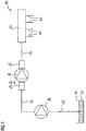
- eine schematische Übersichtsdarstellung eines Kraftstoffeinspritzsystems mit einer Kraftstoffhochdruckpumpe, an der als Einlassventil ein Magnetventil angeordnet ist;
- Fig. 2
- eine schematische Schnittdarstellung durch das Magnetventil aus
Fig. 1 in einer ersten Ausführungsform; - Fig. 3
- eine schematische Schnittdarstellung durch das Magnetventil aus
Fig. 1 in zweiten ersten Ausführungsform; - Fig. 4
- eine schematische Schnittdarstellung durch das Magnetventil aus
Fig. 1 in dritten ersten Ausführungsform; - Fig. 5
- eine schematische Schnittdarstellung durch das Magnetventil aus
Fig. 1 in einer vierten Ausführungsform; - Fig. 6
- eine schematische Schnittdarstellung durch das Magnetventil aus
Fig. 1 in einer fünften Ausführungsform; und - Fig. 7
- eine schematische Schnittdarstellung durch das Magnetventil aus
Fig. 1 in einer sechsten Ausführungsform.
- Fig. 1
- a schematic overview of a fuel injection system with a high-pressure fuel pump to which a solenoid valve is arranged as an inlet valve;
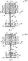
- Fig. 2
- a schematic sectional view through the solenoid valve
Fig. 1 in a first embodiment; - Fig. 3
- a schematic sectional view through the solenoid valve
Fig. 1 in the second first embodiment; - Fig. 4
- a schematic sectional view through the solenoid valve
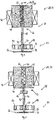
Fig. 1 in the third first embodiment; - Fig. 5
- a schematic sectional view through the solenoid valve
Fig. 1 in a fourth embodiment; - Fig. 6
- a schematic sectional view through the solenoid valve
Fig. 1 in a fifth embodiment; and - Fig. 7
- a schematic sectional view through the solenoid valve
Fig. 1 in a sixth embodiment.
Der Kraftstoff 12 wird über ein Einlassventil 24 in die Kraftstoffhochdruckpumpe 18 eingebracht, über ein Auslassventil 26 mit Druck beaufschlagt aus der Kraftstoffhochdruckpumpe 18 herausgelassen, und dem Kraftstoffhochdruckspeicher 20 zugeführt.The
Das Einlassventil 24 ist als Magnetventil 28, insbesondere als Volumenstromregelventil 30, ausgebildet, und kann somit den Fördergrad an Kraftstoff 12 in der Kraftstoffhochdruckpumpe 18 durch gezielte Variation eines Schließ- bzw. Öffnungszeitpunktes aktiv regeln.The inlet valve 24 is designed as a solenoid valve 28, in particular as a volume
Das Magnetventil 28 ist in größerem Detail jeweils in einer schematischen Schnittdarstellung in verschiedenen Ausführungsformen in den
Im Folgenden wird zunächst auf
Das Magnetventil 28 weist einen Ventilbereich 32 mit einem Schließelement 34 und einem Ventilsitz 36, sowie einen Aktuatorbereich 38 auf, der dafür sorgt, dass das Schließelement 34 entlang einer Bewegungsachse 40 bewegt werden kann.The solenoid valve 28 has a
Hierzu umfasst der Aktuatorbereich 38 einen Steuerstift 42, der mit dem Schließelement 34 gekoppelt ist. In der vorliegenden Ausführungsform geschieht diese Kopplung ohne eine feste Verbindung, sodass der Steuerstift 42 das Schließelement 34 nur berührt, wenn das Schließelement 34 bewegt werden soll.For this purpose, the
Der Steuerstift 42 wird dadurch entlang der Bewegungsachse 40 bewegt, dass er mit einem feststehenden Polstück 44 wechselwirkt, wenn eine Spule 46 ein Magnetfeld in dem Aktuatorbereich 38 induziert. Der Steuerstift 42 ist dabei gleichzeitig als Tauchanker 48 ausgebildet, und taucht in eine zentral in dem Polstück 44 angeordnete Polstückbohrung 50 ein. Durch magnetische Wechselwirkung des Tauchankers 48 und des Polstückes 44 bewegt sich der Tauchanker 48 dann entlang der Bewegungsachse 40.The
In allen in
Der Aktuatorbereich 38 weist weiter eine Rückstellfeder 62 auf, die den Steuerstift 42 in eine Ausgangsposition vorspannt, wobei in sämtlichen gezeigten Ausführungsformen die Ausgangsposition eine Öffnungsposition des Magnetventiles 28 ist. Somit ist das Magnetventil 28 in den vorliegenden Ausführungsformen als stromlos geöffnetes Magnetventil 28 ausgebildet. Es ist jedoch auch denkbar, das Magnetventil 28 als stromlos geschlossenes Magnetventil 28 auszubilden, wobei die Ausgangsposition des Steuerstiftes 42 dann so ist, dass das Plättchen 52 auf der Ventilsitzplatte 54 aufliegt.The
Es ist auch denkbar, andere Ventilformen im Ventilbereich 32 vorzusehen, das heißt statt des Plättchens 52 ein Kugelventil oder andere Formen, und dass das Schließelement 34 auch nicht gegenüberliegend des Polstückes 44 bezüglich der Ventilsitzplatte 54 angeordnet ist, sondern auf der gleichen Seite.It is also conceivable to provide other valve shapes in the
Bei bekannten Magnetventilen 28 in Kraftstoffeinspritzsystemen 10 werden normalerweise keine Tauchanker 48 verwendet, sondern der Anker ist als Blockelement gebildet und mit dem Steuerstift 42 gekoppelt.In known solenoid valves 28 in fuel injection systems 10, normally no plunger anchors 48 are used, but the armature is formed as a block element and coupled to the
Vorliegend wird jedoch nun vorgeschlagen, die Funktionen des Steuerstiftes 42 und des normalerweise vorgesehenen blockförmigen Ankers in Form eines Tauchankers 48 zu vereinen, um so Masse insbesondere an dem nun nicht mehr vorhandenen gesondert vorgesehenen Anker einzusparen.In the present case, however, it is now proposed to combine the functions of the
Insgesamt ergibt sich dabei eine geringere bewegte Masse, was dazu führt, dass Impulse beim Anschlagen in einer Endlage verringert werden, was zu einer geringeren Geräuschentwicklung führt. Zusätzlich hat dies den Vorteil, dass die Spule 46 bzw. der zugehörige Elektromagnet und auch gegebenenfalls die Rückstellfeder 62 aufgrund der geringeren wirkenden Kräfte kleiner und somit kostengünstiger ausgelegt werden können, da geringere Kräfte zur Beschleunigung nötig sind. Weiter können niedrigere Schaltzeiten als bisher erreicht werden.Overall, this results in a lower moving mass, which means that impulses are reduced when striking in an end position, resulting in a lower noise. In addition, this has the advantage that the
Die
Claims (10)
wobei der Tauchanker (48) den Steuerstift (42) bildet.A solenoid valve (28) for a fuel injection system (10) comprising
wherein the plunger armature (48) forms the control pin (42).
dadurch gekennzeichnet, dass der Ventilbereich (32) eine Ventilsitzplatte (54), die den Ventilsitz (36) bildet, aufweist, wobei das Schließelement (34) als Plättchen (52) ausgebildet ist, das in der Schließposition des Magnetventils (28) auf der Ventilsitzplatte (54) aufliegt, wobei das Polstück (44) und das Plättchen (52) insbesondere auf gegenüberliegenden Seiten der Ventilsitzplatte (54) angeordnet sind.Solenoid valve (28) according to claim 1,
characterized in that the valve portion (32) comprises a valve seat plate (54) forming the valve seat (36), the closure member (34) being formed as a plate (52) in the closed position of the solenoid valve (28) Valve seat plate (54) rests, wherein the pole piece (44) and the plate (52) are arranged in particular on opposite sides of the valve seat plate (54).
dadurch gekennzeichnet, dass der Tauchanker (48) als zylindrischer Stift ausgebildet ist, der mit einem Ventilsitzplattenende (58) berührungslos die Ventilsitzplatte (54) durchdringt.Solenoid valve (28) according to one of claims 1 or 2,
characterized in that the plunger armature (48) is designed as a cylindrical pin which penetrates the valve seat plate (54) contactlessly with a valve seat plate end (58).
dadurch gekennzeichnet, dass an dem Tauchanker (48) ein Anschlag (64) zum Begrenzen des Bewegungsweges des Tauchankers (48) entlang der Bewegungsachse (40) ausgebildet ist.Solenoid valve (28) according to one of claims 1 to 3,
characterized in that on the plunger armature (48) has a stop (64) for limiting the path of movement of the plunger armature (48) along the movement axis (40) is formed.
dadurch gekennzeichnet, dass der Anschlag (64) an einem Polstückende (56) des Tauchankers (48) zum Zusammenwirken mit dem Polstück (44) ausgebildet ist oder dass der Anschlag (64) an einem Ventilsitzplattenende (58) des Tauchankers (48) zum Zusammenwirken mit der Ventilsitzplatte (54) ausgebildet ist.Solenoid valve (28) according to claim 4,
characterized in that the stop (64) is formed on a pole piece end (56) of the plunger (48) for cooperation with the pole piece (44) or the stop (64) on a valve seat plate end (58) of the plunger rod (48) for cooperation is formed with the valve seat plate (54).
dadurch gekennzeichnet, dass in der Polstückbohrung (50) ein Anschlagsstift (66) zum Begrenzen des Bewegungsweges des Tauchankers (48) entlang der Bewegungsachse (40) angeordnet ist.Solenoid valve (28) according to one of claims 1 to 3,
characterized in that in the pole piece bore (50) a stop pin (66) for limiting the movement path of the plunger armature (48) along the movement axis (40) is arranged.
dadurch gekennzeichnet, dass eine Rückstellfeder (62) vorgesehen ist, um den Tauchanker (48) in eine Ausgangsposition vorzuspannen, wobei die Ausgangsposition vorzugsweise eine Öffnungsposition des Magnetventils (28) ist, in der der Tauchanker (48) das Schließelement (34) von dem Ventilsitz (36) weg hält.Solenoid valve (28) according to one of claims 1 to 3,
characterized in that a return spring (62) is provided for biasing the plunger armature (48) to an initial position, the initial position preferably being an opening position of the solenoid valve (28) in which the plunger armature (48) engages the closing element (34) of the solenoid Valve seat (36) holds away.
dadurch gekennzeichnet, dass die Rückstellfeder (62) innerhalb der Polstückbohrung (50) angeordnet ist oder dass die Rückstellfeder (62) außerhalb der Polstückbohrung (50) angeordnet ist und sich auf dem Anschlag (64) und an dem Polstück (44) abstützt.Solenoid valve (28) according to claim 7,
characterized in that the return spring (62) is disposed within the pole piece bore (50) or that the return spring (62) is disposed outside the pole piece bore (50) and is supported on the stopper (64) and on the pole piece (44).
dadurch gekennzeichnet, dass das Magnetventil (28) als Volumenstromregelventil (30) ausgebildet ist.Solenoid valve (28) according to one of claims 1 to 8,
characterized in that the solenoid valve (28) is designed as a flow control valve (30).
Priority Applications (5)
| Application Number | Priority Date | Filing Date | Title |
|---|---|---|---|
| EP17150743.7A EP3346121B1 (en) | 2017-01-10 | 2017-01-10 | Magnetic valve for a fuel injection system and high pressure fuel pump |
| US15/857,662 US10280888B2 (en) | 2017-01-10 | 2017-12-29 | Solenoid valve for a fuel injection system, and high pressure fuel pump |
| JP2018001338A JP2018135878A (en) | 2017-01-10 | 2018-01-09 | Electromagnetic valve for fuel injection system, and fuel high-pressure pump |
| KR1020180003015A KR102042912B1 (en) | 2017-01-10 | 2018-01-09 | Solenoid valve for a fuel injection system, and high pressure fuel pump |
| CN201810023303.3A CN108286483A (en) | 2017-01-10 | 2018-01-10 | Solenoid valve and high pressure fuel pump for fuel injection system |
Applications Claiming Priority (1)
| Application Number | Priority Date | Filing Date | Title |
|---|---|---|---|
| EP17150743.7A EP3346121B1 (en) | 2017-01-10 | 2017-01-10 | Magnetic valve for a fuel injection system and high pressure fuel pump |
Publications (2)
| Publication Number | Publication Date |
|---|---|
| EP3346121A1 true EP3346121A1 (en) | 2018-07-11 |
| EP3346121B1 EP3346121B1 (en) | 2019-09-11 |
Family
ID=57758520
Family Applications (1)
| Application Number | Title | Priority Date | Filing Date |
|---|---|---|---|
| EP17150743.7A Active EP3346121B1 (en) | 2017-01-10 | 2017-01-10 | Magnetic valve for a fuel injection system and high pressure fuel pump |
Country Status (5)
| Country | Link |
|---|---|
| US (1) | US10280888B2 (en) |
| EP (1) | EP3346121B1 (en) |
| JP (1) | JP2018135878A (en) |
| KR (1) | KR102042912B1 (en) |
| CN (1) | CN108286483A (en) |
Citations (5)
| Publication number | Priority date | Publication date | Assignee | Title |
|---|---|---|---|---|
| EP1667177A1 (en) * | 2003-09-17 | 2006-06-07 | Hitachi Powdered Metals Co., Ltd. | Sintered movable iron-core and method of manufacturing the same |
| EP2497937A1 (en) * | 2011-03-10 | 2012-09-12 | Hitachi Automotive Systems, Ltd. | Fuel injection device |
| EP2574768A1 (en) * | 2011-09-27 | 2013-04-03 | Hitachi Automotive Systems, Ltd. | Fuel injector |
| EP2653712A1 (en) * | 2012-04-16 | 2013-10-23 | Robert Bosch GmbH | Fuel injector with a solenoid valve |
| WO2016055267A1 (en) * | 2014-10-07 | 2016-04-14 | Robert Bosch Gmbh | Proportional valve that can be actuated electromagnetically |
Family Cites Families (11)
| Publication number | Priority date | Publication date | Assignee | Title |
|---|---|---|---|---|
| JPH10306761A (en) | 1997-05-07 | 1998-11-17 | Denso Corp | Solenoid valve used for high pressure fuel pump |
| DE102010022536A1 (en) * | 2010-06-02 | 2011-12-08 | Continental Automotive Gmbh | Method and device for controlling a valve |
| DE102010061810A1 (en) * | 2010-11-23 | 2012-05-24 | Robert Bosch Gmbh | Method for operating a fuel system of an internal combustion engine |
| DE102011089360A1 (en) | 2011-12-21 | 2013-06-27 | Robert Bosch Gmbh | Fuel injection valve for internal combustion engines |
| DE112014000901T5 (en) * | 2013-03-19 | 2015-11-26 | Hitachi Automotive Systems, Ltd. | High-pressure fuel supply pump |
| DE102013206674A1 (en) * | 2013-04-15 | 2014-10-16 | Robert Bosch Gmbh | Method and device for controlling a quantity control valve |
| DE102013210036A1 (en) * | 2013-05-29 | 2014-12-04 | Robert Bosch Gmbh | High pressure pump for a fuel injection system |
| JP2015108409A (en) | 2013-12-05 | 2015-06-11 | 日立オートモティブシステムズ株式会社 | Solenoid valve |
| JP2015218675A (en) | 2014-05-20 | 2015-12-07 | 日立オートモティブシステムズ株式会社 | High-pressure fuel supply pump |
| JP2016142143A (en) | 2015-01-30 | 2016-08-08 | 日立オートモティブシステムズ株式会社 | High pressure fuel supply pump |
| US9777879B2 (en) * | 2015-07-20 | 2017-10-03 | Delphi Technologies, Inc. | Pulsation damper |
-
2017
- 2017-01-10 EP EP17150743.7A patent/EP3346121B1/en active Active
- 2017-12-29 US US15/857,662 patent/US10280888B2/en active Active
-
2018
- 2018-01-09 KR KR1020180003015A patent/KR102042912B1/en active IP Right Grant
- 2018-01-09 JP JP2018001338A patent/JP2018135878A/en active Pending
- 2018-01-10 CN CN201810023303.3A patent/CN108286483A/en active Pending
Patent Citations (5)
| Publication number | Priority date | Publication date | Assignee | Title |
|---|---|---|---|---|
| EP1667177A1 (en) * | 2003-09-17 | 2006-06-07 | Hitachi Powdered Metals Co., Ltd. | Sintered movable iron-core and method of manufacturing the same |
| EP2497937A1 (en) * | 2011-03-10 | 2012-09-12 | Hitachi Automotive Systems, Ltd. | Fuel injection device |
| EP2574768A1 (en) * | 2011-09-27 | 2013-04-03 | Hitachi Automotive Systems, Ltd. | Fuel injector |
| EP2653712A1 (en) * | 2012-04-16 | 2013-10-23 | Robert Bosch GmbH | Fuel injector with a solenoid valve |
| WO2016055267A1 (en) * | 2014-10-07 | 2016-04-14 | Robert Bosch Gmbh | Proportional valve that can be actuated electromagnetically |
Also Published As
| Publication number | Publication date |
|---|---|
| US20180195481A1 (en) | 2018-07-12 |
| JP2018135878A (en) | 2018-08-30 |
| US10280888B2 (en) | 2019-05-07 |
| KR102042912B1 (en) | 2019-11-08 |
| KR20180082354A (en) | 2018-07-18 |
| EP3346121B1 (en) | 2019-09-11 |
| CN108286483A (en) | 2018-07-17 |
Similar Documents
| Publication | Publication Date | Title |
|---|---|---|
| EP2634412B1 (en) | Injection valve | |
| DE10001828A1 (en) | Direct-control fuel injection device for combustion engine has valve body with actuator to move it in opening direction to let fuel flow from high pressure channel to connecting channel | |
| DE19650865A1 (en) | magnetic valve | |
| DE10100422A1 (en) | Solenoid valve for controlling an injection valve of an internal combustion engine | |
| DE10121892A1 (en) | Fuel injection valve for internal combustion engines | |
| EP3478957B1 (en) | Valve for injecting gaseous fuel | |
| EP1203151B1 (en) | Two-stage electromagnetic valve for an injector of internal combustion engines | |
| DE60125304T2 (en) | ADJUSTABLE LIFTING DEVICE FOR A FUEL INJECTION VALVE | |
| EP2914842B1 (en) | Actuator | |
| DE102016220326A1 (en) | Valve for metering a gaseous or liquid fuel | |
| EP3364015B1 (en) | Electromagnetic switching valve and high-pressure fuel pump | |
| EP1317618A1 (en) | Valve for controlling liquids | |
| EP2462335B1 (en) | Device for high-pressure fuel injection | |
| DE102014220877B3 (en) | Fuel injection valve | |
| DE102012012480A1 (en) | Common rail fuel injector for use in internal combustion engine, has check needle including opening hydraulic surface exposed to fluid pressure of nozzle supply passage and closing hydraulic surface exposed to fluid pressure of chamber | |
| EP3346121B1 (en) | Magnetic valve for a fuel injection system and high pressure fuel pump | |
| EP0793004B1 (en) | Electromagnetic valve control | |
| EP1404965A1 (en) | Control valve for liquids | |
| EP1967727A2 (en) | Fuel injector with improved implementation of a control valve for controlling an injection needle | |
| EP3361085B1 (en) | Electromagnetic switching valve and high-pressure fuel pump | |
| DE102015209553B3 (en) | Electromagnetic switching valve device | |
| DE102012201413A1 (en) | Magnetic valve i.e. fast-switching magnetic valve, for common-rail injector for injecting fuel into combustion chamber of internal combustion engine, has damping chamber engaged with locating surface for creating excess stroke impact | |
| DE102008042531A1 (en) | Valve arrangement for fuel high pressure injection, comprises electromagnets, anchor, sliding sleeve and housing provided with spraying holes, where interior element divides interior space of housing | |
| DE19936943A1 (en) | Fuel injection valve for internal combustion engine, in which valve closing body is partly spherical | |
| DE2131841C3 (en) | Device for controlling fuel injection in internal combustion engines |
Legal Events
| Date | Code | Title | Description |
|---|---|---|---|
| PUAI | Public reference made under article 153(3) epc to a published international application that has entered the european phase |
Free format text: ORIGINAL CODE: 0009012 |
|
| STAA | Information on the status of an ep patent application or granted ep patent |
Free format text: STATUS: THE APPLICATION HAS BEEN PUBLISHED |
|
| AK | Designated contracting states |
Kind code of ref document: A1 Designated state(s): AL AT BE BG CH CY CZ DE DK EE ES FI FR GB GR HR HU IE IS IT LI LT LU LV MC MK MT NL NO PL PT RO RS SE SI SK SM TR |
|
| AX | Request for extension of the european patent |
Extension state: BA ME |
|
| STAA | Information on the status of an ep patent application or granted ep patent |
Free format text: STATUS: REQUEST FOR EXAMINATION WAS MADE |
|
| 17P | Request for examination filed |
Effective date: 20190111 |
|
| RBV | Designated contracting states (corrected) |
Designated state(s): AL AT BE BG CH CY CZ DE DK EE ES FI FR GB GR HR HU IE IS IT LI LT LU LV MC MK MT NL NO PL PT RO RS SE SI SK SM TR |
|
| GRAP | Despatch of communication of intention to grant a patent |
Free format text: ORIGINAL CODE: EPIDOSNIGR1 |
|
| STAA | Information on the status of an ep patent application or granted ep patent |
Free format text: STATUS: GRANT OF PATENT IS INTENDED |
|
| RIC1 | Information provided on ipc code assigned before grant |
Ipc: F02M 63/00 20060101ALI20190207BHEP Ipc: F02M 51/06 20060101AFI20190207BHEP |
|
| INTG | Intention to grant announced |
Effective date: 20190312 |
|
| GRAJ | Information related to disapproval of communication of intention to grant by the applicant or resumption of examination proceedings by the epo deleted |
Free format text: ORIGINAL CODE: EPIDOSDIGR1 |
|
| STAA | Information on the status of an ep patent application or granted ep patent |
Free format text: STATUS: REQUEST FOR EXAMINATION WAS MADE |
|
| INTC | Intention to grant announced (deleted) | ||
| GRAP | Despatch of communication of intention to grant a patent |
Free format text: ORIGINAL CODE: EPIDOSNIGR1 |
|
| STAA | Information on the status of an ep patent application or granted ep patent |
Free format text: STATUS: GRANT OF PATENT IS INTENDED |
|
| INTG | Intention to grant announced |
Effective date: 20190618 |
|
| GRAS | Grant fee paid |
Free format text: ORIGINAL CODE: EPIDOSNIGR3 |
|
| GRAA | (expected) grant |
Free format text: ORIGINAL CODE: 0009210 |
|
| STAA | Information on the status of an ep patent application or granted ep patent |
Free format text: STATUS: THE PATENT HAS BEEN GRANTED |
|
| AK | Designated contracting states |
Kind code of ref document: B1 Designated state(s): AL AT BE BG CH CY CZ DE DK EE ES FI FR GB GR HR HU IE IS IT LI LT LU LV MC MK MT NL NO PL PT RO RS SE SI SK SM TR |
|
| REG | Reference to a national code |
Ref country code: GB Ref legal event code: FG4D Free format text: NOT ENGLISH |
|
| REG | Reference to a national code |
Ref country code: CH Ref legal event code: EP |
|
| REG | Reference to a national code |
Ref country code: AT Ref legal event code: REF Ref document number: 1178769 Country of ref document: AT Kind code of ref document: T Effective date: 20190915 |
|
| REG | Reference to a national code |
Ref country code: DE Ref legal event code: R096 Ref document number: 502017002235 Country of ref document: DE Ref country code: IE Ref legal event code: FG4D Free format text: LANGUAGE OF EP DOCUMENT: GERMAN |
|
| REG | Reference to a national code |
Ref country code: NL Ref legal event code: MP Effective date: 20190911 |
|
| REG | Reference to a national code |
Ref country code: LT Ref legal event code: MG4D |
|
| PG25 | Lapsed in a contracting state [announced via postgrant information from national office to epo] |
Ref country code: NO Free format text: LAPSE BECAUSE OF FAILURE TO SUBMIT A TRANSLATION OF THE DESCRIPTION OR TO PAY THE FEE WITHIN THE PRESCRIBED TIME-LIMIT Effective date: 20191211 Ref country code: FI Free format text: LAPSE BECAUSE OF FAILURE TO SUBMIT A TRANSLATION OF THE DESCRIPTION OR TO PAY THE FEE WITHIN THE PRESCRIBED TIME-LIMIT Effective date: 20190911 Ref country code: SE Free format text: LAPSE BECAUSE OF FAILURE TO SUBMIT A TRANSLATION OF THE DESCRIPTION OR TO PAY THE FEE WITHIN THE PRESCRIBED TIME-LIMIT Effective date: 20190911 Ref country code: HR Free format text: LAPSE BECAUSE OF FAILURE TO SUBMIT A TRANSLATION OF THE DESCRIPTION OR TO PAY THE FEE WITHIN THE PRESCRIBED TIME-LIMIT Effective date: 20190911 Ref country code: LT Free format text: LAPSE BECAUSE OF FAILURE TO SUBMIT A TRANSLATION OF THE DESCRIPTION OR TO PAY THE FEE WITHIN THE PRESCRIBED TIME-LIMIT Effective date: 20190911 Ref country code: BG Free format text: LAPSE BECAUSE OF FAILURE TO SUBMIT A TRANSLATION OF THE DESCRIPTION OR TO PAY THE FEE WITHIN THE PRESCRIBED TIME-LIMIT Effective date: 20191211 |
|
| PG25 | Lapsed in a contracting state [announced via postgrant information from national office to epo] |
Ref country code: LV Free format text: LAPSE BECAUSE OF FAILURE TO SUBMIT A TRANSLATION OF THE DESCRIPTION OR TO PAY THE FEE WITHIN THE PRESCRIBED TIME-LIMIT Effective date: 20190911 Ref country code: AL Free format text: LAPSE BECAUSE OF FAILURE TO SUBMIT A TRANSLATION OF THE DESCRIPTION OR TO PAY THE FEE WITHIN THE PRESCRIBED TIME-LIMIT Effective date: 20190911 Ref country code: GR Free format text: LAPSE BECAUSE OF FAILURE TO SUBMIT A TRANSLATION OF THE DESCRIPTION OR TO PAY THE FEE WITHIN THE PRESCRIBED TIME-LIMIT Effective date: 20191212 Ref country code: RS Free format text: LAPSE BECAUSE OF FAILURE TO SUBMIT A TRANSLATION OF THE DESCRIPTION OR TO PAY THE FEE WITHIN THE PRESCRIBED TIME-LIMIT Effective date: 20190911 Ref country code: ES Free format text: LAPSE BECAUSE OF FAILURE TO SUBMIT A TRANSLATION OF THE DESCRIPTION OR TO PAY THE FEE WITHIN THE PRESCRIBED TIME-LIMIT Effective date: 20190911 |
|
| PG25 | Lapsed in a contracting state [announced via postgrant information from national office to epo] |
Ref country code: PL Free format text: LAPSE BECAUSE OF FAILURE TO SUBMIT A TRANSLATION OF THE DESCRIPTION OR TO PAY THE FEE WITHIN THE PRESCRIBED TIME-LIMIT Effective date: 20190911 Ref country code: PT Free format text: LAPSE BECAUSE OF FAILURE TO SUBMIT A TRANSLATION OF THE DESCRIPTION OR TO PAY THE FEE WITHIN THE PRESCRIBED TIME-LIMIT Effective date: 20200113 Ref country code: NL Free format text: LAPSE BECAUSE OF FAILURE TO SUBMIT A TRANSLATION OF THE DESCRIPTION OR TO PAY THE FEE WITHIN THE PRESCRIBED TIME-LIMIT Effective date: 20190911 Ref country code: EE Free format text: LAPSE BECAUSE OF FAILURE TO SUBMIT A TRANSLATION OF THE DESCRIPTION OR TO PAY THE FEE WITHIN THE PRESCRIBED TIME-LIMIT Effective date: 20190911 Ref country code: IT Free format text: LAPSE BECAUSE OF FAILURE TO SUBMIT A TRANSLATION OF THE DESCRIPTION OR TO PAY THE FEE WITHIN THE PRESCRIBED TIME-LIMIT Effective date: 20190911 Ref country code: RO Free format text: LAPSE BECAUSE OF FAILURE TO SUBMIT A TRANSLATION OF THE DESCRIPTION OR TO PAY THE FEE WITHIN THE PRESCRIBED TIME-LIMIT Effective date: 20190911 |
|
| RAP2 | Party data changed (patent owner data changed or rights of a patent transferred) |
Owner name: VITESCO TECHNOLOGIES GMBH |
|
| PG25 | Lapsed in a contracting state [announced via postgrant information from national office to epo] |
Ref country code: SM Free format text: LAPSE BECAUSE OF FAILURE TO SUBMIT A TRANSLATION OF THE DESCRIPTION OR TO PAY THE FEE WITHIN THE PRESCRIBED TIME-LIMIT Effective date: 20190911 Ref country code: IS Free format text: LAPSE BECAUSE OF FAILURE TO SUBMIT A TRANSLATION OF THE DESCRIPTION OR TO PAY THE FEE WITHIN THE PRESCRIBED TIME-LIMIT Effective date: 20200224 Ref country code: SK Free format text: LAPSE BECAUSE OF FAILURE TO SUBMIT A TRANSLATION OF THE DESCRIPTION OR TO PAY THE FEE WITHIN THE PRESCRIBED TIME-LIMIT Effective date: 20190911 Ref country code: CZ Free format text: LAPSE BECAUSE OF FAILURE TO SUBMIT A TRANSLATION OF THE DESCRIPTION OR TO PAY THE FEE WITHIN THE PRESCRIBED TIME-LIMIT Effective date: 20190911 |
|
| REG | Reference to a national code |
Ref country code: DE Ref legal event code: R081 Ref document number: 502017002235 Country of ref document: DE Owner name: VITESCO TECHNOLOGIES GMBH, DE Free format text: FORMER OWNER: CONTINENTAL AUTOMOTIVE GMBH, 30165 HANNOVER, DE |
|
| REG | Reference to a national code |
Ref country code: DE Ref legal event code: R097 Ref document number: 502017002235 Country of ref document: DE |
|
| PGFP | Annual fee paid to national office [announced via postgrant information from national office to epo] |
Ref country code: FR Payment date: 20200121 Year of fee payment: 4 |
|
| PLBE | No opposition filed within time limit |
Free format text: ORIGINAL CODE: 0009261 |
|
| STAA | Information on the status of an ep patent application or granted ep patent |
Free format text: STATUS: NO OPPOSITION FILED WITHIN TIME LIMIT |
|
| PG2D | Information on lapse in contracting state deleted |
Ref country code: IS |
|
| PG25 | Lapsed in a contracting state [announced via postgrant information from national office to epo] |
Ref country code: IS Free format text: LAPSE BECAUSE OF FAILURE TO SUBMIT A TRANSLATION OF THE DESCRIPTION OR TO PAY THE FEE WITHIN THE PRESCRIBED TIME-LIMIT Effective date: 20200112 Ref country code: DK Free format text: LAPSE BECAUSE OF FAILURE TO SUBMIT A TRANSLATION OF THE DESCRIPTION OR TO PAY THE FEE WITHIN THE PRESCRIBED TIME-LIMIT Effective date: 20190911 |
|
| 26N | No opposition filed |
Effective date: 20200615 |
|
| PG25 | Lapsed in a contracting state [announced via postgrant information from national office to epo] |
Ref country code: SI Free format text: LAPSE BECAUSE OF FAILURE TO SUBMIT A TRANSLATION OF THE DESCRIPTION OR TO PAY THE FEE WITHIN THE PRESCRIBED TIME-LIMIT Effective date: 20190911 Ref country code: MC Free format text: LAPSE BECAUSE OF FAILURE TO SUBMIT A TRANSLATION OF THE DESCRIPTION OR TO PAY THE FEE WITHIN THE PRESCRIBED TIME-LIMIT Effective date: 20190911 |
|
| REG | Reference to a national code |
Ref country code: CH Ref legal event code: PL |
|
| REG | Reference to a national code |
Ref country code: BE Ref legal event code: MM Effective date: 20200131 |
|
| PG25 | Lapsed in a contracting state [announced via postgrant information from national office to epo] |
Ref country code: LU Free format text: LAPSE BECAUSE OF NON-PAYMENT OF DUE FEES Effective date: 20200110 |
|
| PG25 | Lapsed in a contracting state [announced via postgrant information from national office to epo] |
Ref country code: CH Free format text: LAPSE BECAUSE OF NON-PAYMENT OF DUE FEES Effective date: 20200131 Ref country code: LI Free format text: LAPSE BECAUSE OF NON-PAYMENT OF DUE FEES Effective date: 20200131 Ref country code: BE Free format text: LAPSE BECAUSE OF NON-PAYMENT OF DUE FEES Effective date: 20200131 |
|
| PG25 | Lapsed in a contracting state [announced via postgrant information from national office to epo] |
Ref country code: IE Free format text: LAPSE BECAUSE OF NON-PAYMENT OF DUE FEES Effective date: 20200110 |
|
| GBPC | Gb: european patent ceased through non-payment of renewal fee |
Effective date: 20210110 |
|
| PG25 | Lapsed in a contracting state [announced via postgrant information from national office to epo] |
Ref country code: FR Free format text: LAPSE BECAUSE OF NON-PAYMENT OF DUE FEES Effective date: 20210131 |
|
| PG25 | Lapsed in a contracting state [announced via postgrant information from national office to epo] |
Ref country code: GB Free format text: LAPSE BECAUSE OF NON-PAYMENT OF DUE FEES Effective date: 20210110 |
|
| REG | Reference to a national code |
Ref country code: DE Ref legal event code: R081 Ref document number: 502017002235 Country of ref document: DE Owner name: VITESCO TECHNOLOGIES GMBH, DE Free format text: FORMER OWNER: VITESCO TECHNOLOGIES GMBH, 30165 HANNOVER, DE |
|
| PG25 | Lapsed in a contracting state [announced via postgrant information from national office to epo] |
Ref country code: TR Free format text: LAPSE BECAUSE OF FAILURE TO SUBMIT A TRANSLATION OF THE DESCRIPTION OR TO PAY THE FEE WITHIN THE PRESCRIBED TIME-LIMIT Effective date: 20190911 Ref country code: MT Free format text: LAPSE BECAUSE OF FAILURE TO SUBMIT A TRANSLATION OF THE DESCRIPTION OR TO PAY THE FEE WITHIN THE PRESCRIBED TIME-LIMIT Effective date: 20190911 Ref country code: CY Free format text: LAPSE BECAUSE OF FAILURE TO SUBMIT A TRANSLATION OF THE DESCRIPTION OR TO PAY THE FEE WITHIN THE PRESCRIBED TIME-LIMIT Effective date: 20190911 |
|
| PG25 | Lapsed in a contracting state [announced via postgrant information from national office to epo] |
Ref country code: MK Free format text: LAPSE BECAUSE OF FAILURE TO SUBMIT A TRANSLATION OF THE DESCRIPTION OR TO PAY THE FEE WITHIN THE PRESCRIBED TIME-LIMIT Effective date: 20190911 |
|
| REG | Reference to a national code |
Ref country code: AT Ref legal event code: MM01 Ref document number: 1178769 Country of ref document: AT Kind code of ref document: T Effective date: 20220110 |
|
| PG25 | Lapsed in a contracting state [announced via postgrant information from national office to epo] |
Ref country code: AT Free format text: LAPSE BECAUSE OF NON-PAYMENT OF DUE FEES Effective date: 20220110 |
|
| P01 | Opt-out of the competence of the unified patent court (upc) registered |
Effective date: 20230530 |
|
| PGFP | Annual fee paid to national office [announced via postgrant information from national office to epo] |
Ref country code: DE Payment date: 20240131 Year of fee payment: 8 |