EP3346046A1 - High efficiency vented clothes dryer having heat pump system - Google Patents
High efficiency vented clothes dryer having heat pump system Download PDFInfo
- Publication number
- EP3346046A1 EP3346046A1 EP16840710.4A EP16840710A EP3346046A1 EP 3346046 A1 EP3346046 A1 EP 3346046A1 EP 16840710 A EP16840710 A EP 16840710A EP 3346046 A1 EP3346046 A1 EP 3346046A1
- Authority
- EP
- European Patent Office
- Prior art keywords
- air
- evaporator
- heat pump
- pump system
- dryer
- Prior art date
- Legal status (The legal status is an assumption and is not a legal conclusion. Google has not performed a legal analysis and makes no representation as to the accuracy of the status listed.)
- Granted
Links
Images


Classifications
-
- D—TEXTILES; PAPER
- D06—TREATMENT OF TEXTILES OR THE LIKE; LAUNDERING; FLEXIBLE MATERIALS NOT OTHERWISE PROVIDED FOR
- D06F—LAUNDERING, DRYING, IRONING, PRESSING OR FOLDING TEXTILE ARTICLES
- D06F58/00—Domestic laundry dryers
- D06F58/20—General details of domestic laundry dryers
- D06F58/206—Heat pump arrangements
-
- D—TEXTILES; PAPER
- D06—TREATMENT OF TEXTILES OR THE LIKE; LAUNDERING; FLEXIBLE MATERIALS NOT OTHERWISE PROVIDED FOR
- D06F—LAUNDERING, DRYING, IRONING, PRESSING OR FOLDING TEXTILE ARTICLES
- D06F58/00—Domestic laundry dryers
- D06F58/20—General details of domestic laundry dryers
- D06F58/24—Condensing arrangements
-
- D—TEXTILES; PAPER
- D06—TREATMENT OF TEXTILES OR THE LIKE; LAUNDERING; FLEXIBLE MATERIALS NOT OTHERWISE PROVIDED FOR
- D06F—LAUNDERING, DRYING, IRONING, PRESSING OR FOLDING TEXTILE ARTICLES
- D06F2103/00—Parameters monitored or detected for the control of domestic laundry washing machines, washer-dryers or laundry dryers
- D06F2103/50—Parameters monitored or detected for the control of domestic laundry washing machines, washer-dryers or laundry dryers related to heat pumps, e.g. pressure or flow rate
-
- D—TEXTILES; PAPER
- D06—TREATMENT OF TEXTILES OR THE LIKE; LAUNDERING; FLEXIBLE MATERIALS NOT OTHERWISE PROVIDED FOR
- D06F—LAUNDERING, DRYING, IRONING, PRESSING OR FOLDING TEXTILE ARTICLES
- D06F2103/00—Parameters monitored or detected for the control of domestic laundry washing machines, washer-dryers or laundry dryers
- D06F2103/56—Parameters monitored or detected for the control of domestic laundry washing machines, washer-dryers or laundry dryers related to air ducts, e.g. position of flow diverters
-
- D—TEXTILES; PAPER
- D06—TREATMENT OF TEXTILES OR THE LIKE; LAUNDERING; FLEXIBLE MATERIALS NOT OTHERWISE PROVIDED FOR
- D06F—LAUNDERING, DRYING, IRONING, PRESSING OR FOLDING TEXTILE ARTICLES
- D06F2105/00—Systems or parameters controlled or affected by the control systems of washing machines, washer-dryers or laundry dryers
- D06F2105/26—Heat pumps
-
- D—TEXTILES; PAPER
- D06—TREATMENT OF TEXTILES OR THE LIKE; LAUNDERING; FLEXIBLE MATERIALS NOT OTHERWISE PROVIDED FOR
- D06F—LAUNDERING, DRYING, IRONING, PRESSING OR FOLDING TEXTILE ARTICLES
- D06F58/00—Domestic laundry dryers
- D06F58/10—Drying cabinets or drying chambers having heating or ventilating means
Definitions
- the present disclosure relates to a clothes drying apparatus in the field of the household appliances, in particular, relates to a high efficiency vented dryer having a heat pump system.
- the existing dryer mainly comprises two following ways: The first one is a heat pump dryer, and its working principle is as follows: the outer drum is connected with both end of the drying air duct to form a circulating air pathway.
- the air stream in the drying air duct is heated by the condenser of the heat pump system and becomes hot dry air, and then is introduced into the outer drum.
- the hot dry air introduced into the outer drum gasifies the moisture of the clothes therein.
- the gasified moisture is mixed into the air and the air becomes hot moist air, and then the hot moist air is exhausted from the outer drum and introduced into the drying air duct.
- the moisture is condensed from the hot moist air introduced into the drying air duct by the evaporator, and then the hot moist air becomes the low-temperature dry air.
- the low-temperature dry air flows through the evaporator again, to complete the circulation of air stream.
- the second one is an air vented dryer, and its working principles is as follows: the dryer draws air from the surrounding area, heats the air by using the heating wire, then the heated high-temperature dry air is blown into the outer drum, and the moisture of the clothes therein is vaporized. The vaporized moisture is mixed into the air and the air becomes hot moist air. The hot moist air is exhausted from the outer drum eventually to realizing the purposes of drying the clothes. However, since the exhaust air contains a large amount of waste heat in the above manner, it cannot be recycled, resulting in large energy consumption and low efficiency.
- a vented dryer having a heat pump system is proposed.
- the vented dryer is provided with a heat pump system, and recycles the heat in the exhaust air using the evaporator of the heat pump system, transfers the collected heat to the condenser of the heat pump system, and heats the intake air of the dryer using the condenser.
- the vented dryer adopting the above methods consumes a large amount of energy, and the heat absorption of the refrigerant medium in the heat pump system cannot reach the saturation point, resulting in a relatively low drying speed. Therefore, how to provide a vented heat pump dryer with a relatively high drying speed and an energy-saving effect becomes a research and development hotspot of the manufactures.
- the first object of the present invention is to provide a high efficiency dryer having a heat pump system to realize the purpose of simultaneously recycling the heat in the exhaust air and the external air by the heat pump system of the dryer.
- the second object is to provide a dryer to achieves the purpose of dehumidifying the external environment where the dryer is located.
- a high efficiency vented dryer having a heat pump system comprising: an outer drum, an air-intake drying air duct and an air-exhaust drying air duct for allowing the outer drum communicating with outside respectively, wherein the dryer is further provided with a heat pump system, the heat pump system comprises a first evaporator and a second evaporator arranged in parallel or in series. The first evaporator is arranged in the air-exhaust drying air duct and the second evaporator is arranged in an external atmosphere so as to absorb heat from the exhaust air and the outside respectively.
- an air-intake end and an air-out end of the first evaporator and the second evaporator are respectively provided with a control valve for controlling on-off, so that the refrigerant medium in the heat pump system flows through the first evaporator and the second evaporator independently or at the same time.
- the air-intake end of the first evaporator and the air-intake end of the second evaporator are respectively communicated with an air-out end of a throttling device of the heat pump system through a first three-way control valve.
- the air-out end of the first evaporator and an air-out end of the second evaporator are respectively communicated with the air-out end of a compressor of the heat pump system through a second three-way control valve.
- the air-out end of the first evaporator is respectively communicated with the air-intake end of the second evaporator and the air-intake end of the compressor of the heat pump system through a third three-way control valve.
- the air-out end of the second evaporator is communicated with the air-intake end of the compressor of the heat pump system through a one-way valve.
- the heat pump system is in a first state in which the refrigerant medium only flows through the first evaporator without flowing through the second evaporator.
- the heat pump system is in a second state in which the refrigerant medium simultaneously flows through the first evaporator and the second evaporator.
- a condenser of the heat pump system is arranged in the air-intake drying air duct.
- An air-intake end of the condenser is communicated with the air-out end of the compressor of the heat pump system, and the air-out end of the condenser is communicated with the air-intake end of the throttling device of the heat pump system.
- the compressor of the heat pump system is arranged in the air-intake drying air duct located upstream from the condenser to preheat the intake air stream.
- the air-intake drying air duct is provided with an auxiliary heating wire, and the auxiliary heating wire is located downstream from the condenser.
- the air-exhaust drying air duct is provided with a fan controlling the flow direction of the air stream, and the fan is located upstream from the first evaporator.
- a second fan is arranged outside the air-exhaust drying air duct and is close to the air inlet of the second evaporator so as to provide an acting force to the air at the second evaporator. It enables that an airflow flows through the second evaporator.
- a high efficiency vented dryer having a heat pump system comprising: an outer drum, an air-intake drying air duct and an air-exhaust drying air duct for communicating the outer drum (1) with outside (3) respectively.
- the dryer is further provided with a heat pump system.
- the evaporator of the heat pump system crosses the air-exhaust drying air duct, so that a first portion of the evaporator (5) is located in the air-exhaust drying air duct while a second portion of the evaporator (5) is located in the outside.
- the present disclosure has the following advantages compared with the prior art.
- the heat pump system can simultaneously or independently absorb heat from the air exhausted by the dryer and the ambient air of the dryer to heat the intake air by using heat in the exhaust air and heat in the environment, so as to improve drying rate of the dryer.
- the dryer of the present invention can respectively execute different working states at the earlier stage and later stage of the drying process to improve the heat absorption saturation of the refrigerant medium and improve the working efficiency of the heat pump system.
- the second evaporator also condenses and collects the water vapor from the air in the environment so as to achieve the purpose of dehumidifying the air in the environment by the dryer.
- the structure of the present disclosure is simple, the method is concise, and the effect is remarkable. It is suitable for promotion.
- a vented dryer having a heat pump system comprises an outer drum 1, an air-intake drying air duct 2, and an air-exhaust drying air duct 3.
- One end of the air-intake drying air duct 2 is communicated with air inlet of the outer drum, and another end is an air-intake end 20 which is communicated with the atmosphere.
- One end of the air-exhaust drying air duct 3 is communicated with the air outlet 23 of the outer drum, and another end is an air-out end 21 which is communicated with the atmosphere.
- the dryer is further provided with a heat pump system.
- the heat pump system at least comprising the condensers 4, a throttling device 10, an evaporator 5 and a compressor 9, which are sequentially connected end to end via a pipeline to from a flow channel for circulating the refrigerant.
- a condenser is arranged in the air-intake drying air duct 2, and an evaporator 5 is arranged in the air-exhaust drying air duct 3.
- An outlet end of the compressor 9 is an end for allowing the refrigerant to flow out from the compressor, and this outlet end is connected with the condenser 4 through the pipeline.
- An inlet end of the compressor 9 is the end for allowing the refrigerant to flow into the compressor, and this inlet end is connected with the evaporator 4 through the pipeline.
- the refrigerant medium in the heat pump system circulates in the direction from the outlet end of the compressor to the condenser, the throttling device, the evaporator, and to the inlet end of the compressor. It achieves the purposes of heating the intake air stream which flows through the condenser, and cooling the exhaust air stream which flows through the evaporator, and then achieves the purpose of drying the clothes inside the outer drum.
- the compressor 9 is arranged in the air-intake drying air duct 2 located upstream from the condenser 4 to preheat the intake air stream by using the heat radiation during the operation of the compressor.
- the air-intake drying air duct 2 is provided with an auxiliary heating wire 6 for electrically heating the air stream passing through. Further and preferably, the auxiliary heating wire 6 is arranged in the air-exhaust drying air duct 2 located downstream from the condenser 4, to improve the electric heating efficiency.
- the air intake drying air duct and/or the air-exhaust drying air duct is provided with a fan 8 for controlling the air stream direction in the air passage.
- the fan 8 is only arranged in the air-exhaust drying air duct 3 and located upstream from the evaporator 5. So that the air stream in the air-intake drying air duct 2 flows from the air-intake end 20 to the air inlet 22, and the air stream in the outer drum 1 flows from the air inlet 22 to the air outlet 23, and the air stream in the air-exhaust drying air duct 3 flows from the air outlet 23 to the air-out end 21.
- the air-exhaust drying air duct 3 is provided with a filter net 7 for filtering the threads in the exhaust air stream.
- the filter net 7 is arranged in the air-exhaust drying air duct 3 and located upstream from the fan 8 and close to the air outlet 23.
- a high efficiency vented dryer having a heat pump system is provided in the embodiment of the present disclosure.
- the heat pump system of the dryer is provided with a first evaporator 15 and a second evaporator 16 arranged in parallel or in series.
- the first evaporator 15 is arranged in the air-exhaust drying air duct 3 and the second evaporator 16 is arranged in an external atmosphere.
- the heat pump system can simultaneously or independently absorb heat from the air exhausted by the dryer and the ambient air of the dryer to heat the intake air by using heat in the exhaust air and heat in the environment, so as to improve drying rate of the dryer. Meanwhile, during the process of absorbing heat from the air in the environment, the second evaporator also condenses and collects the water vapor from the air in the environment so as to achieve the purpose of dehumidifying the air in the environment by the dryer.
- a second fan 19 is arranged outside the air-exhaust drying air duct 3 and is close to the air inlet of the second evaporator 16, so as to provide an acting force to the air at the second evaporator. It enables that an airflow flows through the second evaporator.
- the air-intake end of the first evaporator 15 and the air-intake end of the second evaporator 16 are respectively communicated with the throttling device 10 of the heat pump system through a first three-way control valve 11.
- the air-out end of the first evaporator 15 and the air-out end of the second evaporator 16 are respectively communicated with the air-intake end of the compressor 9 of the heat pump system through a second three-way control valve 12. So that the first evaporator 15 and the second evaporator 16 are arranged in parallel and then are connected to the heat pump system.
- the three-way control valves are respectively arranged at the air-intake end and the air-out end of the first evaporator 15 and the second evaporator 16 arranged in parallel so as to control the flow direction of the refrigerant medium. So that realizes the purpose that the first evaporator 15 and the second evaporator 16 can simultaneously or separately absorb heat by using the refrigerant medium flowing through them.
- the heat pump when the dryer is at different working stages, the heat pump is correspondingly in different states to improve the heat absorption saturation of the refrigerant medium and improve the working efficiency of the heat pump system.
- Specific implementations are as follows: At the later stage of the drying process of the dryer, the heat pump system is in the first state.
- the first three-way control valve 11 is only communicated with the air-intake end of the first evaporator 15 and the air-out end of the throttling device
- the second three-way control valve 12 is only communicated with the air-out end of the first evaporator 15 and the air-intake end of the compressor. It allows the refrigerant medium to only flow through the first evaporator 15, without flowing through the second evaporator 16. So that the heat pump system only uses the first evaporator 15 to absorb heat from the exhaust air.
- the heat pump system is in the second state.
- the first three-way control valve 11 simultaneously communicates the air-intake end of the evaporator 15 and the air-intake end of the second evaporator 16 to the air-out end of the throttling device 10.
- the second three-way control valve 12 simultaneously communicates the air-out end of the first evaporator 15 and the air-out end of the second evaporator 16 to the air-intake end of the compressor 9. It allows the refrigerant medium to simultaneously flow through the first evaporator 15 and the second evaporator 16. So that the heat pump system can use the first evaporator 15 to absorb heat from the exhaust air and use the second evaporator 16 to absorb heat from the air in the environment, simultaneously.
- the air-out end of the first evaporator 15 is respectively communicated with the air-intake end of the second evaporator 16 and the air-intake end of the compressor 9 of the heat pump system through the third three-way control valve 17.
- the air-out end of the second evaporator 16 is communicated with the air-intake end of the compressor 9 through a one-way valve 18.
- the flow direction of the refrigerant medium in the one-way valve 18 is from the second evaporator 16 to the compressor 9, so that the first evaporator 15 and the second evaporator 16 are arranged in series and then are connected to the heat pump system.
- the corresponding control valves are respectively arranged at the air-intake end and the air-out end of the first evaporator 15 and the second evaporator 16 arranged in series so as to control the flow direction of the refrigerant medium. So that realizes the purposes that the first evaporator 15 and the second evaporator 16 simultaneously absorb heat by using the refrigerant medium flowing through them, or the first evaporator 26 individually absorb heat by using the refrigerant medium flowing through it.
- the heat pump when the dryer is at different working stages, the heat pump is correspondingly in different states to improve the heat absorption saturation of the refrigerant medium and improve the working efficiency of the heat pump system.
- Specific implementations are as follows: At the later stage of the drying process of the dryer, the heat pump system is in the first state.
- the third three-way control valve 17 is only communicated with the air-out end of the first evaporator 15 and the air-intake end of the compressor. It allows the refrigerant medium to only flow through the first evaporator 15, without flowing through the second evaporator 16. So that the heat pump system only uses the first evaporator 15 to absorb heat from the exhaust air.
- the heat pump system is in the second state.
- the third three-way control valve 17 communicates the air-out end of the first evaporator 15 to the air-intake end of the second evaporator 16. It enables the refrigerant medium to flow through the first evaporator 15 and the second evaporator 16 in turn. So that the heat pump system can simultaneously use the first evaporator 15 to absorb heat from the exhaust air and use the second evaporator 16 to absorb heat from the air in the environment.
- the heat pump system of the dryer only comprises one evaporator 5.
- the evaporator 5 crosses the air-exhaust drying air duct 3, so that a first portion 13 of the evaporator is located in the air-exhaust drying air duct 3, and the second portion 14 of the evaporator is located in the outside. It enables that the refrigerant medium flowing through the evaporator can flow through the first portion 13 and the second portion 14 in turn. So that the evaporator absorbs heat from the exhaust air using the first portion 13 and absorb heat from the air in the environment using the second portion 14 to realize the purpose of improving the heat absorbing efficiency of the heat pump system.
Landscapes
- Engineering & Computer Science (AREA)
- Textile Engineering (AREA)
- Detail Structures Of Washing Machines And Dryers (AREA)
- Drying Of Solid Materials (AREA)
Abstract
Description
- The present disclosure relates to a clothes drying apparatus in the field of the household appliances, in particular, relates to a high efficiency vented dryer having a heat pump system.
- The existing dryer mainly comprises two following ways:
The first one is a heat pump dryer, and its working principle is as follows: the outer drum is connected with both end of the drying air duct to form a circulating air pathway. The air stream in the drying air duct is heated by the condenser of the heat pump system and becomes hot dry air, and then is introduced into the outer drum. The hot dry air introduced into the outer drum gasifies the moisture of the clothes therein. The gasified moisture is mixed into the air and the air becomes hot moist air, and then the hot moist air is exhausted from the outer drum and introduced into the drying air duct. The moisture is condensed from the hot moist air introduced into the drying air duct by the evaporator, and then the hot moist air becomes the low-temperature dry air. Then the low-temperature dry air flows through the evaporator again, to complete the circulation of air stream. Through the continuous operation of the dryer to generate the above circulating air flow, the purpose of drying the clothes is eventually achieved. - The second one is an air vented dryer, and its working principles is as follows: the dryer draws air from the surrounding area, heats the air by using the heating wire, then the heated high-temperature dry air is blown into the outer drum, and the moisture of the clothes therein is vaporized. The vaporized moisture is mixed into the air and the air becomes hot moist air. The hot moist air is exhausted from the outer drum eventually to realizing the purposes of drying the clothes. However, since the exhaust air contains a large amount of waste heat in the above manner, it cannot be recycled, resulting in large energy consumption and low efficiency.
- In view of this, a vented dryer having a heat pump system is proposed. The vented dryer is provided with a heat pump system, and recycles the heat in the exhaust air using the evaporator of the heat pump system, transfers the collected heat to the condenser of the heat pump system, and heats the intake air of the dryer using the condenser.
- However, the vented dryer adopting the above methods consumes a large amount of energy, and the heat absorption of the refrigerant medium in the heat pump system cannot reach the saturation point, resulting in a relatively low drying speed. Therefore, how to provide a vented heat pump dryer with a relatively high drying speed and an energy-saving effect becomes a research and development hotspot of the manufactures.
- In view of this, the present disclosure is proposed.
- The first object of the present invention is to provide a high efficiency dryer having a heat pump system to realize the purpose of simultaneously recycling the heat in the exhaust air and the external air by the heat pump system of the dryer. The second object is to provide a dryer to achieves the purpose of dehumidifying the external environment where the dryer is located.
- In order to realize the objectives of the invention, technical solutions as follows are adopted.
- A high efficiency vented dryer having a heat pump system, comprising: an outer drum, an air-intake drying air duct and an air-exhaust drying air duct for allowing the outer drum communicating with outside respectively, wherein the dryer is further provided with a heat pump system, the heat pump system comprises a first evaporator and a second evaporator arranged in parallel or in series. The first evaporator is arranged in the air-exhaust drying air duct and the second evaporator is arranged in an external atmosphere so as to absorb heat from the exhaust air and the outside respectively.
- Further, an air-intake end and an air-out end of the first evaporator and the second evaporator are respectively provided with a control valve for controlling on-off, so that the refrigerant medium in the heat pump system flows through the first evaporator and the second evaporator independently or at the same time.
- Further, the air-intake end of the first evaporator and the air-intake end of the second evaporator are respectively communicated with an air-out end of a throttling device of the heat pump system through a first three-way control valve. The air-out end of the first evaporator and an air-out end of the second evaporator are respectively communicated with the air-out end of a compressor of the heat pump system through a second three-way control valve.
- Further, the air-out end of the first evaporator is respectively communicated with the air-intake end of the second evaporator and the air-intake end of the compressor of the heat pump system through a third three-way control valve. The air-out end of the second evaporator is communicated with the air-intake end of the compressor of the heat pump system through a one-way valve.
- Further, at a later stage of a drying process of the dryer, the heat pump system is in a first state in which the refrigerant medium only flows through the first evaporator without flowing through the second evaporator. At an earlier stage of the drying process of the dryer, the heat pump system is in a second state in which the refrigerant medium simultaneously flows through the first evaporator and the second evaporator.
- Further, a condenser of the heat pump system is arranged in the air-intake drying air duct. An air-intake end of the condenser is communicated with the air-out end of the compressor of the heat pump system, and the air-out end of the condenser is communicated with the air-intake end of the throttling device of the heat pump system.
- Further, the compressor of the heat pump system is arranged in the air-intake drying air duct located upstream from the condenser to preheat the intake air stream.
- Further, the air-intake drying air duct is provided with an auxiliary heating wire, and the auxiliary heating wire is located downstream from the condenser. The air-exhaust drying air duct is provided with a fan controlling the flow direction of the air stream, and the fan is located upstream from the first evaporator.
- Further, a second fan is arranged outside the air-exhaust drying air duct and is close to the air inlet of the second evaporator so as to provide an acting force to the air at the second evaporator. It enables that an airflow flows through the second evaporator.
- In order to achieve the objectives of the invention, technical solutions as follows are further adopted.
- A high efficiency vented dryer having a heat pump system, comprising: an outer drum, an air-intake drying air duct and an air-exhaust drying air duct for communicating the outer drum (1) with outside (3) respectively. The dryer is further provided with a heat pump system. the evaporator of the heat pump system crosses the air-exhaust drying air duct, so that a first portion of the evaporator (5) is located in the air-exhaust drying air duct while a second portion of the evaporator (5) is located in the outside.
- By adopting the above technical solutions, the present disclosure has the following advantages compared with the prior art.
- By arranging the evaporators in the drying air duct and the external atmosphere, respectively, the heat pump system can simultaneously or independently absorb heat from the air exhausted by the dryer and the ambient air of the dryer to heat the intake air by using heat in the exhaust air and heat in the environment, so as to improve drying rate of the dryer.
- Besides, the dryer of the present invention can respectively execute different working states at the earlier stage and later stage of the drying process to improve the heat absorption saturation of the refrigerant medium and improve the working efficiency of the heat pump system.
- Moreover, during the process of absorbing heat from the air in the environment, the second evaporator also condenses and collects the water vapor from the air in the environment so as to achieve the purpose of dehumidifying the air in the environment by the dryer.
- Meanwhile, the structure of the present disclosure is simple, the method is concise, and the effect is remarkable. It is suitable for promotion.
-
-
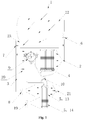
Fig. 1 is a structure schematic diagram of a dryer in an embodiment of the present disclosure; -
Fig. 2 is a structure schematic diagram of a dryer in another embodiment of the present disclosure; -
Fig. 3 is a structure schematic diagram of a dryer in a third embodiment of the present disclosure. - Description of main components: 1-outer drum, 2-air-intake drying air duct, 3-air-exhaust drying air duct, 4-condenser, 5-evaporator, 6- auxiliary heating wire, 7-filter net 8-fan, 9-compressor, 10- throttling device, 11-first three-way control valve, 12-second three-way control valve, 13-first portion, 14-second portion, 15-first evaporator, 16-second evaporator, 17-third three-way control valve, 18-one-way valve, 19-second fan, 20-air-intake end, 21-air-out end, 22-air inlet, 23-air outlet.
- The following is further and specific description of the present disclosure with accompanying embodiment.
- As shown in from
Fig.1 to Fig.3 , a vented dryer having a heat pump system provided in the embodiment of the present disclosure comprises anouter drum 1, an air-intakedrying air duct 2, and an air-exhaustdrying air duct 3. One end of the air-intakedrying air duct 2 is communicated with air inlet of the outer drum, and another end is an air-intake end 20 which is communicated with the atmosphere. One end of the air-exhaustdrying air duct 3 is communicated with theair outlet 23 of the outer drum, and another end is an air-outend 21 which is communicated with the atmosphere. The dryer is further provided with a heat pump system. The heat pump system at least comprising thecondensers 4, athrottling device 10, an evaporator 5 and acompressor 9, which are sequentially connected end to end via a pipeline to from a flow channel for circulating the refrigerant. - In the embodiment of the present disclosure, a condenser is arranged in the air-intake
drying air duct 2, and an evaporator 5 is arranged in the air-exhaustdrying air duct 3. An outlet end of thecompressor 9 is an end for allowing the refrigerant to flow out from the compressor, and this outlet end is connected with thecondenser 4 through the pipeline. An inlet end of thecompressor 9 is the end for allowing the refrigerant to flow into the compressor, and this inlet end is connected with theevaporator 4 through the pipeline. Therefore, under the action of the compressor, the refrigerant medium in the heat pump system circulates in the direction from the outlet end of the compressor to the condenser, the throttling device, the evaporator, and to the inlet end of the compressor. It achieves the purposes of heating the intake air stream which flows through the condenser, and cooling the exhaust air stream which flows through the evaporator, and then achieves the purpose of drying the clothes inside the outer drum. - In the embodiment of the present disclosure, in order to improve the working efficiency of the heat pump system, the
compressor 9 is arranged in the air-intakedrying air duct 2 located upstream from thecondenser 4 to preheat the intake air stream by using the heat radiation during the operation of the compressor. In order to improve the heating speed of the intake air stream and increasing the temperature of the intake air stream flowing into the outer drum, it is preferable that the air-intakedrying air duct 2 is provided with anauxiliary heating wire 6 for electrically heating the air stream passing through. Further and preferably, theauxiliary heating wire 6 is arranged in the air-exhaustdrying air duct 2 located downstream from thecondenser 4, to improve the electric heating efficiency. - In the embodiment of the present disclosure, the air intake drying air duct and/or the air-exhaust drying air duct is provided with a
fan 8 for controlling the air stream direction in the air passage. Preferably, thefan 8 is only arranged in the air-exhaustdrying air duct 3 and located upstream from the evaporator 5. So that the air stream in the air-intakedrying air duct 2 flows from the air-intake end 20 to theair inlet 22, and the air stream in theouter drum 1 flows from theair inlet 22 to theair outlet 23, and the air stream in the air-exhaustdrying air duct 3 flows from theair outlet 23 to the air-outend 21. - In the embodiment of the present disclosure, the air-exhaust
drying air duct 3 is provided with afilter net 7 for filtering the threads in the exhaust air stream. Thefilter net 7 is arranged in the air-exhaustdrying air duct 3 and located upstream from thefan 8 and close to theair outlet 23. - As shown in from Fig.4 to Fig.5, a high efficiency vented dryer having a heat pump system is provided in the embodiment of the present disclosure. The heat pump system of the dryer is provided with a
first evaporator 15 and asecond evaporator 16 arranged in parallel or in series. Thefirst evaporator 15 is arranged in the air-exhaustdrying air duct 3 and thesecond evaporator 16 is arranged in an external atmosphere. - By arranging the evaporators in the drying air duct and the external atmosphere, respectively, the heat pump system can simultaneously or independently absorb heat from the air exhausted by the dryer and the ambient air of the dryer to heat the intake air by using heat in the exhaust air and heat in the environment, so as to improve drying rate of the dryer. Meanwhile, during the process of absorbing heat from the air in the environment, the second evaporator also condenses and collects the water vapor from the air in the environment so as to achieve the purpose of dehumidifying the air in the environment by the dryer.
- Preferably, a
second fan 19 is arranged outside the air-exhaustdrying air duct 3 and is close to the air inlet of thesecond evaporator 16, so as to provide an acting force to the air at the second evaporator. It enables that an airflow flows through the second evaporator. - As shown in
Fig.2 , in the present embodiment, the air-intake end of thefirst evaporator 15 and the air-intake end of thesecond evaporator 16 are respectively communicated with the throttlingdevice 10 of the heat pump system through a first three-way control valve 11. The air-out end of thefirst evaporator 15 and the air-out end of thesecond evaporator 16 are respectively communicated with the air-intake end of thecompressor 9 of the heat pump system through a second three-way control valve 12. So that thefirst evaporator 15 and thesecond evaporator 16 are arranged in parallel and then are connected to the heat pump system. - The three-way control valves are respectively arranged at the air-intake end and the air-out end of the
first evaporator 15 and thesecond evaporator 16 arranged in parallel so as to control the flow direction of the refrigerant medium. So that realizes the purpose that thefirst evaporator 15 and thesecond evaporator 16 can simultaneously or separately absorb heat by using the refrigerant medium flowing through them. - Preferably, in this embodiment, when the dryer is at different working stages, the heat pump is correspondingly in different states to improve the heat absorption saturation of the refrigerant medium and improve the working efficiency of the heat pump system. Specific implementations are as follows:
At the later stage of the drying process of the dryer, the heat pump system is in the first state. The first three-way control valve 11 is only communicated with the air-intake end of thefirst evaporator 15 and the air-out end of the throttling device, and the second three-way control valve 12 is only communicated with the air-out end of thefirst evaporator 15 and the air-intake end of the compressor. It allows the refrigerant medium to only flow through thefirst evaporator 15, without flowing through thesecond evaporator 16. So that the heat pump system only uses thefirst evaporator 15 to absorb heat from the exhaust air. - At the earlier stage of the drying process of the dryer, the heat pump system is in the second state. The first three-
way control valve 11 simultaneously communicates the air-intake end of theevaporator 15 and the air-intake end of thesecond evaporator 16 to the air-out end of thethrottling device 10. The second three-way control valve 12 simultaneously communicates the air-out end of thefirst evaporator 15 and the air-out end of thesecond evaporator 16 to the air-intake end of thecompressor 9. It allows the refrigerant medium to simultaneously flow through thefirst evaporator 15 and thesecond evaporator 16. So that the heat pump system can use thefirst evaporator 15 to absorb heat from the exhaust air and use thesecond evaporator 16 to absorb heat from the air in the environment, simultaneously. - As shown in
Fig.3 , in the present embodiment, the air-out end of thefirst evaporator 15 is respectively communicated with the air-intake end of thesecond evaporator 16 and the air-intake end of thecompressor 9 of the heat pump system through the third three-way control valve 17. The air-out end of thesecond evaporator 16 is communicated with the air-intake end of thecompressor 9 through a one-way valve 18. The flow direction of the refrigerant medium in the one-way valve 18 is from thesecond evaporator 16 to thecompressor 9, so that thefirst evaporator 15 and thesecond evaporator 16 are arranged in series and then are connected to the heat pump system. - The corresponding control valves are respectively arranged at the air-intake end and the air-out end of the
first evaporator 15 and thesecond evaporator 16 arranged in series so as to control the flow direction of the refrigerant medium. So that realizes the purposes that thefirst evaporator 15 and thesecond evaporator 16 simultaneously absorb heat by using the refrigerant medium flowing through them, or the first evaporator 26 individually absorb heat by using the refrigerant medium flowing through it. - Preferably, in this embodiment, when the dryer is at different working stages, the heat pump is correspondingly in different states to improve the heat absorption saturation of the refrigerant medium and improve the working efficiency of the heat pump system. Specific implementations are as follows:
At the later stage of the drying process of the dryer, the heat pump system is in the first state. The third three-way control valve 17 is only communicated with the air-out end of thefirst evaporator 15 and the air-intake end of the compressor. It allows the refrigerant medium to only flow through thefirst evaporator 15, without flowing through thesecond evaporator 16. So that the heat pump system only uses thefirst evaporator 15 to absorb heat from the exhaust air. - At the earlier stage of the drying process of the dryer, the heat pump system is in the second state. The third three-
way control valve 17 communicates the air-out end of thefirst evaporator 15 to the air-intake end of thesecond evaporator 16. It enables the refrigerant medium to flow through thefirst evaporator 15 and thesecond evaporator 16 in turn. So that the heat pump system can simultaneously use thefirst evaporator 15 to absorb heat from the exhaust air and use thesecond evaporator 16 to absorb heat from the air in the environment. - As shown in
Fig.1 , the differences between the present embodiment and the above first and second embodiments are as follows: the heat pump system of the dryer only comprises one evaporator 5. The evaporator 5 crosses the air-exhaustdrying air duct 3, so that a first portion 13 of the evaporator is located in the air-exhaustdrying air duct 3, and the second portion 14 of the evaporator is located in the outside. It enables that the refrigerant medium flowing through the evaporator can flow through the first portion 13 and the second portion 14 in turn. So that the evaporator absorbs heat from the exhaust air using the first portion 13 and absorb heat from the air in the environment using the second portion 14 to realize the purpose of improving the heat absorbing efficiency of the heat pump system. - The implementation solutions of the foregoing embodiments can be further combined or replaced. The embodiments are merely the description of the preferred embodiments of the present invention, but are not intended to limiting the conception and scope of the present invention. Without departing from the scope of the technical solution of the present invention, any changes and modifications made according to the technical essence of the present invention by any persons skilled in the present invention shall all be covered within the scope of the technical solution of the present invention.
Claims (10)
- A high efficiency vented dryer having a heat pump system, comprising: an outer drum, an air-intake drying air duct (2) and an air-exhaust drying air duct (3) for allowing the outer drum (1) communicating with outside respectively, wherein:the dryer is further provided with a heat pump system,the heat pump system comprises a first evaporator (15) and a second evaporator (16) arranged in parallel or in series,the first evaporator (15) is arranged in the air-exhaust drying air duct (3) and the second evaporator (16) is arranged in an external atmosphere so as to absorb heat from the exhaust air and the external air respectively.
- The high efficiency vented dryer having a heat pump system according to claim 1, wherein an air-intake end and an air-out end of the first evaporator (15) and the second evaporator (16) are respectively provided with a control valve for controlling on-off, so that the refrigerant medium in the heat pump system flows through the first evaporator (15) and the second evaporator (16) independently or at the same time.
- The high efficiency vented dryer having a heat pump system according to claim 1, wherein the air-intake end of the first evaporator (15) and the air-intake end of the second evaporator (16) are respectively communicated with an air-out end of a throttling device (10) of the heat pump system through a first three-way control valve (11); and
the air-out end of the first evaporator (15) and the air-out end of the second evaporator (16) are respectively communicated with an air-out end of a compressor (9) of the heat pump system through a second three-way control valve (12). - The high efficiency vented dryer having a heat pump system according to claim 2, wherein the air-out end of the first evaporator (15) is respectively communicated with the air-intake end of the second evaporator (16) and the air-intake end of the compressor (9) of the heat pump system through a third three-way control valve (17);
the air-out end of the second evaporator (16) is communicated with the air-intake end of the compressor (9) of the heat pump system through a one-way valve. - The high efficiency vented dryer having a heat pump system according to claim 3 or 4, wherein at a later stage of a drying process of the dryer, the heat pump system is in a first state in which the refrigerant medium only flows through the first evaporator (15) without flowing through the second evaporator (16);
at an earlier stage of the drying process of the dryer, the heat pump system is in a second state in which the refrigerant medium simultaneously flows through the first evaporator (15) and the second evaporator (16). - The high efficiency vented dryer having a heat pump system according to any one of claims 1 to 4, wherein a condenser (4) of the heat pump system is arranged in the air-intake drying air duct (2),
an air-intake end of the condenser (4) is communicated with the air-out end of the compressor (9) of the heat pump system, and
the air-out end of the condenser (4) is communicated with the air-intake end of the throttling device (10) of the heat pump system. - The high efficiency vented dryer having a heat pump system according to claim 6, wherein the compressor (9) of the heat pump system is arranged in the air-intake drying air duct (2) located upstream from the condenser (4) to preheat the intake air stream.
- The high efficiency vented dryer having a heat pump system according to claim 6, wherein the air-intake drying air duct (2) is provided with an auxiliary heating wire (6),
the auxiliary heating wire (6) is located downstream from the condenser (4), and
the air-exhaust drying air duct (3) is provided with a fan (8) controlling the flow direction of the air stream, the fan is located upstream from the first evaporator (15). - The high efficiency vented dryer having a heat pump system according to claim 6, wherein a second fan (19) is arranged outside the air-exhaust drying air duct (3) and is close to the air inlet of the second evaporator.
- A high efficiency vented dryer having a heat pump system, comprising an outer drum (1), an air-intake drying air duct (2) and an air-exhaust drying air duct for allowing the outer drum (1) communicating with outside (3) respectively, wherein:the dryer is further provided with a heat pump system,the evaporator (5) of the heat pump system crosses the air-exhaust drying air duct (3), so that a first portion (13) of the evaporator (5) is located in the air-exhaust drying air duct (3) while a second portion (14) of the evaporator (5) is located in the outside.
Applications Claiming Priority (2)
| Application Number | Priority Date | Filing Date | Title |
|---|---|---|---|
| CN201510549166.3A CN106480682B (en) | 2015-08-31 | 2015-08-31 | A kind of efficient straight-line heat pump clothes dryer |
| PCT/CN2016/094141 WO2017036281A1 (en) | 2015-08-31 | 2016-08-09 | High efficiency vented clothes dryer having heat pump system |
Publications (3)
| Publication Number | Publication Date |
|---|---|
| EP3346046A1 true EP3346046A1 (en) | 2018-07-11 |
| EP3346046A4 EP3346046A4 (en) | 2018-08-29 |
| EP3346046B1 EP3346046B1 (en) | 2022-01-12 |
Family
ID=58186693
Family Applications (1)
| Application Number | Title | Priority Date | Filing Date |
|---|---|---|---|
| EP16840710.4A Not-in-force EP3346046B1 (en) | 2015-08-31 | 2016-08-09 | High efficiency vented clothes dryer having heat pump system |
Country Status (6)
| Country | Link |
|---|---|
| US (1) | US10689791B2 (en) |
| EP (1) | EP3346046B1 (en) |
| JP (1) | JP2018525165A (en) |
| KR (1) | KR20180068957A (en) |
| CN (1) | CN106480682B (en) |
| WO (1) | WO2017036281A1 (en) |
Families Citing this family (11)
| Publication number | Priority date | Publication date | Assignee | Title |
|---|---|---|---|---|
| CN110151085A (en) * | 2018-02-12 | 2019-08-23 | 青岛海尔洗碗机有限公司 | A heat pump dishwasher and its control method |
| CN108645196B (en) * | 2018-06-04 | 2023-11-07 | 中国科学院理化技术研究所 | Heat pump drying system |
| CN110629481B (en) * | 2018-06-21 | 2023-07-07 | 青岛海尔洗衣机有限公司 | a drying equipment |
| KR102752411B1 (en) | 2019-02-15 | 2025-01-14 | 삼성전자주식회사 | Apparatus and method for treating garment |
| WO2021029556A1 (en) * | 2019-08-14 | 2021-02-18 | 엘지전자 주식회사 | Heat exchanger and method for manufacturing home appliance including heat exchanger |
| US11851807B2 (en) | 2019-11-07 | 2023-12-26 | Whirlpool Corporation | Method of removing heat from a clothes tumbling system on the outside of the cabinet |
| DE102020205594A1 (en) | 2020-05-04 | 2021-11-04 | BSH Hausgeräte GmbH | LAUNDRY MACHINE WITH A HOUSING AND A HEAT PUMP |
| CN113882128B (en) * | 2020-07-02 | 2023-09-29 | 重庆海尔滚筒洗衣机有限公司 | Heat pump clothes dryer and control method thereof |
| CN117626616A (en) * | 2022-08-16 | 2024-03-01 | 广州奕至家居科技有限公司 | Heat pump clothes dryer and two-stage dehumidification system, control method and storage medium |
| US12534848B2 (en) | 2022-10-27 | 2026-01-27 | Haier Us Appliance Solutions, Inc. | Induction heating system for a dryer appliance |
| US12522973B2 (en) | 2023-07-18 | 2026-01-13 | Haier Us Appliance Solutions, Inc. | Air heater for front load washing machine |
Family Cites Families (22)
| Publication number | Priority date | Publication date | Assignee | Title |
|---|---|---|---|---|
| JPH01212599A (en) | 1988-02-22 | 1989-08-25 | Mitsubishi Heavy Ind Ltd | Washer-dryer |
| JP2007143631A (en) | 2005-11-24 | 2007-06-14 | Mitsubishi Electric Corp | Clothes dryer and operation method thereof |
| JP2008086424A (en) | 2006-09-29 | 2008-04-17 | Sanyo Electric Co Ltd | Drier |
| JP2008173330A (en) * | 2007-01-19 | 2008-07-31 | Toshiba Corp | Clothes dryer |
| JP4889545B2 (en) * | 2007-03-30 | 2012-03-07 | 三洋電機株式会社 | Drying apparatus and washing and drying machine equipped with this apparatus |
| KR100925739B1 (en) * | 2007-09-13 | 2009-11-11 | 엘지전자 주식회사 | Ductless dryer |
| CN101896660B (en) * | 2007-12-11 | 2011-12-28 | Bsh博世和西门子家用器具有限公司 | Household appliance comprising a first air conduit and a heat pump |
| DE102008007971A1 (en) | 2008-02-07 | 2009-08-13 | BSH Bosch und Siemens Hausgeräte GmbH | Condensation dryer with heat pump and heater and method for its operation |
| DE102008055087A1 (en) * | 2008-12-22 | 2010-06-24 | BSH Bosch und Siemens Hausgeräte GmbH | Dryer with heat pump and recirculated air and process for its operation |
| WO2011067747A1 (en) * | 2009-12-01 | 2011-06-09 | Budhi Haryanto | Energy-saving and environmentally-friendly multipurpose air conditioning as a generator of dew drinking water, hot water and dryer |
| EP2385169A1 (en) * | 2010-05-03 | 2011-11-09 | Electrolux Home Products Corporation N.V. | A laundry machine with heat pump system and a method for operating the laundry machine |
| CN102002843B (en) * | 2010-11-12 | 2012-07-18 | Tcl空调器(中山)有限公司 | Heat pump type clothes dryer |
| EP2460928B1 (en) * | 2010-12-02 | 2014-02-26 | Electrolux Home Products Corporation N.V. | Method of operating a heat pump dryer and heat pump dryer |
| JP5617602B2 (en) * | 2010-12-21 | 2014-11-05 | パナソニック株式会社 | Dehumidifying and heating device and clothes dryer provided with the same |
| CN102286872B (en) | 2011-07-12 | 2016-11-16 | 青岛海尔滚筒洗衣机有限公司 | A washer-dryer with heat pump drying and dehumidification functions |
| EP2573252B1 (en) | 2011-09-26 | 2014-05-07 | Electrolux Home Products Corporation N.V. | Laundry treatment apparatus with heat pump |
| EP2599912A1 (en) * | 2011-11-30 | 2013-06-05 | Electrolux Home Products Corporation N.V. | Heat pump laundry drying appliance |
| JP2015024116A (en) | 2013-06-18 | 2015-02-05 | 三星電子株式会社Samsung Electronics Co.,Ltd. | Clothes dryer |
| DE102013226398A1 (en) * | 2013-12-18 | 2015-06-18 | BSH Hausgeräte GmbH | Household appliance comprising a functional part mounted on a level base |
| EP2886708B1 (en) * | 2013-12-20 | 2021-02-17 | BSH Hausgeräte GmbH | Washer-dryer |
| KR102204004B1 (en) | 2014-01-16 | 2021-01-18 | 엘지전자 주식회사 | Clothes treating apparatus with heat pump |
| CN104532522A (en) * | 2014-08-22 | 2015-04-22 | 上海伯涵热能科技有限公司 | Air open circle heat pump type drying wardrobe |
-
2015
- 2015-08-31 CN CN201510549166.3A patent/CN106480682B/en active Active
-
2016
- 2016-08-09 EP EP16840710.4A patent/EP3346046B1/en not_active Not-in-force
- 2016-08-09 JP JP2018510953A patent/JP2018525165A/en active Pending
- 2016-08-09 KR KR1020187007660A patent/KR20180068957A/en not_active Ceased
- 2016-08-09 WO PCT/CN2016/094141 patent/WO2017036281A1/en not_active Ceased
- 2016-08-09 US US15/754,115 patent/US10689791B2/en active Active
Also Published As
| Publication number | Publication date |
|---|---|
| US20180245269A1 (en) | 2018-08-30 |
| EP3346046A4 (en) | 2018-08-29 |
| WO2017036281A1 (en) | 2017-03-09 |
| CN106480682A (en) | 2017-03-08 |
| EP3346046B1 (en) | 2022-01-12 |
| CN106480682B (en) | 2019-11-05 |
| US10689791B2 (en) | 2020-06-23 |
| KR20180068957A (en) | 2018-06-22 |
| JP2018525165A (en) | 2018-09-06 |
Similar Documents
| Publication | Publication Date | Title |
|---|---|---|
| EP3346046B1 (en) | High efficiency vented clothes dryer having heat pump system | |
| US10662573B2 (en) | Vented heat pump dryer | |
| CN107724027B (en) | clothes dryer | |
| CN109737625B (en) | Heat pump system, control method and heat pump drying device | |
| KR102009278B1 (en) | A clothes dryer having a expansion valve which is variable according to the driving mode | |
| CN102677439B (en) | A kind of control method removing heat pump clothes dryer evaporimeter frosting and heat pump clothes dryer | |
| CN105222566B (en) | A kind of heat pump drying system with dehumidifier and Waste Heat Reuse | |
| CN204830701U (en) | Dry tunnel room of dehumidification type heat pump | |
| CN205957367U (en) | Dehumidifier system | |
| CN104342898A (en) | Heat pump clothes dryer with auxiliary heating device and control method of heat pump clothes dryer | |
| CN201569247U (en) | Thermal pump dehumidification drying machine | |
| CN106192322A (en) | A kind of condensing laundry dryer and condensing drying method | |
| CN107477909A (en) | A kind of heat pump solution dehumidification type fabric drying machine | |
| CN102908879A (en) | Efficient energy-saving air dehumidifying system | |
| CN103061096B (en) | Heat pump clothes drying system and clothes drying method thereof | |
| CN111074510A (en) | Clothes dryer | |
| CN107899259B (en) | A heat pump drying system that can be used for solution concentration and its operation method | |
| CN204388551U (en) | A kind of heat pump dehumidification dryer | |
| CN103911826A (en) | Heat pump type energy-saving clothes drying device with temperature adjustment function | |
| CN207214512U (en) | Heat pump drying system | |
| CN107034645B (en) | Drying system and drying device | |
| CN205119755U (en) | Heat pump drying system wet and waste heat utilization is taken out in area | |
| CN106400423B (en) | Drying system and drying device | |
| CN206724662U (en) | A frequency conversion air source high temperature drying system | |
| CN105361233A (en) | An intelligent energy-saving and dehumidification integrated flue-cured device that is easy to install |
Legal Events
| Date | Code | Title | Description |
|---|---|---|---|
| STAA | Information on the status of an ep patent application or granted ep patent |
Free format text: STATUS: THE INTERNATIONAL PUBLICATION HAS BEEN MADE |
|
| PUAI | Public reference made under article 153(3) epc to a published international application that has entered the european phase |
Free format text: ORIGINAL CODE: 0009012 |
|
| STAA | Information on the status of an ep patent application or granted ep patent |
Free format text: STATUS: REQUEST FOR EXAMINATION WAS MADE |
|
| 17P | Request for examination filed |
Effective date: 20180328 |
|
| AK | Designated contracting states |
Kind code of ref document: A1 Designated state(s): AL AT BE BG CH CY CZ DE DK EE ES FI FR GB GR HR HU IE IS IT LI LT LU LV MC MK MT NL NO PL PT RO RS SE SI SK SM TR |
|
| AX | Request for extension of the european patent |
Extension state: BA ME |
|
| A4 | Supplementary search report drawn up and despatched |
Effective date: 20180730 |
|
| RIC1 | Information provided on ipc code assigned before grant |
Ipc: D06F 58/20 20060101AFI20180720BHEP |
|
| DAV | Request for validation of the european patent (deleted) | ||
| DAX | Request for extension of the european patent (deleted) | ||
| RIC1 | Information provided on ipc code assigned before grant |
Ipc: D06F 58/20 20060101AFI20210617BHEP Ipc: D06F 58/10 20060101ALN20210617BHEP Ipc: D06F 58/24 20060101ALN20210617BHEP |
|
| GRAP | Despatch of communication of intention to grant a patent |
Free format text: ORIGINAL CODE: EPIDOSNIGR1 |
|
| STAA | Information on the status of an ep patent application or granted ep patent |
Free format text: STATUS: GRANT OF PATENT IS INTENDED |
|
| INTG | Intention to grant announced |
Effective date: 20210723 |
|
| GRAS | Grant fee paid |
Free format text: ORIGINAL CODE: EPIDOSNIGR3 |
|
| GRAA | (expected) grant |
Free format text: ORIGINAL CODE: 0009210 |
|
| STAA | Information on the status of an ep patent application or granted ep patent |
Free format text: STATUS: THE PATENT HAS BEEN GRANTED |
|
| AK | Designated contracting states |
Kind code of ref document: B1 Designated state(s): AL AT BE BG CH CY CZ DE DK EE ES FI FR GB GR HR HU IE IS IT LI LT LU LV MC MK MT NL NO PL PT RO RS SE SI SK SM TR |
|
| REG | Reference to a national code |
Ref country code: GB Ref legal event code: FG4D |
|
| REG | Reference to a national code |
Ref country code: CH Ref legal event code: EP |
|
| REG | Reference to a national code |
Ref country code: DE Ref legal event code: R096 Ref document number: 602016068378 Country of ref document: DE |
|
| REG | Reference to a national code |
Ref country code: IE Ref legal event code: FG4D |
|
| REG | Reference to a national code |
Ref country code: AT Ref legal event code: REF Ref document number: 1462462 Country of ref document: AT Kind code of ref document: T Effective date: 20220215 |
|
| REG | Reference to a national code |
Ref country code: LT Ref legal event code: MG9D |
|
| REG | Reference to a national code |
Ref country code: NL Ref legal event code: MP Effective date: 20220112 |
|
| REG | Reference to a national code |
Ref country code: AT Ref legal event code: MK05 Ref document number: 1462462 Country of ref document: AT Kind code of ref document: T Effective date: 20220112 |
|
| PG25 | Lapsed in a contracting state [announced via postgrant information from national office to epo] |
Ref country code: NL Free format text: LAPSE BECAUSE OF FAILURE TO SUBMIT A TRANSLATION OF THE DESCRIPTION OR TO PAY THE FEE WITHIN THE PRESCRIBED TIME-LIMIT Effective date: 20220112 |
|
| PG25 | Lapsed in a contracting state [announced via postgrant information from national office to epo] |
Ref country code: SE Free format text: LAPSE BECAUSE OF FAILURE TO SUBMIT A TRANSLATION OF THE DESCRIPTION OR TO PAY THE FEE WITHIN THE PRESCRIBED TIME-LIMIT Effective date: 20220112 Ref country code: RS Free format text: LAPSE BECAUSE OF FAILURE TO SUBMIT A TRANSLATION OF THE DESCRIPTION OR TO PAY THE FEE WITHIN THE PRESCRIBED TIME-LIMIT Effective date: 20220112 Ref country code: PT Free format text: LAPSE BECAUSE OF FAILURE TO SUBMIT A TRANSLATION OF THE DESCRIPTION OR TO PAY THE FEE WITHIN THE PRESCRIBED TIME-LIMIT Effective date: 20220512 Ref country code: NO Free format text: LAPSE BECAUSE OF FAILURE TO SUBMIT A TRANSLATION OF THE DESCRIPTION OR TO PAY THE FEE WITHIN THE PRESCRIBED TIME-LIMIT Effective date: 20220412 Ref country code: LT Free format text: LAPSE BECAUSE OF FAILURE TO SUBMIT A TRANSLATION OF THE DESCRIPTION OR TO PAY THE FEE WITHIN THE PRESCRIBED TIME-LIMIT Effective date: 20220112 Ref country code: HR Free format text: LAPSE BECAUSE OF FAILURE TO SUBMIT A TRANSLATION OF THE DESCRIPTION OR TO PAY THE FEE WITHIN THE PRESCRIBED TIME-LIMIT Effective date: 20220112 Ref country code: ES Free format text: LAPSE BECAUSE OF FAILURE TO SUBMIT A TRANSLATION OF THE DESCRIPTION OR TO PAY THE FEE WITHIN THE PRESCRIBED TIME-LIMIT Effective date: 20220112 Ref country code: BG Free format text: LAPSE BECAUSE OF FAILURE TO SUBMIT A TRANSLATION OF THE DESCRIPTION OR TO PAY THE FEE WITHIN THE PRESCRIBED TIME-LIMIT Effective date: 20220412 |
|
| PG25 | Lapsed in a contracting state [announced via postgrant information from national office to epo] |
Ref country code: PL Free format text: LAPSE BECAUSE OF FAILURE TO SUBMIT A TRANSLATION OF THE DESCRIPTION OR TO PAY THE FEE WITHIN THE PRESCRIBED TIME-LIMIT Effective date: 20220112 Ref country code: LV Free format text: LAPSE BECAUSE OF FAILURE TO SUBMIT A TRANSLATION OF THE DESCRIPTION OR TO PAY THE FEE WITHIN THE PRESCRIBED TIME-LIMIT Effective date: 20220112 Ref country code: GR Free format text: LAPSE BECAUSE OF FAILURE TO SUBMIT A TRANSLATION OF THE DESCRIPTION OR TO PAY THE FEE WITHIN THE PRESCRIBED TIME-LIMIT Effective date: 20220413 Ref country code: FI Free format text: LAPSE BECAUSE OF FAILURE TO SUBMIT A TRANSLATION OF THE DESCRIPTION OR TO PAY THE FEE WITHIN THE PRESCRIBED TIME-LIMIT Effective date: 20220112 Ref country code: AT Free format text: LAPSE BECAUSE OF FAILURE TO SUBMIT A TRANSLATION OF THE DESCRIPTION OR TO PAY THE FEE WITHIN THE PRESCRIBED TIME-LIMIT Effective date: 20220112 |
|
| PG25 | Lapsed in a contracting state [announced via postgrant information from national office to epo] |
Ref country code: IS Free format text: LAPSE BECAUSE OF FAILURE TO SUBMIT A TRANSLATION OF THE DESCRIPTION OR TO PAY THE FEE WITHIN THE PRESCRIBED TIME-LIMIT Effective date: 20220512 |
|
| REG | Reference to a national code |
Ref country code: DE Ref legal event code: R097 Ref document number: 602016068378 Country of ref document: DE |
|
| PG25 | Lapsed in a contracting state [announced via postgrant information from national office to epo] |
Ref country code: SM Free format text: LAPSE BECAUSE OF FAILURE TO SUBMIT A TRANSLATION OF THE DESCRIPTION OR TO PAY THE FEE WITHIN THE PRESCRIBED TIME-LIMIT Effective date: 20220112 Ref country code: SK Free format text: LAPSE BECAUSE OF FAILURE TO SUBMIT A TRANSLATION OF THE DESCRIPTION OR TO PAY THE FEE WITHIN THE PRESCRIBED TIME-LIMIT Effective date: 20220112 Ref country code: RO Free format text: LAPSE BECAUSE OF FAILURE TO SUBMIT A TRANSLATION OF THE DESCRIPTION OR TO PAY THE FEE WITHIN THE PRESCRIBED TIME-LIMIT Effective date: 20220112 Ref country code: EE Free format text: LAPSE BECAUSE OF FAILURE TO SUBMIT A TRANSLATION OF THE DESCRIPTION OR TO PAY THE FEE WITHIN THE PRESCRIBED TIME-LIMIT Effective date: 20220112 Ref country code: DK Free format text: LAPSE BECAUSE OF FAILURE TO SUBMIT A TRANSLATION OF THE DESCRIPTION OR TO PAY THE FEE WITHIN THE PRESCRIBED TIME-LIMIT Effective date: 20220112 Ref country code: CZ Free format text: LAPSE BECAUSE OF FAILURE TO SUBMIT A TRANSLATION OF THE DESCRIPTION OR TO PAY THE FEE WITHIN THE PRESCRIBED TIME-LIMIT Effective date: 20220112 |
|
| PGFP | Annual fee paid to national office [announced via postgrant information from national office to epo] |
Ref country code: IT Payment date: 20220831 Year of fee payment: 7 Ref country code: GB Payment date: 20220824 Year of fee payment: 7 Ref country code: DE Payment date: 20220831 Year of fee payment: 7 |
|
| PLBE | No opposition filed within time limit |
Free format text: ORIGINAL CODE: 0009261 |
|
| STAA | Information on the status of an ep patent application or granted ep patent |
Free format text: STATUS: NO OPPOSITION FILED WITHIN TIME LIMIT |
|
| PG25 | Lapsed in a contracting state [announced via postgrant information from national office to epo] |
Ref country code: AL Free format text: LAPSE BECAUSE OF FAILURE TO SUBMIT A TRANSLATION OF THE DESCRIPTION OR TO PAY THE FEE WITHIN THE PRESCRIBED TIME-LIMIT Effective date: 20220112 |
|
| PGFP | Annual fee paid to national office [announced via postgrant information from national office to epo] |
Ref country code: FR Payment date: 20220822 Year of fee payment: 7 |
|
| 26N | No opposition filed |
Effective date: 20221013 |
|
| PG25 | Lapsed in a contracting state [announced via postgrant information from national office to epo] |
Ref country code: SI Free format text: LAPSE BECAUSE OF FAILURE TO SUBMIT A TRANSLATION OF THE DESCRIPTION OR TO PAY THE FEE WITHIN THE PRESCRIBED TIME-LIMIT Effective date: 20220112 |
|
| PG25 | Lapsed in a contracting state [announced via postgrant information from national office to epo] |
Ref country code: MC Free format text: LAPSE BECAUSE OF FAILURE TO SUBMIT A TRANSLATION OF THE DESCRIPTION OR TO PAY THE FEE WITHIN THE PRESCRIBED TIME-LIMIT Effective date: 20220112 |
|
| REG | Reference to a national code |
Ref country code: CH Ref legal event code: PL |
|
| PG25 | Lapsed in a contracting state [announced via postgrant information from national office to epo] |
Ref country code: LU Free format text: LAPSE BECAUSE OF NON-PAYMENT OF DUE FEES Effective date: 20220809 Ref country code: LI Free format text: LAPSE BECAUSE OF NON-PAYMENT OF DUE FEES Effective date: 20220831 Ref country code: CH Free format text: LAPSE BECAUSE OF NON-PAYMENT OF DUE FEES Effective date: 20220831 |
|
| REG | Reference to a national code |
Ref country code: BE Ref legal event code: MM Effective date: 20220831 |
|
| PG25 | Lapsed in a contracting state [announced via postgrant information from national office to epo] |
Ref country code: IE Free format text: LAPSE BECAUSE OF NON-PAYMENT OF DUE FEES Effective date: 20220809 |
|
| PG25 | Lapsed in a contracting state [announced via postgrant information from national office to epo] |
Ref country code: BE Free format text: LAPSE BECAUSE OF NON-PAYMENT OF DUE FEES Effective date: 20220831 |
|
| REG | Reference to a national code |
Ref country code: DE Ref legal event code: R119 Ref document number: 602016068378 Country of ref document: DE |
|
| PG25 | Lapsed in a contracting state [announced via postgrant information from national office to epo] |
Ref country code: HU Free format text: LAPSE BECAUSE OF FAILURE TO SUBMIT A TRANSLATION OF THE DESCRIPTION OR TO PAY THE FEE WITHIN THE PRESCRIBED TIME-LIMIT; INVALID AB INITIO Effective date: 20160809 |
|
| GBPC | Gb: european patent ceased through non-payment of renewal fee |
Effective date: 20230809 |
|
| PG25 | Lapsed in a contracting state [announced via postgrant information from national office to epo] |
Ref country code: CY Free format text: LAPSE BECAUSE OF FAILURE TO SUBMIT A TRANSLATION OF THE DESCRIPTION OR TO PAY THE FEE WITHIN THE PRESCRIBED TIME-LIMIT Effective date: 20220112 |
|
| PG25 | Lapsed in a contracting state [announced via postgrant information from national office to epo] |
Ref country code: MK Free format text: LAPSE BECAUSE OF FAILURE TO SUBMIT A TRANSLATION OF THE DESCRIPTION OR TO PAY THE FEE WITHIN THE PRESCRIBED TIME-LIMIT Effective date: 20220112 |
|
| PG25 | Lapsed in a contracting state [announced via postgrant information from national office to epo] |
Ref country code: GB Free format text: LAPSE BECAUSE OF NON-PAYMENT OF DUE FEES Effective date: 20230809 |
|
| PG25 | Lapsed in a contracting state [announced via postgrant information from national office to epo] |
Ref country code: IT Free format text: LAPSE BECAUSE OF NON-PAYMENT OF DUE FEES Effective date: 20230809 Ref country code: GB Free format text: LAPSE BECAUSE OF NON-PAYMENT OF DUE FEES Effective date: 20230809 Ref country code: FR Free format text: LAPSE BECAUSE OF NON-PAYMENT OF DUE FEES Effective date: 20230831 Ref country code: DE Free format text: LAPSE BECAUSE OF NON-PAYMENT OF DUE FEES Effective date: 20240301 |
|
| PG25 | Lapsed in a contracting state [announced via postgrant information from national office to epo] |
Ref country code: MT Free format text: LAPSE BECAUSE OF FAILURE TO SUBMIT A TRANSLATION OF THE DESCRIPTION OR TO PAY THE FEE WITHIN THE PRESCRIBED TIME-LIMIT Effective date: 20220112 |
|
| PG25 | Lapsed in a contracting state [announced via postgrant information from national office to epo] |
Ref country code: TR Free format text: LAPSE BECAUSE OF FAILURE TO SUBMIT A TRANSLATION OF THE DESCRIPTION OR TO PAY THE FEE WITHIN THE PRESCRIBED TIME-LIMIT Effective date: 20220112 |