EP3345473A1 - Combine harvester - Google Patents
Combine harvester Download PDFInfo
- Publication number
- EP3345473A1 EP3345473A1 EP16841216.1A EP16841216A EP3345473A1 EP 3345473 A1 EP3345473 A1 EP 3345473A1 EP 16841216 A EP16841216 A EP 16841216A EP 3345473 A1 EP3345473 A1 EP 3345473A1
- Authority
- EP
- European Patent Office
- Prior art keywords
- grain
- grain culms
- feeder
- culms
- grain culm
- Prior art date
- Legal status (The legal status is an assumption and is not a legal conclusion. Google has not performed a legal analysis and makes no representation as to the accuracy of the status listed.)
- Granted
Links
Images


Classifications
-
- A—HUMAN NECESSITIES
- A01—AGRICULTURE; FORESTRY; ANIMAL HUSBANDRY; HUNTING; TRAPPING; FISHING
- A01D—HARVESTING; MOWING
- A01D41/00—Combines, i.e. harvesters or mowers combined with threshing devices
- A01D41/12—Details of combines
- A01D41/127—Control or measuring arrangements specially adapted for combines
- A01D41/1271—Control or measuring arrangements specially adapted for combines for measuring crop flow
-
- A—HUMAN NECESSITIES
- A01—AGRICULTURE; FORESTRY; ANIMAL HUSBANDRY; HUNTING; TRAPPING; FISHING
- A01D—HARVESTING; MOWING
- A01D41/00—Combines, i.e. harvesters or mowers combined with threshing devices
- A01D41/12—Details of combines
- A01D41/127—Control or measuring arrangements specially adapted for combines
-
- A—HUMAN NECESSITIES
- A01—AGRICULTURE; FORESTRY; ANIMAL HUSBANDRY; HUNTING; TRAPPING; FISHING
- A01D—HARVESTING; MOWING
- A01D41/00—Combines, i.e. harvesters or mowers combined with threshing devices
- A01D41/12—Details of combines
-
- A—HUMAN NECESSITIES
- A01—AGRICULTURE; FORESTRY; ANIMAL HUSBANDRY; HUNTING; TRAPPING; FISHING
- A01D—HARVESTING; MOWING
- A01D61/00—Elevators or conveyors for binders or combines
-
- A—HUMAN NECESSITIES
- A01—AGRICULTURE; FORESTRY; ANIMAL HUSBANDRY; HUNTING; TRAPPING; FISHING
- A01D—HARVESTING; MOWING
- A01D61/00—Elevators or conveyors for binders or combines
- A01D61/002—Elevators or conveyors for binders or combines transversal conveying devices
- A01D61/004—Elevators or conveyors for binders or combines transversal conveying devices with cylindrical tools
-
- A—HUMAN NECESSITIES
- A01—AGRICULTURE; FORESTRY; ANIMAL HUSBANDRY; HUNTING; TRAPPING; FISHING
- A01D—HARVESTING; MOWING
- A01D61/00—Elevators or conveyors for binders or combines
- A01D61/008—Elevators or conveyors for binders or combines for longitudinal conveying, especially for combines
-
- A—HUMAN NECESSITIES
- A01—AGRICULTURE; FORESTRY; ANIMAL HUSBANDRY; HUNTING; TRAPPING; FISHING
- A01D—HARVESTING; MOWING
- A01D57/00—Delivering mechanisms for harvesters or mowers
- A01D57/12—Rotating rakes
-
- B—PERFORMING OPERATIONS; TRANSPORTING
- B60—VEHICLES IN GENERAL
- B60Y—INDEXING SCHEME RELATING TO ASPECTS CROSS-CUTTING VEHICLE TECHNOLOGY
- B60Y2200/00—Type of vehicle
- B60Y2200/20—Off-Road Vehicles
- B60Y2200/22—Agricultural vehicles
- B60Y2200/222—Harvesters
Definitions
- the present invention is directed to a combine harvester comprising: a reaping device that cuts grain culms that are in an agricultural field; a harvest frame that receives the grain culms cut by the reaping device; a rake-in auger that is disposed within the harvest frame to be rotatable about a rotary axis extending in a right/left direction of a harvester body, the rake-in auger conveying the grain culms inside the harvest frame in the right/left direction of the harvester body to rake in the grain culms toward a rear of the harvester body; and a feeder that is communicatively connected to a rear wall of the harvest frame for conveying the grain culms raked in by the rake-in auger toward the rear of the harvester body.
- the combine harvester described in Patent Literature 1 includes a reaping device (“mowing blade” in Patent Literature 1) that cuts grain culms in an agricultural field, a harvest frame that receives grain culms cut by a reaping device, a rake-in auger (“auger” in Patent Literature 1) that is disposed within the harvest frame so as to be rotatable about a rotary axis extending in the right/left direction of the harvester body, and that conveys the grain culms inside the harvest frame in a right/left direction of the harvester body and rakes in the grain culms toward the rear of the harvester body, and a feeder (“conveyor” in Patent Literature 1) that is communicatively connected to a rear wall of the harvest frame and that conveys the grain culms raked in by the rake-in auger toward the rear of the harvester body.
- a reaping device (“mowing blade” in Patent Literature 1) that cuts grain culms in an agricultural field
- This combine harvester includes a grain culm sensor that detects the presence of grain culms when coming in contact with the grain culms, on the front edge on the inner surface of the ceiling cover of the threshing chamber.
- the grain culm sensor is thereby able to detect whether the combine harvester is in a reaping state in which the grain culms are provided into the threshing chamber or is in a non-reaping state.
- Patent Literature 1 JP H10-215646A
- the grain culms supplied into the threshing chamber are diffused by the rotation of the threshing drum and the like in the threshing chamber. Therefore, the grain culms sometimes fail to contact the grain culm sensor, and there is room for improving the detection precision of the grain culm sensor.
- a combine harvester comprising:
- the grain culm sensor is disposed at the grain culm feed port toward which the mass of grain culms raked up by the rake-in auger are rushed, the grain culms are brought into contact with the grain culm sensor with enhanced possibility and the detection precision of the grain culm sensor is improved.
- the feeder is disposed to be offset to one side relative to a center of the harvest frame in the right/left direction of the harvester body, and the grain culm sensor is disposed at an edge of the grain culm feed port on the other side in the right/left direction of the harvester body.
- the amount of the grain culms that are fed into the grain culm feed port is larger on the other side of the grain culm feed port in the right/left direction of the harvester body than that on the one side. That is, since the grain culm sensor is disposed on the edge of the grain culm feed port into which the larger amount of the grain culms is fed, the reliability with which the grain culms are brought into contact with the grain culm sensor is enhanced, and the detection precision of the grain culm sensor is improved.
- the grain culm sensor is disposed at one side edge and at the other side edge of the grain culm feed port in the right/left direction of the harvester body.
- the grain culms fed from both the right and left sides to the grain culm feed port can be more easily brought into contact with the grain culm sensors positioned at both the right and left edges of the grain culm feed port, and the detection precision of the grain culm sensor is further improved.
- the reaping width and reaping position can be confirmed based on the detection state of the grain culm sensors on the right and left sides. For example, if the grain culm sensors on both the right and left sides detect the presence of the grain culms, it means that the grain culms are reaped along the whole width of the reaping unit, if only the grain culm sensor on the left side detects the presence of the grain culms, it means that the grain culms are reaped only on the left part of the reaping unit, and if only the grain culm sensor on the right side detects the presence of the grain culms, it means that the grain culms are reaped only on the right part of the reaping unit.
- the grain culm sensor includes a claw-shaped detection member that swings when the conveyed grain culms come into contact with the grain culm sensors, to detect the presence of the grain culms, and the detection member swings along a bottom plate of the feeder.
- the detection member swings and detects the presence of the grain culms, thus enabling an improvement of the detection precision of the grain culm sensor to be realized with a simple detection configuration.
- the feeder includes a pair of front and rear rotating members rotatable about the rotary axis extending in the right/left direction of the harvester body, a pair of right and left conveyor chains that are wound around the pair of front and rear rotating members, and a plurality of conveyor guides that extend between the pair of right and left conveyor chains to engage the grain culms
- the feeder is configured to convey the grain culms rearward relative to the harvester body along a lower path of the conveyor chains
- the detection member is disposed at a position between the rotary axis of the front rotating member and a bottom edge of the conveyor guide positioned on the lower path, in a height direction of the grain culm feed port.
- the grain culms conveyed along the lower path tend to lift up from the bottom plate of the feeder. If the position of the detection member in the height direction of the grain culm feed port is too low, there is a risk that when the grain culms lift up, the grain culms will pass above the grain culm sensor and will fail to come in contact with the grain culm sensor. In this regard, according to this characteristic configuration, since the detection member is disposed at a somewhat high position in the height direction of the grain culm feed port, it is easier for the grain culms to come in contact with the grain culm sensor even if the grain culms lift up.
- the grain culm sensor includes a main body that is supported in a cantilever manner by a side plate of the feeder and that supports the detection member, and an intrusion preventing element extends between the side plate and the rear edge of the main body to prevent intrusion of the grain culms into an behind the main body between the main body and the side plate.
- the intrusion of the grain culms into the area at the back of the main body between the main body and the side plate can be prevented by the intrusion preventing element, such a situation can be avoided.
- the direction of the arrow [F] indicates “the front side of the harvester body” and the direction of the arrow [B] indicates “the rear side of the harvester body”; and with reference to Fig. 2 , the direction of the arrow [L] indicates “the left side of the harvester body” and the direction of the arrow R indicates “the right side of the harvester body”.
- Figs. 1 and 2 show a combine harvester (so-called a normal-type combine harvester) including a feeder 13 which will be described later in more detail.
- the combine harvester includes a crawler travel device 1, and a harvester body frame 2 supported by the crawler travel device 1.
- a reaping unit 3 configured to be elevated and lowered, for cutting grain culms in the agricultural field and conveying the cut grain culms rearward relative to the harvester body.
- an operation cabin 4 is provided.
- a threshing device 5 that threshes grain culms and a grain tank 6 that stores the grains are disposed adjacent to each other in the right/left direction of the harvester body.
- the grain tank 6 includes an unloader 7 that discharges the grains from within the grain tank 6.
- the reaping unit 3 includes a pair of right and left dividers 8, a rake-in reel 9, a reaping device 10, a harvest frame 11, a rake-in auger 12, and a feeder 13.
- the divider 8 divides the grain culms in the agricultural field into the grain culms to be reaped and the grain culms not to be reaped.
- the rake-in reel 9 rakes in the grain culms to be reaped out of the grain culms in the agricultural field.
- the reaping device 10 cuts the grain culms raked-in by the rake-in reel 9.
- the harvest frame 11 receives the grain culms cut by the reaping device 10.
- the rake-in auger 12 conveys the grain culms inside the harvest frame 11 in the right/left direction of the harvester body and rakes in the grain culms rearward relative to the harvester body.
- the feeder 13 is communicatively connected to a rear wall of the harvest frame 11, and conveys the grain culms raked in by the rake-in auger 12 rearward relative to the harvester body.
- the rake-in auger 12 is disposed inside the harvest frame 11 to be rotatable about a rotary axis X1 extending in the right/left direction of the harvester body.
- the rake-in auger 12 includes a drum 14, a plurality of rake-in fingers 15, a left screw wing 16 and a right screw wing 17.
- the drum 14 is supported rotatably about the rotary axis X1 on both right and left side walls of the harvest frame 11.
- the rake-in fingers 15 are disposed at portions the drum 14 corresponding to the front of the feeder 13, and configured to protrude from and retreat to the periphery of the drum 14 in association with rotation of the drum 14.
- the left screw wing 16 is disposed at the left part relative to the rake-in fingers 15 on the periphery of the drum 14.
- the right screw wing 17 is disposed at the right part relative to the rake-in fingers 15 on the periphery of the drum 14.
- the length (conveying stroke) of right screw wing 17 is designed to be longer than the length of the left screw wing 16 in the right/left direction of the harvester body.
- the grain culms inside the harvest frame 11 are conveyed by the left screw wing 16 and the right screw wing 17 rightward and leftward, respectively; and then the grain culms are raked in rearward relative to the harvester body by the rake-in fingers 15.
- the feeder 13 is supported by the harvester body to be swingable around a swing axis X2 extending in the right/left direction relative to the harvester body.
- a hydraulic oil cylinder 18 extends between the feeder 13 and the harvester body frame 2.
- the feeder 13 is swung about the swing axis X2 by the hydraulic oil cylinder 18 for lifting and lowering the reaping unit 3.
- the feeder 13 is disposed at a position offset to the left side relative to a center C of the harvest frame 11 in the right/left direction of the harvester body.
- the feeder 13 includes a pair of front and rear rotating members 19, 20, a pair of right and left conveyor chains 21, a plurality of conveyor guides 22, a tension rotating member 23 and a feeder case 24.
- the conveyor chains 21 are wound around the rotating members 19, 20.
- a plurality of conveyor guides 22 extend between the pair of right and left conveyor chains 21 to engage the grain culms.
- the tension rotating member 23 provides the conveyor chains 21 with tension thereof.
- the feeder case 24 accommodates the pair of rotating members 19, 20, the pair of right and left conveyor chains 21, the plurality of conveyor guides 22 and the tension rotating member 23.
- a grain culm feed port 24a is formed at the front edge of the feeder case 24 for introducing the grain culms that are fed from the inside of the harvest frame 11.
- a grain culm sensor 25 is disposed at the grain culm feed port 24a for detecting presence of the grain culms when the grain culms come into contact therewith.
- the feeder case 24 includes a pair of right and left side plates 24A, a top plate 24B and a bottom plate 24C.
- a rear rotating member 20 is disposed at the rear edge of the feeder 13 and is configured to be rotatable about the rotary axis X2 extending in the right/left direction of the harvester body.
- the rear rotating member 20 includes a feeder drive shaft 26 to which power from the engine (not shown) is inputted.
- a front rotating member 19 is disposed at the front edge of the feeder 13 and configured to be rotatable about a rotary axis X3 extending in the right/left direction of the harvester body.
- the front rotating member 19 is configured so that the front/rear position (the front/rear position of the front rotating member 19) can be adjusted by a pair of right and left position adjustment mechanisms 27.
- a pair of scrapers 28 capable of removing substances adhering to the external periphery of the front rotating member 19 are provided.
- the rear rotating member 20 is rotationally driven, and the conveyor chains 21 rotates together with the conveyor guide 22 (in the direction of arrow D as shown in Fig. 4 ).
- the grain culms are thereby conveyed rearward relative to the harvester body along the lower path of the conveyor chains 21, between the lower path and the bottom plate 24C.
- the feeder 13 includes a reverse rotation mechanism (not shown) that reverses the rotational direction of the feeder drive shaft 26.
- the rotational direction of the feeder drive shaft 26 may be reversed by the reverse rotation mechanism to thereby rotate the conveying direction of the feeder 13 reversely forward relative to the harvester body (i.e. in a direction opposite to the arrow D shown in Fig. 4 ).
- the grain culms clogged inside the feeder 13 can be removed.
- a grain culm sensor 25 is disposed at the right and left edges of the grain culm feed port 24a.
- the grain culm sensor 25 is supported on the side plate 24A via a stay 29A so as to be positioned inside the harvest frame 11.
- the grain culm sensor 25 includes a detection member 25A and a main body 25B.
- the detection member 25A is a claw-shaped detection member that detects presence of the grain culms when the grain culms come in contact with the detection member 25A and swing this detection member 25A.
- the main body 25B is supported in a cantilever manner by the side plate 24A via the stay 29A and supports the detection member 25A such that the detection member 25A may swing around a swing axis Z1.
- the tip end thereof extends beyond the conveyor chains 21 to a position toward the center in the right/left direction of the feeder case 24.
- the detection member 25A is configured to swing along the bottom plate 24C around the swing axis Z1, that is, swing substantially in parallel with the bottom plate 24C.
- the state in which the detection member 25A is substantially in parallel with the bottom plate 24C includes a state in which the detection member 25A is slightly tilted relative to the bottom plate 24C, as well as a state in which the detection member 25A is parallel with the bottom plate 24C.
- the detection member 25A is disposed at a position between the rotary axis X3 of the front rotating member 19 and the bottom edge of the conveyor guide 22 positioned at the lower path in the height direction of the grain culm feed port 24a. That is, the detection member 25A is disposed to be offset toward the conveyor guide 22 when this conveyor guide 22 comes on the lower path, within the range S of a space between the rotary axis X3 of the front rotating member 19 and the conveyor guide 22 positioned on the lower path.
- the grain culm sensor 25 is configured as a sensor (volume sensor) that detects the presence of the grain culms according to the amount of the grain culms that is based on the swing angle of the detection member 25A.
- the grain culm sensor 25 is connected to a control device (not shown).
- the control device is configured to determine such that: when at least one of the right and left grain sensor 25 detects the presence of the grain culms, the control device determines that the harvester is in a reaping state; and when neither of the grain culm sensors 25 detects the presence of the grain culms, the control device determines that the harvester is in a non-reaping state.
- the stay 29A includes a vertical portion (longitudinal portion) 29Aa and a lateral portion 29Ab.
- the vertical portion 29Aa extends along the side plate 24A in the front/rear direction of the harvester body.
- the lateral portion 29Ab extends, in the right/left direction of the harvester body, from the front edge of the vertical portion 29Aa toward the right/left center of the feeder case 24.
- the grain culm sensor 25 (the main body 25B) is fixed to the lateral portion 29Ab by a bolt 31 from the front side, with the grain culm sensor 25 being fitted to the back surface of the lateral portion 29Ab.
- an intrusion preventing portion 29B (corresponding to "intrusion preventing element" in the present invention) is formed integrally with the stay 29A.
- the stay 29A and the intrusion preventing portion 29B are integrally fixed to the side plate 24A by the bolt 30 from the lateral inner side.
- the intrusion preventing portion 29B extends between the side plate 24A and the rear edge of the main body 25B.
- the intrusion preventing portion 29B is configured to prevent intrusion of the grain culms into the area at the back of the main body 25B between the main body 25B and the side plate 24A (referred to as "back area” hereinafter).
- back area the area at the back of the main body 25B between the main body 25B and the side plate 24A
- a notched part 29Ba is formed to allow the grain culm sensor 25 (the main body 25B) to extend through the the notched part 29Ba.
- the intrusion preventing portion 29B is overlapped with the front rotating member 19 as seen in the direction of the swing axis Z1 (in the vertical direction relative to the bottom plate 24C).
- the rear end of the intrusion preventing portion 29B is connected to the side plate 24A; and the lower end of the intrusion preventing portion 29B is connected to the bottom plate 24C.
- the grain culms are prevented from intruding into the back area A from the space between the rear end of the intrusion preventing portion 29B and the side plate 24A, or the space between the intrusion preventing portion 29B and the bottom plate 24C.
- the intrusion preventing portion 29B defines a lateral portion, a front oblique portion and a rear oblique portion.
- the lateral portion of the intrusion preventing portion 29B extends along the grain culm feed port 24a in the right/left direction of the harvester body.
- the front oblique portion of the intrusion preventing portion 29B extends diagonally rearward from one edge of the lateral portion adjacent the right/left center of the feeder case 24, toward the right/left center of the feeder case 24 at its tip end extension thereof.
- the rear oblique portion of the intrusion preventing portion 29B extends diagonally rearward from the rear end of the front oblique portion, toward the side plate 24A at its tip end extension thereof.
- the grain culms are received in a wide range in the right/left direction of the harvester body; and on the rear oblique portion of the intrusion preventing portion 29B provided on each of the right and left sides, the grain culms are guided rearward relative to the harvester body in a wide range in the right/left direction of the harvester body.
- the grain culms inside the harvest frame 11 are raked in rearward relative to the harvester body along the bottom plate of the harvest frame 11, and fed toward the grain culm feed port 24a. Then, when the grain culms at the grain culm feed port 24a come in contact with the detection member 25A from the front side, the detection member 25A swings rearward from its initial position P around the swing axis Z1. Thus, the presence of the grain culms is detected by the grain culm sensor 25.
- the intrusion preventing portion 29B prevents the grain culms from intruding into the back area A.
- the grain culm sensor 25 is disposed at the grain culm feed port 24a toward which the mass of grain culms raked up by the rake-in auger 12 are rushed, the grain culms are brought into contact with the grain culm sensor 25 with enhanced possibility and the detection precision of the grain culm sensor 25 is improved.
- the invention has its utility in a wheel type combine harvester, as well as a crawler type combine harvester as described above.
Landscapes
- Life Sciences & Earth Sciences (AREA)
- Environmental Sciences (AREA)
- Harvester Elements (AREA)
- Threshing Machine Elements (AREA)
- Outside Dividers And Delivering Mechanisms For Harvesters (AREA)
- Combines (AREA)
Abstract
Description
- The present invention is directed to a combine harvester comprising: a reaping device that cuts grain culms that are in an agricultural field; a harvest frame that receives the grain culms cut by the reaping device; a rake-in auger that is disposed within the harvest frame to be rotatable about a rotary axis extending in a right/left direction of a harvester body, the rake-in auger conveying the grain culms inside the harvest frame in the right/left direction of the harvester body to rake in the grain culms toward a rear of the harvester body; and a feeder that is communicatively connected to a rear wall of the harvest frame for conveying the grain culms raked in by the rake-in auger toward the rear of the harvester body.
- As a combine harvester such as described above, the combine harvester described in
Patent Literature 1, for example, is already known. The combine harvester described inPatent Literature 1 includes a reaping device ("mowing blade" in Patent Literature 1) that cuts grain culms in an agricultural field, a harvest frame that receives grain culms cut by a reaping device, a rake-in auger ("auger" in Patent Literature 1) that is disposed within the harvest frame so as to be rotatable about a rotary axis extending in the right/left direction of the harvester body, and that conveys the grain culms inside the harvest frame in a right/left direction of the harvester body and rakes in the grain culms toward the rear of the harvester body, and a feeder ("conveyor" in Patent Literature 1) that is communicatively connected to a rear wall of the harvest frame and that conveys the grain culms raked in by the rake-in auger toward the rear of the harvester body. This combine harvester includes a grain culm sensor that detects the presence of grain culms when coming in contact with the grain culms, on the front edge on the inner surface of the ceiling cover of the threshing chamber. The grain culm sensor is thereby able to detect whether the combine harvester is in a reaping state in which the grain culms are provided into the threshing chamber or is in a non-reaping state. - Patent Literature 1:
JP H10-215646A - With regard to the combine harvester described in
Patent Literature 1, the grain culms supplied into the threshing chamber are diffused by the rotation of the threshing drum and the like in the threshing chamber. Therefore, the grain culms sometimes fail to contact the grain culm sensor, and there is room for improving the detection precision of the grain culm sensor. - In view of the above circumstances, there is a need for a combine harvester which may enhance the detection precision of a grain culm sensor by reliably bringing grain culms into contact with the grain culm sensor.
- An aspect of the invention is as under:
A combine harvester comprising: - a reaping device that cuts grain culms that are in an agricultural field;
- a harvest frame that receives the grain culms cut by the reaping device;
- a rake-in auger that is disposed within the harvest frame to be rotatable about a rotary axis extending in a right/left direction of a harvester body, the rake-in auger conveying the grain culms inside the harvest frame in the right/left direction of the harvester body to rake in the grain culms toward a rear of the harvester body; and
- a feeder that is communicatively connected to a rear wall of the harvest frame for conveying the grain culms raked in by the rake-in auger toward the rear of the harvester body, and
- a grain culm sensor that is disposed at a grain culm feed port in the feeder for detecting a presence of the grain culms when the grain culms come into contact with the grain culm sensor.
- According to the above aspect, since the grain culm sensor is disposed at the grain culm feed port toward which the mass of grain culms raked up by the rake-in auger are rushed, the grain culms are brought into contact with the grain culm sensor with enhanced possibility and the detection precision of the grain culm sensor is improved.
- In addition, it is more preferable in the invention, if the feeder is disposed to be offset to one side relative to a center of the harvest frame in the right/left direction of the harvester body, and the grain culm sensor is disposed at an edge of the grain culm feed port on the other side in the right/left direction of the harvester body.
- According to this characteristic configuration, the amount of the grain culms that are fed into the grain culm feed port is larger on the other side of the grain culm feed port in the right/left direction of the harvester body than that on the one side. That is, since the grain culm sensor is disposed on the edge of the grain culm feed port into which the larger amount of the grain culms is fed, the reliability with which the grain culms are brought into contact with the grain culm sensor is enhanced, and the detection precision of the grain culm sensor is improved.
- In addition, it is more preferable in the invention, if the grain culm sensor is disposed at one side edge and at the other side edge of the grain culm feed port in the right/left direction of the harvester body.
- According to this characteristic configuration, the grain culms fed from both the right and left sides to the grain culm feed port can be more easily brought into contact with the grain culm sensors positioned at both the right and left edges of the grain culm feed port, and the detection precision of the grain culm sensor is further improved.
- Moreover, when the harvester body is caused to travel automatically, the reaping width and reaping position can be confirmed based on the detection state of the grain culm sensors on the right and left sides. For example, if the grain culm sensors on both the right and left sides detect the presence of the grain culms, it means that the grain culms are reaped along the whole width of the reaping unit, if only the grain culm sensor on the left side detects the presence of the grain culms, it means that the grain culms are reaped only on the left part of the reaping unit, and if only the grain culm sensor on the right side detects the presence of the grain culms, it means that the grain culms are reaped only on the right part of the reaping unit.
- In addition, it is more preferable in the invention, if the grain culm sensor includes a claw-shaped detection member that swings when the conveyed grain culms come into contact with the grain culm sensors, to detect the presence of the grain culms, and the detection member swings along a bottom plate of the feeder.
- According to this characteristic configuration, when the grain culms on the bottom plate come in contact with the detection member, the detection member swings and detects the presence of the grain culms, thus enabling an improvement of the detection precision of the grain culm sensor to be realized with a simple detection configuration.
- In addition, it is more preferable in the invention, if the feeder includes a pair of front and rear rotating members rotatable about the rotary axis extending in the right/left direction of the harvester body, a pair of right and left conveyor chains that are wound around the pair of front and rear rotating members, and a plurality of conveyor guides that extend between the pair of right and left conveyor chains to engage the grain culms,
the feeder is configured to convey the grain culms rearward relative to the harvester body along a lower path of the conveyor chains, and
the detection member is disposed at a position between the rotary axis of the front rotating member and a bottom edge of the conveyor guide positioned on the lower path, in a height direction of the grain culm feed port. - The grain culms conveyed along the lower path tend to lift up from the bottom plate of the feeder. If the position of the detection member in the height direction of the grain culm feed port is too low, there is a risk that when the grain culms lift up, the grain culms will pass above the grain culm sensor and will fail to come in contact with the grain culm sensor. In this regard, according to this characteristic configuration, since the detection member is disposed at a somewhat high position in the height direction of the grain culm feed port, it is easier for the grain culms to come in contact with the grain culm sensor even if the grain culms lift up.
- In addition, it is more preferable in the invention, if the grain culm sensor includes a main body that is supported in a cantilever manner by a side plate of the feeder and that supports the detection member, and
an intrusion preventing element extends between the side plate and the rear edge of the main body to prevent intrusion of the grain culms into an behind the main body between the main body and the side plate. - If the grain culms pass under the main body and intrude into the area at the back of the main body between the main body and the side plate, there is a risk that the grain culms will become clogged in the area and the operation of the detection member will be hindered. In this regard, according to the invention, since the intrusion of the grain culms into the area at the back of the main body between the main body and the side plate can be prevented by the intrusion preventing element, such a situation can be avoided.
-
-
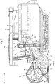
Fig. 1 is a left side view showing a combine harvester; -
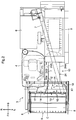
Fig. 2 is a plan view showing the combine harvester; -
Fig. 3 is a plan view in section showing showing the vicinity of the front edge portion of a feeder; -
Fig. 4 is a left side view in section showing the vicinity of the front edge portion of the feeder; -
Fig. 5 is a front view showing the vicinity of the front edge portion of the feeder; -
Fig. 6 is a plan view in section showing arrangement of grain culm sensors; -
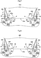
Fig. 7 is a plan view in section showing grain culm sensors according to a first other embodiment of the invention; and -
Fig. 8 is a plan view in section showing grain culm sensors according to a second other embodiment of the invention. - Embodiments of the invention will be described with reference to the figures. In the description to follow, with reference to
Figs. 1 and2 , the direction of the arrow [F] indicates "the front side of the harvester body" and the direction of the arrow [B] indicates "the rear side of the harvester body"; and with reference toFig. 2 , the direction of the arrow [L] indicates "the left side of the harvester body" and the direction of the arrow R indicates "the right side of the harvester body". -
Figs. 1 and2 show a combine harvester (so-called a normal-type combine harvester) including afeeder 13 which will be described later in more detail. The combine harvester includes acrawler travel device 1, and aharvester body frame 2 supported by thecrawler travel device 1. In the front portion of theharvester body frame 2, there is disposed a reapingunit 3 configured to be elevated and lowered, for cutting grain culms in the agricultural field and conveying the cut grain culms rearward relative to the harvester body. Rearward of the reapingunit 3, anoperation cabin 4 is provided. Rearward of theoperation cabin 4, a threshingdevice 5 that threshes grain culms and agrain tank 6 that stores the grains are disposed adjacent to each other in the right/left direction of the harvester body. Thegrain tank 6 includes anunloader 7 that discharges the grains from within thegrain tank 6. - The reaping
unit 3 includes a pair of right andleft dividers 8, a rake-inreel 9, areaping device 10, aharvest frame 11, a rake-inauger 12, and afeeder 13. Thedivider 8 divides the grain culms in the agricultural field into the grain culms to be reaped and the grain culms not to be reaped. The rake-inreel 9 rakes in the grain culms to be reaped out of the grain culms in the agricultural field. The reapingdevice 10 cuts the grain culms raked-in by the rake-inreel 9. Theharvest frame 11 receives the grain culms cut by the reapingdevice 10. The rake-inauger 12 conveys the grain culms inside theharvest frame 11 in the right/left direction of the harvester body and rakes in the grain culms rearward relative to the harvester body. Thefeeder 13 is communicatively connected to a rear wall of theharvest frame 11, and conveys the grain culms raked in by the rake-inauger 12 rearward relative to the harvester body. - The rake-in
auger 12 is disposed inside theharvest frame 11 to be rotatable about a rotary axis X1 extending in the right/left direction of the harvester body. The rake-inauger 12 includes adrum 14, a plurality of rake-infingers 15, aleft screw wing 16 and aright screw wing 17. - The
drum 14 is supported rotatably about the rotary axis X1 on both right and left side walls of theharvest frame 11. The rake-infingers 15 are disposed at portions thedrum 14 corresponding to the front of thefeeder 13, and configured to protrude from and retreat to the periphery of thedrum 14 in association with rotation of thedrum 14. Theleft screw wing 16 is disposed at the left part relative to the rake-infingers 15 on the periphery of thedrum 14. Theright screw wing 17 is disposed at the right part relative to the rake-infingers 15 on the periphery of thedrum 14. The length (conveying stroke) ofright screw wing 17 is designed to be longer than the length of theleft screw wing 16 in the right/left direction of the harvester body. - In operation of the rake-in
auger 12, the grain culms inside theharvest frame 11 are conveyed by theleft screw wing 16 and theright screw wing 17 rightward and leftward, respectively; and then the grain culms are raked in rearward relative to the harvester body by the rake-infingers 15. - The
feeder 13 is supported by the harvester body to be swingable around a swing axis X2 extending in the right/left direction relative to the harvester body. Ahydraulic oil cylinder 18 extends between thefeeder 13 and theharvester body frame 2. Thefeeder 13 is swung about the swing axis X2 by thehydraulic oil cylinder 18 for lifting and lowering the reapingunit 3. Also, thefeeder 13 is disposed at a position offset to the left side relative to a center C of theharvest frame 11 in the right/left direction of the harvester body. - The
feeder 13 includes a pair of front and rearrotating members conveyor chains 21, a plurality of conveyor guides 22, atension rotating member 23 and afeeder case 24. Theconveyor chains 21 are wound around the rotatingmembers conveyor chains 21 to engage the grain culms. Thetension rotating member 23 provides theconveyor chains 21 with tension thereof. Thefeeder case 24 accommodates the pair of rotatingmembers conveyor chains 21, the plurality of conveyor guides 22 and thetension rotating member 23. - A grain
culm feed port 24a is formed at the front edge of thefeeder case 24 for introducing the grain culms that are fed from the inside of theharvest frame 11. Agrain culm sensor 25 is disposed at the grainculm feed port 24a for detecting presence of the grain culms when the grain culms come into contact therewith. Thefeeder case 24 includes a pair of right and leftside plates 24A, atop plate 24B and abottom plate 24C. - A rear rotating
member 20 is disposed at the rear edge of thefeeder 13 and is configured to be rotatable about the rotary axis X2 extending in the right/left direction of the harvester body. The rear rotatingmember 20 includes afeeder drive shaft 26 to which power from the engine (not shown) is inputted. - As shown in
Figs. 3 to 5 , a front rotatingmember 19 is disposed at the front edge of thefeeder 13 and configured to be rotatable about a rotary axis X3 extending in the right/left direction of the harvester body. The front rotatingmember 19 is configured so that the front/rear position (the front/rear position of the front rotating member 19) can be adjusted by a pair of right and leftposition adjustment mechanisms 27. A pair ofscrapers 28 capable of removing substances adhering to the external periphery of the front rotatingmember 19 are provided. - In the
feeder 13, when power from the engine is inputted to thefeeder drive shaft 26, the rear rotatingmember 20 is rotationally driven, and theconveyor chains 21 rotates together with the conveyor guide 22 (in the direction of arrow D as shown inFig. 4 ). The grain culms are thereby conveyed rearward relative to the harvester body along the lower path of theconveyor chains 21, between the lower path and thebottom plate 24C. - In addition, the
feeder 13 includes a reverse rotation mechanism (not shown) that reverses the rotational direction of thefeeder drive shaft 26. When the grain culms are clogged inside thefeeder 13, the rotational direction of thefeeder drive shaft 26 may be reversed by the reverse rotation mechanism to thereby rotate the conveying direction of thefeeder 13 reversely forward relative to the harvester body (i.e. in a direction opposite to the arrow D shown inFig. 4 ). As the grain culms thereby conveyed forward relative to the harvester body, the grain culms clogged inside thefeeder 13 can be removed. - As shown in
Figs. 3 to 6 , agrain culm sensor 25 is disposed at the right and left edges of the grainculm feed port 24a. Thegrain culm sensor 25 is supported on theside plate 24A via astay 29A so as to be positioned inside theharvest frame 11. Thegrain culm sensor 25 includes adetection member 25A and amain body 25B. Thedetection member 25A is a claw-shaped detection member that detects presence of the grain culms when the grain culms come in contact with thedetection member 25A and swing thisdetection member 25A. Themain body 25B is supported in a cantilever manner by theside plate 24A via thestay 29A and supports thedetection member 25A such that thedetection member 25A may swing around a swing axis Z1. - When the
detection member 25A is in its initial position P (i.e. when the grain culms are not in contact therewith), the tip end thereof (the tip end of thedetection member 25A) extends beyond theconveyor chains 21 to a position toward the center in the right/left direction of thefeeder case 24. Thedetection member 25A is configured to swing along thebottom plate 24C around the swing axis Z1, that is, swing substantially in parallel with thebottom plate 24C. Incidentally, the state in which thedetection member 25A is substantially in parallel with thebottom plate 24C includes a state in which thedetection member 25A is slightly tilted relative to thebottom plate 24C, as well as a state in which thedetection member 25A is parallel with thebottom plate 24C. - The
detection member 25A is disposed at a position between the rotary axis X3 of the front rotatingmember 19 and the bottom edge of theconveyor guide 22 positioned at the lower path in the height direction of the grainculm feed port 24a. That is, thedetection member 25A is disposed to be offset toward theconveyor guide 22 when thisconveyor guide 22 comes on the lower path, within the range S of a space between the rotary axis X3 of the front rotatingmember 19 and theconveyor guide 22 positioned on the lower path. - The
grain culm sensor 25 is configured as a sensor (volume sensor) that detects the presence of the grain culms according to the amount of the grain culms that is based on the swing angle of thedetection member 25A. Thegrain culm sensor 25 is connected to a control device (not shown). The control device is configured to determine such that: when at least one of the right and leftgrain sensor 25 detects the presence of the grain culms, the control device determines that the harvester is in a reaping state; and when neither of thegrain culm sensors 25 detects the presence of the grain culms, the control device determines that the harvester is in a non-reaping state. - The
stay 29A includes a vertical portion (longitudinal portion) 29Aa and a lateral portion 29Ab. The vertical portion 29Aa extends along theside plate 24A in the front/rear direction of the harvester body. The lateral portion 29Ab extends, in the right/left direction of the harvester body, from the front edge of the vertical portion 29Aa toward the right/left center of thefeeder case 24. The grain culm sensor 25 (themain body 25B) is fixed to the lateral portion 29Ab by abolt 31 from the front side, with thegrain culm sensor 25 being fitted to the back surface of the lateral portion 29Ab. In addition, anintrusion preventing portion 29B (corresponding to "intrusion preventing element" in the present invention) is formed integrally with thestay 29A. Thestay 29A and theintrusion preventing portion 29B are integrally fixed to theside plate 24A by thebolt 30 from the lateral inner side. - The
intrusion preventing portion 29B extends between theside plate 24A and the rear edge of themain body 25B. Theintrusion preventing portion 29B is configured to prevent intrusion of the grain culms into the area at the back of themain body 25B between themain body 25B and theside plate 24A (referred to as "back area" hereinafter). At theintrusion preventing portion 29B, a notched part 29Ba is formed to allow the grain culm sensor 25 (themain body 25B) to extend through the the notched part 29Ba. Theintrusion preventing portion 29B is overlapped with the front rotatingmember 19 as seen in the direction of the swing axis Z1 (in the vertical direction relative to thebottom plate 24C). The rear end of theintrusion preventing portion 29B is connected to theside plate 24A; and the lower end of theintrusion preventing portion 29B is connected to thebottom plate 24C. Thus, the grain culms are prevented from intruding into the back area A from the space between the rear end of theintrusion preventing portion 29B and theside plate 24A, or the space between theintrusion preventing portion 29B and thebottom plate 24C. - The
intrusion preventing portion 29B defines a lateral portion, a front oblique portion and a rear oblique portion. The lateral portion of theintrusion preventing portion 29B extends along the grainculm feed port 24a in the right/left direction of the harvester body. The front oblique portion of theintrusion preventing portion 29B extends diagonally rearward from one edge of the lateral portion adjacent the right/left center of thefeeder case 24, toward the right/left center of thefeeder case 24 at its tip end extension thereof. The rear oblique portion of theintrusion preventing portion 29B extends diagonally rearward from the rear end of the front oblique portion, toward theside plate 24A at its tip end extension thereof. With such configuration, on the front oblique portion of theintrusion preventing portion 29B provided on each of the right and left sides, the grain culms are received in a wide range in the right/left direction of the harvester body; and on the rear oblique portion of theintrusion preventing portion 29B provided on each of the right and left sides, the grain culms are guided rearward relative to the harvester body in a wide range in the right/left direction of the harvester body. - By the rake-in
auger 12, the grain culms inside theharvest frame 11 are raked in rearward relative to the harvester body along the bottom plate of theharvest frame 11, and fed toward the grainculm feed port 24a. Then, when the grain culms at the grainculm feed port 24a come in contact with thedetection member 25A from the front side, thedetection member 25A swings rearward from its initial position P around the swing axis Z1. Thus, the presence of the grain culms is detected by thegrain culm sensor 25. In addition, even if the grain culms is to go through the space under thegrain culm sensor 25 to enter the back area A, theintrusion preventing portion 29B prevents the grain culms from intruding into the back area A. Thus, according to the instant embodiment, since thegrain culm sensor 25 is disposed at the grainculm feed port 24a toward which the mass of grain culms raked up by the rake-inauger 12 are rushed, the grain culms are brought into contact with thegrain culm sensor 25 with enhanced possibility and the detection precision of thegrain culm sensor 25 is improved. -
- (1) As shown in
Fig. 7 , there may be provided a restrictingmember 32 that is configured to restrict forward swinging of thedetection member 25A from the initial position P around the swing axis Z1. Such a restrictingmember 32 may be configured by a round rod member, for example.
According to the structure, when the rotational direction of thefeeder 13 is reversed by the reverse rotation mechanism toward the front of the harvester body, even if the grain culms conveyed toward to the front of the harvester body come in contact with thedetection member 25A from the rear side, the swinging of thedetection member 25A forward from the initial position P around the swing axis Z1 is restricted by the restrictingmember 32 by the contact of the restrictingmember 32 with thedetection member 25A. Thus, even if the grain culms come into contact with thedetection member 25A from the rear side, thedetection member 25A is not overloaded, thus preventing thedetection member 25A from being damaged.
Alternatively, as shown inFig. 8 , thegrain culm sensor 25 may be configured to swing forward from the initial position P around the swing axis Z1.
According to this configuration, when the conveying direction of thefeeder 13 is reversed by the reverse rotation mechanism toward the front of the harvester body, even if the grain culms conveyed toward the front of the harvester body come in contact with thedetection member 25A from the rear side, the swinging of thedetection member 25A forward from the initial position P around the swing axis Z1 is allowed, thus preventing thedetection member 25A from being overloaded, and thedetection member 25A from being damaged. - (2) In the foregoing embodiment, the
grain culm sensor 25 is constituted by a volume sensor. Alternatively, thegrain culm sensor 25 may be constituted by an ON/OFF sensor as well, that is configured to detect presence of the grain culms based on detection whether thedetection member 25A swings to a certain angle or not. In addition, thegrain culm sensor 25 is constituted by a claw-type sensor, but may be any type of contact sensor, and not necessarily a claw-type sensor. - (3) In the foregoing embodiment, the
grain culm sensor 25 is disposed at the right and left edges of the grainculm feed port 24a, but may also be disposed only on the right edge of the grainculm feed port 24a, or only on the left edge of the grainculm feed port 24a. - (4) In the foregoing embodiment, the
detection member 25A is disposed at a position between the rotary axis X3 of the front rotatingmember 19 and the lower edge of theconveyor guide 22 positioned on the lower path in the height direction of the grainculm feed port 24a, but may also be disposed at a position lower than the lower edge of theconveyor guide 22 that is positioned at the lower path. - (5) In the foregoing embodiment, the
feeder 13 is disposed at a position offset to the left side relative to/from the center C of theharvest frame 11 in the right/left direction of the harvester body, but the invention is not limited thereto. For example, thefeeder 13 may be disposed at a position offset to the right side relative to the center C of theharvest frame 11 in the right/left direction of the harvester body, or the feeder may be disposed at the center of theharvest frame 11. - (6) In the foregoing embodiment, the
intrusion preventing portion 29B is formed integrally with thestay 29A, but theintrusion preventing portion 29B may also be configured separately from thestay 29A. Also, the shape of theintrusion preventing element 29B is not limited to the shape that is described in the foregoing embodiment. Further, theintrusion preventing element 29B may be omitted. - (7) In the foregoing embodiment, the
stay 29A and theintrusion preventing portion 29B are fixed integrally by thebolt 30, but may be fixed by welding, or thestay 29A and theintrusion preventing portion 29B may be fixed individually. - (8) When the harvester body is to be travelled automatically, the reaping width and the reaping position can be confirmed based on the detection state of the
grain culm sensors 25 on the right and left sides. For example, if thegrain culm sensors 25 on both the right and left sides detect the presence of the grain culms, it means that the grain culms are reaped along the whole width of the reapingunit 3; whereas, if thegrain culm sensor 25 on only the left side detects the presence of the grain culms, it means that the grain culms are reaped on only the left part of the reapingunit 3; and if thegrain culm sensor 25 on only the right side detects the presence of the grain culms, it means that the grain culms are reaped on only the right part of the reapingunit 3. - The invention has its utility in a wheel type combine harvester, as well as a crawler type combine harvester as described above.
-
- 10: Reaping device
- 11: Harvest frame
- 12: Rake-in auger
- 13: Feeder
- 19: Front rotating member
- 20: Rear rotating member
- 21: Conveyor chain
- 22: Conveyor guide
- 24A: Side plate
- 24C: Bottom plate
- 24a: Grain culm feed port
- 25: Grain culm sensor
- 25A: Detection member
- 25B: Main body
- 29C: Intrusion preventing portion (Intrusion preventing element)
- A: Back area (Area at the back of the main body between the main body and the side plate)
- C: Center of the harvest frame
- X1: Rotary axis (Rotary axis of the rake-in auger)
- X2: Rotary axis (Rotary axis of the rear rotating member)
- X3: Rotary axis (Rotary axis of the front rotating member)
Claims (6)
- A combine harvester comprising:a reaping device that cuts grain culms that are in an agricultural field;a harvest frame that receives the grain culms cut by the reaping device;a rake-in auger that is disposed within the harvest frame to be rotatable about a rotary axis extending in a right/left direction of a harvester body, the rake-in auger conveying the grain culms inside the harvest frame in the right/left direction of the harvester body to rake in the grain culms toward a rear of the harvester body; anda feeder that is communicatively connected to a rear wall of the harvest frame for conveying the grain culms raked in by the rake-in auger toward the rear of the harvester body, anda grain culm sensor that is disposed at a grain culm feed port in the feeder for detecting a presence of the grain culms when the grain culms come into contact with the grain culm sensor.
- The combine harvester according to claim 1, wherein
the feeder is disposed to be offset to one side relative to a center of the harvest frame in the right/left direction of the harvester body, and
the grain culm sensor is disposed at an edge of the grain culm feed port on the other side in the right/left direction of the harvester body. - The combine harvester according to claim 1 or 2, wherein the grain culm sensor is disposed at one side edge and at the other side edge of the grain culm feed port in the right/left direction of the harvester body.
- The combine harvester according to any one of claims 1 to 3, wherein
the grain culm sensor includes a claw-shaped detection member that swings when the conveyed grain culms come into contact with the grain culm sensor, to detect the presence of the grain culms, and
the detection member swings along a bottom plate of the feeder. - The combine harvester according to claim 4, wherein
the feeder includes a pair of front and rear rotating members rotatable about the rotary axis extending in the right/left direction of the harvester body, a pair of right and left conveyor chains that are wound around the pair of front and rear rotating members, and a plurality of conveyor guides that extend between the pair of right and left conveyor chains to engage the grain culms,
the feeder is configured to convey the grain culms rearward relative to the harvester body along a lower path of the conveyor chains, and
the detection member is disposed at a position between the rotary axis of the front rotating member and a bottom edge of the conveyor guide positioned on the lower path, in a height direction of the grain culm feed port. - The combine harvester according to claim 4 or 5, wherein
the grain culm sensor includes a main body that is supported in a cantilever manner by a side plate of the feeder and that supports the detection member, and
an intrusion preventing element extends between the side plate and the rear edge of the main body to prevent intrusion of the grain culms into an behind the main body between the main body and the side plate.
Applications Claiming Priority (2)
| Application Number | Priority Date | Filing Date | Title |
|---|---|---|---|
| JP2015173106A JP6675843B2 (en) | 2015-09-02 | 2015-09-02 | Combine |
| PCT/JP2016/066816 WO2017038184A1 (en) | 2015-09-02 | 2016-06-07 | Combine harvester |
Publications (3)
| Publication Number | Publication Date |
|---|---|
| EP3345473A1 true EP3345473A1 (en) | 2018-07-11 |
| EP3345473A4 EP3345473A4 (en) | 2019-05-22 |
| EP3345473B1 EP3345473B1 (en) | 2020-12-02 |
Family
ID=58188873
Family Applications (1)
| Application Number | Title | Priority Date | Filing Date |
|---|---|---|---|
| EP16841216.1A Active EP3345473B1 (en) | 2015-09-02 | 2016-06-07 | Combine harvester |
Country Status (6)
| Country | Link |
|---|---|
| US (1) | US10512216B2 (en) |
| EP (1) | EP3345473B1 (en) |
| JP (1) | JP6675843B2 (en) |
| KR (1) | KR102589680B1 (en) |
| CN (1) | CN107613752B (en) |
| WO (1) | WO2017038184A1 (en) |
Families Citing this family (13)
| Publication number | Priority date | Publication date | Assignee | Title |
|---|---|---|---|---|
| JP7072379B2 (en) * | 2017-06-26 | 2022-05-20 | 株式会社クボタ | Harvester |
| US11589508B2 (en) | 2017-06-26 | 2023-02-28 | Kubota Corporation | Field map generating system |
| JP6768602B2 (en) * | 2017-06-26 | 2020-10-14 | 株式会社クボタ | Field map generation system |
| JP7034609B2 (en) * | 2017-06-26 | 2022-03-14 | 株式会社クボタ | Harvester |
| WO2019003728A1 (en) | 2017-06-26 | 2019-01-03 | 株式会社クボタ | Harvesting machine |
| JP6768601B2 (en) * | 2017-06-26 | 2020-10-14 | 株式会社クボタ | Field map generation system |
| EP3646705B1 (en) | 2017-06-26 | 2023-10-18 | Kubota Corporation | Harvesting machine |
| JP2019170315A (en) * | 2018-03-29 | 2019-10-10 | 株式会社クボタ | Combine |
| USD888107S1 (en) * | 2018-06-22 | 2020-06-23 | Kverneland Group Kerteminde As | Suspension unit for agricultural mower unit |
| US11160208B2 (en) * | 2019-04-29 | 2021-11-02 | Deere & Company | Method and apparatus for sensing crop material in a harvester |
| CN113766827B (en) * | 2019-06-26 | 2023-05-09 | 株式会社久保田 | combine harvester |
| US20230021541A1 (en) * | 2019-12-26 | 2023-01-26 | Kubota Corporation | Combine, Grain Separation Method, Grain Separation System, Grain Separation Program, Recording Medium on Which Grain Separation Program Is Recorded, Grain Inspection Method, Grain Inspection System, Grain Inspection Program, and Recording Medium on Which Grain Inspection Program Is Recorded |
| US12582037B2 (en) * | 2022-10-31 | 2026-03-24 | Deere & Company | Draper drum floor vanes |
Family Cites Families (36)
| Publication number | Priority date | Publication date | Assignee | Title |
|---|---|---|---|---|
| DE2705491C2 (en) * | 1977-02-10 | 1983-03-31 | Gebr.Claas Maschinenfabrik GmbH, 4834 Harsewinkel | Sensing device for lateral guidance of a harvesting machine |
| JPS56104324U (en) * | 1980-01-16 | 1981-08-14 | ||
| JPS63159736U (en) * | 1987-04-07 | 1988-10-19 | ||
| JP2516363B2 (en) * | 1987-04-10 | 1996-07-24 | ヤンマー農機株式会社 | Vehicle speed control device for work vehicle |
| JPH0538982Y2 (en) * | 1987-10-09 | 1993-10-01 | ||
| JPH0253415A (en) * | 1988-08-17 | 1990-02-22 | Iseki & Co Ltd | Combine harvester reaping device |
| DK0505538T3 (en) * | 1990-10-12 | 1995-09-25 | British Tech Group | Crop sensing apparatus |
| JPH08308365A (en) * | 1995-05-15 | 1996-11-26 | Kubota Corp | Combine |
| JP3310542B2 (en) * | 1996-06-04 | 2002-08-05 | 株式会社クボタ | Combine handling depth control device |
| JPH10215646A (en) | 1997-02-10 | 1998-08-18 | Kubota Corp | Combine rolling control device |
| US6121782A (en) | 1997-04-09 | 2000-09-19 | Case Corporation | Method for measuring yield and moisture |
| JPH11220929A (en) * | 1998-02-09 | 1999-08-17 | Iseki & Co Ltd | Combine |
| JP2000060274A (en) * | 1998-08-26 | 2000-02-29 | Yanmar Agricult Equip Co Ltd | Vehicle speed control device for agricultural work machine |
| US6591145B1 (en) * | 2000-09-21 | 2003-07-08 | Bechtel Bwxt Idaho, Llc | Systems and methods for autonomously controlling agricultural machinery |
| JP2002360036A (en) * | 2001-06-07 | 2002-12-17 | Iseki & Co Ltd | Combine harvester |
| DE10130665A1 (en) * | 2001-06-28 | 2003-01-23 | Deere & Co | Device for measuring the amount of plants in a field |
| US6553300B2 (en) * | 2001-07-16 | 2003-04-22 | Deere & Company | Harvester with intelligent hybrid control system |
| DE10147733A1 (en) * | 2001-09-27 | 2003-04-10 | Claas Selbstfahr Erntemasch | Method and device for determining a harvester setting |
| US6834484B2 (en) * | 2001-12-18 | 2004-12-28 | Deere & Company | Automatic control initiation for a harvester |
| US6726559B2 (en) * | 2002-05-14 | 2004-04-27 | Deere & Company | Harvester with control system considering operator feedback |
| DE10327758A1 (en) * | 2003-06-18 | 2005-01-05 | Claas Selbstfahrende Erntemaschinen Gmbh | Method for controlling a threshing unit of a combine harvester |
| JP2006014666A (en) * | 2004-07-01 | 2006-01-19 | Yanmar Co Ltd | Reaping device of combine harvester |
| US7367880B2 (en) * | 2004-07-08 | 2008-05-06 | Battelle Energy Alliance, Llc | Method and apparatus for monitoring characteristics of a flow path having solid components flowing therethrough |
| DE102004059543A1 (en) * | 2004-12-09 | 2006-06-29 | Claas Selbstfahrende Erntemaschinen Gmbh | Agricultural working machine |
| DE102005047335A1 (en) * | 2005-09-30 | 2007-04-12 | Claas Selbstfahrende Erntemaschinen Gmbh | Self-propelled harvester and operating method for it |
| KR100983147B1 (en) * | 2006-09-06 | 2010-09-20 | 가부시끼 가이샤 구보다 | combine |
| DE102007046678A1 (en) * | 2007-09-27 | 2009-04-09 | Claas Selbstfahrende Erntemaschinen Gmbh | Agricultural work vehicle |
| DE102007055074A1 (en) * | 2007-11-16 | 2009-05-20 | Claas Selbstfahrende Erntemaschinen Gmbh | Self-propelled agricultural machine |
| DE102008027906A1 (en) * | 2008-06-12 | 2009-12-17 | Claas Selbstfahrende Erntemaschinen Gmbh | Agricultural harvester |
| DE102009009817A1 (en) * | 2009-02-20 | 2010-08-26 | Claas Selbstfahrende Erntemaschinen Gmbh | Agricultural work vehicle and control unit for it |
| DE102010017687A1 (en) * | 2010-07-01 | 2012-01-05 | Claas Selbstfahrende Erntemaschinen Gmbh | Method for adjusting at least one working member of a self-propelled harvester |
| DE102013106128A1 (en) * | 2012-07-16 | 2014-06-12 | Claas Selbstfahrende Erntemaschinen Gmbh | Agricultural work machine with at least one control device |
| DE102014102789A1 (en) * | 2014-03-03 | 2015-09-03 | Claas Selbstfahrende Erntemaschinen Gmbh | Agricultural working machine |
| EP3114919B1 (en) * | 2015-07-08 | 2020-10-28 | Zürn Harvesting GmbH & Co. KG | Harvesting header assembly |
| US9955628B2 (en) * | 2015-09-25 | 2018-05-01 | Deere & Company | Reversible drive system for an agricultural machine |
| JP2018102165A (en) * | 2016-12-23 | 2018-07-05 | 井関農機株式会社 | combine |
-
2015
- 2015-09-02 JP JP2015173106A patent/JP6675843B2/en active Active
-
2016
- 2016-06-07 WO PCT/JP2016/066816 patent/WO2017038184A1/en not_active Ceased
- 2016-06-07 EP EP16841216.1A patent/EP3345473B1/en active Active
- 2016-06-07 KR KR1020177032882A patent/KR102589680B1/en active Active
- 2016-06-07 CN CN201680029948.7A patent/CN107613752B/en active Active
- 2016-06-07 US US15/578,813 patent/US10512216B2/en active Active
Also Published As
| Publication number | Publication date |
|---|---|
| CN107613752B (en) | 2020-06-09 |
| US10512216B2 (en) | 2019-12-24 |
| KR102589680B1 (en) | 2023-10-17 |
| CN107613752A (en) | 2018-01-19 |
| US20180168100A1 (en) | 2018-06-21 |
| JP6675843B2 (en) | 2020-04-08 |
| WO2017038184A1 (en) | 2017-03-09 |
| EP3345473A4 (en) | 2019-05-22 |
| JP2017046642A (en) | 2017-03-09 |
| KR20180046914A (en) | 2018-05-09 |
| EP3345473B1 (en) | 2020-12-02 |
Similar Documents
| Publication | Publication Date | Title |
|---|---|---|
| EP3345473B1 (en) | Combine harvester | |
| EP2764765B1 (en) | Combine harvester with feederhouse arrangement | |
| US10159192B2 (en) | Transition cone liner for a farm combine | |
| JP2012210164A (en) | Normal type combine harvester | |
| JP2017046641A (en) | Combine | |
| JP5756364B2 (en) | Normal combine | |
| JP5718703B2 (en) | Normal combine | |
| KR102883754B1 (en) | Combine | |
| KR102587857B1 (en) | Combine and harvester | |
| JP5996039B2 (en) | Normal combine | |
| JP2019004866A (en) | Combine harvester | |
| WO2016035545A1 (en) | Harvester | |
| JP6650711B2 (en) | Harvester | |
| JP2011092086A (en) | Combine | |
| JP6899711B2 (en) | combine | |
| JP2015165816A5 (en) | ||
| JP7023182B2 (en) | Harvester | |
| JP6927741B2 (en) | combine | |
| RU2399199C1 (en) | Cattle-feeder | |
| JP2017029018A (en) | Combine height cutting device | |
| US11375664B2 (en) | Agricultural header with linearly displaceable flex arms | |
| JP7018822B2 (en) | Harvester | |
| JP4713510B2 (en) | Combine | |
| JP6861107B2 (en) | combine | |
| JP2025127093A (en) | combine |
Legal Events
| Date | Code | Title | Description |
|---|---|---|---|
| STAA | Information on the status of an ep patent application or granted ep patent |
Free format text: STATUS: THE INTERNATIONAL PUBLICATION HAS BEEN MADE |
|
| PUAI | Public reference made under article 153(3) epc to a published international application that has entered the european phase |
Free format text: ORIGINAL CODE: 0009012 |
|
| STAA | Information on the status of an ep patent application or granted ep patent |
Free format text: STATUS: REQUEST FOR EXAMINATION WAS MADE |
|
| 17P | Request for examination filed |
Effective date: 20171205 |
|
| AK | Designated contracting states |
Kind code of ref document: A1 Designated state(s): AL AT BE BG CH CY CZ DE DK EE ES FI FR GB GR HR HU IE IS IT LI LT LU LV MC MK MT NL NO PL PT RO RS SE SI SK SM TR |
|
| AX | Request for extension of the european patent |
Extension state: BA ME |
|
| DAV | Request for validation of the european patent (deleted) | ||
| DAX | Request for extension of the european patent (deleted) | ||
| A4 | Supplementary search report drawn up and despatched |
Effective date: 20190423 |
|
| RIC1 | Information provided on ipc code assigned before grant |
Ipc: A01D 41/127 20060101ALI20190412BHEP Ipc: A01D 61/00 20060101AFI20190412BHEP Ipc: A01D 41/12 20060101ALI20190412BHEP Ipc: A01D 57/12 20060101ALI20190412BHEP |
|
| RIC1 | Information provided on ipc code assigned before grant |
Ipc: A01D 41/12 20060101ALI20200507BHEP Ipc: A01D 61/00 20060101AFI20200507BHEP Ipc: A01D 41/127 20060101ALI20200507BHEP Ipc: A01D 57/12 20060101ALI20200507BHEP |
|
| GRAP | Despatch of communication of intention to grant a patent |
Free format text: ORIGINAL CODE: EPIDOSNIGR1 |
|
| STAA | Information on the status of an ep patent application or granted ep patent |
Free format text: STATUS: GRANT OF PATENT IS INTENDED |
|
| INTG | Intention to grant announced |
Effective date: 20200624 |
|
| RIN1 | Information on inventor provided before grant (corrected) |
Inventor name: TAKAHARA, KAZUHIRO Inventor name: UEDA, MAO Inventor name: KATO, KATSUHIDE |
|
| GRAS | Grant fee paid |
Free format text: ORIGINAL CODE: EPIDOSNIGR3 |
|
| GRAA | (expected) grant |
Free format text: ORIGINAL CODE: 0009210 |
|
| STAA | Information on the status of an ep patent application or granted ep patent |
Free format text: STATUS: THE PATENT HAS BEEN GRANTED |
|
| AK | Designated contracting states |
Kind code of ref document: B1 Designated state(s): AL AT BE BG CH CY CZ DE DK EE ES FI FR GB GR HR HU IE IS IT LI LT LU LV MC MK MT NL NO PL PT RO RS SE SI SK SM TR |
|
| REG | Reference to a national code |
Ref country code: GB Ref legal event code: FG4D |
|
| REG | Reference to a national code |
Ref country code: AT Ref legal event code: REF Ref document number: 1339840 Country of ref document: AT Kind code of ref document: T Effective date: 20201215 Ref country code: CH Ref legal event code: EP |
|
| REG | Reference to a national code |
Ref country code: IE Ref legal event code: FG4D |
|
| REG | Reference to a national code |
Ref country code: DE Ref legal event code: R096 Ref document number: 602016049176 Country of ref document: DE |
|
| PG25 | Lapsed in a contracting state [announced via postgrant information from national office to epo] |
Ref country code: GR Free format text: LAPSE BECAUSE OF FAILURE TO SUBMIT A TRANSLATION OF THE DESCRIPTION OR TO PAY THE FEE WITHIN THE PRESCRIBED TIME-LIMIT Effective date: 20210303 Ref country code: FI Free format text: LAPSE BECAUSE OF FAILURE TO SUBMIT A TRANSLATION OF THE DESCRIPTION OR TO PAY THE FEE WITHIN THE PRESCRIBED TIME-LIMIT Effective date: 20201202 Ref country code: RS Free format text: LAPSE BECAUSE OF FAILURE TO SUBMIT A TRANSLATION OF THE DESCRIPTION OR TO PAY THE FEE WITHIN THE PRESCRIBED TIME-LIMIT Effective date: 20201202 Ref country code: NO Free format text: LAPSE BECAUSE OF FAILURE TO SUBMIT A TRANSLATION OF THE DESCRIPTION OR TO PAY THE FEE WITHIN THE PRESCRIBED TIME-LIMIT Effective date: 20210302 |
|
| REG | Reference to a national code |
Ref country code: NL Ref legal event code: MP Effective date: 20201202 |
|
| REG | Reference to a national code |
Ref country code: AT Ref legal event code: MK05 Ref document number: 1339840 Country of ref document: AT Kind code of ref document: T Effective date: 20201202 |
|
| PG25 | Lapsed in a contracting state [announced via postgrant information from national office to epo] |
Ref country code: SE Free format text: LAPSE BECAUSE OF FAILURE TO SUBMIT A TRANSLATION OF THE DESCRIPTION OR TO PAY THE FEE WITHIN THE PRESCRIBED TIME-LIMIT Effective date: 20201202 Ref country code: BG Free format text: LAPSE BECAUSE OF FAILURE TO SUBMIT A TRANSLATION OF THE DESCRIPTION OR TO PAY THE FEE WITHIN THE PRESCRIBED TIME-LIMIT Effective date: 20210302 Ref country code: PL Free format text: LAPSE BECAUSE OF FAILURE TO SUBMIT A TRANSLATION OF THE DESCRIPTION OR TO PAY THE FEE WITHIN THE PRESCRIBED TIME-LIMIT Effective date: 20201202 Ref country code: LV Free format text: LAPSE BECAUSE OF FAILURE TO SUBMIT A TRANSLATION OF THE DESCRIPTION OR TO PAY THE FEE WITHIN THE PRESCRIBED TIME-LIMIT Effective date: 20201202 |
|
| PG25 | Lapsed in a contracting state [announced via postgrant information from national office to epo] |
Ref country code: HR Free format text: LAPSE BECAUSE OF FAILURE TO SUBMIT A TRANSLATION OF THE DESCRIPTION OR TO PAY THE FEE WITHIN THE PRESCRIBED TIME-LIMIT Effective date: 20201202 Ref country code: NL Free format text: LAPSE BECAUSE OF FAILURE TO SUBMIT A TRANSLATION OF THE DESCRIPTION OR TO PAY THE FEE WITHIN THE PRESCRIBED TIME-LIMIT Effective date: 20201202 |
|
| REG | Reference to a national code |
Ref country code: LT Ref legal event code: MG9D |
|
| PG25 | Lapsed in a contracting state [announced via postgrant information from national office to epo] |
Ref country code: SK Free format text: LAPSE BECAUSE OF FAILURE TO SUBMIT A TRANSLATION OF THE DESCRIPTION OR TO PAY THE FEE WITHIN THE PRESCRIBED TIME-LIMIT Effective date: 20201202 Ref country code: RO Free format text: LAPSE BECAUSE OF FAILURE TO SUBMIT A TRANSLATION OF THE DESCRIPTION OR TO PAY THE FEE WITHIN THE PRESCRIBED TIME-LIMIT Effective date: 20201202 Ref country code: PT Free format text: LAPSE BECAUSE OF FAILURE TO SUBMIT A TRANSLATION OF THE DESCRIPTION OR TO PAY THE FEE WITHIN THE PRESCRIBED TIME-LIMIT Effective date: 20210405 Ref country code: SM Free format text: LAPSE BECAUSE OF FAILURE TO SUBMIT A TRANSLATION OF THE DESCRIPTION OR TO PAY THE FEE WITHIN THE PRESCRIBED TIME-LIMIT Effective date: 20201202 Ref country code: LT Free format text: LAPSE BECAUSE OF FAILURE TO SUBMIT A TRANSLATION OF THE DESCRIPTION OR TO PAY THE FEE WITHIN THE PRESCRIBED TIME-LIMIT Effective date: 20201202 Ref country code: EE Free format text: LAPSE BECAUSE OF FAILURE TO SUBMIT A TRANSLATION OF THE DESCRIPTION OR TO PAY THE FEE WITHIN THE PRESCRIBED TIME-LIMIT Effective date: 20201202 Ref country code: CZ Free format text: LAPSE BECAUSE OF FAILURE TO SUBMIT A TRANSLATION OF THE DESCRIPTION OR TO PAY THE FEE WITHIN THE PRESCRIBED TIME-LIMIT Effective date: 20201202 |
|
| PG25 | Lapsed in a contracting state [announced via postgrant information from national office to epo] |
Ref country code: AT Free format text: LAPSE BECAUSE OF FAILURE TO SUBMIT A TRANSLATION OF THE DESCRIPTION OR TO PAY THE FEE WITHIN THE PRESCRIBED TIME-LIMIT Effective date: 20201202 |
|
| REG | Reference to a national code |
Ref country code: DE Ref legal event code: R097 Ref document number: 602016049176 Country of ref document: DE |
|
| PG25 | Lapsed in a contracting state [announced via postgrant information from national office to epo] |
Ref country code: IS Free format text: LAPSE BECAUSE OF FAILURE TO SUBMIT A TRANSLATION OF THE DESCRIPTION OR TO PAY THE FEE WITHIN THE PRESCRIBED TIME-LIMIT Effective date: 20210402 |
|
| PLBE | No opposition filed within time limit |
Free format text: ORIGINAL CODE: 0009261 |
|
| STAA | Information on the status of an ep patent application or granted ep patent |
Free format text: STATUS: NO OPPOSITION FILED WITHIN TIME LIMIT |
|
| PG25 | Lapsed in a contracting state [announced via postgrant information from national office to epo] |
Ref country code: IT Free format text: LAPSE BECAUSE OF FAILURE TO SUBMIT A TRANSLATION OF THE DESCRIPTION OR TO PAY THE FEE WITHIN THE PRESCRIBED TIME-LIMIT Effective date: 20201202 Ref country code: AL Free format text: LAPSE BECAUSE OF FAILURE TO SUBMIT A TRANSLATION OF THE DESCRIPTION OR TO PAY THE FEE WITHIN THE PRESCRIBED TIME-LIMIT Effective date: 20201202 |
|
| 26N | No opposition filed |
Effective date: 20210903 |
|
| PG25 | Lapsed in a contracting state [announced via postgrant information from national office to epo] |
Ref country code: SI Free format text: LAPSE BECAUSE OF FAILURE TO SUBMIT A TRANSLATION OF THE DESCRIPTION OR TO PAY THE FEE WITHIN THE PRESCRIBED TIME-LIMIT Effective date: 20201202 Ref country code: DK Free format text: LAPSE BECAUSE OF FAILURE TO SUBMIT A TRANSLATION OF THE DESCRIPTION OR TO PAY THE FEE WITHIN THE PRESCRIBED TIME-LIMIT Effective date: 20201202 |
|
| PG25 | Lapsed in a contracting state [announced via postgrant information from national office to epo] |
Ref country code: ES Free format text: LAPSE BECAUSE OF FAILURE TO SUBMIT A TRANSLATION OF THE DESCRIPTION OR TO PAY THE FEE WITHIN THE PRESCRIBED TIME-LIMIT Effective date: 20201202 Ref country code: MC Free format text: LAPSE BECAUSE OF FAILURE TO SUBMIT A TRANSLATION OF THE DESCRIPTION OR TO PAY THE FEE WITHIN THE PRESCRIBED TIME-LIMIT Effective date: 20201202 |
|
| REG | Reference to a national code |
Ref country code: CH Ref legal event code: PL |
|
| GBPC | Gb: european patent ceased through non-payment of renewal fee |
Effective date: 20210607 |
|
| REG | Reference to a national code |
Ref country code: BE Ref legal event code: MM Effective date: 20210630 |
|
| PG25 | Lapsed in a contracting state [announced via postgrant information from national office to epo] |
Ref country code: LU Free format text: LAPSE BECAUSE OF NON-PAYMENT OF DUE FEES Effective date: 20210607 |
|
| PG25 | Lapsed in a contracting state [announced via postgrant information from national office to epo] |
Ref country code: LI Free format text: LAPSE BECAUSE OF NON-PAYMENT OF DUE FEES Effective date: 20210630 Ref country code: IE Free format text: LAPSE BECAUSE OF NON-PAYMENT OF DUE FEES Effective date: 20210607 Ref country code: GB Free format text: LAPSE BECAUSE OF NON-PAYMENT OF DUE FEES Effective date: 20210607 Ref country code: CH Free format text: LAPSE BECAUSE OF NON-PAYMENT OF DUE FEES Effective date: 20210630 |
|
| PG25 | Lapsed in a contracting state [announced via postgrant information from national office to epo] |
Ref country code: IS Free format text: LAPSE BECAUSE OF FAILURE TO SUBMIT A TRANSLATION OF THE DESCRIPTION OR TO PAY THE FEE WITHIN THE PRESCRIBED TIME-LIMIT Effective date: 20210402 Ref country code: FR Free format text: LAPSE BECAUSE OF NON-PAYMENT OF DUE FEES Effective date: 20210630 |
|
| PG25 | Lapsed in a contracting state [announced via postgrant information from national office to epo] |
Ref country code: BE Free format text: LAPSE BECAUSE OF NON-PAYMENT OF DUE FEES Effective date: 20210630 |
|
| REG | Reference to a national code |
Ref country code: DE Ref legal event code: R082 Ref document number: 602016049176 Country of ref document: DE Representative=s name: CBDL PATENTANWAELTE GBR, DE Ref country code: DE Ref legal event code: R082 Ref document number: 602016049176 Country of ref document: DE Representative=s name: CBDL PATENTANWAELTE EGBR, DE |
|
| PG25 | Lapsed in a contracting state [announced via postgrant information from national office to epo] |
Ref country code: CY Free format text: LAPSE BECAUSE OF FAILURE TO SUBMIT A TRANSLATION OF THE DESCRIPTION OR TO PAY THE FEE WITHIN THE PRESCRIBED TIME-LIMIT Effective date: 20201202 |
|
| PG25 | Lapsed in a contracting state [announced via postgrant information from national office to epo] |
Ref country code: HU Free format text: LAPSE BECAUSE OF FAILURE TO SUBMIT A TRANSLATION OF THE DESCRIPTION OR TO PAY THE FEE WITHIN THE PRESCRIBED TIME-LIMIT; INVALID AB INITIO Effective date: 20160607 |
|
| PG25 | Lapsed in a contracting state [announced via postgrant information from national office to epo] |
Ref country code: MK Free format text: LAPSE BECAUSE OF FAILURE TO SUBMIT A TRANSLATION OF THE DESCRIPTION OR TO PAY THE FEE WITHIN THE PRESCRIBED TIME-LIMIT Effective date: 20201202 |
|
| PG25 | Lapsed in a contracting state [announced via postgrant information from national office to epo] |
Ref country code: MT Free format text: LAPSE BECAUSE OF FAILURE TO SUBMIT A TRANSLATION OF THE DESCRIPTION OR TO PAY THE FEE WITHIN THE PRESCRIBED TIME-LIMIT Effective date: 20201202 |
|
| PGFP | Annual fee paid to national office [announced via postgrant information from national office to epo] |
Ref country code: DE Payment date: 20250429 Year of fee payment: 10 |
|
| PG25 | Lapsed in a contracting state [announced via postgrant information from national office to epo] |
Ref country code: TR Free format text: LAPSE BECAUSE OF FAILURE TO SUBMIT A TRANSLATION OF THE DESCRIPTION OR TO PAY THE FEE WITHIN THE PRESCRIBED TIME-LIMIT Effective date: 20201202 |