EP3344932B1 - A heat pump system - Google Patents
A heat pump system Download PDFInfo
- Publication number
- EP3344932B1 EP3344932B1 EP16763479.9A EP16763479A EP3344932B1 EP 3344932 B1 EP3344932 B1 EP 3344932B1 EP 16763479 A EP16763479 A EP 16763479A EP 3344932 B1 EP3344932 B1 EP 3344932B1
- Authority
- EP
- European Patent Office
- Prior art keywords
- deicing
- heat pump
- pump system
- circuit
- heat
- Prior art date
- Legal status (The legal status is an assumption and is not a legal conclusion. Google has not performed a legal analysis and makes no representation as to the accuracy of the status listed.)
- Active
Links
- 239000002826 coolant Substances 0.000 claims description 24
- 238000005057 refrigeration Methods 0.000 claims description 16
- 239000012530 fluid Substances 0.000 claims description 10
- 239000007788 liquid Substances 0.000 claims description 8
- RYGMFSIKBFXOCR-UHFFFAOYSA-N Copper Chemical compound [Cu] RYGMFSIKBFXOCR-UHFFFAOYSA-N 0.000 claims description 7
- 239000010949 copper Substances 0.000 claims description 7
- 229910052802 copper Inorganic materials 0.000 claims description 7
- 238000001816 cooling Methods 0.000 claims description 6
- 239000007789 gas Substances 0.000 description 19
- XLYOFNOQVPJJNP-UHFFFAOYSA-N water Substances O XLYOFNOQVPJJNP-UHFFFAOYSA-N 0.000 description 18
- 239000012809 cooling fluid Substances 0.000 description 11
- 238000010438 heat treatment Methods 0.000 description 10
- 238000004378 air conditioning Methods 0.000 description 8
- 230000015572 biosynthetic process Effects 0.000 description 6
- 230000008901 benefit Effects 0.000 description 4
- 230000009467 reduction Effects 0.000 description 4
- 230000009102 absorption Effects 0.000 description 3
- 238000010521 absorption reaction Methods 0.000 description 3
- 230000003750 conditioning effect Effects 0.000 description 3
- 230000000694 effects Effects 0.000 description 3
- 238000001704 evaporation Methods 0.000 description 3
- 238000012423 maintenance Methods 0.000 description 3
- 230000000737 periodic effect Effects 0.000 description 3
- 238000010257 thawing Methods 0.000 description 3
- STECJAGHUSJQJN-USLFZFAMSA-N LSM-4015 Chemical compound C1([C@@H](CO)C(=O)OC2C[C@@H]3N([C@H](C2)[C@@H]2[C@H]3O2)C)=CC=CC=C1 STECJAGHUSJQJN-USLFZFAMSA-N 0.000 description 2
- 230000008859 change Effects 0.000 description 2
- 238000010586 diagram Methods 0.000 description 2
- 230000008020 evaporation Effects 0.000 description 2
- 231100001261 hazardous Toxicity 0.000 description 2
- 230000000670 limiting effect Effects 0.000 description 2
- 239000007791 liquid phase Substances 0.000 description 2
- 230000007774 longterm Effects 0.000 description 2
- 238000002844 melting Methods 0.000 description 2
- 230000008018 melting Effects 0.000 description 2
- 238000000034 method Methods 0.000 description 2
- 239000000523 sample Substances 0.000 description 2
- 239000002699 waste material Substances 0.000 description 2
- 229910001369 Brass Inorganic materials 0.000 description 1
- 230000003213 activating effect Effects 0.000 description 1
- 239000010951 brass Substances 0.000 description 1
- 230000005494 condensation Effects 0.000 description 1
- 238000009833 condensation Methods 0.000 description 1
- 239000007792 gaseous phase Substances 0.000 description 1
- 230000007257 malfunction Effects 0.000 description 1
- 238000004519 manufacturing process Methods 0.000 description 1
- 239000000463 material Substances 0.000 description 1
- 238000012986 modification Methods 0.000 description 1
- 230000004048 modification Effects 0.000 description 1
- 230000002441 reversible effect Effects 0.000 description 1
- 238000007789 sealing Methods 0.000 description 1
- 238000009423 ventilation Methods 0.000 description 1
- 230000036642 wellbeing Effects 0.000 description 1
Images
Classifications
-
- F—MECHANICAL ENGINEERING; LIGHTING; HEATING; WEAPONS; BLASTING
- F25—REFRIGERATION OR COOLING; COMBINED HEATING AND REFRIGERATION SYSTEMS; HEAT PUMP SYSTEMS; MANUFACTURE OR STORAGE OF ICE; LIQUEFACTION SOLIDIFICATION OF GASES
- F25B—REFRIGERATION MACHINES, PLANTS OR SYSTEMS; COMBINED HEATING AND REFRIGERATION SYSTEMS; HEAT PUMP SYSTEMS
- F25B47/00—Arrangements for preventing or removing deposits or corrosion, not provided for in another subclass
- F25B47/02—Defrosting cycles
-
- F—MECHANICAL ENGINEERING; LIGHTING; HEATING; WEAPONS; BLASTING
- F25—REFRIGERATION OR COOLING; COMBINED HEATING AND REFRIGERATION SYSTEMS; HEAT PUMP SYSTEMS; MANUFACTURE OR STORAGE OF ICE; LIQUEFACTION SOLIDIFICATION OF GASES
- F25B—REFRIGERATION MACHINES, PLANTS OR SYSTEMS; COMBINED HEATING AND REFRIGERATION SYSTEMS; HEAT PUMP SYSTEMS
- F25B6/00—Compression machines, plants or systems, with several condenser circuits
- F25B6/02—Compression machines, plants or systems, with several condenser circuits arranged in parallel
-
- F—MECHANICAL ENGINEERING; LIGHTING; HEATING; WEAPONS; BLASTING
- F25—REFRIGERATION OR COOLING; COMBINED HEATING AND REFRIGERATION SYSTEMS; HEAT PUMP SYSTEMS; MANUFACTURE OR STORAGE OF ICE; LIQUEFACTION SOLIDIFICATION OF GASES
- F25B—REFRIGERATION MACHINES, PLANTS OR SYSTEMS; COMBINED HEATING AND REFRIGERATION SYSTEMS; HEAT PUMP SYSTEMS
- F25B13/00—Compression machines, plants or systems, with reversible cycle
-
- F—MECHANICAL ENGINEERING; LIGHTING; HEATING; WEAPONS; BLASTING
- F25—REFRIGERATION OR COOLING; COMBINED HEATING AND REFRIGERATION SYSTEMS; HEAT PUMP SYSTEMS; MANUFACTURE OR STORAGE OF ICE; LIQUEFACTION SOLIDIFICATION OF GASES
- F25B—REFRIGERATION MACHINES, PLANTS OR SYSTEMS; COMBINED HEATING AND REFRIGERATION SYSTEMS; HEAT PUMP SYSTEMS
- F25B25/00—Machines, plants or systems, using a combination of modes of operation covered by two or more of the groups F25B1/00 - F25B23/00
- F25B25/005—Machines, plants or systems, using a combination of modes of operation covered by two or more of the groups F25B1/00 - F25B23/00 using primary and secondary systems
-
- F—MECHANICAL ENGINEERING; LIGHTING; HEATING; WEAPONS; BLASTING
- F25—REFRIGERATION OR COOLING; COMBINED HEATING AND REFRIGERATION SYSTEMS; HEAT PUMP SYSTEMS; MANUFACTURE OR STORAGE OF ICE; LIQUEFACTION SOLIDIFICATION OF GASES
- F25B—REFRIGERATION MACHINES, PLANTS OR SYSTEMS; COMBINED HEATING AND REFRIGERATION SYSTEMS; HEAT PUMP SYSTEMS
- F25B41/00—Fluid-circulation arrangements
- F25B41/30—Expansion means; Dispositions thereof
- F25B41/39—Dispositions with two or more expansion means arranged in series, i.e. multi-stage expansion, on a refrigerant line leading to the same evaporator
-
- F—MECHANICAL ENGINEERING; LIGHTING; HEATING; WEAPONS; BLASTING
- F25—REFRIGERATION OR COOLING; COMBINED HEATING AND REFRIGERATION SYSTEMS; HEAT PUMP SYSTEMS; MANUFACTURE OR STORAGE OF ICE; LIQUEFACTION SOLIDIFICATION OF GASES
- F25D—REFRIGERATORS; COLD ROOMS; ICE-BOXES; COOLING OR FREEZING APPARATUS NOT OTHERWISE PROVIDED FOR
- F25D21/00—Defrosting; Preventing frosting; Removing condensed or defrost water
- F25D21/06—Removing frost
- F25D21/12—Removing frost by hot-fluid circulating system separate from the refrigerant system
-
- F—MECHANICAL ENGINEERING; LIGHTING; HEATING; WEAPONS; BLASTING
- F25—REFRIGERATION OR COOLING; COMBINED HEATING AND REFRIGERATION SYSTEMS; HEAT PUMP SYSTEMS; MANUFACTURE OR STORAGE OF ICE; LIQUEFACTION SOLIDIFICATION OF GASES
- F25B—REFRIGERATION MACHINES, PLANTS OR SYSTEMS; COMBINED HEATING AND REFRIGERATION SYSTEMS; HEAT PUMP SYSTEMS
- F25B2339/00—Details of evaporators; Details of condensers
- F25B2339/04—Details of condensers
- F25B2339/047—Water-cooled condensers
-
- F—MECHANICAL ENGINEERING; LIGHTING; HEATING; WEAPONS; BLASTING
- F25—REFRIGERATION OR COOLING; COMBINED HEATING AND REFRIGERATION SYSTEMS; HEAT PUMP SYSTEMS; MANUFACTURE OR STORAGE OF ICE; LIQUEFACTION SOLIDIFICATION OF GASES
- F25B—REFRIGERATION MACHINES, PLANTS OR SYSTEMS; COMBINED HEATING AND REFRIGERATION SYSTEMS; HEAT PUMP SYSTEMS
- F25B2341/00—Details of ejectors not being used as compression device; Details of flow restrictors or expansion valves
- F25B2341/06—Details of flow restrictors or expansion valves
- F25B2341/062—Capillary expansion valves
-
- F—MECHANICAL ENGINEERING; LIGHTING; HEATING; WEAPONS; BLASTING
- F25—REFRIGERATION OR COOLING; COMBINED HEATING AND REFRIGERATION SYSTEMS; HEAT PUMP SYSTEMS; MANUFACTURE OR STORAGE OF ICE; LIQUEFACTION SOLIDIFICATION OF GASES
- F25B—REFRIGERATION MACHINES, PLANTS OR SYSTEMS; COMBINED HEATING AND REFRIGERATION SYSTEMS; HEAT PUMP SYSTEMS
- F25B2400/00—General features or devices for refrigeration machines, plants or systems, combined heating and refrigeration systems or heat-pump systems, i.e. not limited to a particular subgroup of F25B
- F25B2400/04—Refrigeration circuit bypassing means
- F25B2400/0403—Refrigeration circuit bypassing means for the condenser
-
- F—MECHANICAL ENGINEERING; LIGHTING; HEATING; WEAPONS; BLASTING
- F25—REFRIGERATION OR COOLING; COMBINED HEATING AND REFRIGERATION SYSTEMS; HEAT PUMP SYSTEMS; MANUFACTURE OR STORAGE OF ICE; LIQUEFACTION SOLIDIFICATION OF GASES
- F25B—REFRIGERATION MACHINES, PLANTS OR SYSTEMS; COMBINED HEATING AND REFRIGERATION SYSTEMS; HEAT PUMP SYSTEMS
- F25B2400/00—General features or devices for refrigeration machines, plants or systems, combined heating and refrigeration systems or heat-pump systems, i.e. not limited to a particular subgroup of F25B
- F25B2400/04—Refrigeration circuit bypassing means
- F25B2400/0409—Refrigeration circuit bypassing means for the evaporator
-
- F—MECHANICAL ENGINEERING; LIGHTING; HEATING; WEAPONS; BLASTING
- F25—REFRIGERATION OR COOLING; COMBINED HEATING AND REFRIGERATION SYSTEMS; HEAT PUMP SYSTEMS; MANUFACTURE OR STORAGE OF ICE; LIQUEFACTION SOLIDIFICATION OF GASES
- F25B—REFRIGERATION MACHINES, PLANTS OR SYSTEMS; COMBINED HEATING AND REFRIGERATION SYSTEMS; HEAT PUMP SYSTEMS
- F25B2400/00—General features or devices for refrigeration machines, plants or systems, combined heating and refrigeration systems or heat-pump systems, i.e. not limited to a particular subgroup of F25B
- F25B2400/04—Refrigeration circuit bypassing means
- F25B2400/0411—Refrigeration circuit bypassing means for the expansion valve or capillary tube
-
- F—MECHANICAL ENGINEERING; LIGHTING; HEATING; WEAPONS; BLASTING
- F25—REFRIGERATION OR COOLING; COMBINED HEATING AND REFRIGERATION SYSTEMS; HEAT PUMP SYSTEMS; MANUFACTURE OR STORAGE OF ICE; LIQUEFACTION SOLIDIFICATION OF GASES
- F25B—REFRIGERATION MACHINES, PLANTS OR SYSTEMS; COMBINED HEATING AND REFRIGERATION SYSTEMS; HEAT PUMP SYSTEMS
- F25B5/00—Compression machines, plants or systems, with several evaporator circuits, e.g. for varying refrigerating capacity
- F25B5/02—Compression machines, plants or systems, with several evaporator circuits, e.g. for varying refrigerating capacity arranged in parallel
Definitions
- the present invention relates to a a heat pump system comprising a system for deicing the external evaporator of the heat pump system, particularly, although not exclusively, in the area of air conditioning systems adapted to heat or cool residential, commercial or industrial buildings.
- a heat pump system such as for example an air conditioning system
- the corresponding exchanger or radiator installed in the external environment will operate as an evaporator and, for this reason, the temperature of its surface is fairly low.
- frost or ice When the external air is cold as well, typically during winter, with varying percentages of humidity, frost or ice will form on the surface of the external evaporator, causing a consequent reduction in the efficiency of the heat exchange, mainly owing to the insulating capacity of the ice and to the decrease in the spacing between the fins of the external evaporator.
- the aim of the deicing cycle is therefore to melt such frost or ice that has formed on the surface of the external evaporator; it can be carried out with different methods, according to the type of system and the different requirements.
- the method of deicing that is used the most, in particular in the field of air conditioning, takes advantage of the possibility to combine both the heating function and the cooling function in a single heat pump, thus making it possible to proceed with the periodic deicing of the external evaporator by way of a cycle inversion, which makes it possible to make the high-temperature cooling fluid originating from the compressor, typically in the form of a gas, pass into the external evaporator to be deiced.
- a reversible valve temporarily inverts the cycle of the cooling fluid, so as to change the direction of the flow of heat; in this way the roles are also inverted of the external radiator, which passes from acting as an evaporator to acting as a condenser, and of the internal radiator, which passes from acting as a condenser to acting as an evaporator.
- the cooling fluid evaporates in the internal radiator and condenses in the external radiator, the internal and external ventilations stop, so as to reduce the heat energy necessary for the deicing, and the compressor compresses gas at high temperature in the external radiator, thus making it possible to melt the ice that has formed.
- the internal radiator cools the air that is intended for example for the rooms of a building to be heated, and therefore there is a necessity to heat the air before putting it into circulation (this is known as preheating).
- the adjustment of the duration of the deicing cycles is also strategic to the complete melting of the ice. In fact, if the deicing step is too short, not all of the frost or ice that is present on the external evaporator will be melted, and the remaining part tends to solidify more thickly and compactly when the deicing step ends and operation returns to the heating step.
- EP 2048451 discloses a a heat pump system in which, during the defrosting operation, heat of heated water circulating in a secondary water circuit is sent to a heat releasing heat-exchanger which transfers the necessary heat to the evaporator and thereby performs the defrosting.
- the aim of the present invention is to overcome the limitations of the known art described above, by devising a system for deicing the external evaporator in a heat pump system which makes it possible to obtain better effects and/or similar effects at lower cost with respect to those obtainable with conventional solutions, thus making it possible to completely replace the deicing step during the operation of the system, i.e. to avoid carrying out periodic deicing cycles that interrupt operation of the apparatus as a heating system.
- an object of the present invention is to devise a heat pump comprising a system for deicing the external evaporator of the heat pump system which makes it possible to avoid frequent cooling fluid cycle inversions, and also repeated preheating operations.
- Another object of the present invention is to devise a heat pump comprising a system for deicing the external evaporator of the in a heat pump system which makes it possible to spare the apparatus from conditions of excessive stress, in this manner ensuring greater reliability of the mechanical and electrical parts, especially over the long term of service, and a consequent reduction of the number of maintenance operations necessary.
- Another object of the present invention is to devise a heat pump comprising a system for deicing the external evaporator of the heat pump system which makes it possible to increase performance in terms of absorptions, in heating mode (SCOP).
- SCOP absorptions, in heating mode
- Another object of the present invention is to devise a heat pump comprising a system for deicing the external evaporator of the heat pump system which makes it possible to increase performance in terms of absorptions, in cooling mode (SEER).
- SEER absorptions, in cooling mode
- Another object of the present invention is to provide heat pump comprising a system for deicing the external evaporator of the heat pump system which is highly reliable, easily and practically implemented and low cost.
- a heat pump comprising a system for deicing the external evaporator of the heat pump system as defined by the appended claims.
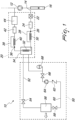
- Figure 1 schematically illustrates a first embodiment of the system for deicing the external evaporator of the heat pump system according to the invention, generally designated by the reference numeral 10, if such system is integrated directly in the heat pump system, for example a conventional air conditioning system.
- the compressor 12 of the heat pump system compresses the cooling fluid in the form of a gas and puts it into the circuit, activating the circulation thereof in the gaseous state, at high pressure and at high temperature.
- a first portion of coolant gas is redirected to a secondary refrigeration circuit 20, connected in input and in output to the heat pump system, while a second portion of coolant gas proceeds along the normal primary refrigeration circuit of the heat pump system, shown here in a simplified representation, for example a conventional conditioning system which comprises internal radiators 16 installed in the rooms of the building to be heated.
- the first portion of coolant gas which as mentioned is redirected to the secondary refrigeration circuit 20, proceeds toward a two-way, two-position opening control valve 22, which is adapted to activate (open) or deactivate (closed) the deicing system 10 as a function of the values of the external and internal ambient temperature, of the input and output temperature of the coolant gas, and of the humidity in contact with the external evaporator of the system, not shown here, such values being measured by adapted probes or sensors, and also as a function of the needs of the context.
- the coolant in the gaseous phase enters a gas accumulator 24.
- the coolant gas arrives at a three-way, two-position first redirection valve 26, by way of which it is redirected into a by-pass 28 in the direction of a first heat exchanger 32, preferably made of copper, where the change of state of the coolant from gaseous to liquid takes place.
- the heat of the coolant gas is transferred to a deicing fluid, such as for example water, which is stored in a tank 34, which therefore acts as a condenser, the first exchanger 32 being immersed, preferably totally, in the aforementioned deicing fluid.
- a deicing fluid such as for example water
- the latter At the output from the first exchanger 32, i.e. as a consequence of the transfer of heat from the coolant, the latter is therefore in the liquid phase, at average temperature and average pressure.
- Such liquid coolant is then conveyed to a second redirection valve 36, also three-way and two-position, which directs it toward a second heat exchanger 40, constituted preferably by a copper capillary tube, where the coolant passes from the liquid state to the vapor state.
- a second redirection valve 36 also three-way and two-position, which directs it toward a second heat exchanger 40, constituted preferably by a copper capillary tube, where the coolant passes from the liquid state to the vapor state.
- the coolant After passing through the second heat exchanger 40, the coolant, which is now in the vapor state, enters a liquid accumulator 42, and proceeds toward a liquid separator 44.
- the coolant is ready to be sucked in once again by the compressor 12 and to resume its path from the start, in gaseous form.
- a closed-circuit deicing circuit 50 is formed, which is therefore connected in input and in output to the tank 34.
- the heated water is conveyed, through the delivery pipe 52, toward a two-way, two-position first flow control valve 54, which if open allows it to enter a heat exchanger 56 and release the heat energy that was previously acquired.
- the water dissipates the heat in the form of hot air toward such external evaporator, thus preventing any formation of frost or ice and keeping the conventional air conditioning system 16 stable without arrests and swings in operation.
- the cooled water After exiting from the exchanger 56, the cooled water enters the return pipe 60 and arrives at a two-way, two-position second flow control valve 58, which allows it (open) or denies it (closed) the passage.
- the cooled water passes through a non-return valve or check valve 62, a circulation pump 64, a third flow control valve 66, also two-way, two-position, and finally it reenters the storage tank 34 so that it can be heated again and reintroduced into circulation in the deicing circuit 50.
- the deicing circuit 50 advantageously comprises an expansion vessel 68, which performs the function of containing the pressure variations of the circuit, thus preventing hazardous sudden changes and water hammers, which otherwise would have to be absorbed by the piping and by the rest of the system.
- system 10 for deicing the external evaporator in a heat pump system can also operate in cooling mode, so as to exchange cooled water in the exchanger 56 and favor the maintenance of low temperatures of the exchanger or external radiator, which in this case operates as a condenser.
- the cooling fluid first passes through a third heat exchanger 30, which is constituted preferably by a copper capillary tube, in place of the by-pass 28; and then through a by-pass 38 in place of the second heat exchanger 40.
- a third heat exchanger 30 which is constituted preferably by a copper capillary tube, in place of the by-pass 28; and then through a by-pass 38 in place of the second heat exchanger 40.
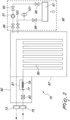
- Figure 2 schematically illustrates a second embodiment of the system for deicing the external evaporator of the heat pump system according to the invention, generally designated by the reference numeral 70, if such system is connected externally to a heat pump system, for example a conventional conditioning system.
- the deicing system 70 is constituted by a prefabricated kit, assembled in a single enclosure.
- the cooling fluid in the gaseous state arrives from the heat pump system as if such deicing system 70 in kit form were a normal internal exchanger, with the difference that it has a deicing fluid, such as for example water, and not air, as the exchange element.
- a deicing fluid such as for example water, and not air
- the secondary refrigeration circuit 80 of the deicing system 70 can be connected in input and in output to the existing heat pump system by way of two brass threadings of the specified diameters, to which the deicing system 70 is connected by way of sealing elements 73 and 75.
- the coolant gas arrives at the input connector 75 and, once inside the secondary refrigeration circuit 80, meets a two-way, two-position opening control valve 83, which is adapted to activate (open) or deactivate (closed) the deicing system 70 as a function of the values of the external and internal ambient temperature, of the input and output temperature of the coolant gas, and of the humidity in contact with the external evaporator of the system, not shown here, such values being measured by adapted probes or sensors, and also as a function of the needs of the context.
- the coolant gas proceeds toward a three-way, two-position redirection valve 77, which makes it possible, according to the mode that has been set (heating or cooling), to direct the coolant gas directly toward a heat exchanger 85, preferably made of copper, through the by-pass 81; or to redirect the coolant gas toward a heat exchanger 79, which is constituted preferably by a copper capillary tube, and therefore evaporate the gas before the heat exchanger 85.
- a storage tank 87 contains a deicing fluid, such as for example water, and internally comprises the heat exchanger 85 immersed, preferably totally, in the aforementioned deicing fluid.
- a deicing fluid such as for example water
- the water contained in the tank 87 is heated; while in the second case, i.e. with the passage of the coolant gas through the heat exchanger 79, the water contained in the tank 87 is cooled.
- a deicing circuit 90 connected in input and in output to the tank 87, the heated water is withdrawn by way of a circulation pump 91, which is connected to its ends to flow control valves 89 and 93.
- the deicing circuit 90 also comprises a heat exchanger 97, which is positioned proximate to the external evaporator of the system, and is connected to the flow control valves 95 for the delivery and 99 for the return.
- the water dissipates the heat in the form of hot air toward such external evaporator, thus preventing any formation of frost or ice and keeping the conventional air conditioning system stable without arrests and swings in operation.
- the deicing circuit 90 advantageously comprises an expansion vessel 101, which performs the function of containing the pressure variations of the circuit, thus preventing hazardous sudden changes and water hammers, which otherwise would have to be absorbed by the piping and by the rest of the system.
- the system for deicing the external evaporator in a heat pump system further comprises an electronic control system that continuously analyzes the working conditions (external temperature, external humidity etc.) of the external evaporating exchanger and which, if conditions are detected that are indicative of the formation of frost or ice, sends a command to send the heat exchangers 56 and 97, which are adapted to preheat air, a sufficient quantity of heat for melting.
- an electronic control system that continuously analyzes the working conditions (external temperature, external humidity etc.) of the external evaporating exchanger and which, if conditions are detected that are indicative of the formation of frost or ice, sends a command to send the heat exchangers 56 and 97, which are adapted to preheat air, a sufficient quantity of heat for melting.
- the principle on which the system for deicing the external evaporator in a heat pump system according to the invention is based is different from the one currently in use, in which all the heat produced by the operation of the heat pump is dispersed into the environment.
- a part of the heat produced by the heat pump during its operation is not dispersed into the environment, but is accumulated, by way of the deicing fluid contained in the storage tanks 34 and 87, and used, if and when needed, to heat the external cold air in contact with the heat exchangers 56 and 97, which prevents the formation of frost or of ice on the surface of the external evaporator of the system.
- the system for deicing the external evaporator in a heat pump system thus conceived makes it possible to overcome the qualitative limitations of the known art, in that it makes it possible to completely substitute the step of deicing during the operation of the system, i.e. to avoid the periodic execution of deicing cycles that interrupt the operation of the system in heating mode, consequently avoiding frequent cooling fluid cycle inversions and repeated preheating operations.
- the system for deicing the external evaporator of the heat pump system according to the invention is more efficient in energy terms, since it needs less energy in order to obtain the same level of heating, and is more convenient in economic terms, in that a significant reduction in the energy costs is obtained for a modest increase in the production costs of the system.
- Another advantage of the system for deicing the external evaporator of the heat pump system according to the invention consists in that it makes it possible to spare the apparatus from conditions of excessive stress, in this manner ensuring greater reliability of the mechanical and electrical parts, especially over the long term of service, and a consequent reduction of the number of maintenance operations necessary.
- Another advantage of the system for deicing the external evaporator of the heat pump system according to the invention consists in that it makes it possible to increase performance in terms of absorptions, both in heating mode (SCOP) and in cooling mode (SEER).
- the system for deicing the external evaporator of the heat pump system has been devised in particular for use in conditioning systems adapted to heat or cool residential, commercial or industrial buildings, it can also be used, more generally, for use in any apparatus or system that comprises a heat pump machine, the external evaporator of which is subject to the formation on its surface of frost or ice, in particular in heating mode when it operates as an evaporator.
- the materials used may be any according to requirements and to the state of the art.
Landscapes
- Engineering & Computer Science (AREA)
- Physics & Mathematics (AREA)
- Mechanical Engineering (AREA)
- Thermal Sciences (AREA)
- General Engineering & Computer Science (AREA)
- Chemical & Material Sciences (AREA)
- Combustion & Propulsion (AREA)
- Other Air-Conditioning Systems (AREA)
- Defrosting Systems (AREA)
Applications Claiming Priority (2)
| Application Number | Priority Date | Filing Date | Title |
|---|---|---|---|
| ITUB2015A003364A ITUB20153364A1 (it) | 2015-09-03 | 2015-09-03 | Sistema per lo sbrinamento dell?evaporatore esterno in un impianto a pompa di calore. |
| PCT/EP2016/070642 WO2017037189A1 (en) | 2015-09-03 | 2016-09-01 | System for deicing the external evaporator in a heat pump system |
Publications (3)
| Publication Number | Publication Date |
|---|---|
| EP3344932A1 EP3344932A1 (en) | 2018-07-11 |
| EP3344932C0 EP3344932C0 (en) | 2024-03-06 |
| EP3344932B1 true EP3344932B1 (en) | 2024-03-06 |
Family
ID=54843946
Family Applications (1)
| Application Number | Title | Priority Date | Filing Date |
|---|---|---|---|
| EP16763479.9A Active EP3344932B1 (en) | 2015-09-03 | 2016-09-01 | A heat pump system |
Country Status (5)
| Country | Link |
|---|---|
| US (1) | US10557655B2 (it) |
| EP (1) | EP3344932B1 (it) |
| CN (1) | CN108027177B (it) |
| IT (1) | ITUB20153364A1 (it) |
| WO (1) | WO2017037189A1 (it) |
Families Citing this family (1)
| Publication number | Priority date | Publication date | Assignee | Title |
|---|---|---|---|---|
| CN111023664B (zh) * | 2019-12-30 | 2021-09-17 | 常州大学 | 一种带低温相变的协同控制车载冷柜除冰与辅冷复合系统 |
Family Cites Families (12)
| Publication number | Priority date | Publication date | Assignee | Title |
|---|---|---|---|---|
| US5099651A (en) * | 1989-09-05 | 1992-03-31 | Gas Research Institute | Gas engine driven heat pump method |
| US6311507B1 (en) * | 2000-10-19 | 2001-11-06 | Carter Burgess, Incorporated | Refrigeration system with minimum pre-set condensing pressure |
| US6708510B2 (en) * | 2001-08-10 | 2004-03-23 | Thermo King Corporation | Advanced refrigeration system |
| US7478540B2 (en) * | 2001-10-26 | 2009-01-20 | Brooks Automation, Inc. | Methods of freezeout prevention and temperature control for very low temperature mixed refrigerant systems |
| CN1884940B (zh) * | 2005-06-22 | 2012-02-29 | 海尔集团公司 | 发动机驱动式空调机的除霜装置 |
| JP4856489B2 (ja) * | 2006-07-31 | 2012-01-18 | サンデン株式会社 | 給湯装置 |
| KR100970870B1 (ko) * | 2008-08-26 | 2010-07-16 | 진금수 | 히트 펌프 시스템 |
| CN201344676Y (zh) * | 2009-02-12 | 2009-11-11 | 珠海格力电器股份有限公司 | 带有旁通过冷的热泵型空调器 |
| US8091372B1 (en) * | 2009-03-11 | 2012-01-10 | Mark Ekern | Heat pump defrost system |
| US9464840B2 (en) * | 2013-06-05 | 2016-10-11 | Hill Phoenix, Inc. | Gas defrosting system for refrigeration units using fluid cooled condensers |
| US9939181B2 (en) * | 2013-12-11 | 2018-04-10 | Trane International Inc. | Micro-combined heat and power heat pump defrost procedure |
| US20150354837A1 (en) * | 2014-06-09 | 2015-12-10 | Anit Asthana | Portable air conditioner with water evaporator heat exchange system |
-
2015
- 2015-09-03 IT ITUB2015A003364A patent/ITUB20153364A1/it unknown
-
2016
- 2016-09-01 EP EP16763479.9A patent/EP3344932B1/en active Active
- 2016-09-01 WO PCT/EP2016/070642 patent/WO2017037189A1/en active Application Filing
- 2016-09-01 US US15/757,619 patent/US10557655B2/en active Active
- 2016-09-01 CN CN201680051042.5A patent/CN108027177B/zh active Active
Also Published As
| Publication number | Publication date |
|---|---|
| WO2017037189A1 (en) | 2017-03-09 |
| CN108027177B (zh) | 2021-04-09 |
| ITUB20153364A1 (it) | 2017-03-03 |
| EP3344932C0 (en) | 2024-03-06 |
| CN108027177A (zh) | 2018-05-11 |
| US20180252450A1 (en) | 2018-09-06 |
| US10557655B2 (en) | 2020-02-11 |
| EP3344932A1 (en) | 2018-07-11 |
Similar Documents
| Publication | Publication Date | Title |
|---|---|---|
| KR102471584B1 (ko) | 증기압축냉동 시스템의 리버스-사이클 해동을 위한 상변환 물질 기반의 증진법 | |
| CN110325804B (zh) | 用于控制制冷系统的系统和方法 | |
| US10302343B2 (en) | Defrost system for refrigeration apparatus, and cooling unit | |
| USRE29966E (en) | Heat pump with frost-free outdoor coil | |
| CN107076477B (zh) | 用于自由和积极除霜的系统和方法 | |
| US20140230477A1 (en) | Hot water supply air conditioning system | |
| WO2014054178A1 (ja) | ヒートポンプ装置 | |
| US11262114B2 (en) | System for deicing an external evaporator for heat pump systems | |
| EP1630497B1 (en) | Cooling plant for a fluid with control of variables | |
| EP3344932B1 (en) | A heat pump system | |
| EP3594588B1 (en) | Geothermal heat pump device | |
| KR101079230B1 (ko) | 이슬맺힘 방지장치가 포함된 히트펌프 시스템 및 이의 제어방법 | |
| CN204084856U (zh) | 一种双温热泵热水系统 | |
| WO2005103586A2 (en) | Heat pump | |
| JP2006275449A (ja) | 蓄熱式空調装置 | |
| CN110567208A (zh) | 机组防冻装置、空调机组及空调机组控制方法 | |
| KR20140097858A (ko) | 히트펌프 | |
| CN105605839A (zh) | 冰箱及其除霜系统 | |
| TWI554735B (zh) | Heat exchange system with automatic defrost function | |
| PH12013000264B1 (en) | Refrigerating machine | |
| JPS63180045A (ja) | 暖冷房機 | |
| ITBA20090028A1 (it) | Impianto di climatizzazionemultifunzione | |
| JPS6399467A (ja) | 暖冷房機 |
Legal Events
| Date | Code | Title | Description |
|---|---|---|---|
| STAA | Information on the status of an ep patent application or granted ep patent |
Free format text: STATUS: THE INTERNATIONAL PUBLICATION HAS BEEN MADE |
|
| PUAI | Public reference made under article 153(3) epc to a published international application that has entered the european phase |
Free format text: ORIGINAL CODE: 0009012 |
|
| STAA | Information on the status of an ep patent application or granted ep patent |
Free format text: STATUS: REQUEST FOR EXAMINATION WAS MADE |
|
| 17P | Request for examination filed |
Effective date: 20180327 |
|
| AK | Designated contracting states |
Kind code of ref document: A1 Designated state(s): AL AT BE BG CH CY CZ DE DK EE ES FI FR GB GR HR HU IE IS IT LI LT LU LV MC MK MT NL NO PL PT RO RS SE SI SK SM TR |
|
| AX | Request for extension of the european patent |
Extension state: BA ME |
|
| DAV | Request for validation of the european patent (deleted) | ||
| DAX | Request for extension of the european patent (deleted) | ||
| STAA | Information on the status of an ep patent application or granted ep patent |
Free format text: STATUS: EXAMINATION IS IN PROGRESS |
|
| STAA | Information on the status of an ep patent application or granted ep patent |
Free format text: STATUS: EXAMINATION IS IN PROGRESS |
|
| 17Q | First examination report despatched |
Effective date: 20211020 |
|
| GRAP | Despatch of communication of intention to grant a patent |
Free format text: ORIGINAL CODE: EPIDOSNIGR1 |
|
| STAA | Information on the status of an ep patent application or granted ep patent |
Free format text: STATUS: GRANT OF PATENT IS INTENDED |
|
| INTG | Intention to grant announced |
Effective date: 20230928 |
|
| GRAS | Grant fee paid |
Free format text: ORIGINAL CODE: EPIDOSNIGR3 |
|
| GRAA | (expected) grant |
Free format text: ORIGINAL CODE: 0009210 |
|
| STAA | Information on the status of an ep patent application or granted ep patent |
Free format text: STATUS: THE PATENT HAS BEEN GRANTED |
|
| AK | Designated contracting states |
Kind code of ref document: B1 Designated state(s): AL AT BE BG CH CY CZ DE DK EE ES FI FR GB GR HR HU IE IS IT LI LT LU LV MC MK MT NL NO PL PT RO RS SE SI SK SM TR |
|
| REG | Reference to a national code |
Ref country code: GB Ref legal event code: FG4D |
|
| REG | Reference to a national code |
Ref country code: CH Ref legal event code: EP |
|
| REG | Reference to a national code |
Ref country code: IE Ref legal event code: FG4D |
|
| REG | Reference to a national code |
Ref country code: DE Ref legal event code: R096 Ref document number: 602016086158 Country of ref document: DE |
|
| U01 | Request for unitary effect filed |
Effective date: 20240403 |