EP3344925B1 - Method and system for operating a thermal energy exchanger - Google Patents
Method and system for operating a thermal energy exchanger Download PDFInfo
- Publication number
- EP3344925B1 EP3344925B1 EP16751208.6A EP16751208A EP3344925B1 EP 3344925 B1 EP3344925 B1 EP 3344925B1 EP 16751208 A EP16751208 A EP 16751208A EP 3344925 B1 EP3344925 B1 EP 3344925B1
- Authority
- EP
- European Patent Office
- Prior art keywords
- thermal energy
- thermal
- energy exchanger
- air
- normalized
- Prior art date
- Legal status (The legal status is an assumption and is not a legal conclusion. Google has not performed a legal analysis and makes no representation as to the accuracy of the status listed.)
- Active
Links
- 238000000034 method Methods 0.000 title claims description 34
- 238000012546 transfer Methods 0.000 claims description 322
- 239000012530 fluid Substances 0.000 claims description 191
- 238000005259 measurement Methods 0.000 claims description 65
- 238000010606 normalization Methods 0.000 claims description 15
- 238000004590 computer program Methods 0.000 claims description 14
- 238000001514 detection method Methods 0.000 claims description 5
- 238000012545 processing Methods 0.000 claims description 5
- 230000001052 transient effect Effects 0.000 claims description 2
- 230000000977 initiatory effect Effects 0.000 claims 1
- 238000004891 communication Methods 0.000 description 11
- 238000010586 diagram Methods 0.000 description 9
- 230000001276 controlling effect Effects 0.000 description 6
- 238000001816 cooling Methods 0.000 description 6
- XLYOFNOQVPJJNP-UHFFFAOYSA-N water Substances O XLYOFNOQVPJJNP-UHFFFAOYSA-N 0.000 description 4
- 238000010438 heat treatment Methods 0.000 description 3
- 230000007774 longterm Effects 0.000 description 3
- 238000004378 air conditioning Methods 0.000 description 2
- 238000013459 approach Methods 0.000 description 2
- 230000001419 dependent effect Effects 0.000 description 2
- 238000010295 mobile communication Methods 0.000 description 2
- 230000001105 regulatory effect Effects 0.000 description 2
- 230000006399 behavior Effects 0.000 description 1
- 239000002131 composite material Substances 0.000 description 1
- 238000013500 data storage Methods 0.000 description 1
- 238000013461 design Methods 0.000 description 1
- 230000007613 environmental effect Effects 0.000 description 1
- 238000009434 installation Methods 0.000 description 1
- 238000005457 optimization Methods 0.000 description 1
- 239000003507 refrigerant Substances 0.000 description 1
- 230000009466 transformation Effects 0.000 description 1
- 238000009423 ventilation Methods 0.000 description 1
Images


Classifications
-
- F—MECHANICAL ENGINEERING; LIGHTING; HEATING; WEAPONS; BLASTING
- F24—HEATING; RANGES; VENTILATING
- F24F—AIR-CONDITIONING; AIR-HUMIDIFICATION; VENTILATION; USE OF AIR CURRENTS FOR SCREENING
- F24F11/00—Control or safety arrangements
- F24F11/30—Control or safety arrangements for purposes related to the operation of the system, e.g. for safety or monitoring
- F24F11/46—Improving electric energy efficiency or saving
-
- F—MECHANICAL ENGINEERING; LIGHTING; HEATING; WEAPONS; BLASTING
- F24—HEATING; RANGES; VENTILATING
- F24F—AIR-CONDITIONING; AIR-HUMIDIFICATION; VENTILATION; USE OF AIR CURRENTS FOR SCREENING
- F24F11/00—Control or safety arrangements
- F24F11/50—Control or safety arrangements characterised by user interfaces or communication
- F24F11/56—Remote control
- F24F11/58—Remote control using Internet communication
-
- F—MECHANICAL ENGINEERING; LIGHTING; HEATING; WEAPONS; BLASTING
- F24—HEATING; RANGES; VENTILATING
- F24F—AIR-CONDITIONING; AIR-HUMIDIFICATION; VENTILATION; USE OF AIR CURRENTS FOR SCREENING
- F24F11/00—Control or safety arrangements
- F24F11/62—Control or safety arrangements characterised by the type of control or by internal processing, e.g. using fuzzy logic, adaptive control or estimation of values
- F24F11/63—Electronic processing
- F24F11/64—Electronic processing using pre-stored data
-
- F—MECHANICAL ENGINEERING; LIGHTING; HEATING; WEAPONS; BLASTING
- F24—HEATING; RANGES; VENTILATING
- F24F—AIR-CONDITIONING; AIR-HUMIDIFICATION; VENTILATION; USE OF AIR CURRENTS FOR SCREENING
- F24F11/00—Control or safety arrangements
- F24F11/62—Control or safety arrangements characterised by the type of control or by internal processing, e.g. using fuzzy logic, adaptive control or estimation of values
- F24F11/63—Electronic processing
- F24F11/65—Electronic processing for selecting an operating mode
-
- F—MECHANICAL ENGINEERING; LIGHTING; HEATING; WEAPONS; BLASTING
- F24—HEATING; RANGES; VENTILATING
- F24F—AIR-CONDITIONING; AIR-HUMIDIFICATION; VENTILATION; USE OF AIR CURRENTS FOR SCREENING
- F24F11/00—Control or safety arrangements
- F24F11/70—Control systems characterised by their outputs; Constructional details thereof
- F24F11/72—Control systems characterised by their outputs; Constructional details thereof for controlling the supply of treated air, e.g. its pressure
- F24F11/74—Control systems characterised by their outputs; Constructional details thereof for controlling the supply of treated air, e.g. its pressure for controlling air flow rate or air velocity
-
- F—MECHANICAL ENGINEERING; LIGHTING; HEATING; WEAPONS; BLASTING
- F24—HEATING; RANGES; VENTILATING
- F24F—AIR-CONDITIONING; AIR-HUMIDIFICATION; VENTILATION; USE OF AIR CURRENTS FOR SCREENING
- F24F11/00—Control or safety arrangements
- F24F11/70—Control systems characterised by their outputs; Constructional details thereof
- F24F11/80—Control systems characterised by their outputs; Constructional details thereof for controlling the temperature of the supplied air
- F24F11/83—Control systems characterised by their outputs; Constructional details thereof for controlling the temperature of the supplied air by controlling the supply of heat-exchange fluids to heat-exchangers
- F24F11/84—Control systems characterised by their outputs; Constructional details thereof for controlling the temperature of the supplied air by controlling the supply of heat-exchange fluids to heat-exchangers using valves
-
- G—PHYSICS
- G05—CONTROLLING; REGULATING
- G05B—CONTROL OR REGULATING SYSTEMS IN GENERAL; FUNCTIONAL ELEMENTS OF SUCH SYSTEMS; MONITORING OR TESTING ARRANGEMENTS FOR SUCH SYSTEMS OR ELEMENTS
- G05B17/00—Systems involving the use of models or simulators of said systems
- G05B17/02—Systems involving the use of models or simulators of said systems electric
-
- F—MECHANICAL ENGINEERING; LIGHTING; HEATING; WEAPONS; BLASTING
- F24—HEATING; RANGES; VENTILATING
- F24F—AIR-CONDITIONING; AIR-HUMIDIFICATION; VENTILATION; USE OF AIR CURRENTS FOR SCREENING
- F24F2110/00—Control inputs relating to air properties
- F24F2110/10—Temperature
-
- F—MECHANICAL ENGINEERING; LIGHTING; HEATING; WEAPONS; BLASTING
- F24—HEATING; RANGES; VENTILATING
- F24F—AIR-CONDITIONING; AIR-HUMIDIFICATION; VENTILATION; USE OF AIR CURRENTS FOR SCREENING
- F24F2110/00—Control inputs relating to air properties
- F24F2110/30—Velocity
-
- F—MECHANICAL ENGINEERING; LIGHTING; HEATING; WEAPONS; BLASTING
- F24—HEATING; RANGES; VENTILATING
- F24F—AIR-CONDITIONING; AIR-HUMIDIFICATION; VENTILATION; USE OF AIR CURRENTS FOR SCREENING
- F24F2140/00—Control inputs relating to system states
-
- F—MECHANICAL ENGINEERING; LIGHTING; HEATING; WEAPONS; BLASTING
- F24—HEATING; RANGES; VENTILATING
- F24F—AIR-CONDITIONING; AIR-HUMIDIFICATION; VENTILATION; USE OF AIR CURRENTS FOR SCREENING
- F24F2140/00—Control inputs relating to system states
- F24F2140/20—Heat-exchange fluid temperature
Definitions
- the present invention relates to a method and a control system for operating a thermal energy exchanger. Specifically, the present invention relates to a method and a control system for operating a thermal energy exchanger of an HVAC (Heating, Ventilating, and Air Conditioning) system for exchanging thermal energy between a thermal transfer fluid, flowing through the thermal energy exchanger in a fluid conduit, and air, being conducted through the thermal energy exchanger in an air duct.
- HVAC Heating, Ventilating, and Air Conditioning
- thermal energy exchangers of an HVAC system By regulating the flow of fluid through thermal energy exchangers of an HVAC system, it is possible to adjust the amount of energy exchanged by the thermal energy exchangers, e.g. to adjust the amount of energy delivered by a heat exchanger to heat or cool a room in a building or the amount of energy drawn by a chiller for cooling purposes. While the fluid transport through the fluid circuit of the HVAC system is driven by one or more pumps, the flow is typically regulated by varying the opening or position of valves, e.g. manually or by way of actuators. It is known that the efficiency of thermal energy exchangers is reduced at high flow rates where the fluid rushes at an increased rate through the thermal energy exchangers, without resulting in a significant increase in energy exchange.
- US 6,352,106 describes a self-balancing valve having a temperature sensor for measuring the temperature of a fluid passing through the valve. According to US 6,352,106 , the range and thus the maximum opening of the valve are adjusted dynamically, depending on the measured temperature.
- the opening of the valve is modulated based on a stored temperature threshold value, the current fluid temperature, and a position command signal from a load controller. Specifically, the opening range of the valve is set periodically by a position controller, based on a temperature threshold value stored at the position controller, the current fluid temperature, and the difference between the previously measured fluid temperature and the current fluid temperature.
- US 6,352,106 further describes an alternative embodiment with two temperature sensors, one placed on the supply line and the other one placed on the return line, for measuring the actual differential temperature over the load, i.e. the thermal energy exchanger.
- the threshold temperature is a threshold differential temperature across the load determined by system requirements of the load.
- US 6,352,106 describes controlling the flow based on a change in fluid temperature or a change in a differential temperature over the load. Accordingly, the flow is controlled based on a comparison of determined temperature changes to fixed threshold temperatures or threshold differential temperatures, respectively, which must be predefined and stored at the valve's position controller.
- WO 2014/183868 A2 discloses a method of controlling opening of a valve in an HVAC system to regulate the flow of a fluid through a thermal energy exchanger of the HVAC system.
- the above-mentioned objects are particularly achieved in that, to operate a thermal energy exchanger for exchanging thermal energy between a thermal transfer fluid, flowing through the thermal energy exchanger in a fluid conduit, and air, being conducted through the thermal energy exchanger in an air duct, a plurality of measurement data sets are recorded in a control system, particularly in an HVAC control system.
- Each of the measurement data sets includes, for a different point in time, data values defining a normalized energy transfer which represents the thermal energy transferred in the thermal energy exchanger, from the thermal transfer fluid to the air, normalized by one or more normalization variables including at least one air side variable.
- the control system calculates for each of the measurement data sets a normalized data point defined by the normalized energy transfer.
- the control system determines for the thermal energy exchanger a characteristic energy transfer curve which fits the normalized data points.
- Normalizing the energy transfer that is based on "raw" measurement data makes it possible to operate the thermal energy exchanger more efficiently over a wider range of changing operating and environment conditions, because the normalized data makes it possible to determine better efficiency thresholds that are more suitable and applicable to variable operating and environment conditions. Consequently, it is possible to prevent the thermal energy exchanger or its coil(s) from reaching saturation by limiting or setting the flow rate of the thermal transfer fluid, the flow of air, and/or the temperature of the thermal transfer fluid with more appropriate fixed or variable thresholds.
- the control system determines a boundary for efficient thermal energy transfer in the thermal energy exchanger between the thermal transfer fluid and the air.
- the boundary defines an efficient area, where on the characteristic energy transfer curve the thermal energy transfer is more energy efficient than on the characteristic energy transfer curve outside the efficient area.
- the control system keeps the thermal energy exchanger operating within said efficient area.
- the boundary defines the efficient area such that on the characteristic energy transfer curve the thermal energy transfer increases comparably more with an increasing flow of thermal transfer fluid, than with an increasing flow of thermal transfer on the characteristic energy transfer curve outside the efficient area.
- control system controls operating parameters to maintain operation of the thermal energy exchanger within said efficient area, the operating parameters including the flow of thermal transfer fluid through the thermal energy exchanger, the flow of air through the thermal energy exchanger, and/or the temperature of the thermal transfer fluid entering the thermal energy exchanger.
- control system controls operating parameters to maintain operation of the thermal energy exchanger on the characteristic energy transfer curve.
- the operating parameters comprise: the flow of thermal transfer fluid through the thermal energy exchanger, the flow of air through the thermal energy exchanger, and/or the temperature of the thermal transfer fluid entering the thermal energy exchanger.
- each of the measurement data sets includes an air inlet enthalpy value, an air outlet enthalpy value, a thermal transfer fluid inlet enthalpy value, and a thermal transfer fluid outlet enthalpy value.
- the control system calculates the normalized energy transfer for each of the normalized data points, using the air inlet enthalpy value, the air outlet enthalpy value, the thermal transfer fluid inlet enthalpy value, and the thermal transfer fluid outlet enthalpy value.
- each of the measurement data sets includes a temperature value of the air entering the thermal energy exchanger, a temperature value of the air exiting the thermal energy exchanger, a humidity value of the air entering the thermal energy exchanger, a humidity value of the air exiting the thermal energy exchanger, a temperature value of the thermal transfer fluid entering the thermal energy exchanger, and a temperature value of the thermal transfer fluid exiting the thermal energy exchanger.
- the control system calculates the normalized energy transfer for each of the normalized data points, using the temperature value of the air entering the thermal energy exchanger, the temperature value of the air exiting the thermal energy exchanger, the humidity value of the air entering the thermal energy exchanger, the humidity value of the air exiting the thermal energy exchanger, the temperature value of the thermal transfer fluid entering the thermal energy exchanger, and the temperature value of the thermal transfer fluid exiting the thermal energy exchanger.
- each of the measurement data sets includes for the different points in time the flow of thermal transfer fluid through the thermal energy exchanger and the flow of air through the thermal energy exchanger.
- the control system calculates for each of the normalized data points a normalized flow of thermal transfer fluid through the fluid conduit normalized by the flow of air.
- each of the measurement data sets includes data values defining a log mean enthalpy difference from an inlet enthalpy difference, of the air entering the thermal energy exchanger and the thermal transfer fluid entering the thermal energy exchanger, and an outlet enthalpy difference, of the air exiting the thermal energy exchanger and the thermal transfer fluid exiting the thermal energy exchanger.
- the control system calculates the normalized energy transfer for each of the normalized data points using the log mean enthalpy difference.
- each of the measurement data sets includes the flow of air through the thermal energy exchanger.
- the control system calculates the normalized energy transfer for each of the normalized data points using the flow of air through the thermal energy exchanger.
- each of the measurement data sets includes the flow of thermal transfer fluid through the thermal energy exchanger.
- the control system calculates the normalized energy transfer for each of the normalized data points using the flow of thermal transfer fluid through the thermal energy exchanger.
- each of the measurement data sets includes for the different points in time data values defining an air side enthalpy difference of the air entering the thermal energy exchanger and the air exiting the thermal energy exchanger, and data values defining an enthalpy difference on the thermal transfer fluid side of the thermal transfer fluid entering the thermal energy exchanger and the thermal transfer fluid exiting the thermal energy exchanger.
- the control system calculates for each of the normalized data points a value representative of the normalized flow, from the air side enthalpy difference and the enthalpy difference on the thermal transfer fluid side.
- each of the measurement data sets includes data values defining a log mean enthalpy difference from an inlet enthalpy difference, of the air entering the thermal energy exchanger and the thermal transfer fluid entering the thermal energy exchanger, and an outlet enthalpy difference, of the air exiting the thermal energy exchanger and the thermal transfer fluid exiting the thermal energy exchanger.
- the control system calculates the normalized energy transfer for each of the normalized data points using the air side enthalpy difference and the log mean enthalpy difference.
- each of the measurement data sets includes data values defining a log mean enthalpy difference from an inlet enthalpy difference, of the air entering the thermal energy exchanger and the thermal transfer fluid entering the thermal energy exchanger, and an outlet enthalpy difference, of the air exiting the thermal energy exchanger and the thermal transfer fluid exiting the thermal energy exchanger.
- the control system calculates the normalized energy transfer for each of the normalized data points using the enthalpy difference on the thermal transfer fluid side and the log mean enthalpy difference.
- each of the measurement data sets includes data values for determining a sensible part and a latent part of the thermal energy transferred in the thermal energy exchanger, from the thermal transfer fluid to the air.
- the control system calculates a normalized sensible part and a normalized latent part, using one or more normalization variables.
- the control system further determines boundaries for efficient thermal energy transfer in the thermal energy exchanger between the thermal transfer fluid and the air separately for the normalized sensible part and the normalized latent part.
- the control system keeps the thermal energy exchanger operating within efficient areas defined by said boundaries.
- each of the measurement data sets includes a temperature value of the thermal transfer fluid entering the thermal energy exchanger, and a temperature value of the air entering the thermal energy exchanger.
- the control system calculates the normalized sensible part of the thermal energy transferred in the thermal energy exchanger using the difference of the temperature value of the thermal transfer fluid entering the thermal energy exchanger and the temperature value of the air entering the thermal energy exchanger.
- each of the measurement data sets includes a temperature value of the thermal transfer fluid entering the thermal energy exchanger.
- the control system calculates the normalized latent part of the thermal energy transferred in the thermal energy exchanger using the difference of the temperature value of a dew point temperature of the air and temperature the thermal transfer fluid entering the thermal energy exchanger.
- each of the measurement data sets includes a temperature value of the thermal transfer fluid entering the thermal energy exchanger, an absolute humidity value of the air entering the thermal energy exchanger, and a temperature value of the thermal transfer fluid entering the thermal energy exchanger.
- the control system calculates the normalized latent part of the thermal energy transferred in the thermal energy exchanger using the difference of the absolute humidity value of the of the air entering the thermal energy exchanger and an absolute humidity value at saturation at the temperature value of the thermal transfer fluid entering the thermal energy exchanger.
- control system determining a characteristic energy transfer curve, which indicates an expected energy transfer in the thermal energy exchanger from the thermal transfer fluid to the air.
- the control system further detects a deviation of the normalized energy transfer from the expected energy transfer. Upon detection of a deviation, the control system initiates exception processing.
- control system selects a characteristic energy transfer curve from a set of different characteristic energy transfer curves, which indicate for different air side parameters an expected energy transfer in the thermal energy exchanger from the thermal transfer fluid to the air, using airside parameters included in the measurement data sets.
- control system includes in the exception processing at least one of the following steps: generating an alarm signal, selecting an alternative characteristic energy transfer curve from a set of different characteristic energy transfer curves, and determining an alternative characteristic energy transfer curve using the plurality of measurement data sets.
- the present invention also relates to a control system for operating a thermal energy exchanger for exchanging thermal energy between a thermal transfer fluid, flowing through the thermal energy exchanger in a fluid conduit, and air, being conducted through the thermal energy exchanger in an air duct.
- the control system comprises at least one processor configured to record in the control system a plurality of measurement data sets. Each of the measurement data sets includes for a different point in time data values defining a normalized energy transfer which represents the thermal energy transferred in the thermal energy exchanger, from the thermal transfer fluid to the air, normalized by one or more normalization variables including at least one air side variable.
- the processor is further configured to calculate for each of the measurement data sets a normalized data point defined by the normalized energy transfer.
- the processor is further configured to determine for the thermal energy exchanger a characteristic energy transfer curve which fits the normalized data points.
- the processor is further configured to determine a boundary for efficient thermal energy transfer in the thermal energy exchanger between the thermal transfer fluid and the air.
- the boundary defines an efficient area, where on the characteristic energy transfer curve the thermal energy transfer is more energy efficient than on the characteristic energy transfer curve outside the efficient area.
- the processor is further configured to keep the thermal energy exchanger operating within said efficient area.
- the processor is further configured to control operating parameters to maintain operation of the thermal energy exchanger on the characteristic energy transfer curve, the operating parameters comprising: the flow of thermal transfer fluid through the thermal energy exchanger, the flow of air through the thermal energy exchanger, and/or the temperature of the thermal transfer fluid entering the thermal energy exchanger.
- the processor is further configured to perform the steps of the method of operating a thermal energy exchanger.
- the present invention also relates to a computer program product comprising a non-transient computer-readable medium having stored thereon computer program code configured to control a processor of a control system for operating a thermal energy exchanger for exchanging thermal energy between a thermal transfer fluid, flowing through the thermal energy exchanger in a fluid conduit, and air, being conducted through the thermal energy exchanger in an air duct.
- the computer program code is configured to control the processor such that the processor records in the control system a plurality of measurement data sets. Each of the measurement data sets includes for a different point in time data values that define a normalized energy transfer.
- the normalized energy transfer represents the thermal energy transferred in the thermal energy exchanger, from the thermal transfer fluid to the air, normalized by one or more normalization variables including at least one air side variable.
- the computer program code is further configured to control the processor such that the processor calculates for each of the measurement data sets a normalized data point defined by the normalized energy transfer, and that the processor determines for the thermal energy exchanger a characteristic energy transfer curve which fits the normalized data points.
- the computer program code is further configured to control the processor such that the processor determines a boundary for efficient thermal energy transfer in the thermal energy exchanger between the thermal transfer fluid and the air.
- the boundary defines an efficient area, where on the characteristic energy transfer curve the thermal energy transfer is more energy efficient than on the characteristic energy transfer curve outside the efficient area.
- the computer program code is further configured to control the processor such that processor keeps the thermal energy exchanger operating within said efficient area.
- the computer program code is further configured to control the processor such that the processor controls operating parameters to maintain operation of the thermal energy exchanger on the characteristic energy transfer curve, the operating parameters comprising: the flow of thermal transfer fluid through the thermal energy exchanger, the flow of air through the thermal energy exchanger, and/or the temperature of the thermal transfer fluid entering the thermal energy exchanger.
- the computer program code is further configured to control the processor such that the processor performs the steps of the method of operating a thermal energy exchanger.
- reference numeral 10 refers to an HVAC system (Heating, Ventilation, Air Conditioning, and Cooling).
- the HVAC system 10 comprises a thermal energy exchanger 1, e.g. a heat exchanger for heating or a cooling device for cooling.
- the HVAC system 10 comprises an air transport system 3 for moving air through the thermal energy exchanger 1 and a thermal transfer fluid transport system 2 for moving thermal transfer fluid, e.g. water or a refrigerant, through the thermal energy exchanger 1.
- the air transport system 3 comprises various air side system components 30 and air ducts 300 for conducting an air flow through the thermal energy exchanger 1.
- the air side system components 30 comprise a ventilator, a controller, and an optional air flow sensor 33 for conducting and controlling the flow of air through the thermal energy exchanger 1 and ultimately through or into a room or building.
- the thermal transfer fluid transport system 2 comprises various fluid side system components 20 and fluid conduits 200 for conducting a flow of thermal transfer fluid through the thermal energy exchanger 1.
- the fluid side system components 20 comprise a motorized valve 21, a controller 22, an optional flow sensor 23, and further components, such as a pump, for conducting and controlling the flow of thermal transfer fluid through the thermal energy exchanger 1.
- the HVAC system 10 further comprises an air side inlet sensor system 11, an air side outlet sensor system 12, a fluid side inlet sensor system 13, and a fluid side outlet sensor system 14.
- the air side inlet sensor system 11 comprises an enthalpy sensor or a combination of temperature and humidity sensors configured to measure the enthalpy of the air entering the thermal energy exchanger 1.
- the air side outlet sensor system 12 comprises an enthalpy sensor or a combination of temperature and humidity sensors configured to measure or determine the enthalpy of the air exiting the thermal energy exchanger 1, respectively.
- the fluid side inlet sensor system 13 comprises a temperature sensor to determine the temperature or enthalpy of the thermal transfer fluid entering the thermal energy exchanger 1.
- the fluid side outlet sensor system 14 comprises a temperature sensor to determine the temperature or enthalpy of the thermal transfer fluid exiting the thermal energy exchanger 1.
- the sensor systems 11, 12, 13, 14 further comprise a communication module configured for wireless and/or wired data communication with the computer system 4 and/or the controller(s) 22.
- the HVAC system 10 comprises or is at least connected via a communication network 5 to a computer system 4.
- the computer system 4 comprises one or more operational computers with one or more programmable processors and a data storage system connected to the processor(s).
- the computer system 4 and the controller 22 constitute a control system, particularly a computerized HVAC control system.
- the HVAC system 10 and one or more of its controllers 22 are connected via communication network 5 to a remote computer system 4, e.g. a cloud-based computer system connected to the HVAC system 10 vie the Internet.
- the computer system 4 is a part of the HVAC system 10 and is connected via a communication network 5, such as a LAN (Local Area Network) or WLAN (Wireless Local Area Network), to one or more controllers 22 of the HVAC system 10.
- a communication network 5 such as a LAN (Local Area Network) or WLAN (Wireless Local Area Network)
- the computer system 4 is a part of the HVAC system 10 and the controller 22 is part of the computer system 4 or the controller 22 constitutes the computer system 4, respectively.
- the controller 22 includes an electronic circuit, e.g. a programmable processor, an application specific integrated circuit (ASIC), or another logic unit.
- ASIC application specific integrated circuit
- the controller 22 further comprise a communication module configured for wireless and/or wired data communication with the computer system 4, the sensor systems 11, 12, 13, 14, optional flow sensors 23, 33, and the valve 21 or its actuator, respectively, to control the flow of thermal transfer fluid.
- the controller 22 and the computer system 4 are configured (programmed) to perform various functions described later in more detail.
- the communication network 5 includes fixed communication networks or busses and/or mobile communication networks, e.g. WLAN, GSM (Global System for Mobile Communications), UMTS (Universal Mobile Telephone System), or other mobile radio networks.
- the control system 40 i.e. the computer system 4 or the controller 22, respectively, records measurement data sets obtained from the sensor systems 11-14 and the optional air side flow sensor 33 and fluid side flow sensor 23.
- the measurement data sets include for a particular point in time data values for calculating a normalized energy transfer, representing the thermal energy transferred in the thermal energy exchanger 1, from the thermal transfer fluid to the air, normalized by one or more normalization variables as will be described later in more detail.
- step S2 the computer system 4 calculates normalized data points from the measurement data sets using normalization variables which are either data values included in the measurement data sets or fixed parameter values. Normalization is the process of reducing data redundancy and increasing independency. In the present context, the normalization reduces the measurement data to a single function or curve through mathematical transformation of the data.
- the computer system 4 calculates for the normalized data points a normalized total energy transfer.
- the data values for the measurement data sets are read from the sensors by the computer system 4 or the controller 22, or reported by the sensors to the computer system 4 or the controller 22. Alternatively, the data values are collected by the controller 22 and later reported to the computer system 4. Any measurement data set recorded by the computer system 4 defines a non-normalized data point that includes data values for a particular point in time.
- the normalized total energy transfer is calculated using the log mean enthalpy difference LMED and/or the air flow ⁇ A : Q LMED ⁇ ⁇ A or Q ⁇ A
- normalized total energy transfer is calculated using the log mean enthalpy difference LMED and/or the flow of thermal transfer fluid ⁇ W : Q LMED ⁇ ⁇ W or Q ⁇ W
- step S22 the computer system 4 calculates a normalized flow of the thermal transfer fluid: ⁇ W ⁇ A
- step S23 the computer system 4 stores the normalized data point that is defined by the normalized total energy transfer Q LMED ⁇ ⁇ A (or Q ⁇ A or Q LMED ⁇ ⁇ W or Q ⁇ W or ⁇ H A LMED or ⁇ H W LMED , respectively) per normalized flow of the thermal transfer fluid ⁇ W ⁇ A (or ⁇ H A ⁇ H W , respectively).
- Figure 11 illustrates in the upper graph an example of a plurality of measurement data sets, including (non-normalized) data points P with data values of total energy transfer Q per (non-normalized) flow of thermal transfer fluid ⁇ W .
- Figure 11 illustrates in the lower graph for said example of measurement data sets the normalized data points Pn defined by the normalized total energy transfer per normalized flow of the thermal transfer fluid ⁇ W ⁇ A (or ⁇ H A ⁇ H W , respectively).
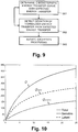
- Figure 10 illustrates for an example of the total energy transfer Q the part of the latent energy Q latent and the part of the sensible energy Q sensible dependent on the flow of thermal transfer fluid ⁇ W .
- step S211 the computer system 4 calculates the sensible Q sensible and the latent part Q latent of the total energy transfer Q.
- the computer system 4 uses the sensible heat ratio (SHR) for calculating the sensible Q sensible and the latent Q latent parts:
- Q latent Q total ⁇ Q sensible .
- step S21 2 the computer system 4 calculates for the sensible part Q sensible a normalized sensible part. Specifically, the computer system 4 calculates the normalized sensible part using the difference of the temperature T W in of the thermal transfer fluid entering the thermal energy exchanger 1 and the temperature T A in of the air entering the thermal energy exchanger 1: Q sensible T W i ⁇ T A i
- step S213 the computer system 4 calculates for the latent part Q latent a normalized latent part. Specifically, the computer system 4 calculates the normalized latent part, using the dew point temperature T dewpt of the air and inlet temperature of the thermal transfer fluid T W i : Q latent T dewpt ⁇ T W i .
- the normalized latent part is calculated, using the difference of the absolute humidity value W abs of the air entering the thermal energy exchanger 1 and an absolute humidity value at saturation W sat ( T W i ) at the temperature T W i of the thermal transfer fluid entering the thermal energy exchanger 1: Q latent W abs ⁇ W sat T W i
- Figure 12 illustrates in the upper graph an example of a plurality non-normalized data points S with data values of sensible energy transfer Q sensible per (non-normalized) flow of thermal transfer fluid ⁇ W .
- Figure 12 illustrates in the lower graph for said example of data points S the normalized data points Sn defined by the normalized sensible energy transfer Q sensible T W i ⁇ T A i per normalized flow of the thermal transfer fluid ⁇ W ⁇ A .
- Figure 13 illustrates in the upper graph an example of a plurality non-normalized data points L with data values of latent energy transfer Q latent per (non-normalized) flow of thermal transfer fluid ⁇ W .
- Figure 13 illustrates in the lower graph for said example of data points L the normalized data points Ln defined by the normalized latent energy transfer Q latent T dewpt ⁇ T W i or Q latent W abs ⁇ W sat T W i , respectively, per normalized flow of the thermal transfer fluid ⁇ W ⁇ A .
- graphs corresponding to those of Figures 11 , 12 , and 13 can be generated for scenarios where, without the use of flow sensors, the normalized total energy transfer is calculated entirely from enthalpy values and represented on the y-axis by normalized enthalpy values ⁇ H A LMED or ⁇ H W LMED , and the normalized flow of the thermal transfer fluid is represented on the x-axis by ⁇ H A ⁇ H W (the x-axis being the conventional independent axis).
- the computer system 4 determines a characteristic transfer curve for the thermal energy exchanger 1. Specifically, the computer system 4 determines the characteristic transfer curve for the thermal energy exchanger 1 using the normalized data points Pn, Sn, Ln calculated and recorded for the thermal energy exchanger 1 over an extended period of time, e.g. during a calibration or commissioning phase, of one or more days, or even several weeks or months, as a best fit for the plurality of normalized data points Pn, Sn, Ln. In the lower graph of Figure 11 the fitted characteristic transfer curve cP is indicated as a white curve running through the normalized data points Pn for normalized total energy transfer.
- the fitted characteristic transfer curve cS is indicated as a white curve running through the normalized data points Sn for normalized sensible energy transfer.
- the fitted characteristic transfer curve cL is indicated as a white curve running through the normalized data points Ln for normalized sensible energy transfer.
- the computer system 4 determines an efficiency boundary. Specifically, the computer system 4 determines the efficiency boundary bP, bS, bL (see Figures 11 , 12 , and 13 ) for the thermal energy exchanger 1 using the characteristic transfer curves cP, cS, cL or the normalized data points Pn, Sn, Ln. More specifically, the computer system 4 determines on the characteristic transfer curves cP, cS, cL boundary points BP, BS, BL (see Figures 11 , 12 , and 13 ) where the increase of the thermal energy transfer for an increase of the flow of thermal transfer fluid falls below a defined threshold value.
- the boundary bP, bS, bL is defined from the boundary points BP, BS, BL of several characteristic transfer curves cP, cS, cL determined for different sets of normalized data points, normalize separately for the total energy transfer, the latent energy transfer, and the sensible energy transfer, and/or for different values of the normalization variable(s) used, e.g.
- the log mean enthalpy difference the air flow ⁇ A , the flow of thermal transfer fluid ⁇ W , the temperature T W i of the thermal transfer fluid entering the thermal energy exchanger 1, the temperature T A i of the air entering the thermal energy exchanger 1, the dew point temperature T dewpt of the air, the absolute humidity value W abs of the air entering the thermal energy exchanger 1, and/or the absolute humidity value at saturation W sat ( T W i ) at the temperature T W i of the thermal transfer fluid entering the thermal energy exchanger 1.
- step S5 the controller 22 controls operation of the thermal energy exchanger 1 using the efficiency boundary bP, bS, bL and/or the characteristic energy transfer curve cP, cS, cL. Specifically, the controller 22 controls operation of the thermal energy exchanger 1 by controlling operating parameters of the thermal energy exchanger 1.
- the operating parameters of the thermal energy exchanger 1 include the flow of the thermal transfer fluid ⁇ W , the air flow ⁇ A , and/or the temperature T W in of the thermal transfer fluid entering the thermal energy exchanger 1.
- the controller 22 controls the operating parameters such as to maintain a normalized performance of the thermal energy exchanger 1, whereby the controller 22 keeps the thermal energy exchanger 1 operating on the (applicable) characteristic energy transfer curve cP, cS, cL. Detection of deviations from the characteristic energy transfer curve cP, cS, cL will be described later with reference to Figure 9 .
- the controller 22 further controls the operating parameters such as to optimize performance of the thermal energy exchanger 1, whereby the controller 22 keeps the thermal energy exchanger 1 operating within an efficient area aP, aS, aL defined by the efficiency boundary bP, bS, bL.
- the thermal energy transfer increases comparably more with an increasing flow of thermal transfer fluid, than with an increasing flow of thermal transfer on the characteristic energy transfer curve outside the efficient area aP, aS, aL.
- efficiency boundaries and/or efficient areas can be determined correspondingly and apply accordingly to scenarios where, without the use of flow sensors, the normalized total energy transfer is calculated entirely from enthalpy values and represented by ⁇ H A LMED or ⁇ H W LMED , and the normalized flow of the thermal transfer fluid is represented by ⁇ H A ⁇ H W .
- the controller 22 is set to control the operating parameters to maintain normalized performance according to the first aspect and/or to optimize performance according to the second aspect.
- the efficiency boundary bP, bS, bL is transferred from the computer system 4 to the controller 22.
- the computer system 4 or the controller 22 respectively, generates control signals for controlling the operating parameters.
- the control signals are transmitted from the computer system 4 or the controller 22, respectively, to a building control system, a valve 21, a damper, a pump, a fan, and/or related actuators, for example.
- the computer system 4 determines the characteristic energy transfer curve cP, cS, cL that defines the expected energy transfer, i.e. the characteristic energy transfer curve cP, cS, cL that applies to the present operating conditions of the thermal energy exchanger 1, e.g. the current flow of air ⁇ A , the current flow of thermal transfer fluid ⁇ W , or the current inlet temperature of the thermal transfer fluid T W in .
- step S62 the computer system 4 detects a deviation of the normalized energy transfer from the expected energy transfer by comparing one or more data points with the current or recent normalized energy transfer to the expected energy transfer defined by the characteristic energy transfer curve cP, cS, cL selected in step S61.
- the computer system 4 Upon detection of a deviation, in step S63, the computer system 4 initiates exception processing. Depending on the scenario, embodiment, and/or configuration, the computer system 4 generates an alarm signal, an alarm message, selects an alternative characteristic energy transfer curve from a set of different characteristic energy transfer curves, and/or determines an alternative characteristic energy transfer curve using the plurality of measurement data sets. Specifically, for long term diagnostics, where for an ongoing period of time, e.g. several days, weeks, months, or even years, the normalized energy transfer continuously deviates from the expected energy transfer, the computer system 4 establishes that the current normalized data points or the related characteristic energy transfer curve deviate from the expected energy transfer, defined by an earlier characteristic energy transfer curve, e.g.
- the computer system 4 determines a new, alternative characteristic energy transfer curve. For short or long term optimizations of exceptions or deviations, for example, if the normalized data point is detected to be within the efficient area aP, aS, aL, but below the characteristic energy transfer curve cP, cS, cL, the controller 22 controls the operating parameters such as to move the normalized data point onto the characteristic energy transfer curve cP, cS, cL. Thus, the controller 22 corrects and optimizes situations that arise from temporary disturbances or sub-optimal conditions or settings.
- the controller 22 if the normalized data point is detected to be within the efficient area aP, aS, aL, but above the characteristic energy transfer curve cP, cS, cL, the controller 22 generates an alarm or diagnostic report that indicates the detection of deviations that are caused, for example, because of sub-optimal or incorrect system setup configuration, such as arrangements of distant temperature sensors that cause excessive time lags or other settings that lead to instable system behaviours.
- the normalized total energy transfer is calculated using the temperatures T W i , T W o of the thermal transfer fluid entering or exiting the thermal energy exchanger 1, respectively, and the temperatures T A i , T Ao of the air entering or exiting the thermal energy exchanger 1, respectively, for example: Q ⁇ T W i ⁇ T W o T a i or Q ⁇ T W i ⁇ T W o T a o ⁇ T a i .
Landscapes
- Engineering & Computer Science (AREA)
- General Engineering & Computer Science (AREA)
- Chemical & Material Sciences (AREA)
- Combustion & Propulsion (AREA)
- Mechanical Engineering (AREA)
- Signal Processing (AREA)
- Physics & Mathematics (AREA)
- Fuzzy Systems (AREA)
- Mathematical Physics (AREA)
- Human Computer Interaction (AREA)
- Fluid Mechanics (AREA)
- General Physics & Mathematics (AREA)
- Automation & Control Theory (AREA)
- Air Conditioning Control Device (AREA)
Description
- The present invention relates to a method and a control system for operating a thermal energy exchanger. Specifically, the present invention relates to a method and a control system for operating a thermal energy exchanger of an HVAC (Heating, Ventilating, and Air Conditioning) system for exchanging thermal energy between a thermal transfer fluid, flowing through the thermal energy exchanger in a fluid conduit, and air, being conducted through the thermal energy exchanger in an air duct.
- By regulating the flow of fluid through thermal energy exchangers of an HVAC system, it is possible to adjust the amount of energy exchanged by the thermal energy exchangers, e.g. to adjust the amount of energy delivered by a heat exchanger to heat or cool a room in a building or the amount of energy drawn by a chiller for cooling purposes. While the fluid transport through the fluid circuit of the HVAC system is driven by one or more pumps, the flow is typically regulated by varying the opening or position of valves, e.g. manually or by way of actuators. It is known that the efficiency of thermal energy exchangers is reduced at high flow rates where the fluid rushes at an increased rate through the thermal energy exchangers, without resulting in a significant increase in energy exchange.
-
US 6,352,106 describes a self-balancing valve having a temperature sensor for measuring the temperature of a fluid passing through the valve. According toUS 6,352,106 , the range and thus the maximum opening of the valve are adjusted dynamically, depending on the measured temperature. The opening of the valve is modulated based on a stored temperature threshold value, the current fluid temperature, and a position command signal from a load controller. Specifically, the opening range of the valve is set periodically by a position controller, based on a temperature threshold value stored at the position controller, the current fluid temperature, and the difference between the previously measured fluid temperature and the current fluid temperature.US 6,352,106 further describes an alternative embodiment with two temperature sensors, one placed on the supply line and the other one placed on the return line, for measuring the actual differential temperature over the load, i.e. the thermal energy exchanger. According toUS 6,352,106 , in this alternative embodiment, the threshold temperature is a threshold differential temperature across the load determined by system requirements of the load. Thus,US 6,352,106 describes controlling the flow based on a change in fluid temperature or a change in a differential temperature over the load. Accordingly, the flow is controlled based on a comparison of determined temperature changes to fixed threshold temperatures or threshold differential temperatures, respectively, which must be predefined and stored at the valve's position controller. Consequently, to avoid incorrect and inefficient settings of the valve, it must be ensured, at initial installation time of the system and whenever thermal energy exchangers are replaced with new models, that the stored threshold temperatures or threshold differential temperatures, respectively, match the type and design parameters of thermal energy exchangers used in the HVAC system. - In "Improving Campus Chilled Water Systems with Intelligent Control Valves: A Field Study," AEI 2013, ASCE 2013, Gregor P. Henze, Walter Henry, and Marc Thuillard define the normalized total (sensible and latent) load


- The document
WO 2014/183868 A2 discloses a method of controlling opening of a valve in an HVAC system to regulate the flow of a fluid through a thermal energy exchanger of the HVAC system. - It is an object of this invention to provide a method and a control system for operating a thermal energy exchanger, which method and control system do not have at least some of the disadvantages of the prior art. In particular, it is an object of the present invention to provide a method and a control system for operating a thermal energy exchanger efficiently under changing conditions, e.g. changing environment and/or operating conditions.
- According to the present invention, these objects are achieved through the features of the independent claims. In addition, further advantageous embodiments follow from the dependent claims and the description.
- According to the present invention, the above-mentioned objects are particularly achieved in that, to operate a thermal energy exchanger for exchanging thermal energy between a thermal transfer fluid, flowing through the thermal energy exchanger in a fluid conduit, and air, being conducted through the thermal energy exchanger in an air duct, a plurality of measurement data sets are recorded in a control system, particularly in an HVAC control system. Each of the measurement data sets includes, for a different point in time, data values defining a normalized energy transfer which represents the thermal energy transferred in the thermal energy exchanger, from the thermal transfer fluid to the air, normalized by one or more normalization variables including at least one air side variable. The control system calculates for each of the measurement data sets a normalized data point defined by the normalized energy transfer. The control system determines for the thermal energy exchanger a characteristic energy transfer curve which fits the normalized data points.
- Normalizing the energy transfer that is based on "raw" measurement data makes it possible to operate the thermal energy exchanger more efficiently over a wider range of changing operating and environment conditions, because the normalized data makes it possible to determine better efficiency thresholds that are more suitable and applicable to variable operating and environment conditions. Consequently, it is possible to prevent the thermal energy exchanger or its coil(s) from reaching saturation by limiting or setting the flow rate of the thermal transfer fluid, the flow of air, and/or the temperature of the thermal transfer fluid with more appropriate fixed or variable thresholds.
- In an embodiment, the control system determines a boundary for efficient thermal energy transfer in the thermal energy exchanger between the thermal transfer fluid and the air. The boundary defines an efficient area, where on the characteristic energy transfer curve the thermal energy transfer is more energy efficient than on the characteristic energy transfer curve outside the efficient area. The control system keeps the thermal energy exchanger operating within said efficient area. For example, the boundary defines the efficient area such that on the characteristic energy transfer curve the thermal energy transfer increases comparably more with an increasing flow of thermal transfer fluid, than with an increasing flow of thermal transfer on the characteristic energy transfer curve outside the efficient area. For example, the control system controls operating parameters to maintain operation of the thermal energy exchanger within said efficient area, the operating parameters including the flow of thermal transfer fluid through the thermal energy exchanger, the flow of air through the thermal energy exchanger, and/or the temperature of the thermal transfer fluid entering the thermal energy exchanger.
- In an embodiment, the control system controls operating parameters to maintain operation of the thermal energy exchanger on the characteristic energy transfer curve. The operating parameters comprise: the flow of thermal transfer fluid through the thermal energy exchanger, the flow of air through the thermal energy exchanger, and/or the temperature of the thermal transfer fluid entering the thermal energy exchanger.
- In a further embodiment, each of the measurement data sets includes an air inlet enthalpy value, an air outlet enthalpy value, a thermal transfer fluid inlet enthalpy value, and a thermal transfer fluid outlet enthalpy value. The control system calculates the normalized energy transfer for each of the normalized data points, using the air inlet enthalpy value, the air outlet enthalpy value, the thermal transfer fluid inlet enthalpy value, and the thermal transfer fluid outlet enthalpy value.
- In an embodiment, each of the measurement data sets includes a temperature value of the air entering the thermal energy exchanger, a temperature value of the air exiting the thermal energy exchanger, a humidity value of the air entering the thermal energy exchanger, a humidity value of the air exiting the thermal energy exchanger, a temperature value of the thermal transfer fluid entering the thermal energy exchanger, and a temperature value of the thermal transfer fluid exiting the thermal energy exchanger. The control system calculates the normalized energy transfer for each of the normalized data points, using the temperature value of the air entering the thermal energy exchanger, the temperature value of the air exiting the thermal energy exchanger, the humidity value of the air entering the thermal energy exchanger, the humidity value of the air exiting the thermal energy exchanger, the temperature value of the thermal transfer fluid entering the thermal energy exchanger, and the temperature value of the thermal transfer fluid exiting the thermal energy exchanger.
- In a further embodiment, each of the measurement data sets includes for the different points in time the flow of thermal transfer fluid through the thermal energy exchanger and the flow of air through the thermal energy exchanger. The control system calculates for each of the normalized data points a normalized flow of thermal transfer fluid through the fluid conduit normalized by the flow of air.
- In an embodiment, each of the measurement data sets includes data values defining a log mean enthalpy difference from an inlet enthalpy difference, of the air entering the thermal energy exchanger and the thermal transfer fluid entering the thermal energy exchanger, and an outlet enthalpy difference, of the air exiting the thermal energy exchanger and the thermal transfer fluid exiting the thermal energy exchanger. The control system calculates the normalized energy transfer for each of the normalized data points using the log mean enthalpy difference.
- In a further embodiment, each of the measurement data sets includes the flow of air through the thermal energy exchanger. The control system calculates the normalized energy transfer for each of the normalized data points using the flow of air through the thermal energy exchanger.
- In an embodiment, each of the measurement data sets includes the flow of thermal transfer fluid through the thermal energy exchanger. The control system calculates the normalized energy transfer for each of the normalized data points using the flow of thermal transfer fluid through the thermal energy exchanger.
- In a further embodiment, each of the measurement data sets includes for the different points in time data values defining an air side enthalpy difference of the air entering the thermal energy exchanger and the air exiting the thermal energy exchanger, and data values defining an enthalpy difference on the thermal transfer fluid side of the thermal transfer fluid entering the thermal energy exchanger and the thermal transfer fluid exiting the thermal energy exchanger. The control system calculates for each of the normalized data points a value representative of the normalized flow, from the air side enthalpy difference and the enthalpy difference on the thermal transfer fluid side.
- In an embodiment, each of the measurement data sets includes data values defining a log mean enthalpy difference from an inlet enthalpy difference, of the air entering the thermal energy exchanger and the thermal transfer fluid entering the thermal energy exchanger, and an outlet enthalpy difference, of the air exiting the thermal energy exchanger and the thermal transfer fluid exiting the thermal energy exchanger. The control system calculates the normalized energy transfer for each of the normalized data points using the air side enthalpy difference and the log mean enthalpy difference.
- In a further embodiment, each of the measurement data sets includes data values defining a log mean enthalpy difference from an inlet enthalpy difference, of the air entering the thermal energy exchanger and the thermal transfer fluid entering the thermal energy exchanger, and an outlet enthalpy difference, of the air exiting the thermal energy exchanger and the thermal transfer fluid exiting the thermal energy exchanger. The control system calculates the normalized energy transfer for each of the normalized data points using the enthalpy difference on the thermal transfer fluid side and the log mean enthalpy difference.
- In an embodiment, each of the measurement data sets includes data values for determining a sensible part and a latent part of the thermal energy transferred in the thermal energy exchanger, from the thermal transfer fluid to the air. The control system calculates a normalized sensible part and a normalized latent part, using one or more normalization variables. The control system further determines boundaries for efficient thermal energy transfer in the thermal energy exchanger between the thermal transfer fluid and the air separately for the normalized sensible part and the normalized latent part. The control system keeps the thermal energy exchanger operating within efficient areas defined by said boundaries.
- Splitting the total energy or power transfer into a latent and a sensible portion and normalizing each of the two portions individually, makes it possible to further detect saturation with respect the latent and sensible portion of the energy transfer. For example, when the thermal energy exchanger is used with a chilled water coil, the intention is usually not only to cool, but also to dehumidify the air. The cooling (sensible) and dehumidifying (latent) part have different saturation curves. Thus, it is possible that the latent part already saturates while the total power (and so the sensible part) does not saturate yet. By determining the latent part separately (normalized or non-normalized), it is possible to detect individually saturation of the latent part and, therefore, prevent inefficient operation of the thermal energy exchanger that would otherwise occur, if threshold values were only considered with regards to the total energy transfer.
- In a further embodiment, each of the measurement data sets includes a temperature value of the thermal transfer fluid entering the thermal energy exchanger, and a temperature value of the air entering the thermal energy exchanger. The control system calculates the normalized sensible part of the thermal energy transferred in the thermal energy exchanger using the difference of the temperature value of the thermal transfer fluid entering the thermal energy exchanger and the temperature value of the air entering the thermal energy exchanger.
- In an embodiment, each of the measurement data sets includes a temperature value of the thermal transfer fluid entering the thermal energy exchanger. The control system calculates the normalized latent part of the thermal energy transferred in the thermal energy exchanger using the difference of the temperature value of a dew point temperature of the air and temperature the thermal transfer fluid entering the thermal energy exchanger.
- In a further embodiment, each of the measurement data sets includes a temperature value of the thermal transfer fluid entering the thermal energy exchanger, an absolute humidity value of the air entering the thermal energy exchanger, and a temperature value of the thermal transfer fluid entering the thermal energy exchanger. The control system calculates the normalized latent part of the thermal energy transferred in the thermal energy exchanger using the difference of the absolute humidity value of the of the air entering the thermal energy exchanger and an absolute humidity value at saturation at the temperature value of the thermal transfer fluid entering the thermal energy exchanger.
- In an embodiment, the control system determining a characteristic energy transfer curve, which indicates an expected energy transfer in the thermal energy exchanger from the thermal transfer fluid to the air. The control system further detects a deviation of the normalized energy transfer from the expected energy transfer. Upon detection of a deviation, the control system initiates exception processing.
- In a further embodiment, the control system selects a characteristic energy transfer curve from a set of different characteristic energy transfer curves, which indicate for different air side parameters an expected energy transfer in the thermal energy exchanger from the thermal transfer fluid to the air, using airside parameters included in the measurement data sets.
- In an embodiment, the control system includes in the exception processing at least one of the following steps: generating an alarm signal, selecting an alternative characteristic energy transfer curve from a set of different characteristic energy transfer curves, and determining an alternative characteristic energy transfer curve using the plurality of measurement data sets.
- In addition to the method of operating a thermal energy exchanger, the present invention also relates to a control system for operating a thermal energy exchanger for exchanging thermal energy between a thermal transfer fluid, flowing through the thermal energy exchanger in a fluid conduit, and air, being conducted through the thermal energy exchanger in an air duct. The control system comprises at least one processor configured to record in the control system a plurality of measurement data sets. Each of the measurement data sets includes for a different point in time data values defining a normalized energy transfer which represents the thermal energy transferred in the thermal energy exchanger, from the thermal transfer fluid to the air, normalized by one or more normalization variables including at least one air side variable. The processor is further configured to calculate for each of the measurement data sets a normalized data point defined by the normalized energy transfer. The processor is further configured to determine for the thermal energy exchanger a characteristic energy transfer curve which fits the normalized data points.
- In an embodiment, the processor is further configured to determine a boundary for efficient thermal energy transfer in the thermal energy exchanger between the thermal transfer fluid and the air. The boundary defines an efficient area, where on the characteristic energy transfer curve the thermal energy transfer is more energy efficient than on the characteristic energy transfer curve outside the efficient area. The processor is further configured to keep the thermal energy exchanger operating within said efficient area.
- In a further embodiment, the processor is further configured to control operating parameters to maintain operation of the thermal energy exchanger on the characteristic energy transfer curve, the operating parameters comprising: the flow of thermal transfer fluid through the thermal energy exchanger, the flow of air through the thermal energy exchanger, and/or the temperature of the thermal transfer fluid entering the thermal energy exchanger.
- The processor is further configured to perform the steps of the method of operating a thermal energy exchanger.
- In addition to the method of operating a thermal energy exchanger and the control system for operating a thermal energy exchanger, the present invention also relates to a computer program product comprising a non-transient computer-readable medium having stored thereon computer program code configured to control a processor of a control system for operating a thermal energy exchanger for exchanging thermal energy between a thermal transfer fluid, flowing through the thermal energy exchanger in a fluid conduit, and air, being conducted through the thermal energy exchanger in an air duct. The computer program code is configured to control the processor such that the processor records in the control system a plurality of measurement data sets. Each of the measurement data sets includes for a different point in time data values that define a normalized energy transfer. The normalized energy transfer represents the thermal energy transferred in the thermal energy exchanger, from the thermal transfer fluid to the air, normalized by one or more normalization variables including at least one air side variable. The computer program code is further configured to control the processor such that the processor calculates for each of the measurement data sets a normalized data point defined by the normalized energy transfer, and that the processor determines for the thermal energy exchanger a characteristic energy transfer curve which fits the normalized data points.
- In an embodiment, the computer program code is further configured to control the processor such that the processor determines a boundary for efficient thermal energy transfer in the thermal energy exchanger between the thermal transfer fluid and the air. The boundary defines an efficient area, where on the characteristic energy transfer curve the thermal energy transfer is more energy efficient than on the characteristic energy transfer curve outside the efficient area. The computer program code is further configured to control the processor such that processor keeps the thermal energy exchanger operating within said efficient area.
- In a further embodiment, the computer program code is further configured to control the processor such that the processor controls operating parameters to maintain operation of the thermal energy exchanger on the characteristic energy transfer curve, the operating parameters comprising: the flow of thermal transfer fluid through the thermal energy exchanger, the flow of air through the thermal energy exchanger, and/or the temperature of the thermal transfer fluid entering the thermal energy exchanger.
- The computer program code is further configured to control the processor such that the processor performs the steps of the method of operating a thermal energy exchanger.
- The present invention will be explained in more detail, by way of example, with reference to the drawings in which:
- Figure 1:
- shows a block diagram illustrating schematically an HVAC system, comprising an air transport system, a thermal transfer fluid transport system, and a thermal energy exchanger.
- Figure 2:
- shows a block diagram illustrating schematically an HVAC system connected via a communication network to a remote computer system.
- Figure 3:
- shows a block diagram illustrating schematically an HVAC system comprising a controller that is connected via a communication network to a local computer system.
- Figure 4:
- shows a block diagram illustrating schematically an HVAC system comprising a computer system with a controller.
- Figure 5:
- shows a flow diagram illustrating an exemplary sequence of steps for operating a thermal energy exchanger using a characteristic energy transfer curve determined from normalized measurement data.
- Figure 6:
- shows a flow diagram illustrating an exemplary sequence of steps for operating a thermal energy exchanger using a characteristic energy transfer curve and/or an efficiency boundary determined from normalized measurement data.
- Figure 7:
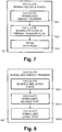
- shows a flow diagram illustrating an exemplary sequence of steps for calculating normalized data points from measurement data.
- Figure 8:
- shows a flow diagram illustrating an exemplary sequence of steps for calculating a normalized energy transfer.
- Figure 9:
- shows a flow diagram illustrating an exemplary sequence of steps for detecting deviations from expected energy transfer using a characteristic energy transfer curve.
- Figure 10:
- shows a graph illustrating the sensible and latent parts of the total energy transfer.
- Figure 11:
- shows an upper graph illustrating a plurality of non-normalized data points indicating total energy transfer per flow of thermal transfer fluid based on measurement data, and a lower graph illustrating a plurality of data points indicating normalized total energy transfer per normalized flow of thermal transfer fluid.
- Figure 12:
- shows an upper graph illustrating a plurality of non-normalized data points indicating the sensible part of the energy transfer per flow of thermal transfer fluid based on measurement data, and a lower graph illustrating a plurality of data points indicating a normalized sensible part per normalized flow of thermal transfer fluid.
- Figure 13:
- shows an upper graph illustrating a plurality of non-normalized data points indicating the latent part of the energy transfer per flow of thermal transfer fluid based on measurement data, and a lower graph illustrating a plurality of data points indicating a normalized latent part per normalized flow of thermal transfer fluid.
- In
Figures 1-4 ,reference numeral 10 refers to an HVAC system (Heating, Ventilation, Air Conditioning, and Cooling). As illustrated inFigure 1 , theHVAC system 10 comprises athermal energy exchanger 1, e.g. a heat exchanger for heating or a cooling device for cooling. As further illustrated inFigure 1 , theHVAC system 10 comprises anair transport system 3 for moving air through thethermal energy exchanger 1 and a thermal transferfluid transport system 2 for moving thermal transfer fluid, e.g. water or a refrigerant, through thethermal energy exchanger 1. As indicated schematically inFigure 1 , theair transport system 3 comprises various airside system components 30 andair ducts 300 for conducting an air flow through thethermal energy exchanger 1. The airside system components 30 comprise a ventilator, a controller, and an optionalair flow sensor 33 for conducting and controlling the flow of air through thethermal energy exchanger 1 and ultimately through or into a room or building. As further indicated schematically inFigure 1 , the thermal transferfluid transport system 2 comprises various fluidside system components 20 andfluid conduits 200 for conducting a flow of thermal transfer fluid through thethermal energy exchanger 1. The fluidside system components 20 comprise amotorized valve 21, acontroller 22, anoptional flow sensor 23, and further components, such as a pump, for conducting and controlling the flow of thermal transfer fluid through thethermal energy exchanger 1. - As illustrated schematically in
Figure 1 , theHVAC system 10 further comprises an air sideinlet sensor system 11, an air sideoutlet sensor system 12, a fluid sideinlet sensor system 13, and a fluid sideoutlet sensor system 14. The air sideinlet sensor system 11 comprises an enthalpy sensor or a combination of temperature and humidity sensors configured to measure the enthalpy of the air entering thethermal energy exchanger 1. The air sideoutlet sensor system 12 comprises an enthalpy sensor or a combination of temperature and humidity sensors configured to measure or determine the enthalpy of the air exiting thethermal energy exchanger 1, respectively. The fluid sideinlet sensor system 13 comprises a temperature sensor to determine the temperature or enthalpy of the thermal transfer fluid entering thethermal energy exchanger 1. The fluid sideoutlet sensor system 14 comprises a temperature sensor to determine the temperature or enthalpy of the thermal transfer fluid exiting thethermal energy exchanger 1. Thesensor systems computer system 4 and/or the controller(s) 22. - As illustrated in
Figures 1-4 , theHVAC system 10 comprises or is at least connected via acommunication network 5 to acomputer system 4. Depending on the embodiment, thecomputer system 4 comprises one or more operational computers with one or more programmable processors and a data storage system connected to the processor(s). As indicated schematically inFigures 1 and4 byreference numeral 40, thecomputer system 4 and thecontroller 22 constitute a control system, particularly a computerized HVAC control system. In the embodiment ofFigure 2 , theHVAC system 10 and one or more of itscontrollers 22 are connected viacommunication network 5 to aremote computer system 4, e.g. a cloud-based computer system connected to theHVAC system 10 vie the Internet. In the embodiment ofFigure 3 , thecomputer system 4 is a part of theHVAC system 10 and is connected via acommunication network 5, such as a LAN (Local Area Network) or WLAN (Wireless Local Area Network), to one ormore controllers 22 of theHVAC system 10. In the embodiment ofFigure 4 , thecomputer system 4 is a part of theHVAC system 10 and thecontroller 22 is part of thecomputer system 4 or thecontroller 22 constitutes thecomputer system 4, respectively. Thecontroller 22 includes an electronic circuit, e.g. a programmable processor, an application specific integrated circuit (ASIC), or another logic unit. Thecontroller 22 further comprise a communication module configured for wireless and/or wired data communication with thecomputer system 4, thesensor systems optional flow sensors valve 21 or its actuator, respectively, to control the flow of thermal transfer fluid. Thecontroller 22 and thecomputer system 4 are configured (programmed) to perform various functions described later in more detail. Depending on the embodiment thecommunication network 5 includes fixed communication networks or busses and/or mobile communication networks, e.g. WLAN, GSM (Global System for Mobile Communications), UMTS (Universal Mobile Telephone System), or other mobile radio networks. - In the following paragraphs, described with reference to
Figures 5-9 are possible sequences of steps performed by thecontrol system 40, thecomputer system 4, and/orcontroller 22, respectively, for operating thethermal energy exchanger 1. - As illustrated in
Figures 5 and 6 , in step S1, thecontrol system 40, i.e. thecomputer system 4 or thecontroller 22, respectively, records measurement data sets obtained from the sensor systems 11-14 and the optional airside flow sensor 33 and fluidside flow sensor 23. Specifically, the measurement data sets include for a particular point in time data values for calculating a normalized energy transfer, representing the thermal energy transferred in thethermal energy exchanger 1, from the thermal transfer fluid to the air, normalized by one or more normalization variables as will be described later in more detail. - In step S2, the
computer system 4 calculates normalized data points from the measurement data sets using normalization variables which are either data values included in the measurement data sets or fixed parameter values. Normalization is the process of reducing data redundancy and increasing independency. In the present context, the normalization reduces the measurement data to a single function or curve through mathematical transformation of the data. For example, the flow of thermal transfer fluid Φ W can be normalized using the flow of air Φ A , with or without using exponents α, β:

Figure 7 , in step S21, thecomputer system 4 calculates for the normalized data points a normalized total energy transfer. - The total energy or power transfer Q in the
thermal energy exchanger 1 from the thermal transfer fluid to the air is defined as:
- Q = Qtotal
- Total transferred energy or power
- ΦA
- Flow of air, airflow rate
- ΦW
- Flow of thermal transfer fluid, flow rate of thermal transfer fluid
- ΔHW = |HWi- HWo|
- Fluid (thermal transfer fluid) side enthalpy difference
- HWi
- Fluid (thermal transfer fluid) inlet enthalpy
- HWo
- Fluid (thermal transfer fluid) outlet enthalpy
- ΔHA = |HAi - HAo|
- Air side enthalpy difference
- HAi
- Air inlet enthalpy
- HAo
- Air outlet enthalpy
- If the air
side sensor systems - cpAir
- Heat capacity of air
- TAi
- Air inlet temperature
- TAo
- Air outlet temperature
- WAi
- Air inlet humidity
- WAo
- Air outlet humidity
- Depending on the embodiment or configuration, the data values for the measurement data sets are read from the sensors by the
computer system 4 or thecontroller 22, or reported by the sensors to thecomputer system 4 or thecontroller 22. Alternatively, the data values are collected by thecontroller 22 and later reported to thecomputer system 4. Any measurement data set recorded by thecomputer system 4 defines a non-normalized data point that includes data values for a particular point in time. - The normalized total energy transfer is calculated using the log mean enthalpy difference LMED and/or the air flow Φ A :


- In an alternative approach, normalized total energy transfer is calculated using the log mean enthalpy difference LMED and/or the flow of thermal transfer fluid Φ W :

- In step S22, the
computer system 4 calculates a normalized flow of the thermal transfer fluid:
- In a configuration or scenario without
air flow sensor 33 and/orfluid flow sensor 23, the normalized flow of thermal transfer fluid per air flow

- Furthermore, the normalized total energy transfer


- Correspondingly, for the alternative approach where the normalized total energy transfer is calculated using the flow of thermal transfer fluid Φ W , the normalized total energy transfer


- In step S23, the
computer system 4 stores the normalized data point that is defined by the normalized total energy transfer


-
Figure 11 illustrates in the upper graph an example of a plurality of measurement data sets, including (non-normalized) data points P with data values of total energy transfer Q per (non-normalized) flow of thermal transfer fluid Φ W .Figure 11 illustrates in the lower graph for said example of measurement data sets the normalized data points Pn defined by the normalized total energy transfer per normalized flow of the thermal transfer fluid

-
Figure 10 illustrates for an example of the total energy transfer Q the part of the latent energy Qlatent and the part of the sensible energy Qsensible dependent on the flow of thermal transfer fluid Φ W . - In the embodiment of
Figure 8 , in step S211, thecomputer system 4 calculates the sensible Qsensible and the latent part Qlatent of the total energy transfer Q. Specifically, thecomputer system 4 uses the sensible heat ratio (SHR) for calculating the sensible Qsensible and the latent Q latent parts:


- In
step S21 2, thecomputer system 4 calculates for the sensible part Qsensible a normalized sensible part. Specifically, thecomputer system 4 calculates the normalized sensible part using the difference of the temperature T Win of the thermal transfer fluid entering thethermal energy exchanger 1 and the temperature TAin of the air entering the thermal energy exchanger 1:
- In step S213, the
computer system 4 calculates for the latent part Qlatent a normalized latent part. Specifically, thecomputer system 4 calculates the normalized latent part, using the dew point temperature Tdewpt of the air and inlet temperature of the thermal transfer fluid TWi :
- Alternatively, the normalized latent part is calculated, using the difference of the absolute humidity value Wabs of the air entering the
thermal energy exchanger 1 and an absolute humidity value at saturation Wsat (TWi ) at the temperature TWi of the thermal transfer fluid entering the thermal energy exchanger 1:
-
Figure 12 illustrates in the upper graph an example of a plurality non-normalized data points S with data values of sensible energy transfer Qsensible per (non-normalized) flow of thermal transfer fluid Φ W .Figure 12 illustrates in the lower graph for said example of data points S the normalized data points Sn defined by the normalized sensible energy transfer

-
Figure 13 illustrates in the upper graph an example of a plurality non-normalized data points L with data values of latent energy transfer Qlatent per (non-normalized) flow of thermal transfer fluid Φ W .Figure 13 illustrates in the lower graph for said example of data points L the normalized data points Ln defined by the normalized latent energy transfer


- It should be noted here that, as one skilled in the art will understand, graphs corresponding to those of
Figures 11 ,12 , and13 can be generated for scenarios where, without the use of flow sensors, the normalized total energy transfer is calculated entirely from enthalpy values and represented on the y-axis by normalized enthalpy values


- Reverting to
Figures 5 and 6 , in step S3, thecomputer system 4 determines a characteristic transfer curve for thethermal energy exchanger 1. Specifically, thecomputer system 4 determines the characteristic transfer curve for thethermal energy exchanger 1 using the normalized data points Pn, Sn, Ln calculated and recorded for thethermal energy exchanger 1 over an extended period of time, e.g. during a calibration or commissioning phase, of one or more days, or even several weeks or months, as a best fit for the plurality of normalized data points Pn, Sn, Ln. In the lower graph ofFigure 11 the fitted characteristic transfer curve cP is indicated as a white curve running through the normalized data points Pn for normalized total energy transfer. In the lower graph ofFigure 12 the fitted characteristic transfer curve cS is indicated as a white curve running through the normalized data points Sn for normalized sensible energy transfer. In the lower graph ofFigure 13 the fitted characteristic transfer curve cL is indicated as a white curve running through the normalized data points Ln for normalized sensible energy transfer. - As illustrated in the embodiment of
Figure 6 , in optional step S4, thecomputer system 4 determines an efficiency boundary. Specifically, thecomputer system 4 determines the efficiency boundary bP, bS, bL (seeFigures 11 ,12 , and13 ) for thethermal energy exchanger 1 using the characteristic transfer curves cP, cS, cL or the normalized data points Pn, Sn, Ln. More specifically, thecomputer system 4 determines on the characteristic transfer curves cP, cS, cL boundary points BP, BS, BL (seeFigures 11 ,12 , and13 ) where the increase of the thermal energy transfer for an increase of the flow of thermal transfer fluid falls below a defined threshold value. The boundary bP, bS, bL is defined from the boundary points BP, BS, BL of several characteristic transfer curves cP, cS, cL determined for different sets of normalized data points, normalize separately for the total energy transfer, the latent energy transfer, and the sensible energy transfer, and/or for different values of the normalization variable(s) used, e.g. the log mean enthalpy difference, the air flow Φ A , the flow of thermal transfer fluid Φ W , the temperature TWi of the thermal transfer fluid entering thethermal energy exchanger 1, the temperature TAi of the air entering thethermal energy exchanger 1, the dew point temperature Tdewpt of the air, the absolute humidity value Wabs of the air entering thethermal energy exchanger 1, and/or the absolute humidity value at saturation Wsat (TWi ) at the temperature T Wi of the thermal transfer fluid entering thethermal energy exchanger 1. - In step S5, the
controller 22 controls operation of thethermal energy exchanger 1 using the efficiency boundary bP, bS, bL and/or the characteristic energy transfer curve cP, cS, cL. Specifically, thecontroller 22 controls operation of thethermal energy exchanger 1 by controlling operating parameters of thethermal energy exchanger 1. The operating parameters of thethermal energy exchanger 1 include the flow of the thermal transfer fluid Φ W , the air flow Φ A , and/or the temperature TWin of the thermal transfer fluid entering thethermal energy exchanger 1. In a first aspect, thecontroller 22 controls the operating parameters such as to maintain a normalized performance of thethermal energy exchanger 1, whereby thecontroller 22 keeps thethermal energy exchanger 1 operating on the (applicable) characteristic energy transfer curve cP, cS, cL. Detection of deviations from the characteristic energy transfer curve cP, cS, cL will be described later with reference toFigure 9 . In a second aspect, thecontroller 22 further controls the operating parameters such as to optimize performance of thethermal energy exchanger 1, whereby thecontroller 22 keeps thethermal energy exchanger 1 operating within an efficient area aP, aS, aL defined by the efficiency boundary bP, bS, bL. Within the efficient area aP, aS, aL, on the characteristic energy transfer curve cP, cS, cL, the thermal energy transfer increases comparably more with an increasing flow of thermal transfer fluid, than with an increasing flow of thermal transfer on the characteristic energy transfer curve outside the efficient area aP, aS, aL. One skilled in the art will understand that efficiency boundaries and/or efficient areas can be determined correspondingly and apply accordingly to scenarios where, without the use of flow sensors, the normalized total energy transfer is calculated entirely from enthalpy values and represented by


controller 22 is set to control the operating parameters to maintain normalized performance according to the first aspect and/or to optimize performance according to the second aspect. For embodiments or configurations where thecomputer system 4 is arranged separately or remotely from thecontroller 22, the efficiency boundary bP, bS, bL is transferred from thecomputer system 4 to thecontroller 22. Furthermore, one skilled in the art that will understand that in different embodiments, for maintaining normalized performance according to the first aspect and/or for optimizing performance according to the second aspect, thecomputer system 4 or thecontroller 22, respectively, generates control signals for controlling the operating parameters. The control signals are transmitted from thecomputer system 4 or thecontroller 22, respectively, to a building control system, avalve 21, a damper, a pump, a fan, and/or related actuators, for example. - As illustrated in
Figure 9 , in step S61, thecomputer system 4 determines the characteristic energy transfer curve cP, cS, cL that defines the expected energy transfer, i.e. the characteristic energy transfer curve cP, cS, cL that applies to the present operating conditions of thethermal energy exchanger 1, e.g. the current flow of air Φ A , the current flow of thermal transfer fluid Φ W , or the current inlet temperature of the thermal transfer fluid TWin . - In step S62, the
computer system 4 detects a deviation of the normalized energy transfer from the expected energy transfer by comparing one or more data points with the current or recent normalized energy transfer to the expected energy transfer defined by the characteristic energy transfer curve cP, cS, cL selected in step S61. - Upon detection of a deviation, in step S63, the
computer system 4 initiates exception processing. Depending on the scenario, embodiment, and/or configuration, thecomputer system 4 generates an alarm signal, an alarm message, selects an alternative characteristic energy transfer curve from a set of different characteristic energy transfer curves, and/or determines an alternative characteristic energy transfer curve using the plurality of measurement data sets. Specifically, for long term diagnostics, where for an ongoing period of time, e.g. several days, weeks, months, or even years, the normalized energy transfer continuously deviates from the expected energy transfer, thecomputer system 4 establishes that the current normalized data points or the related characteristic energy transfer curve deviate from the expected energy transfer, defined by an earlier characteristic energy transfer curve, e.g. determined during commissioning of thethermal energy exchanger 1, e.g. because of fauling of the coil of the thermal energy exchanger or other environmental influences. In addition to a long term diagnostic report, thecomputer system 4 generates a new, alternative characteristic energy transfer curve. For short or long term optimizations of exceptions or deviations, for example, if the normalized data point is detected to be within the efficient area aP, aS, aL, but below the characteristic energy transfer curve cP, cS, cL, thecontroller 22 controls the operating parameters such as to move the normalized data point onto the characteristic energy transfer curve cP, cS, cL. Thus, thecontroller 22 corrects and optimizes situations that arise from temporary disturbances or sub-optimal conditions or settings. In addition, if the normalized data point is detected to be within the efficient area aP, aS, aL, but above the characteristic energy transfer curve cP, cS, cL, thecontroller 22 generates an alarm or diagnostic report that indicates the detection of deviations that are caused, for example, because of sub-optimal or incorrect system setup configuration, such as arrangements of distant temperature sensors that cause excessive time lags or other settings that lead to instable system behaviours. - In further embodiments, the normalized total energy transfer is calculated using the temperatures TW
i , TWo of the thermal transfer fluid entering or exiting thethermal energy exchanger 1, respectively, and the temperatures TAi , TAo of the air entering or exiting thethermal energy exchanger 1, respectively, for example:
- As described above, the normalization variables used for calculating the normalized energy transfer include air side variables, such as the flow of air through the thermal energy exchanger Φ A , the temperature TA
i of the air entering thethermal energy exchanger 1, the temperature TAo of the air exiting thethermal energy exchanger 1, the dew point temperature Tdewpt of the air, the absolute humidity value WAi of the air entering thethermal energy exchanger 1, the absolute humidity value WAo of the air exiting thethermal energy exchanger 1, and the absolute humidity value at saturation Wsat (TWi ) at the temperature TWi of the thermal transfer fluid entering thethermal energy exchanger 1; the air inlet enthalpy value HAi , the air outlet enthalpy value HAo , the air side enthalpy difference ΔHA =|HAi -HAo |, as well as composite variables based on air side variables, such as the log mean enthalpy difference LMED; and variables on the thermal transfer fluid side, such as the flow of thermal transfer fluid Φ W , the temperature TWi of the thermal transfer fluid entering thethermal energy exchanger 1, and the temperature TWo of the thermal transfer fluid exiting thethermal energy exchanger 1. - It should be noted that, in the description, the sequence of the steps has been presented in a specific order, one skilled in the art will understand, however, that the order of at least some of the steps could be altered, without deviating from the scope of the invention.
Claims (25)
- A method of operating a thermal energy exchanger (1) for exchanging thermal energy between a thermal transfer fluid, flowing through the thermal energy exchanger (1) in a fluid conduit (200), and air, being conducted through the thermal energy exchanger (1) in an air duct (300), the method comprising:recording in a control system (40) a plurality of measurement data sets, each of the measurement data sets including for a different point in time data values defining a normalized energy transfer which represents the thermal energy transferred in the thermal energy exchanger (1), from the thermal transfer fluid to the air,normalized by one or more normalization variables including at least one air side variable; characterised by further comprising:the control system (40) calculating for each of the measurement data sets a normalized data point (Pn, Sn, Ln) defined by the normalized energy transfer; andthe control system (40) determining for the thermal energy exchanger (1) a characteristic energy transfer curve (cP, cS, cL) which fits the normalized data points (Pn, Sn, Ln); and
the control system (40) controlling operating parameters, wherein the operating parameters include the flow of thermal transfer fluid through the thermal energy exchanger, the flow of air through the thermal energy exchanger, and/or the temperature of the thermal transfer fluid entering the thermal energy exchanger. - The method of claim 1, further comprising the control system (40) determining a boundary (bP, bS, bL) for efficient thermal energy transfer in the thermal energy exchanger (1) between the thermal transfer fluid and the air, whereby the boundary (bP, bS, bL) defines an efficient area (aP, aS, aL), where on the characteristic energy transfer curve (cP, cS, cL) the thermal energy transfer is more energy efficient than on the characteristic energy transfer curve (cP, cS, cL) outside the efficient area (aP, aS, aL); and the control system (40) keeping the thermal energy exchanger (1) operating within said efficient area (aP, aS, aL).
- The method of one of claims 1 or 2, wherein the control system (40) controls operating parameters to maintain operation of the thermal energy exchanger (1) on the characteristic energy transfer curve (cP, cS, cL), the operating parameters comprising at least one of: flow of thermal transfer fluid through the thermal energy exchanger (1), flow of air through the thermal energy exchanger (1), and temperature of the thermal transfer fluid entering the thermal energy exchanger (1).
- The method of one of claims 1 to 3, wherein each of the measurement data sets includes an air inlet enthalpy value, an air outlet enthalpy value, a thermal transfer fluid inlet enthalpy value, and a thermal transfer fluid outlet enthalpy value; and the control system (40) calculates the normalized energy transfer for each of the normalized data points (Pn, Sn, Ln), using the air inlet enthalpy value, the air outlet enthalpy value, the thermal transfer fluid inlet enthalpy value, and the thermal transfer fluid outlet enthalpy value.
- The method of one of claims claim 1 to 3, wherein each of the measurement data sets includes a temperature value of the air entering the thermal energy exchanger (1), a temperature value of the air exiting the thermal energy exchanger (1), a humidity value of the air entering the thermal energy exchanger (1), a humidity value of the air exiting the thermal energy exchanger (1), a temperature value of the thermal transfer fluid entering the thermal energy exchanger (1), and a temperature value of the thermal transfer fluid exiting the thermal energy exchanger (1); and the control system (40) calculates the normalized energy transfer for each of the normalized data points (Pn, Sn, Ln), using the temperature value of the air entering the thermal energy exchanger (1), the temperature value of the air exiting the thermal energy exchanger (1), the humidity value of the air entering the thermal energy exchanger (1), the humidity value of the air exiting the thermal energy exchanger (1), the temperature value of the thermal transfer fluid entering the thermal energy exchanger (1), and the temperature value of the thermal transfer fluid exiting the thermal energy exchanger (1).
- The method of one of claims 1 to 5, wherein each of the measurement data sets includes for the different points in time the flow of thermal transfer fluid through the thermal energy exchanger (1) and the flow of air through the thermal energy exchanger (1); and the control system (40) calculates for each of the normalized data points (Pn, Sn, Ln) a normalized flow of thermal transfer fluid through the fluid conduit (200) normalized by the flow of air.
- The method of one of claims 1 to 6, wherein each of the measurement data sets includes data values defining a log mean enthalpy difference from an inlet enthalpy difference, of the air entering the thermal energy exchanger (1) and the thermal transfer fluid entering the thermal energy exchanger (1), and an outlet enthalpy difference, of the air exiting the thermal energy exchanger (1) and the thermal transfer fluid exiting the thermal energy exchanger (1); and the control system (40) calculates the normalized energy transfer for each of the normalized data points (Pn) using the log mean enthalpy difference.
- The method of one of claims 1 to 7, wherein each of the measurement data sets includes the flow of air through the thermal energy exchanger (1); and the control system (40) calculates the normalized energy transfer for each of the normalized data points (Pn) using the flow of air through the thermal energy exchanger (1).
- The method of one of claims 1 to 7, wherein each of the measurement data sets includes the flow of thermal transfer fluid through the thermal energy exchanger (1); and the control system (40) calculates the normalized energy transfer for each of the normalized data points (Pn) using the flow of thermal transfer fluid through the thermal energy exchanger (1).
- The method of one of claims 1 to 5, wherein each of the measurement data sets includes for the different points in time data values defining an air side enthalpy difference of the air entering the thermal energy exchanger (1) and the air exiting the thermal energy exchanger (1), and data values defining an enthalpy difference on the thermal transfer fluid side of the thermal transfer fluid entering the thermal energy exchanger (1) and the thermal transfer fluid exiting the thermal energy exchanger (1); and the control system (40) calculates for each of the normalized data points (Pn) a value representative of the normalized flow, from the air side enthalpy difference and the enthalpy difference on the thermal transfer fluid side.
- The method of claim 10, wherein each of the measurement data sets includes data values defining a log mean enthalpy difference from an inlet enthalpy difference, of the air entering the thermal energy exchanger (1) and the thermal transfer fluid entering the thermal energy exchanger (1), and an outlet enthalpy difference, of the air exiting the thermal energy exchanger (1) and the thermal transfer fluid exiting the thermal energy exchanger (1); and the control system (40) calculates the normalized energy transfer for each of the normalized data points (Pn) using the air side enthalpy difference and the log mean enthalpy difference.
- The method of claim 10, wherein each of the measurement data sets includes data values defining a log mean enthalpy difference from an inlet enthalpy difference, of the air entering the thermal energy exchanger (1) and the thermal transfer fluid entering the thermal energy exchanger (1), and an outlet enthalpy difference, of the air exiting the thermal energy exchanger and the thermal transfer fluid exiting the thermal energy exchanger; and the control system (40) calculates the normalized energy transfer for each of the normalized data points (Pn) using the enthalpy difference on the thermal transfer fluid side and the log mean enthalpy difference.
- The method of one of claims 2 to 5, wherein each of the measurement data sets includes data values for determining a sensible part and a latent part of the thermal energy transferred in the thermal energy exchanger (1), from the thermal transfer fluid to the air; the control system (40) calculates a normalized sensible part and a normalized latent part, using one or more normalization variables; and the control system (40) determines boundaries (bS, bL) for efficient thermal energy transfer in the thermal energy exchanger (1) between the thermal transfer fluid and the air separately for the normalized sensible part and the normalized latent part; and the control system (40) keeps the thermal energy exchanger operating within efficient areas (aS, aL) defined by said boundaries (bS, bL).
- The method of claim 13, wherein each of the measurement data sets includes a temperature value of the thermal transfer fluid entering the thermal energy exchanger (1), and a temperature value of the air entering the thermal energy exchanger (1); and the control system (40) calculates the normalized sensible part (Sn) of the thermal energy transferred in the thermal energy exchanger (1) using the difference of the temperature value of the thermal transfer fluid entering the thermal energy exchanger (1) and the temperature value of the air entering the thermal energy exchanger (1).
- The method of one of claims 13 or 14, wherein each of the measurement data sets includes a temperature value of the thermal transfer fluid entering the thermal energy exchanger (1); and the control system (40) calculates the normalized latent part (Ln) of the thermal energy transferred in the thermal energy exchanger (1) using the difference of the temperature value of a dew point temperature of the air and temperature the thermal transfer fluid entering the thermal energy exchanger (1).
- The method of one of claims 13 or 14, wherein each of the measurement data sets includes a temperature value of the thermal transfer fluid entering the thermal energy exchanger (1), an absolute humidity value of the air entering the thermal energy exchanger (1), and a temperature value of the thermal transfer fluid entering the thermal energy exchanger (1); and the control system (40) calculates the normalized latent part (Ln) of the thermal energy transferred in the thermal energy exchanger (1) using the difference of the absolute humidity value of the of the air entering the thermal energy exchanger (1) and an absolute humidity value at saturation at the temperature value of the thermal transfer fluid entering the thermal energy exchanger (1).
- The method of one of claims 1 to 16, further comprising the control system (40) determining a characteristic energy transfer curve (cP, cS, cL), which indicates an expected energy transfer in the thermal energy exchanger (1) from the thermal transfer fluid to the air; the control system (40) detecting a deviation of the normalized energy transfer (Pn, Sn, Ln) from the expected energy transfer; and, upon detection of a deviation, the control system (40) initiating exception processing.
- The method of claim 17, further comprising the control system (40) selecting a characteristic energy transfer curve (cP, cS, cL) from a set of different characteristic energy transfer curves (cP, cS, cL), which indicate for different air side parameters an expected energy transfer in the thermal energy exchanger (1) from the thermal transfer fluid to the air, using airside parameters included in the measurement data sets.
- The method of one of claims 17 or 18, further comprising the control system (40) including in the exception processing at least one of the following steps: generating an alarm signal, selecting an alternative characteristic energy transfer curve (cP, cS, cL) from a set of different characteristic energy transfer curves (cP, cS, cL), and determining an alternative characteristic energy transfer curve (cP, cS, cL) using the plurality of measurement data sets.
- A control system (40) for operating a thermal energy exchanger (1) for exchanging thermal energy between a thermal transfer fluid, flowing through the thermal energy exchanger (1) in a fluid conduit (200), and air, being conducted through the thermal energy exchanger (1) in an air duct (300), the control system (40) comprising at least one processor configured to:record in the control system (40) a plurality of measurement data sets, each of the measurement data sets including for a different point in time data values defining a normalized energy transfer which represents the thermal energy transferred in the thermal energy exchanger (1), from the thermal transfer fluid to the air, normalized by one or more normalization variables including at least one air side variable;calculate for each of the measurement data sets a normalized data point (Pn, Sn,Ln) defined by the normalized energy transfer; anddetermine for the thermal energy exchanger (1) a characteristic energy transfer curve (cP, cS, cL) which fits the normalized data points (Pn, Sn, Ln).
- The control system (40) of claim 20, wherein the processor is further configured to determine a boundary (bP, bS, bL) for efficient thermal energy transfer in the thermal energy exchanger (1) between the thermal transfer fluid and the air, whereby the boundary (bP, bS, bL) defines an efficient area (aP, aS, aL), where on the characteristic energy transfer curve (cP, cS, cL) the thermal energy transfer is more energy efficient than on the characteristic energy transfer curve (cP, cS, cL) outside the efficient area (aP, aS, aL); and keep the thermal energy exchanger (1) operating within said efficient area (aP, aS, aL).
- The control system (40) of one of claims 20 or 21, wherein the processor is further configured to perform steps of the method of one of claims 2 to 19.
- A computer program product comprising a non-transient computer-readable medium having stored thereon computer program code configured to control a processor of a control system (40) for operating a thermal energy exchanger (1) for exchanging thermal energy between a thermal transfer fluid, flowing through the thermal energy exchanger (1) in a fluid conduit (200), and air, being conducted through the thermal energy exchanger (1) in an air duct (300), such that the processor performs the following steps:recording in the control system (40) a plurality of measurement data sets, each of the measurement data sets including for a different point in time data values defining a normalized energy transfer which represents the thermal energy transferred in the thermal energy exchanger (1), from the thermal transfer fluid to the air, normalized by one or more normalization variables including at least one air side variable;calculating for each of the measurement data sets a normalized data point (Pn, Sn, Ln) defined by the normalized energy transfer; anddetermining for the thermal energy exchanger (1) a characteristic energy transfer curve (cP, cS, cL) which fits the normalized data points (Pn, Sn, Ln).
- The computer program product of claim 23, wherein the computer program code is further configured to control the processor such that the processor determines a boundary (bP, bS, bL) for efficient thermal energy transfer in the thermal energy exchanger (1) between the thermal transfer fluid and the air, whereby the boundary (bP, bS, bL) defines an efficient area (aP, aS, aL), where on the characteristic energy transfer curve (cP, cS, cL) the thermal energy transfer is more energy efficient than on the characteristic energy transfer curve (cP, cS, cL) outside the efficient area (aP, aS, aL); and keeps the thermal energy exchanger (1) operating within said efficient area (aP, aS, aL).
- The computer program product of one of claims 23 or 24, wherein the computer program code is further configured to control the processor such that the processor performs steps of the method of one of claims 2 to 19.
Applications Claiming Priority (2)
| Application Number | Priority Date | Filing Date | Title |
|---|---|---|---|
| CH12552015 | 2015-09-01 | ||
| PCT/EP2016/067657 WO2017036674A1 (en) | 2015-09-01 | 2016-07-25 | Method and system for operating a thermal energy exchanger |
Publications (2)
| Publication Number | Publication Date |
|---|---|
| EP3344925A1 EP3344925A1 (en) | 2018-07-11 |
| EP3344925B1 true EP3344925B1 (en) | 2021-05-26 |
Family
ID=54065139
Family Applications (1)
| Application Number | Title | Priority Date | Filing Date |
|---|---|---|---|
| EP16751208.6A Active EP3344925B1 (en) | 2015-09-01 | 2016-07-25 | Method and system for operating a thermal energy exchanger |
Country Status (4)
| Country | Link |
|---|---|
| US (1) | US10627129B2 (en) |
| EP (1) | EP3344925B1 (en) |
| CN (1) | CN108291734B (en) |
| WO (1) | WO2017036674A1 (en) |
Cited By (1)
| Publication number | Priority date | Publication date | Assignee | Title |
|---|---|---|---|---|
| EP4411266A1 (en) | 2023-02-01 | 2024-08-07 | Siemens Schweiz AG | Weighted return temperature limitation |
Families Citing this family (5)
| Publication number | Priority date | Publication date | Assignee | Title |
|---|---|---|---|---|
| US10746428B2 (en) | 2017-03-09 | 2020-08-18 | Johnson Controls Technology Company | Building automation system with a dynamic cloud based control framework |
| EP3489591B1 (en) | 2017-11-24 | 2021-09-01 | Siemens Schweiz AG | Smart thermal energy exchanger |
| US12072116B2 (en) * | 2018-06-12 | 2024-08-27 | Belimo Holding Ag | Method and system for controlling energy transfer of a thermal energy exchanger |
| CN115667804A (en) * | 2020-01-24 | 2023-01-31 | 贝利莫控股公司 | Method and system for monitoring energy flow of an HVAC system |
| CN115133076A (en) * | 2022-07-12 | 2022-09-30 | 同济大学 | On-line self-adaptive anti-surge control method for fuel cell air circuit |
Family Cites Families (12)
| Publication number | Priority date | Publication date | Assignee | Title |
|---|---|---|---|---|
| ES2561829T3 (en) * | 2002-10-15 | 2016-03-01 | Danfoss A/S | A procedure to detect a heat exchanger anomaly |
| JP2006010322A (en) * | 2004-06-22 | 2006-01-12 | Yokogawa Electric Corp | Thermal flowmeter |
| DK2641027T3 (en) * | 2010-11-17 | 2018-03-05 | Belimo Holding Ag | Device and method for controlling the opening of a valve in a heating, ventilation and air conditioning system (VVLK system) |
| CN102135021B (en) * | 2011-02-25 | 2013-12-25 | 华东理工大学 | Method for predicting shaft power of industrial extraction condensing steam turbine |
| RU113837U1 (en) * | 2011-07-13 | 2012-02-27 | Сергей Сергеевич Сергеев | DEVICE FOR DETERMINING THE EFFICIENCY OF HEATING SUPPLY OF BUILDING |
| CH705466A1 (en) * | 2011-09-05 | 2013-03-15 | Belimo Holding Ag | Process for operating and / or monitoring an HVAC system and HVAC system for carrying out the process. |
| CN102705957B (en) * | 2012-06-07 | 2014-06-11 | 华南理工大学 | Method and system for predicting hourly cooling load of central air-conditioner in office building on line |
| US8496234B1 (en) * | 2012-07-16 | 2013-07-30 | Massachusetts Institute Of Technology | Thermodynamic balancing of combined heat and mass exchange devices |
| CN105378575B (en) * | 2013-05-16 | 2018-09-07 | 贝利莫控股公司 | Device and method for the aperture for controlling the valve in HVAC system |
| US20150060557A1 (en) * | 2013-08-30 | 2015-03-05 | LH Thermostat Systems LLC | Energy saving apparatus, system and method |
| FR3011624B1 (en) * | 2013-10-09 | 2017-12-22 | Commissariat Energie Atomique | SYSTEM AND METHOD FOR PROCESSING AND CONDITIONING AIR |
| EP2896899B1 (en) * | 2013-12-20 | 2017-05-24 | Belimo Holding AG | Valve control in an HVAC system with sensors |
-
2016
- 2016-07-25 US US15/744,178 patent/US10627129B2/en active Active
- 2016-07-25 EP EP16751208.6A patent/EP3344925B1/en active Active
- 2016-07-25 WO PCT/EP2016/067657 patent/WO2017036674A1/en active Application Filing
- 2016-07-25 CN CN201680050352.5A patent/CN108291734B/en active Active
Non-Patent Citations (1)
| Title |
|---|
| None * |
Cited By (1)
| Publication number | Priority date | Publication date | Assignee | Title |
|---|---|---|---|---|
| EP4411266A1 (en) | 2023-02-01 | 2024-08-07 | Siemens Schweiz AG | Weighted return temperature limitation |
Also Published As
| Publication number | Publication date |
|---|---|
| CN108291734A (en) | 2018-07-17 |
| WO2017036674A1 (en) | 2017-03-09 |
| US10627129B2 (en) | 2020-04-21 |
| US20180195753A1 (en) | 2018-07-12 |
| CN108291734B (en) | 2020-08-18 |
| EP3344925A1 (en) | 2018-07-11 |
Similar Documents
| Publication | Publication Date | Title |
|---|---|---|
| EP3344925B1 (en) | Method and system for operating a thermal energy exchanger | |
| EP2997430B1 (en) | Device and method for controlling the opening of a valve in an hvac system | |
| JP5629189B2 (en) | Control apparatus and method | |
| WO2016035121A1 (en) | Air conditioning system control device and air conditioning system control method | |
| CN108644968B (en) | Control method for air conditioning system | |
| US20160161139A1 (en) | State-based control in an air handling unit | |
| EP3306216B1 (en) | Control device for heat-pump-using system, and heat-pump-using system provided with same | |
| CN111213013B (en) | Method and system for controlling a valve in an HVAC system | |
| US9885489B2 (en) | HVAC systems | |
| EP3475623B1 (en) | Method and devices for controlling a fluid transportation network | |
| CN108592353B (en) | Control method for air conditioning system | |
| CN108826599B (en) | Control method for air conditioning system | |
| WO2022029127A1 (en) | Device and method for controlling an orifice of a valve in an hvac system | |
| US10739031B2 (en) | System and method using mobile device for automatic control on heating, ventilation and air conditioning | |
| US11199336B2 (en) | HVAC system with on-off control | |
| EP3098529B1 (en) | Coordinated control of hvac system using aggregated system demand | |
| WO2019238631A1 (en) | Method and system for controlling energy transfer of a thermal energy exchanger | |
| US20180364658A1 (en) | Adaptive control of hvac system | |
| JP2020098055A (en) | Air conditioning device and program | |
| US20200340701A1 (en) | System and method for building climate control |
Legal Events
| Date | Code | Title | Description |
|---|---|---|---|
| STAA | Information on the status of an ep patent application or granted ep patent |
Free format text: STATUS: THE INTERNATIONAL PUBLICATION HAS BEEN MADE |
|
| PUAI | Public reference made under article 153(3) epc to a published international application that has entered the european phase |
Free format text: ORIGINAL CODE: 0009012 |
|
| STAA | Information on the status of an ep patent application or granted ep patent |
Free format text: STATUS: REQUEST FOR EXAMINATION WAS MADE |
|
| 17P | Request for examination filed |
Effective date: 20180313 |
|
| AK | Designated contracting states |
Kind code of ref document: A1 Designated state(s): AL AT BE BG CH CY CZ DE DK EE ES FI FR GB GR HR HU IE IS IT LI LT LU LV MC MK MT NL NO PL PT RO RS SE SI SK SM TR |
|
| AX | Request for extension of the european patent |
Extension state: BA ME |
|
| DAV | Request for validation of the european patent (deleted) | ||
| DAX | Request for extension of the european patent (deleted) | ||
| GRAP | Despatch of communication of intention to grant a patent |
Free format text: ORIGINAL CODE: EPIDOSNIGR1 |
|
| STAA | Information on the status of an ep patent application or granted ep patent |
Free format text: STATUS: GRANT OF PATENT IS INTENDED |
|
| INTG | Intention to grant announced |
Effective date: 20201217 |
|
| GRAS | Grant fee paid |
Free format text: ORIGINAL CODE: EPIDOSNIGR3 |
|
| GRAA | (expected) grant |
Free format text: ORIGINAL CODE: 0009210 |
|
| STAA | Information on the status of an ep patent application or granted ep patent |
Free format text: STATUS: THE PATENT HAS BEEN GRANTED |
|
| AK | Designated contracting states |
Kind code of ref document: B1 Designated state(s): AL AT BE BG CH CY CZ DE DK EE ES FI FR GB GR HR HU IE IS IT LI LT LU LV MC MK MT NL NO PL PT RO RS SE SI SK SM TR |
|
| REG | Reference to a national code |
Ref country code: GB Ref legal event code: FG4D |
|
| REG | Reference to a national code |
Ref country code: CH Ref legal event code: EP |
|
| REG | Reference to a national code |
Ref country code: DE Ref legal event code: R096 Ref document number: 602016058412 Country of ref document: DE |
|
| REG | Reference to a national code |
Ref country code: AT Ref legal event code: REF Ref document number: 1396613 Country of ref document: AT Kind code of ref document: T Effective date: 20210615 |
|
| REG | Reference to a national code |
Ref country code: IE Ref legal event code: FG4D |
|
| REG | Reference to a national code |
Ref country code: LT Ref legal event code: MG9D |
|
| REG | Reference to a national code |
Ref country code: AT Ref legal event code: MK05 Ref document number: 1396613 Country of ref document: AT Kind code of ref document: T Effective date: 20210526 |
|
| PG25 | Lapsed in a contracting state [announced via postgrant information from national office to epo] |
Ref country code: LT Free format text: LAPSE BECAUSE OF FAILURE TO SUBMIT A TRANSLATION OF THE DESCRIPTION OR TO PAY THE FEE WITHIN THE PRESCRIBED TIME-LIMIT Effective date: 20210526 Ref country code: FI Free format text: LAPSE BECAUSE OF FAILURE TO SUBMIT A TRANSLATION OF THE DESCRIPTION OR TO PAY THE FEE WITHIN THE PRESCRIBED TIME-LIMIT Effective date: 20210526 Ref country code: HR Free format text: LAPSE BECAUSE OF FAILURE TO SUBMIT A TRANSLATION OF THE DESCRIPTION OR TO PAY THE FEE WITHIN THE PRESCRIBED TIME-LIMIT Effective date: 20210526 Ref country code: AT Free format text: LAPSE BECAUSE OF FAILURE TO SUBMIT A TRANSLATION OF THE DESCRIPTION OR TO PAY THE FEE WITHIN THE PRESCRIBED TIME-LIMIT Effective date: 20210526 Ref country code: BG Free format text: LAPSE BECAUSE OF FAILURE TO SUBMIT A TRANSLATION OF THE DESCRIPTION OR TO PAY THE FEE WITHIN THE PRESCRIBED TIME-LIMIT Effective date: 20210826 |
|
| REG | Reference to a national code |
Ref country code: NL Ref legal event code: MP Effective date: 20210526 |
|
| PG25 | Lapsed in a contracting state [announced via postgrant information from national office to epo] |
Ref country code: GR Free format text: LAPSE BECAUSE OF FAILURE TO SUBMIT A TRANSLATION OF THE DESCRIPTION OR TO PAY THE FEE WITHIN THE PRESCRIBED TIME-LIMIT Effective date: 20210827 Ref country code: LV Free format text: LAPSE BECAUSE OF FAILURE TO SUBMIT A TRANSLATION OF THE DESCRIPTION OR TO PAY THE FEE WITHIN THE PRESCRIBED TIME-LIMIT Effective date: 20210526 Ref country code: IS Free format text: LAPSE BECAUSE OF FAILURE TO SUBMIT A TRANSLATION OF THE DESCRIPTION OR TO PAY THE FEE WITHIN THE PRESCRIBED TIME-LIMIT Effective date: 20210926 Ref country code: PT Free format text: LAPSE BECAUSE OF FAILURE TO SUBMIT A TRANSLATION OF THE DESCRIPTION OR TO PAY THE FEE WITHIN THE PRESCRIBED TIME-LIMIT Effective date: 20210927 Ref country code: NO Free format text: LAPSE BECAUSE OF FAILURE TO SUBMIT A TRANSLATION OF THE DESCRIPTION OR TO PAY THE FEE WITHIN THE PRESCRIBED TIME-LIMIT Effective date: 20210826 Ref country code: PL Free format text: LAPSE BECAUSE OF FAILURE TO SUBMIT A TRANSLATION OF THE DESCRIPTION OR TO PAY THE FEE WITHIN THE PRESCRIBED TIME-LIMIT Effective date: 20210526 Ref country code: RS Free format text: LAPSE BECAUSE OF FAILURE TO SUBMIT A TRANSLATION OF THE DESCRIPTION OR TO PAY THE FEE WITHIN THE PRESCRIBED TIME-LIMIT Effective date: 20210526 Ref country code: SE Free format text: LAPSE BECAUSE OF FAILURE TO SUBMIT A TRANSLATION OF THE DESCRIPTION OR TO PAY THE FEE WITHIN THE PRESCRIBED TIME-LIMIT Effective date: 20210526 |
|
| PG25 | Lapsed in a contracting state [announced via postgrant information from national office to epo] |
Ref country code: NL Free format text: LAPSE BECAUSE OF FAILURE TO SUBMIT A TRANSLATION OF THE DESCRIPTION OR TO PAY THE FEE WITHIN THE PRESCRIBED TIME-LIMIT Effective date: 20210526 |
|
| PG25 | Lapsed in a contracting state [announced via postgrant information from national office to epo] |
Ref country code: SM Free format text: LAPSE BECAUSE OF FAILURE TO SUBMIT A TRANSLATION OF THE DESCRIPTION OR TO PAY THE FEE WITHIN THE PRESCRIBED TIME-LIMIT Effective date: 20210526 Ref country code: SK Free format text: LAPSE BECAUSE OF FAILURE TO SUBMIT A TRANSLATION OF THE DESCRIPTION OR TO PAY THE FEE WITHIN THE PRESCRIBED TIME-LIMIT Effective date: 20210526 Ref country code: CZ Free format text: LAPSE BECAUSE OF FAILURE TO SUBMIT A TRANSLATION OF THE DESCRIPTION OR TO PAY THE FEE WITHIN THE PRESCRIBED TIME-LIMIT Effective date: 20210526 Ref country code: EE Free format text: LAPSE BECAUSE OF FAILURE TO SUBMIT A TRANSLATION OF THE DESCRIPTION OR TO PAY THE FEE WITHIN THE PRESCRIBED TIME-LIMIT Effective date: 20210526 Ref country code: DK Free format text: LAPSE BECAUSE OF FAILURE TO SUBMIT A TRANSLATION OF THE DESCRIPTION OR TO PAY THE FEE WITHIN THE PRESCRIBED TIME-LIMIT Effective date: 20210526 Ref country code: RO Free format text: LAPSE BECAUSE OF FAILURE TO SUBMIT A TRANSLATION OF THE DESCRIPTION OR TO PAY THE FEE WITHIN THE PRESCRIBED TIME-LIMIT Effective date: 20210526 Ref country code: ES Free format text: LAPSE BECAUSE OF FAILURE TO SUBMIT A TRANSLATION OF THE DESCRIPTION OR TO PAY THE FEE WITHIN THE PRESCRIBED TIME-LIMIT Effective date: 20210526 |
|
| REG | Reference to a national code |
Ref country code: DE Ref legal event code: R097 Ref document number: 602016058412 Country of ref document: DE |
|
| PLBE | No opposition filed within time limit |
Free format text: ORIGINAL CODE: 0009261 |
|
| STAA | Information on the status of an ep patent application or granted ep patent |
Free format text: STATUS: NO OPPOSITION FILED WITHIN TIME LIMIT |
|
| PG25 | Lapsed in a contracting state [announced via postgrant information from national office to epo] |
Ref country code: MC Free format text: LAPSE BECAUSE OF FAILURE TO SUBMIT A TRANSLATION OF THE DESCRIPTION OR TO PAY THE FEE WITHIN THE PRESCRIBED TIME-LIMIT Effective date: 20210526 |
|
| REG | Reference to a national code |
Ref country code: BE Ref legal event code: MM Effective date: 20210731 |
|
| GBPC | Gb: european patent ceased through non-payment of renewal fee |
Effective date: 20210826 |
|
| 26N | No opposition filed |
Effective date: 20220301 |
|
| PG25 | Lapsed in a contracting state [announced via postgrant information from national office to epo] |
Ref country code: IS Free format text: LAPSE BECAUSE OF FAILURE TO SUBMIT A TRANSLATION OF THE DESCRIPTION OR TO PAY THE FEE WITHIN THE PRESCRIBED TIME-LIMIT Effective date: 20210926 Ref country code: LU Free format text: LAPSE BECAUSE OF NON-PAYMENT OF DUE FEES Effective date: 20210725 Ref country code: AL Free format text: LAPSE BECAUSE OF FAILURE TO SUBMIT A TRANSLATION OF THE DESCRIPTION OR TO PAY THE FEE WITHIN THE PRESCRIBED TIME-LIMIT Effective date: 20210526 |
|
| PG25 | Lapsed in a contracting state [announced via postgrant information from national office to epo] |
Ref country code: IE Free format text: LAPSE BECAUSE OF NON-PAYMENT OF DUE FEES Effective date: 20210725 Ref country code: GB Free format text: LAPSE BECAUSE OF NON-PAYMENT OF DUE FEES Effective date: 20210826 Ref country code: BE Free format text: LAPSE BECAUSE OF NON-PAYMENT OF DUE FEES Effective date: 20210731 |
|
| PG25 | Lapsed in a contracting state [announced via postgrant information from national office to epo] |
Ref country code: HU Free format text: LAPSE BECAUSE OF FAILURE TO SUBMIT A TRANSLATION OF THE DESCRIPTION OR TO PAY THE FEE WITHIN THE PRESCRIBED TIME-LIMIT; INVALID AB INITIO Effective date: 20160725 |
|
| PG25 | Lapsed in a contracting state [announced via postgrant information from national office to epo] |
Ref country code: CY Free format text: LAPSE BECAUSE OF FAILURE TO SUBMIT A TRANSLATION OF THE DESCRIPTION OR TO PAY THE FEE WITHIN THE PRESCRIBED TIME-LIMIT Effective date: 20210526 |
|
| PGFP | Annual fee paid to national office [announced via postgrant information from national office to epo] |
Ref country code: IT Payment date: 20230731 Year of fee payment: 8 Ref country code: CH Payment date: 20230801 Year of fee payment: 8 |
|
| PGFP | Annual fee paid to national office [announced via postgrant information from national office to epo] |
Ref country code: FR Payment date: 20230724 Year of fee payment: 8 |
|
| PG25 | Lapsed in a contracting state [announced via postgrant information from national office to epo] |
Ref country code: MK Free format text: LAPSE BECAUSE OF FAILURE TO SUBMIT A TRANSLATION OF THE DESCRIPTION OR TO PAY THE FEE WITHIN THE PRESCRIBED TIME-LIMIT Effective date: 20210526 |
|
| REG | Reference to a national code |
Ref country code: DE Ref legal event code: R084 Ref document number: 602016058412 Country of ref document: DE |
|
| PG25 | Lapsed in a contracting state [announced via postgrant information from national office to epo] |
Ref country code: MT Free format text: LAPSE BECAUSE OF FAILURE TO SUBMIT A TRANSLATION OF THE DESCRIPTION OR TO PAY THE FEE WITHIN THE PRESCRIBED TIME-LIMIT Effective date: 20210526 |
|
| PGFP | Annual fee paid to national office [announced via postgrant information from national office to epo] |
Ref country code: DE Payment date: 20240719 Year of fee payment: 9 |