EP3098529B1 - Coordinated control of hvac system using aggregated system demand - Google Patents
Coordinated control of hvac system using aggregated system demand Download PDFInfo
- Publication number
- EP3098529B1 EP3098529B1 EP16171315.1A EP16171315A EP3098529B1 EP 3098529 B1 EP3098529 B1 EP 3098529B1 EP 16171315 A EP16171315 A EP 16171315A EP 3098529 B1 EP3098529 B1 EP 3098529B1
- Authority
- EP
- European Patent Office
- Prior art keywords
- setpoint
- hvac
- generation plant
- determining
- controller
- Prior art date
- Legal status (The legal status is an assumption and is not a legal conclusion. Google has not performed a legal analysis and makes no representation as to the accuracy of the status listed.)
- Active
Links
- 238000001816 cooling Methods 0.000 claims description 45
- 238000010438 heat treatment Methods 0.000 claims description 40
- 238000009423 ventilation Methods 0.000 claims description 26
- 239000012530 fluid Substances 0.000 claims description 24
- 238000000034 method Methods 0.000 claims description 14
- 238000004891 communication Methods 0.000 claims description 6
- XLYOFNOQVPJJNP-UHFFFAOYSA-N water Substances O XLYOFNOQVPJJNP-UHFFFAOYSA-N 0.000 claims description 6
- 230000001143 conditioned effect Effects 0.000 description 7
- 239000013529 heat transfer fluid Substances 0.000 description 5
- 238000005259 measurement Methods 0.000 description 4
- 230000008859 change Effects 0.000 description 2
- 238000005265 energy consumption Methods 0.000 description 2
- 230000006870 function Effects 0.000 description 2
- 238000010521 absorption reaction Methods 0.000 description 1
- 238000004378 air conditioning Methods 0.000 description 1
- 230000004075 alteration Effects 0.000 description 1
- 230000003750 conditioning effect Effects 0.000 description 1
- 238000013461 design Methods 0.000 description 1
- 238000010586 diagram Methods 0.000 description 1
- 238000009826 distribution Methods 0.000 description 1
- 230000007613 environmental effect Effects 0.000 description 1
- 238000004519 manufacturing process Methods 0.000 description 1
- 238000013021 overheating Methods 0.000 description 1
- 230000008569 process Effects 0.000 description 1
- 238000004513 sizing Methods 0.000 description 1
- 238000006467 substitution reaction Methods 0.000 description 1
Images

Classifications
-
- F—MECHANICAL ENGINEERING; LIGHTING; HEATING; WEAPONS; BLASTING
- F24—HEATING; RANGES; VENTILATING
- F24F—AIR-CONDITIONING; AIR-HUMIDIFICATION; VENTILATION; USE OF AIR CURRENTS FOR SCREENING
- F24F11/00—Control or safety arrangements
- F24F11/70—Control systems characterised by their outputs; Constructional details thereof
- F24F11/80—Control systems characterised by their outputs; Constructional details thereof for controlling the temperature of the supplied air
- F24F11/81—Control systems characterised by their outputs; Constructional details thereof for controlling the temperature of the supplied air by controlling the air supply to heat-exchangers or bypass channels
-
- G—PHYSICS
- G05—CONTROLLING; REGULATING
- G05D—SYSTEMS FOR CONTROLLING OR REGULATING NON-ELECTRIC VARIABLES
- G05D23/00—Control of temperature
- G05D23/19—Control of temperature characterised by the use of electric means
- G05D23/1917—Control of temperature characterised by the use of electric means using digital means
-
- F—MECHANICAL ENGINEERING; LIGHTING; HEATING; WEAPONS; BLASTING
- F24—HEATING; RANGES; VENTILATING
- F24F—AIR-CONDITIONING; AIR-HUMIDIFICATION; VENTILATION; USE OF AIR CURRENTS FOR SCREENING
- F24F11/00—Control or safety arrangements
- F24F11/30—Control or safety arrangements for purposes related to the operation of the system, e.g. for safety or monitoring
-
- F—MECHANICAL ENGINEERING; LIGHTING; HEATING; WEAPONS; BLASTING
- F24—HEATING; RANGES; VENTILATING
- F24F—AIR-CONDITIONING; AIR-HUMIDIFICATION; VENTILATION; USE OF AIR CURRENTS FOR SCREENING
- F24F11/00—Control or safety arrangements
- F24F11/62—Control or safety arrangements characterised by the type of control or by internal processing, e.g. using fuzzy logic, adaptive control or estimation of values
- F24F11/63—Electronic processing
- F24F11/65—Electronic processing for selecting an operating mode
- F24F11/67—Switching between heating and cooling modes
-
- F—MECHANICAL ENGINEERING; LIGHTING; HEATING; WEAPONS; BLASTING
- F24—HEATING; RANGES; VENTILATING
- F24F—AIR-CONDITIONING; AIR-HUMIDIFICATION; VENTILATION; USE OF AIR CURRENTS FOR SCREENING
- F24F11/00—Control or safety arrangements
- F24F11/70—Control systems characterised by their outputs; Constructional details thereof
- F24F11/80—Control systems characterised by their outputs; Constructional details thereof for controlling the temperature of the supplied air
- F24F11/83—Control systems characterised by their outputs; Constructional details thereof for controlling the temperature of the supplied air by controlling the supply of heat-exchange fluids to heat-exchangers
-
- G—PHYSICS
- G05—CONTROLLING; REGULATING
- G05B—CONTROL OR REGULATING SYSTEMS IN GENERAL; FUNCTIONAL ELEMENTS OF SUCH SYSTEMS; MONITORING OR TESTING ARRANGEMENTS FOR SUCH SYSTEMS OR ELEMENTS
- G05B15/00—Systems controlled by a computer
- G05B15/02—Systems controlled by a computer electric
-
- G—PHYSICS
- G05—CONTROLLING; REGULATING
- G05D—SYSTEMS FOR CONTROLLING OR REGULATING NON-ELECTRIC VARIABLES
- G05D23/00—Control of temperature
- G05D23/19—Control of temperature characterised by the use of electric means
- G05D23/1927—Control of temperature characterised by the use of electric means using a plurality of sensors
- G05D23/193—Control of temperature characterised by the use of electric means using a plurality of sensors sensing the temperaure in different places in thermal relationship with one or more spaces
- G05D23/1932—Control of temperature characterised by the use of electric means using a plurality of sensors sensing the temperaure in different places in thermal relationship with one or more spaces to control the temperature of a plurality of spaces
- G05D23/1934—Control of temperature characterised by the use of electric means using a plurality of sensors sensing the temperaure in different places in thermal relationship with one or more spaces to control the temperature of a plurality of spaces each space being provided with one sensor acting on one or more control means
-
- F—MECHANICAL ENGINEERING; LIGHTING; HEATING; WEAPONS; BLASTING
- F24—HEATING; RANGES; VENTILATING
- F24F—AIR-CONDITIONING; AIR-HUMIDIFICATION; VENTILATION; USE OF AIR CURRENTS FOR SCREENING
- F24F11/00—Control or safety arrangements
- F24F11/50—Control or safety arrangements characterised by user interfaces or communication
- F24F11/54—Control or safety arrangements characterised by user interfaces or communication using one central controller connected to several sub-controllers
-
- F—MECHANICAL ENGINEERING; LIGHTING; HEATING; WEAPONS; BLASTING
- F24—HEATING; RANGES; VENTILATING
- F24F—AIR-CONDITIONING; AIR-HUMIDIFICATION; VENTILATION; USE OF AIR CURRENTS FOR SCREENING
- F24F2140/00—Control inputs relating to system states
- F24F2140/50—Load
Definitions
- the subject matter disclosed herein relates to HVAC systems and, more specifically, to control of HVAC system equipment.
- HVAC heating, ventilation, and air conditioning
- equipment setpoints are typically fixed or weather compensated (i.e., determined based on outdoor air temperature) without any feedback from other systems.
- the produced heating/cooling capacity may deviate from a building demand corresponding to a desired building comfort level.
- the authority of the capacity production and distribution system which is determined via its fluids flows/pressures and temperatures, may be unnecessarily high, so a lower authority could be sufficient to maintain the building comfort.
- the capacity deviations and the high authorities may result in increased energy consumption and cost.
- US 20110137468 A1 discloses a cooling system for providing conditioned air to a facility includes a chiller or other cooling subsystem, a cooling tower subsystem and one or more air handling units or process cooling units.
- the cooling subsystem may advantageously include one or more chillers (e.g., variable speed chillers, constant speed chillers, absorption chillers, etc.) and chilled fluid pumps.
- a control system for an HVAC system having a plurality of HVAC components operably associated with one or more terminal units includes a coordination module and a controller having a processor and a memory, the controller operably associated with the coordination module and in signal communication with the plurality of HVAC components.
- the controller is configured to determine an aggregated thermal demand of the HVAC system, determine, with the coordination module, an operational setpoint for at least one HVAC component of the plurality of HVAC components based on the determined aggregated thermal demand, and send a signal indicative of each determined operational setpoint to each associated HVAC component of the plurality of HVAC components.
- further embodiments may include: wherein the controller is configured to update the operational setpoints at predetermined time intervals; wherein the plurality of HVAC components comprises a capacity generation plant, a fluid circulation pump, and ventilation equipment; wherein the ventilation equipment comprises an air handling unit; wherein the coordination module includes a cooling mode module and a heating mode module; and/or wherein determining the aggregated thermal demand of the HVAC system comprises determining an aggregated thermal demand of the one or more terminal units.
- Exemplary embodiments of the invention may include any of these features alone or in any subset.
- an HVAC system in another aspect, includes a plurality of HVAC components, at least one terminal unit associated with each HVAC component of the plurality of HVAC components, a coordination module, and a controller having a processor and a memory, the controller operably associated with the coordination module and in signal communication with the plurality of HVAC components and associated terminal units.
- the controller is configured to determine an aggregated thermal demand of the HVAC system, determine, with the coordination module, an operational setpoint for at least one HVAC component of the plurality of HVAC components based on the determined aggregated thermal demand, and send a signal indicative of each determined operational setpoint to each associated HVAC component of the plurality of HVAC components.
- further embodiments may include: wherein the controller is configured to update the operational setpoints at predetermined time intervals; wherein the plurality of HVAC components comprises a capacity generation plant, a fluid circulation pump, and ventilation equipment; wherein the ventilation equipment comprises an air handling unit; wherein the coordination module includes a cooling mode module and a heating mode module; and/or wherein determining the aggregated thermal demand of the HVAC system comprises determining an aggregated thermal demand of the one or more terminal units.
- Exemplary embodiments of the invention may include any of these features alone or in any subset.
- a method of controlling an HVAC system having a plurality of HVAC components, at least one terminal unit associated with each HVAC component of the plurality of HVAC components, a coordination module, and a controller operably associated with the coordination module and in signal communication with the plurality of HVAC components and associated terminal units.
- the method includes determining an aggregated thermal demand of the HVAC system, determining, with the coordination module, an operational setpoint for at least one HVAC component of the plurality of HVAC components based on the determined aggregated thermal demand, and subsequently operating each HVAC component of the plurality of HVAC components at the determined operational setpoint.
- further embodiments may include: updating the operational setpoints at predetermined time intervals; wherein the plurality of HVAC components comprises a capacity generation plant, a fluid circulation pump, and ventilation equipment; wherein the ventilation equipment comprises an air handling unit; wherein the coordination module includes a cooling mode sub-module and a heating mode sub-module; wherein the operational setpoint for the capacity generation plant is a water temperature, the operational setpoint for the pump is a water pressure, and the operational setpoint for the air handling unit is a supply air temperature; wherein said determining an aggregated thermal demand comprises determining an aggregated thermal demand of the one or more terminal units; and/or wherein said determining an aggregated thermal demand of the HVAC system comprises determining if the capacity generation plant is being operated in a cooling mode or a heating mode, measuring an air temperature of the zone, and dividing the product of the number of terminal units of the one or more terminal units operating in the cooling mode or the heating mode and the difference between a zone air temperature setpoint
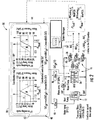
- FIG. 1 illustrates an exemplary HVAC system 10 that generally includes a capacity generation plant 12, a fluid circulation pump 14, ventilation equipment 16, and a controller 18.
- Capacity generation plant 12 conditions (i.e., heats/cools) a heat transfer fluid such as water and supplies the conditioned fluid to pump 14 via a conduit 20.
- Pump 14 subsequently supplies the conditioned fluid to ventilation equipment 16 (via a supply conduit 22) where the conditioned fluid is utilized to condition air forced through ventilation equipment 16.
- the conditioned air is then used to adjust the temperature of a building or structure associated with HVAC system 10.
- the fluid is then returned to capacity generation plant 12 via a return conduit 24 where the fluid is re-conditioned.
- Controller 18 is configured to coordinate the operation of capacity generation plant 12, pump 14, and ventilation equipment 16 with a demand of the building to reduce energy consumption through improved system efficiency.
- Capacity generation plant 12 may be, for example a heat pump, a chiller, or a boiler. However, capacity generation plant 12 may be any type of capacity generation plant that enables HVAC system 10 to function as described herein. Capacity generation plant 12 is configured to heat or cool a heat transfer fluid (e.g., water) to facilitate environmental conditioning of the buildings. As such, capacity generation plant 12 may be controlled to selectively adjust the temperature of the heat transfer fluid.
- a heat transfer fluid e.g., water
- Fluid circulation pump 14 is configured to supply the heat transfer fluid from capacity generation plant 12 to ventilation equipment 16. Pump 14 may be controlled to selectively adjust the pressure (or flow) of the heat transfer fluid.
- Ventilation equipment 16 may be any suitable equipment to supply conditioned air to selected zones or areas of the building.
- ventilation equipment 16 includes an air handling unit (AHU) 26 and a plurality of terminal units 28 connected via air ducts (not shown) to that AHU 26.
- AHU 26 is configured to receive outside air and supply the outside air (via a supply conduit 30) to one or more terminal units 28, which condition the air and supply it to the zones associated with the respective terminal unit(s) 28.
- the conditioned air is subsequently returned to AHU 26 via a return conduit 32 where it may be recycled or exhausted to the atmosphere.
- terminal units 28 are fan coil units.
- terminal units 28 may be any suitable equipment that enables HVAC system 10 to function as described herein.
- terminal units 28 may be fan coil units (FCUs), air terminal units (ATUs), variable air volume systems (VAV), or even AHUs.
- Controller 18 may be a system-level controller configured to adjust operational setpoints of capacity generation plant 12, pump 14, and ventilation equipment 16 based on load conditions and a thermal demand of the building (which may be estimated with an average difference between a measurement of an actual room air temperature and a setpoint room air temperature), as is described herein in more detail.
- a setpoint of plant 12 may be a fluid supply temperature
- a setpoint of pump 14 may be a fluid pressure or flow
- a setpoint of equipment 16 may be a valve or damper opening, a fan speed, a supply air flow and/or temperature setpoint for that equipment for a room or zone.
- controller refers to an application specific integrated circuit (ASIC), an electronic circuit, a processor (shared, dedicated, or group) and memory that executes one or more software or firmware programs, a combinational logic circuit, and/or other suitable components that provide the described functionality.
- ASIC application specific integrated circuit
- processor shared, dedicated, or group
- memory that executes one or more software or firmware programs, a combinational logic circuit, and/or other suitable components that provide the described functionality.
- controller 18 includes or is in signal communication with a coordination module 40 to facilitate adjusting the setpoints of capacity generation plant 12, pump 14, and ventilation equipment 16.
- coordination module 40 includes a cooling mode sub-module 42 and a heating mode sub-module 44. Cooling mode module 42 may be used when plant 12 is operated in a cooling mode, and second mode module 44 may be used when plant 12 is operated in a heating mode.
- Modules 42, 44 may include reference/lookup tables, graphs, formulas, and the like to facilitate determining the operational setpoints for components 12, 14, 16 when plant 12 is operated in the cooling or heating mode. For example, as illustrated in FIG. 2 , controller 18 determines setpoints for components 12 and 14 with a reference graph, and controller 18 determines setpoints for component 16 with a predetermined formula, all of which may be converted into formulas, look-up tables, or reference graphs.
- Modules 42, 44 facilitate determining setpoints of plant 12, pump 14, and equipment 16 for a specified thermal demand and load conditions, and controller 18 subsequently adjusts components 12, 14, and 16 to operate at those setpoints.
- the setpoints may be updated at predetermined time intervals (e.g., every five minutes).
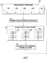
- FIG. 3 illustrates an exemplary method 100 of controlling HVAC system 10 that generally includes steps 120, 140, and 160.
- controller 18 determines the current building demand.
- controller 18 determines operational setpoints for HVAC components (e.g., 12, 14, 16) that result in efficient operation of the entire HVAC system 10.
- controller 18 sends one or more signals indicative of the determined setpoint(s) to the HVAC component(s).
- Method 100 may be executed at predetermined time intervals (e.g., every five minutes).
- controller 18 determines the current building demand, which is the total thermal heating or cooling demand required by the building/system served by the HVAC component under consideration (e.g., 12, 14, 16).
- the current building demand may be determined in various ways as represented by steps 120a-120e.
- These weighting factors Vi can be, for example, the unit rated capacity, the area or the volume of the zone served by the terminal unit 28, or a priority measure chosen by the building owner.
- the Vtot measure is the sum of all the weighting factors over all the relevant terminal units 28 installed in the building/system 10 (i.e.
- Vtot is equal to the total number of terminal units 28 installed, or the total building surface or volume served (through the terminal units) by the coordinated HVAC component, respectively.
- controller 18 determines the current building demand utilizing Equation (2), but where ⁇ T i is replaced by another relevant measure of the demand of terminal unit 28 (in the relevant heating/cooling mode). All signals measured at the terminal unit 28 could potentially be leveraged to determine its demand.
- value of demand may be: fan(s) speed(s), valve(s) or damper(s) openings, electrical heater(s) usage of the terminal unit, temperature(s) of the air going in or out of the unit, a measure of the capacity(ies) or power used by the terminal unit, a measure of temperatures and flows of fluids through the unit, or a combination thereof
- controller 18 determines the current building demand by utilizing HVAC component (e.g., plant 12, pump 14, equipment 16) measurements in addition to or instead of terminal unit measurements in steps 120a-120c.
- HVAC component e.g., plant 12, pump 14, equipment 16
- Such measurements of the HVAC component may be: the fan(s) speed(s), the valve(s) or damper(s) openings, the electrical heater(s) usage of the terminal unit, the temperature(s) of the air going in or out of the unit, the measure of the capacity(ies) or power used by the terminal unit, the measure of temperatures and flows of fluids through the unit, or a combination thereof.
- controller 18 determines the current building demand by a combination of one or more of steps 120a-120d.
- controller 18 may determine if capacity generation plant 12 is operating in a cooling mode or a heating mode, which may be utilized to differentiate between using cooling mode module 42 and heating mode module 44. Operating in the heating or cooling mode may be the system's default/legacy decision, or it may be a decision utilizing building demand measure estimated as described with the different substeps of step 120.
- ⁇ T He ⁇ t and ⁇ T Cool can be estimated as described with the different substeps of step 120, ⁇ T is estimated similarly but as the average demand over all the occupied zones (so regardless whether the corresponding terminal units 28 are in heating or cooling mode), and the threshold values ⁇ 0.25, 0.5, 0.75°C can be adjusted by the building owner or via an appropriate scaling depending on the HVAC system installed and/or the building characteristics
- controller 18 determines setpoints that will be sent to HVAC components by utilizing coordination module 40 and the determined building demand from step 120.
- Step 140 may include determining setpoints for capacity generation plant 12 (step 140a), pump 14 (step 140b), and ventilation equipment 16 (step 140c).
- controller 18 determines one or more setpoints that will be sent to capacity generation plant 12 through sub steps 142a and 144a.
- controller 18 determines whether to use coordination sub-module 42 or sub-module 44, depending on whether plant 12 is operated in the cooling or heating mode, respectively.
- controller 18 utilizes coordination module 40 (i.e., either sub-module 42 or 44 as chosen from step 142a) to determine the capacity generation plant setpoint based on the building demand determined in step 120.
- controller 18 sets capacity generation plant 12 to a minimum effort setpoint below a low demand threshold (La), increases (e.g., linearly) the effort setpoint from low demand threshold (La) to a high demand threshold (Ha), and sets the maximum effort setpoint beyond the high demand threshold (Ha).
- thresholds (La) and (Ha) define line (A) in the graphs illustrated in coordination module 40 ( FIG. 2 ).
- Demand thresholds (La) and (Ha) may be determined by operating terminal units 28 with hysteresis thresholds above or beyond which they start or stop their cooling/heating effort.
- thresholds of terminal units 28 are used to determine (La) and (Ha) thresholds (e.g., values of temperature differences).
- demand thresholds (La) and (Ha) may be related to percentages of building level effort determined in step 120 (e.g., 25%, 50%, and 75% of an average valve opening or of plant 12 or HVAC system total capacity).
- controller 18 determines one or more setpoints that will be sent to fluid circulation pump 14 through sub steps 142b and 144b.
- controller 18 determines whether to use either coordination sub-module 42 or 44 depending on whether plant 12 is operating in the cooling or heating mode, respectively.
- controller 18 utilizes coordination module 40 (i.e., sub-module 42 or 44 as chosen in step 142b) to determine the capacity generation plant setpoint based on the building demand determined in step 120.
- controller 18 sets pump 14 to a minimum effort setpoint below a low demand threshold (Lb), and increases (e.g., linearly(the effort setpoint from the low demand threshold (Lb) to a high demand threshold (Hb), and sets the maximum effort setpoint beyond the high demand threshold (Hb).
- Lb low demand threshold
- Hb high demand threshold
- thresholds (Lb), and (Hb) define line (B) in the graphs illustrated in coordination module 40 ( FIG. 2 ).
- Demand thresholds (Lb) and (Hb) may be determined by operating terminal units 28 with hysteresis thresholds above or beyond which they start or stop their cooling/heating effort.
- thresholds of terminal units 28 are used to determine (Lb) and (Hb) thresholds (e.g., values of temperature differences).
- demand thresholds (Lb) and (Hb) may be related to percentages of building level effort determined in step 120 (e.g., 25%, 50%, and 75% of an average valve opening or of the plant or HVAC system total capacity).
- This exemplary choice implies that the effort setpoint of fluid circulation pump 14 is increased to its maximum before the effort setpoint of plant 12 is increased.
- controller 18 determines one or more setpoints that will be sent to ventilation equipment 16 that treats fresh air from outside prior to sending it to the building such as AHU 26, which will be used for exemplary purposes.
- controller 18 determines whether to use either coordination sub-module 42 or 44 depending on whether plant 12 is operated in the cooling or heating mode, respectively. A third alternative may be used if plant 12 is off, as described herein in more detail.
- controller 18 determines a supply air temperature setpoint (SATsp) of AHU 26 sufficient to prevent overcooling or overheating a specific area/zone (in the determined heating/cooling mode), as describe herein in more detail.
- SATsp supply air temperature setpoint
- SATsp min RATsp + air duct losses / gains , where min(RATsp) is the minimum room air temperature setpoint amongst all areas/zones served by that AHU.
- SATsp mean RATsp + air duct losses / gains , where mean(RATsp) is the average room air temperature setpoint amongst all areas/zones served by that AHU.
- controller 18 sends the determined setpoints to the associated HVAC component and operates those components at the determined setpoints.
- the setpoint(s) determined for step 140a are sent to capacity generation plant 12
- the setpoint(s) determined for steps 140b are sent to fluid circulation pump 14
- the setpoint(s) determined for steps 140c are sent to ventilation equipment 16 that treats outside air prior to sending throughout the building.
- a filter 46 FIG. 2
- Control may then return to step 120.
- controller 18 is programmed to perform the steps described herein.
- HVAC system components such as a capacity generation plant, a fluid circulation pump, and ventilation equipment.
- the control coordinates the effort of the various components with respect to an aggregated measure of the demand on terminal units that are connected to the components.
- the control obtains an estimate of the heating/cooling aggregated whole building demand, computes component setpoints based on the building demand, filters the setpoints, and sends the setpoints to the associated components to operate those components at the determined setpoints.
- the components setpoints are periodically adjusted to meet the building demand resulting in more efficient component operation and energy savings.
Description
- The subject matter disclosed herein relates to HVAC systems and, more specifically, to control of HVAC system equipment.
- In some known heating, ventilation, and air conditioning (HVAC) systems, equipment setpoints are typically fixed or weather compensated (i.e., determined based on outdoor air temperature) without any feedback from other systems. As such, the produced heating/cooling capacity may deviate from a building demand corresponding to a desired building comfort level. Similarly, the authority of the capacity production and distribution system, which is determined via its fluids flows/pressures and temperatures, may be unnecessarily high, so a lower authority could be sufficient to maintain the building comfort. The capacity deviations and the high authorities may result in increased energy consumption and cost.
-
US 20110137468 A1 discloses a cooling system for providing conditioned air to a facility includes a chiller or other cooling subsystem, a cooling tower subsystem and one or more air handling units or process cooling units. The cooling subsystem may advantageously include one or more chillers (e.g., variable speed chillers, constant speed chillers, absorption chillers, etc.) and chilled fluid pumps. - Accordingly, it is desirable to provide a control system to improve HVAC system efficiency and maintain building comfort levels.
- The invention is defined by
independent claims 1 and 5. - In one aspect, a control system for an HVAC system having a plurality of HVAC components operably associated with one or more terminal units is provided. The control system includes a coordination module and a controller having a processor and a memory, the controller operably associated with the coordination module and in signal communication with the plurality of HVAC components. The controller is configured to determine an aggregated thermal demand of the HVAC system, determine, with the coordination module, an operational setpoint for at least one HVAC component of the plurality of HVAC components based on the determined aggregated thermal demand, and send a signal indicative of each determined operational setpoint to each associated HVAC component of the plurality of HVAC components.
- In addition to one or more of the features described above, or as an alternative, further embodiments may include: wherein the controller is configured to update the operational setpoints at predetermined time intervals; wherein the plurality of HVAC components comprises a capacity generation plant, a fluid circulation pump, and ventilation equipment; wherein the ventilation equipment comprises an air handling unit; wherein the coordination module includes a cooling mode module and a heating mode module; and/or wherein determining the aggregated thermal demand of the HVAC system comprises determining an aggregated thermal demand of the one or more terminal units. Exemplary embodiments of the invention may include any of these features alone or in any subset.
- In another aspect, an HVAC system is provided. The system includes a plurality of HVAC components, at least one terminal unit associated with each HVAC component of the plurality of HVAC components, a coordination module, and a controller having a processor and a memory, the controller operably associated with the coordination module and in signal communication with the plurality of HVAC components and associated terminal units. The controller is configured to determine an aggregated thermal demand of the HVAC system, determine, with the coordination module, an operational setpoint for at least one HVAC component of the plurality of HVAC components based on the determined aggregated thermal demand, and send a signal indicative of each determined operational setpoint to each associated HVAC component of the plurality of HVAC components.
- In addition to one or more of the features described above, or as an alternative, further embodiments may include: wherein the controller is configured to update the operational setpoints at predetermined time intervals; wherein the plurality of HVAC components comprises a capacity generation plant, a fluid circulation pump, and ventilation equipment; wherein the ventilation equipment comprises an air handling unit; wherein the coordination module includes a cooling mode module and a heating mode module; and/or wherein determining the aggregated thermal demand of the HVAC system comprises determining an aggregated thermal demand of the one or more terminal units. Exemplary embodiments of the invention may include any of these features alone or in any subset.
- In yet another aspect, provided herein is a method of controlling an HVAC system having a plurality of HVAC components, at least one terminal unit associated with each HVAC component of the plurality of HVAC components, a coordination module, and a controller operably associated with the coordination module and in signal communication with the plurality of HVAC components and associated terminal units. The method includes determining an aggregated thermal demand of the HVAC system, determining, with the coordination module, an operational setpoint for at least one HVAC component of the plurality of HVAC components based on the determined aggregated thermal demand, and subsequently operating each HVAC component of the plurality of HVAC components at the determined operational setpoint.
- In addition to one or more of the features described above, or as an alternative, further embodiments may include: updating the operational setpoints at predetermined time intervals; wherein the plurality of HVAC components comprises a capacity generation plant, a fluid circulation pump, and ventilation equipment; wherein the ventilation equipment comprises an air handling unit; wherein the coordination module includes a cooling mode sub-module and a heating mode sub-module; wherein the operational setpoint for the capacity generation plant is a water temperature, the operational setpoint for the pump is a water pressure, and the operational setpoint for the air handling unit is a supply air temperature; wherein said determining an aggregated thermal demand comprises determining an aggregated thermal demand of the one or more terminal units; and/or wherein said determining an aggregated thermal demand of the HVAC system comprises determining if the capacity generation plant is being operated in a cooling mode or a heating mode, measuring an air temperature of the zone, and dividing the product of the number of terminal units of the one or more terminal units operating in the cooling mode or the heating mode and the difference between a zone air temperature setpoint and a measured zone air temperature, by the total number of terminal units associated with the plurality of HVAC components. Exemplary embodiments of the invention may include any of these features alone or in any subset.
- The foregoing and other features, and advantages of embodiments are apparent from the following detailed description taken in conjunction with the accompanying drawings in which:
-
FIG. 1 is a schematic view of an exemplary HVAC system; -
FIG. 2 is an exemplary control diagram that may be used for the system shown inFIG. 1 ; and -
FIG. 3 is a flow chart illustrating an exemplary method of controlling the system shown inFIG. 1 . -
FIG. 1 illustrates anexemplary HVAC system 10 that generally includes acapacity generation plant 12, afluid circulation pump 14,ventilation equipment 16, and acontroller 18. Capacity generation plant 12 conditions (i.e., heats/cools) a heat transfer fluid such as water and supplies the conditioned fluid to pump 14 via aconduit 20.Pump 14 subsequently supplies the conditioned fluid to ventilation equipment 16 (via a supply conduit 22) where the conditioned fluid is utilized to condition air forced throughventilation equipment 16. The conditioned air is then used to adjust the temperature of a building or structure associated withHVAC system 10. The fluid is then returned tocapacity generation plant 12 via areturn conduit 24 where the fluid is re-conditioned.Controller 18 is configured to coordinate the operation ofcapacity generation plant 12,pump 14, andventilation equipment 16 with a demand of the building to reduce energy consumption through improved system efficiency. -
Capacity generation plant 12 may be, for example a heat pump, a chiller, or a boiler. However,capacity generation plant 12 may be any type of capacity generation plant that enablesHVAC system 10 to function as described herein.Capacity generation plant 12 is configured to heat or cool a heat transfer fluid (e.g., water) to facilitate environmental conditioning of the buildings. As such,capacity generation plant 12 may be controlled to selectively adjust the temperature of the heat transfer fluid. -
Fluid circulation pump 14 is configured to supply the heat transfer fluid fromcapacity generation plant 12 toventilation equipment 16.Pump 14 may be controlled to selectively adjust the pressure (or flow) of the heat transfer fluid. -
Ventilation equipment 16 may be any suitable equipment to supply conditioned air to selected zones or areas of the building. For example, in the illustrated embodiment,ventilation equipment 16 includes an air handling unit (AHU) 26 and a plurality ofterminal units 28 connected via air ducts (not shown) to that AHU 26. AHU 26 is configured to receive outside air and supply the outside air (via a supply conduit 30) to one ormore terminal units 28, which condition the air and supply it to the zones associated with the respective terminal unit(s) 28. The conditioned air is subsequently returned to AHU 26 via areturn conduit 32 where it may be recycled or exhausted to the atmosphere. In the illustrated embodiment,terminal units 28 are fan coil units. However,terminal units 28 may be any suitable equipment that enablesHVAC system 10 to function as described herein. For example,terminal units 28 may be fan coil units (FCUs), air terminal units (ATUs), variable air volume systems (VAV), or even AHUs. -
Controller 18 may be a system-level controller configured to adjust operational setpoints ofcapacity generation plant 12,pump 14, andventilation equipment 16 based on load conditions and a thermal demand of the building (which may be estimated with an average difference between a measurement of an actual room air temperature and a setpoint room air temperature), as is described herein in more detail. For example, a setpoint ofplant 12 may be a fluid supply temperature, a setpoint ofpump 14 may be a fluid pressure or flow, and a setpoint ofequipment 16 may be a valve or damper opening, a fan speed, a supply air flow and/or temperature setpoint for that equipment for a room or zone. As used herein, the term controller refers to an application specific integrated circuit (ASIC), an electronic circuit, a processor (shared, dedicated, or group) and memory that executes one or more software or firmware programs, a combinational logic circuit, and/or other suitable components that provide the described functionality. - In the exemplary embodiment,
controller 18 includes or is in signal communication with acoordination module 40 to facilitate adjusting the setpoints ofcapacity generation plant 12,pump 14, andventilation equipment 16. As illustrated inFIG. 2 ,coordination module 40 includes acooling mode sub-module 42 and aheating mode sub-module 44.Cooling mode module 42 may be used whenplant 12 is operated in a cooling mode, andsecond mode module 44 may be used whenplant 12 is operated in a heating mode. -
Modules components plant 12 is operated in the cooling or heating mode. For example, as illustrated inFIG. 2 ,controller 18 determines setpoints forcomponents controller 18 determines setpoints forcomponent 16 with a predetermined formula, all of which may be converted into formulas, look-up tables, or reference graphs. -
Modules plant 12,pump 14, andequipment 16 for a specified thermal demand and load conditions, andcontroller 18 subsequently adjustscomponents -
FIG. 3 illustrates anexemplary method 100 of controllingHVAC system 10 that generally includessteps step 120,controller 18 determines the current building demand. Atstep 140,controller 18 determines operational setpoints for HVAC components (e.g., 12, 14, 16) that result in efficient operation of theentire HVAC system 10. Atstep 160,controller 18 sends one or more signals indicative of the determined setpoint(s) to the HVAC component(s).Method 100 may be executed at predetermined time intervals (e.g., every five minutes). - At
step 120,controller 18 determines the current building demand, which is the total thermal heating or cooling demand required by the building/system served by the HVAC component under consideration (e.g., 12, 14, 16). The current building demand may be determined in various ways as represented bysteps 120a-120e. - For example, at
step 120a,controller 18 determines the current building demand by:
terminal units 28 in cooling or heating demand, respectively, ΔT i = RATSP,i - RATi is the difference between the room/zone air temperature setpoint RATSP,i and the measured room air temperature RATi (with i referring to the terminal unit number), and NtotFCUs being the total number ofterminal units 28 being connected to and served by the HVAC component (i.e., the fixed number ofterminal units 28, which is always larger or equal to the number ofunits 28 currently in heating or cooling demand). - At
step 120b,controller 18 determines the current building demand by:
terminal unit 28, or a priority measure chosen by the building owner. The Vtot measure is the sum of all the weighting factors over all the relevantterminal units 28 installed in the building/system 10 (i.e. connected to the HVAC component being coordinated with these terminal units 28). For the particular cases where Vi is equal to 1, or the area of the zone or the volume of the zone served by thatterminal unit 28, then Vtot is equal to the total number ofterminal units 28 installed, or the total building surface or volume served (through the terminal units) by the coordinated HVAC component, respectively. - At
step 120c,controller 18 determines the current building demand utilizing Equation (2), but where ΔTi is replaced by another relevant measure of the demand of terminal unit 28 (in the relevant heating/cooling mode). All signals measured at theterminal unit 28 could potentially be leveraged to determine its demand. In particular, such value of demand may be: fan(s) speed(s), valve(s) or damper(s) openings, electrical heater(s) usage of the terminal unit, temperature(s) of the air going in or out of the unit, a measure of the capacity(ies) or power used by the terminal unit, a measure of temperatures and flows of fluids through the unit, or a combination thereof - At
step 120d,controller 18 determines the current building demand by utilizing HVAC component (e.g.,plant 12, pump 14, equipment 16) measurements in addition to or instead of terminal unit measurements insteps 120a-120c. Such measurements of the HVAC component may be: the fan(s) speed(s), the valve(s) or damper(s) openings, the electrical heater(s) usage of the terminal unit, the temperature(s) of the air going in or out of the unit, the measure of the capacity(ies) or power used by the terminal unit, the measure of temperatures and flows of fluids through the unit, or a combination thereof. - At
step 120e,controller 18 determines the current building demand by a combination of one or more ofsteps 120a-120d. - At
step 130,controller 18 may determine ifcapacity generation plant 12 is operating in a cooling mode or a heating mode, which may be utilized to differentiate between using coolingmode module 42 andheating mode module 44. Operating in the heating or cooling mode may be the system's default/legacy decision, or it may be a decision utilizing building demand measure estimated as described with the different substeps ofstep 120. One example is given with the following set of rules: Start heating if (ΔT > 0 and ΔTHeat > 0.75°C), start cooling if (ΔT < 0 and ΔTCool < -0.75°C), stop heating if (ΔT < 0 or ΔTHeαt < 0.25°C), stop cooling if (ΔT > 0 or ΔTCool > -0.25°C), changeover from cooling to heating if (ΔT > 0 and ΔTHeat > 0.5°C), and changeover from heating to cooling if (ΔT < 0 and ΔTCool < -0.5°C). ΔTHeαt and ΔTCool can be estimated as described with the different substeps ofstep 120, ΔT is estimated similarly but as the average demand over all the occupied zones (so regardless whether the correspondingterminal units 28 are in heating or cooling mode), and the threshold values ±0.25, 0.5, 0.75°C can be adjusted by the building owner or via an appropriate scaling depending on the HVAC system installed and/or the building characteristics - At
step 140,controller 18 determines setpoints that will be sent to HVAC components by utilizingcoordination module 40 and the determined building demand fromstep 120. Step 140 may include determining setpoints for capacity generation plant 12 (step 140a), pump 14 (step 140b), and ventilation equipment 16 (step 140c). - At
step 140a,controller 18 determines one or more setpoints that will be sent tocapacity generation plant 12 throughsub steps step 142a,controller 18 determines whether to usecoordination sub-module 42 or sub-module 44, depending on whetherplant 12 is operated in the cooling or heating mode, respectively. Then, atstep 144a,controller 18 utilizes coordination module 40 (i.e., either sub-module 42 or 44 as chosen fromstep 142a) to determine the capacity generation plant setpoint based on the building demand determined instep 120. More specifically, atstep 142a,controller 18 setscapacity generation plant 12 to a minimum effort setpoint below a low demand threshold (La), increases (e.g., linearly) the effort setpoint from low demand threshold (La) to a high demand threshold (Ha), and sets the maximum effort setpoint beyond the high demand threshold (Ha). For example, thresholds (La) and (Ha) define line (A) in the graphs illustrated in coordination module 40 (FIG. 2 ). - Demand thresholds (La) and (Ha) may be determined by operating
terminal units 28 with hysteresis thresholds above or beyond which they start or stop their cooling/heating effort. In the exemplary embodiment, thresholds ofterminal units 28 are used to determine (La) and (Ha) thresholds (e.g., values of temperature differences). Alternatively, demand thresholds (La) and (Ha) may be related to percentages of building level effort determined in step 120 (e.g., 25%, 50%, and 75% of an average valve opening or ofplant 12 or HVAC system total capacity). - Similarly, at
step 140b,controller 18 determines one or more setpoints that will be sent tofluid circulation pump 14 throughsub steps step 142b,controller 18 determines whether to use eithercoordination sub-module plant 12 is operating in the cooling or heating mode, respectively. Then atstep 144b,controller 18 utilizes coordination module 40 (i.e., sub-module 42 or 44 as chosen instep 142b) to determine the capacity generation plant setpoint based on the building demand determined instep 120. More specifically, atstep 142b,controller 18 sets pump 14 to a minimum effort setpoint below a low demand threshold (Lb), and increases (e.g., linearly(the effort setpoint from the low demand threshold (Lb) to a high demand threshold (Hb), and sets the maximum effort setpoint beyond the high demand threshold (Hb). For example, thresholds (Lb), and (Hb) define line (B) in the graphs illustrated in coordination module 40 (FIG. 2 ). - Demand thresholds (Lb) and (Hb) may be determined by operating
terminal units 28 with hysteresis thresholds above or beyond which they start or stop their cooling/heating effort. In the exemplary embodiment, thresholds ofterminal units 28 are used to determine (Lb) and (Hb) thresholds (e.g., values of temperature differences). Alternatively, demand thresholds (Lb) and (Hb) may be related to percentages of building level effort determined in step 120 (e.g., 25%, 50%, and 75% of an average valve opening or of the plant or HVAC system total capacity). -
FIG. 2 illustrates an exemplary threshold choice for which (Lb) = (L), (Hb) = (La) = (M), and (Ha) = (H), wherein (L) is a global Low Threshold, (M) is a global Medium Threshold, and (H) is a global High Threshold. This exemplary choice implies that the effort setpoint offluid circulation pump 14 is increased to its maximum before the effort setpoint ofplant 12 is increased. - At step 140c,
controller 18 determines one or more setpoints that will be sent toventilation equipment 16 that treats fresh air from outside prior to sending it to the building such asAHU 26, which will be used for exemplary purposes. Atstep 142c,controller 18 determines whether to use eithercoordination sub-module plant 12 is operated in the cooling or heating mode, respectively. A third alternative may be used ifplant 12 is off, as described herein in more detail.. Atstep 144c,controller 18 determines a supply air temperature setpoint (SATsp) ofAHU 26 sufficient to prevent overcooling or overheating a specific area/zone (in the determined heating/cooling mode), as describe herein in more detail. - When
capacity generation plant 12 is operated in the cooling mode, SATsp is determined by:

value 1. - When
capacity generation plant 12 is operated in the heating mode, SATsp is determined by:
- When
capacity generation plant 12 is off, SATsp is determined by:
- At
step 160,controller 18 sends the determined setpoints to the associated HVAC component and operates those components at the determined setpoints. For example, the setpoint(s) determined forstep 140a are sent tocapacity generation plant 12, the setpoint(s) determined forsteps 140b are sent tofluid circulation pump 14, and the setpoint(s) determined for steps 140c are sent toventilation equipment 16 that treats outside air prior to sending throughout the building. In some embodiments, a filter 46 (FIG. 2 ) may be used to smooth the setpoint change to facilitate preventing operational issues that may result from a sudden, large setpoint change. Control may then return to step 120. As such,controller 18 is programmed to perform the steps described herein. - Described herein are systems and methods for controlling HVAC system components such as a capacity generation plant, a fluid circulation pump, and ventilation equipment. The control coordinates the effort of the various components with respect to an aggregated measure of the demand on terminal units that are connected to the components. The control obtains an estimate of the heating/cooling aggregated whole building demand, computes component setpoints based on the building demand, filters the setpoints, and sends the setpoints to the associated components to operate those components at the determined setpoints. As such, the components setpoints are periodically adjusted to meet the building demand resulting in more efficient component operation and energy savings.
- While the disclosure has been described in detail in connection with only a limited number of embodiments, it should be readily understood that the disclosure is not limited to such disclosed embodiments. Rather, the disclosure can be modified to incorporate any number of variations, alterations, substitutions or equivalent arrangements not heretofore described, but which are commensurate with the scope of the disclosure. Additionally, while various embodiments have been described, it is to be understood that aspects of the disclosure may include only some of the described embodiments. Accordingly, the disclosure is not to be seen as limited by the foregoing description, but is only limited by the scope of the appended claims.
Claims (10)
- HVAC system (10) comprising:a plurality of HVAC components (12, 14, 16);at least one terminal unit (28) operably associated with each HVAC component (12, 14, 16) of the plurality of HVAC components (12, 14, 16);a control system comprising:a coordination module (40); anda controller (18) having a processor and a memory, the controller (18) operably associated with the coordination module (40) and in signal communication with the plurality of HVAC components (12, 14, 16), the controller (18) configured:to determine an aggregated thermal demand of the HVAC system (10);to determine, with the coordination module (40), an operational setpoint for at least one HVAC component (12, 14, 16) of the plurality of HVAC components (12, 14, 16) based on the determined aggregated thermal demand; andto send a signal indicative of each determined operational setpoint to each associated HVAC component (12, 14, 16) of the plurality of HVAC components (12, 14, 16),wherein the plurality of HVAC components (12, 14, 16) comprises a capacity generation plant (12), a fluid circulation pump (14), and ventilation equipment (16), andwherein the coordination module (40) includes a cooling mode module (42) and a heating mode module (44),characterized in that the controller (18) is configuredto determine if the capacity generation plant (12) is operating in a cooling mode or a heating mode, andto determine whether to use coordination sub-module (42) or sub-module (44), depending on whether the capacity generation plant (12) is operated in a cooling or a heating mode, andwherein the determining of the operational setpoint for at least one HVAC component (12, 14, 16) comprises at least one of:determining one or more setpoints to be sent to the capacity generation plant (12), wherein the controller (18) is configured to set the capacity generation plant (12) to a minimum effort setpoint below a low demand threshold (La), increase the effort setpoint from low demand threshold (La) to a high demand threshold (Ha), and to set a maximum effort setpoint beyond the high demand threshold (Ha),determining one or more setpoints to be sent to the fluid circulation pump (14), wherein the controller (18) is configured to set the pump (14) to a minimum effort setpoint below a low demand threshold (Lb), increase the effort setpoint from the low demand threshold (Lb) to a high demand threshold (Hb), and to set a maximum effort setpoint beyond the high demand threshold (Hb), anddetermining one or more setpoints to be sent to the ventilation equipment (16) that treats fresh air from outside, wherein when the capacity generation plant (12) is operated in the cooling mode, a supply air setpoint (SATsp) is determined by the sum of the maximum room air temperature setpoint amongst all areas/zones and the air duct losses/gains, and wherein when the capacity generation plant (12) is operated in the heating mode, a supply air setpoint (SATsp) is determined by the sum of the minimum room air temperature setpoint amongst all areas/zones and the air duct losses/gains.
- HVAC system (10) of claim 1, wherein the controller (18) is configured to update the operational setpoints at predetermined time intervals.
- HVAC system (10) of claim 1, wherein the ventilation equipment comprises an air handling unit.
- HVAC system (10) of any one of the preceding claims, wherein determining the aggregated thermal demand of the HVAC system (10) comprises determining an aggregated thermal demand of the one or more terminal units (28).
- Method of controlling an HVAC system (10) having a plurality of HVAC components (12, 14, 16), at least one terminal unit (28) associated with each HVAC component (12, 14, 16) of the plurality of HVAC components (12, 14, 16), a coordination module (40), and a controller (18) operably associated with the coordination module (40) and in signal communication with the plurality of HVAC components (12, 14, 16) and associated terminal units (28), the method comprising:determining an aggregated thermal demand of the HVAC system (10);determining, with the coordination module (40), an operational setpoint for at least one HVAC component (12, 14, 16) of the plurality of HVAC components (12, 14, 16) based on the determined aggregated thermal demand; andsubsequently operating each HVAC component (12, 14, 16) of the plurality of HVAC components (12, 14, 16) at the determined operational setpoint,wherein the coordination module (40) includes a cooling mode sub-module (42) and a heating mode sub-module (44),and wherein the plurality of HVAC components (12, 14, 16) comprises a capacity generation plant, a fluid circulation pump, and ventilation equipment,characterized in that the controller (18) is configuredto determine if the capacity generation plant (12) is operating in a cooling mode or a heating mode, andto determine whether to use coordination sub-module (42) or sub-module (44), depending on whether the capacity generation plant (12) is operated in a cooling or a heating mode, andwherein the determining of the operational setpoint for at least one HVAC component (12, 14, 16) comprises at least one of:determining one or more setpoints to be sent to the capacity generation plant (12), wherein the controller (18) is configured to set the capacity generation plant (12) to a minimum effort setpoint below a low demand threshold (La), increase the effort setpoint from low demand threshold (La) to a high demand threshold (Ha), and to set a maximum effort setpoint beyond the high demand threshold (Ha),determining one or more setpoints to be sent to the fluid circulation pump (14), wherein the controller (18) is configured to set the pump (14) to a minimum effort setpoint below a low demand threshold (Lb), increase the effort setpoint from the low demand threshold (Lb) to a high demand threshold (Hb), and to set a maximum effort setpoint beyond the high demand threshold (Hb), anddetermining one or more setpoints to be sent to the ventilation equipment (16) that treats fresh air from outside, wherein when capacity generation plant (12) is operated in the cooling mode, a supply air setpoint (SATsp) is determined by the sum of the maximum room air temperature setpoint amongst all areas/zones and the air duct losses/gains, and wherein when the capacity generation plant (12) is operated in the heating mode, a supply air setpoint (SATsp) is determined by the sum of the minimum room air temperature setpoint amongst all areas/zones and the air duct losses/gains.
- Method of claim 5, further comprising updating the operational setpoints at predetermined time intervals.
- Method of any one of claims 5 or 6, wherein said determining an aggregated thermal demand comprises determining an aggregated thermal demand of the one or more terminal units (28).
- Method of claim 5, wherein the ventilation equipment comprises an air handling unit.
- Method of claim 8, wherein the operational setpoint for the capacity generation plant is a water temperature, the operational setpoint for the pump is a water pressure, and the operational setpoint for the air handling unit is a supply air temperature.
- Method of any one of claims 5 to 9, wherein said determining an aggregated thermal demand of the HVAC system (10) comprises:determining if the capacity generation plant is being operated in a cooling mode or a heating mode;measuring an air temperature of the zone; anddividing the product of the number of terminal units (28) of the one or more terminal units (28) operating in the cooling mode or the heating mode and the difference between a zone air temperature setpoint and a measured zone air temperature, by the total number of terminal units (28) associated with the plurality of HVAC components (12, 14, 16).
Applications Claiming Priority (1)
| Application Number | Priority Date | Filing Date | Title |
|---|---|---|---|
| US14/723,911 US9851727B2 (en) | 2015-05-28 | 2015-05-28 | Coordinated control of HVAC system using aggregated system demand |
Publications (2)
| Publication Number | Publication Date |
|---|---|
| EP3098529A1 EP3098529A1 (en) | 2016-11-30 |
| EP3098529B1 true EP3098529B1 (en) | 2020-03-25 |
Family
ID=56087139
Family Applications (1)
| Application Number | Title | Priority Date | Filing Date |
|---|---|---|---|
| EP16171315.1A Active EP3098529B1 (en) | 2015-05-28 | 2016-05-25 | Coordinated control of hvac system using aggregated system demand |
Country Status (3)
| Country | Link |
|---|---|
| US (1) | US9851727B2 (en) |
| EP (1) | EP3098529B1 (en) |
| ES (1) | ES2797798T3 (en) |
Families Citing this family (3)
| Publication number | Priority date | Publication date | Assignee | Title |
|---|---|---|---|---|
| US11221156B2 (en) * | 2018-04-24 | 2022-01-11 | Johnson Controls Tyco IP Holdings LLP | Central plant control system with decaying capacity adjustment |
| US11713895B2 (en) | 2019-01-14 | 2023-08-01 | Research Products Corporation | Multi-zone environmental control system |
| US11892188B2 (en) | 2021-05-30 | 2024-02-06 | Trane International Inc. | Capacity control for HVAC system |
Family Cites Families (68)
| Publication number | Priority date | Publication date | Assignee | Title |
|---|---|---|---|---|
| US2012228A (en) | 1935-08-20 | Purification of l-n-methyl-x- | ||
| US4843084A (en) * | 1987-02-12 | 1989-06-27 | Parker Electronics, Inc. | Thermostat control system |
| US5144812A (en) * | 1991-06-03 | 1992-09-08 | Carrier Corporation | Outdoor fan control for variable speed heat pump |
| US6095426A (en) | 1997-11-07 | 2000-08-01 | Siemens Building Technologies | Room temperature control apparatus having feedforward and feedback control and method |
| US6033302A (en) | 1997-11-07 | 2000-03-07 | Siemens Building Technologies, Inc. | Room pressure control apparatus having feedforward and feedback control and method |
| US6066843A (en) | 1998-04-06 | 2000-05-23 | Lightstat, Inc. | Light discriminator for a thermostat |
| US6145751A (en) * | 1999-01-12 | 2000-11-14 | Siemens Building Technologies, Inc. | Method and apparatus for determining a thermal setpoint in a HVAC system |
| US7992630B2 (en) | 2001-03-12 | 2011-08-09 | Davis Energy Group, Inc. | System and method for pre-cooling of buildings |
| US7398821B2 (en) | 2001-03-12 | 2008-07-15 | Davis Energy Group | Integrated ventilation cooling system |
| AU2002310859B2 (en) | 2001-05-16 | 2007-09-06 | Uniflair Spa | Air-conditioning system |
| US6792766B2 (en) | 2002-10-04 | 2004-09-21 | Cascade Manufacturing, L.P. | Zone demand controlled dual air conditioning system and controller therefor |
| US20050087616A1 (en) * | 2003-10-17 | 2005-04-28 | Attridge Russell G. | Thermal balance temperature control system |
| US7216016B2 (en) * | 2004-01-20 | 2007-05-08 | Carrier Corporation | Failure mode for HVAC system |
| US20050194456A1 (en) | 2004-03-02 | 2005-09-08 | Tessier Patrick C. | Wireless controller with gateway |
| US7905103B2 (en) | 2004-09-30 | 2011-03-15 | Danfoss A/S | Model prediction controlled refrigeration system |
| US9459015B2 (en) * | 2005-05-06 | 2016-10-04 | John Chris Karamanos | HVAC system and zone control unit |
| US7894943B2 (en) | 2005-06-30 | 2011-02-22 | Sloup Charles J | Real-time global optimization of building setpoints and sequence of operation |
| EP1934665B1 (en) | 2005-10-14 | 2015-06-17 | Siemens Schweiz AG | Device for controlling the room temperature in a building using a predictive control device |
| US7644869B2 (en) | 2005-12-28 | 2010-01-12 | Honeywell International Inc. | Auxiliary stage control of multistage thermostats |
| EP1987402A1 (en) | 2006-02-24 | 2008-11-05 | Siemens Aktiengesellschaft | Model-based predictive regulation of a building energy system |
| US7890215B2 (en) | 2006-12-22 | 2011-02-15 | Duncan Scot M | Optimized control system for cooling systems |
| US7774102B2 (en) * | 2007-06-22 | 2010-08-10 | Emerson Electric Co. | System including interactive controllers for controlling operation of climate control system |
| US8019567B2 (en) | 2007-09-17 | 2011-09-13 | Ecofactor, Inc. | System and method for evaluating changes in the efficiency of an HVAC system |
| US8010237B2 (en) | 2008-07-07 | 2011-08-30 | Ecofactor, Inc. | System and method for using ramped setpoint temperature variation with networked thermostats to improve efficiency |
| US9002761B2 (en) | 2008-10-08 | 2015-04-07 | Rey Montalvo | Method and system for automatically adapting end user power usage |
| US8600559B2 (en) * | 2008-10-27 | 2013-12-03 | Lennox Industries Inc. | Method of controlling equipment in a heating, ventilation and air conditioning network |
| ES2432153T3 (en) | 2008-10-31 | 2013-12-02 | Optimum Energy, Llc | Systems and methods to control the efficiency of energy consumption |
| US9020647B2 (en) | 2009-03-27 | 2015-04-28 | Siemens Industry, Inc. | System and method for climate control set-point optimization based on individual comfort |
| US9121628B2 (en) | 2009-06-02 | 2015-09-01 | Nortek Global Hvac Llc | Heat pumps with unequal cooling and heating capacities for climates where demand for cooling and heating are unequal, and method of adapting and distributing such heat pumps |
| US8532839B2 (en) | 2009-06-22 | 2013-09-10 | Johnson Controls Technology Company | Systems and methods for statistical control and fault detection in a building management system |
| CN102812303B (en) | 2009-12-16 | 2016-03-30 | 国家科学和工业研究组织 | HVAC control system and method |
| JP2011201294A (en) * | 2010-03-01 | 2011-10-13 | Ricoh Co Ltd | Control apparatus of image forming apparatus for continuous paper, image forming apparatus for continuous paper, control method, and control program |
| US9002481B2 (en) | 2010-07-14 | 2015-04-07 | Honeywell International Inc. | Building controllers with local and global parameters |
| US20120031984A1 (en) | 2010-08-03 | 2012-02-09 | Massachusetts Institute Of Technology | Personalized Building Comfort Control |
| US8560127B2 (en) | 2011-01-13 | 2013-10-15 | Honeywell International Inc. | HVAC control with comfort/economy management |
| WO2012112324A1 (en) | 2011-02-14 | 2012-08-23 | Carrier Corporation | Environmental control system |
| WO2013019537A2 (en) | 2011-07-29 | 2013-02-07 | Carrier Corporation | Hvac systems |
| US20150178865A1 (en) | 2011-09-20 | 2015-06-25 | The Trustees Of Columbia University In The City Of New York | Total property optimization system for energy efficiency and smart buildings |
| WO2013043863A1 (en) | 2011-09-20 | 2013-03-28 | The Trustees Of Columbia University In The City Of New York | Adaptive stochastic controller for energy efficiency and smart buildings |
| US8843238B2 (en) | 2011-09-30 | 2014-09-23 | Johnson Controls Technology Company | Systems and methods for controlling energy use in a building management system using energy budgets |
| US9822989B2 (en) | 2011-12-12 | 2017-11-21 | Vigilent Corporation | Controlling air temperatures of HVAC units |
| US8977405B2 (en) | 2011-12-13 | 2015-03-10 | Patrick Andrew Shiel | Continuous optimization energy reduction process in commercial buildings |
| US9377212B2 (en) | 2011-12-16 | 2016-06-28 | Lennox Industries Inc. | Time-based setback recovery |
| US9175869B2 (en) | 2011-12-21 | 2015-11-03 | Lennox Industries Inc. | Uniform HVAC comfort across multiple systems |
| EP2804347B1 (en) | 2011-12-28 | 2018-11-07 | Lutron Electronics Co., Inc. | Load control system for controlling an electrical load |
| US9612591B2 (en) | 2012-01-23 | 2017-04-04 | Earth Networks, Inc. | Optimizing and controlling the energy consumption of a building |
| US9494953B2 (en) | 2012-03-30 | 2016-11-15 | Emerson Climate Technologies Retail Solutions, Inc. | Control system and method for multi-stage heating and cooling system with minimum on time and off time |
| DE102012011519A1 (en) | 2012-06-08 | 2013-12-12 | Yack SAS | air conditioning |
| CA2884883C (en) | 2012-09-13 | 2017-09-05 | Siemens Corporation | Social learning softthermostat for commercial buildings |
| WO2014047605A1 (en) | 2012-09-24 | 2014-03-27 | Cooper Technologies Company | Comfort-optimized demand response |
| US8630741B1 (en) | 2012-09-30 | 2014-01-14 | Nest Labs, Inc. | Automated presence detection and presence-related control within an intelligent controller |
| US8554376B1 (en) | 2012-09-30 | 2013-10-08 | Nest Labs, Inc | Intelligent controller for an environmental control system |
| CA2885867C (en) | 2012-09-30 | 2021-09-21 | Mark STEFANSKI | Preconditioning controls and methods for an environmental control system |
| MX362205B (en) | 2012-10-11 | 2019-01-08 | Siemens Corp | On-line optimization scheme for hvac demand response. |
| JP5935006B2 (en) | 2012-10-24 | 2016-06-15 | パナソニックIpマネジメント株式会社 | Control device and program |
| US9182142B2 (en) | 2013-02-07 | 2015-11-10 | General Electric Company | Method for operating an HVAC system |
| US9310815B2 (en) | 2013-02-12 | 2016-04-12 | Tendril Networks, Inc. | Setpoint adjustment-based duty cycling |
| CA2910244C (en) | 2013-03-15 | 2023-06-13 | Pacecontrols Llc | System and apparatus for integrated hvacr and other energy efficiency and demand response |
| US10101048B2 (en) | 2013-03-15 | 2018-10-16 | Honeywell International Inc. | Supervisory controller for HVAC systems |
| WO2014153552A1 (en) | 2013-03-21 | 2014-09-25 | Cornell University | Building power management systems |
| US9298197B2 (en) | 2013-04-19 | 2016-03-29 | Google Inc. | Automated adjustment of an HVAC schedule for resource conservation |
| US20140365017A1 (en) | 2013-06-05 | 2014-12-11 | Jason Hanna | Methods and systems for optimized hvac operation |
| WO2015013677A2 (en) | 2013-07-26 | 2015-01-29 | The Trustees Of Columbia University In The City Of New York | Total property optimization system for energy efficiency and smart buildings |
| ITMO20130279A1 (en) | 2013-10-03 | 2015-04-04 | Uni Politecnica Delle March E | SYSTEM AND METHOD FOR MONITORING THERMAL COMFORT |
| EP2863133B1 (en) | 2013-10-15 | 2017-07-19 | Grundfos Holding A/S | Method for adjusting the setpoint temperature of a heat transfer medium |
| WO2015077754A1 (en) | 2013-11-25 | 2015-05-28 | Siemens Corporation | A statistical approach to modeling and forecast of cchp energy and cooling demand and optimization cchp control setpoints |
| EP3080520B1 (en) | 2013-12-12 | 2017-11-08 | Khalifa University of Science, Technology and Research | Method and system for limiting power consumption |
| US20150198345A1 (en) | 2014-01-13 | 2015-07-16 | Trane International Inc. | Active Energy Budget Control Management |
-
2015
- 2015-05-28 US US14/723,911 patent/US9851727B2/en active Active
-
2016
- 2016-05-25 ES ES16171315T patent/ES2797798T3/en active Active
- 2016-05-25 EP EP16171315.1A patent/EP3098529B1/en active Active
Non-Patent Citations (1)
| Title |
|---|
| None * |
Also Published As
| Publication number | Publication date |
|---|---|
| US20160349772A1 (en) | 2016-12-01 |
| ES2797798T3 (en) | 2020-12-03 |
| US9851727B2 (en) | 2017-12-26 |
| EP3098529A1 (en) | 2016-11-30 |
Similar Documents
| Publication | Publication Date | Title |
|---|---|---|
| US10876754B2 (en) | Dynamic central plant control based on load prediction | |
| KR102216367B1 (en) | A method for improving the working efficiency of a cooling system through retrofitting a building with a master controller | |
| US11281168B2 (en) | Central plant control system based on load prediction through mass storage model | |
| US8498748B2 (en) | Air conditioning control system | |
| US20180142915A1 (en) | Hvac system start/stop control | |
| EP2737263B1 (en) | Hvac systems | |
| Cho et al. | Minimum airflow reset of single duct VAV terminal boxes | |
| EP3098529B1 (en) | Coordinated control of hvac system using aggregated system demand | |
| US10247458B2 (en) | Chilled water system efficiency improvement | |
| RU2655154C2 (en) | Method for adjusting the setpoint temperature of a heat transfer medium | |
| US10627129B2 (en) | Method and system for operating a thermal energy exchanger | |
| JP6239423B2 (en) | Variable air volume air conditioning system | |
| US20180364658A1 (en) | Adaptive control of hvac system | |
| EP3824229B1 (en) | Chiller system and a method for generating coordination maps for energy efficient chilled water temperature and condenser water temperature in a chiller plant system | |
| EP3460349B1 (en) | Latent heat reduction | |
| CN105571069A (en) | Control method for indoor fan of air conditioner and air conditioner | |
| EP3434425B1 (en) | Central plant control system based on load prediction through mass storage model | |
| FI127595B (en) | Control system for heating and ventilation system and method for controlling heating of a building |
Legal Events
| Date | Code | Title | Description |
|---|---|---|---|
| PUAI | Public reference made under article 153(3) epc to a published international application that has entered the european phase |
Free format text: ORIGINAL CODE: 0009012 |
|
| AK | Designated contracting states |
Kind code of ref document: A1 Designated state(s): AL AT BE BG CH CY CZ DE DK EE ES FI FR GB GR HR HU IE IS IT LI LT LU LV MC MK MT NL NO PL PT RO RS SE SI SK SM TR |
|
| AX | Request for extension of the european patent |
Extension state: BA ME |
|
| STAA | Information on the status of an ep patent application or granted ep patent |
Free format text: STATUS: REQUEST FOR EXAMINATION WAS MADE |
|
| 17P | Request for examination filed |
Effective date: 20170530 |
|
| RBV | Designated contracting states (corrected) |
Designated state(s): AL AT BE BG CH CY CZ DE DK EE ES FI FR GB GR HR HU IE IS IT LI LT LU LV MC MK MT NL NO PL PT RO RS SE SI SK SM TR |
|
| REG | Reference to a national code |
Ref country code: DE Ref legal event code: R079 Ref document number: 602016032393 Country of ref document: DE Free format text: PREVIOUS MAIN CLASS: F24F0011000000 Ipc: F24F0011300000 |
|
| GRAP | Despatch of communication of intention to grant a patent |
Free format text: ORIGINAL CODE: EPIDOSNIGR1 |
|
| STAA | Information on the status of an ep patent application or granted ep patent |
Free format text: STATUS: GRANT OF PATENT IS INTENDED |
|
| RIC1 | Information provided on ipc code assigned before grant |
Ipc: F24F 11/30 20180101AFI20190827BHEP Ipc: G05D 23/19 20060101ALI20190827BHEP Ipc: F24F 140/50 20180101ALI20190827BHEP |
|
| INTG | Intention to grant announced |
Effective date: 20190920 |
|
| GRAS | Grant fee paid |
Free format text: ORIGINAL CODE: EPIDOSNIGR3 |
|
| GRAA | (expected) grant |
Free format text: ORIGINAL CODE: 0009210 |
|
| STAA | Information on the status of an ep patent application or granted ep patent |
Free format text: STATUS: THE PATENT HAS BEEN GRANTED |
|
| AK | Designated contracting states |
Kind code of ref document: B1 Designated state(s): AL AT BE BG CH CY CZ DE DK EE ES FI FR GB GR HR HU IE IS IT LI LT LU LV MC MK MT NL NO PL PT RO RS SE SI SK SM TR |
|
| REG | Reference to a national code |
Ref country code: GB Ref legal event code: FG4D |
|
| REG | Reference to a national code |
Ref country code: DE Ref legal event code: R096 Ref document number: 602016032393 Country of ref document: DE |
|
| REG | Reference to a national code |
Ref country code: AT Ref legal event code: REF Ref document number: 1249000 Country of ref document: AT Kind code of ref document: T Effective date: 20200415 Ref country code: IE Ref legal event code: FG4D |
|
| REG | Reference to a national code |
Ref country code: CH Ref legal event code: NV Representative=s name: BOHEST AG, CH |
|
| REG | Reference to a national code |
Ref country code: SE Ref legal event code: TRGR |
|
| REG | Reference to a national code |
Ref country code: NL Ref legal event code: FP |
|
| PG25 | Lapsed in a contracting state [announced via postgrant information from national office to epo] |
Ref country code: NO Free format text: LAPSE BECAUSE OF FAILURE TO SUBMIT A TRANSLATION OF THE DESCRIPTION OR TO PAY THE FEE WITHIN THE PRESCRIBED TIME-LIMIT Effective date: 20200625 Ref country code: FI Free format text: LAPSE BECAUSE OF FAILURE TO SUBMIT A TRANSLATION OF THE DESCRIPTION OR TO PAY THE FEE WITHIN THE PRESCRIBED TIME-LIMIT Effective date: 20200325 Ref country code: RS Free format text: LAPSE BECAUSE OF FAILURE TO SUBMIT A TRANSLATION OF THE DESCRIPTION OR TO PAY THE FEE WITHIN THE PRESCRIBED TIME-LIMIT Effective date: 20200325 |
|
| PG25 | Lapsed in a contracting state [announced via postgrant information from national office to epo] |
Ref country code: BG Free format text: LAPSE BECAUSE OF FAILURE TO SUBMIT A TRANSLATION OF THE DESCRIPTION OR TO PAY THE FEE WITHIN THE PRESCRIBED TIME-LIMIT Effective date: 20200625 Ref country code: LV Free format text: LAPSE BECAUSE OF FAILURE TO SUBMIT A TRANSLATION OF THE DESCRIPTION OR TO PAY THE FEE WITHIN THE PRESCRIBED TIME-LIMIT Effective date: 20200325 Ref country code: GR Free format text: LAPSE BECAUSE OF FAILURE TO SUBMIT A TRANSLATION OF THE DESCRIPTION OR TO PAY THE FEE WITHIN THE PRESCRIBED TIME-LIMIT Effective date: 20200626 Ref country code: HR Free format text: LAPSE BECAUSE OF FAILURE TO SUBMIT A TRANSLATION OF THE DESCRIPTION OR TO PAY THE FEE WITHIN THE PRESCRIBED TIME-LIMIT Effective date: 20200325 |
|
| REG | Reference to a national code |
Ref country code: LT Ref legal event code: MG4D |
|
| PG25 | Lapsed in a contracting state [announced via postgrant information from national office to epo] |
Ref country code: IS Free format text: LAPSE BECAUSE OF FAILURE TO SUBMIT A TRANSLATION OF THE DESCRIPTION OR TO PAY THE FEE WITHIN THE PRESCRIBED TIME-LIMIT Effective date: 20200725 Ref country code: SK Free format text: LAPSE BECAUSE OF FAILURE TO SUBMIT A TRANSLATION OF THE DESCRIPTION OR TO PAY THE FEE WITHIN THE PRESCRIBED TIME-LIMIT Effective date: 20200325 Ref country code: EE Free format text: LAPSE BECAUSE OF FAILURE TO SUBMIT A TRANSLATION OF THE DESCRIPTION OR TO PAY THE FEE WITHIN THE PRESCRIBED TIME-LIMIT Effective date: 20200325 Ref country code: SM Free format text: LAPSE BECAUSE OF FAILURE TO SUBMIT A TRANSLATION OF THE DESCRIPTION OR TO PAY THE FEE WITHIN THE PRESCRIBED TIME-LIMIT Effective date: 20200325 Ref country code: RO Free format text: LAPSE BECAUSE OF FAILURE TO SUBMIT A TRANSLATION OF THE DESCRIPTION OR TO PAY THE FEE WITHIN THE PRESCRIBED TIME-LIMIT Effective date: 20200325 Ref country code: PT Free format text: LAPSE BECAUSE OF FAILURE TO SUBMIT A TRANSLATION OF THE DESCRIPTION OR TO PAY THE FEE WITHIN THE PRESCRIBED TIME-LIMIT Effective date: 20200818 Ref country code: CZ Free format text: LAPSE BECAUSE OF FAILURE TO SUBMIT A TRANSLATION OF THE DESCRIPTION OR TO PAY THE FEE WITHIN THE PRESCRIBED TIME-LIMIT Effective date: 20200325 Ref country code: LT Free format text: LAPSE BECAUSE OF FAILURE TO SUBMIT A TRANSLATION OF THE DESCRIPTION OR TO PAY THE FEE WITHIN THE PRESCRIBED TIME-LIMIT Effective date: 20200325 |
|
| REG | Reference to a national code |
Ref country code: AT Ref legal event code: MK05 Ref document number: 1249000 Country of ref document: AT Kind code of ref document: T Effective date: 20200325 |
|
| REG | Reference to a national code |
Ref country code: ES Ref legal event code: FG2A Ref document number: 2797798 Country of ref document: ES Kind code of ref document: T3 Effective date: 20201203 |
|
| REG | Reference to a national code |
Ref country code: DE Ref legal event code: R097 Ref document number: 602016032393 Country of ref document: DE |
|
| PG25 | Lapsed in a contracting state [announced via postgrant information from national office to epo] |
Ref country code: AT Free format text: LAPSE BECAUSE OF FAILURE TO SUBMIT A TRANSLATION OF THE DESCRIPTION OR TO PAY THE FEE WITHIN THE PRESCRIBED TIME-LIMIT Effective date: 20200325 Ref country code: DK Free format text: LAPSE BECAUSE OF FAILURE TO SUBMIT A TRANSLATION OF THE DESCRIPTION OR TO PAY THE FEE WITHIN THE PRESCRIBED TIME-LIMIT Effective date: 20200325 Ref country code: MC Free format text: LAPSE BECAUSE OF FAILURE TO SUBMIT A TRANSLATION OF THE DESCRIPTION OR TO PAY THE FEE WITHIN THE PRESCRIBED TIME-LIMIT Effective date: 20200325 |
|
| PLBE | No opposition filed within time limit |
Free format text: ORIGINAL CODE: 0009261 |
|
| STAA | Information on the status of an ep patent application or granted ep patent |
Free format text: STATUS: NO OPPOSITION FILED WITHIN TIME LIMIT |
|
| PG25 | Lapsed in a contracting state [announced via postgrant information from national office to epo] |
Ref country code: PL Free format text: LAPSE BECAUSE OF FAILURE TO SUBMIT A TRANSLATION OF THE DESCRIPTION OR TO PAY THE FEE WITHIN THE PRESCRIBED TIME-LIMIT Effective date: 20200325 |
|
| 26N | No opposition filed |
Effective date: 20210112 |
|
| GBPC | Gb: european patent ceased through non-payment of renewal fee |
Effective date: 20200625 |
|
| PG25 | Lapsed in a contracting state [announced via postgrant information from national office to epo] |
Ref country code: LU Free format text: LAPSE BECAUSE OF NON-PAYMENT OF DUE FEES Effective date: 20200525 |
|
| PG25 | Lapsed in a contracting state [announced via postgrant information from national office to epo] |
Ref country code: IE Free format text: LAPSE BECAUSE OF NON-PAYMENT OF DUE FEES Effective date: 20200525 Ref country code: GB Free format text: LAPSE BECAUSE OF NON-PAYMENT OF DUE FEES Effective date: 20200625 |
|
| PG25 | Lapsed in a contracting state [announced via postgrant information from national office to epo] |
Ref country code: SI Free format text: LAPSE BECAUSE OF FAILURE TO SUBMIT A TRANSLATION OF THE DESCRIPTION OR TO PAY THE FEE WITHIN THE PRESCRIBED TIME-LIMIT Effective date: 20200325 |
|
| PG25 | Lapsed in a contracting state [announced via postgrant information from national office to epo] |
Ref country code: TR Free format text: LAPSE BECAUSE OF FAILURE TO SUBMIT A TRANSLATION OF THE DESCRIPTION OR TO PAY THE FEE WITHIN THE PRESCRIBED TIME-LIMIT Effective date: 20200325 Ref country code: MT Free format text: LAPSE BECAUSE OF FAILURE TO SUBMIT A TRANSLATION OF THE DESCRIPTION OR TO PAY THE FEE WITHIN THE PRESCRIBED TIME-LIMIT Effective date: 20200325 Ref country code: CY Free format text: LAPSE BECAUSE OF FAILURE TO SUBMIT A TRANSLATION OF THE DESCRIPTION OR TO PAY THE FEE WITHIN THE PRESCRIBED TIME-LIMIT Effective date: 20200325 |
|
| PG25 | Lapsed in a contracting state [announced via postgrant information from national office to epo] |
Ref country code: MK Free format text: LAPSE BECAUSE OF FAILURE TO SUBMIT A TRANSLATION OF THE DESCRIPTION OR TO PAY THE FEE WITHIN THE PRESCRIBED TIME-LIMIT Effective date: 20200325 Ref country code: AL Free format text: LAPSE BECAUSE OF FAILURE TO SUBMIT A TRANSLATION OF THE DESCRIPTION OR TO PAY THE FEE WITHIN THE PRESCRIBED TIME-LIMIT Effective date: 20200325 |
|
| PGFP | Annual fee paid to national office [announced via postgrant information from national office to epo] |
Ref country code: NL Payment date: 20220420 Year of fee payment: 7 |
|
| PGFP | Annual fee paid to national office [announced via postgrant information from national office to epo] |
Ref country code: SE Payment date: 20220420 Year of fee payment: 7 Ref country code: IT Payment date: 20220421 Year of fee payment: 7 |
|
| PGFP | Annual fee paid to national office [announced via postgrant information from national office to epo] |
Ref country code: CH Payment date: 20220420 Year of fee payment: 7 Ref country code: BE Payment date: 20220420 Year of fee payment: 7 |
|
| PGFP | Annual fee paid to national office [announced via postgrant information from national office to epo] |
Ref country code: FR Payment date: 20230420 Year of fee payment: 8 Ref country code: ES Payment date: 20230601 Year of fee payment: 8 Ref country code: DE Payment date: 20230419 Year of fee payment: 8 |
|
| REG | Reference to a national code |
Ref country code: CH Ref legal event code: PL |
|
| REG | Reference to a national code |
Ref country code: SE Ref legal event code: EUG |
|
| REG | Reference to a national code |
Ref country code: NL Ref legal event code: MM Effective date: 20230601 |
|
| REG | Reference to a national code |
Ref country code: BE Ref legal event code: MM Effective date: 20230531 |
|
| PG25 | Lapsed in a contracting state [announced via postgrant information from national office to epo] |
Ref country code: SE Free format text: LAPSE BECAUSE OF NON-PAYMENT OF DUE FEES Effective date: 20230526 Ref country code: LI Free format text: LAPSE BECAUSE OF NON-PAYMENT OF DUE FEES Effective date: 20230531 Ref country code: CH Free format text: LAPSE BECAUSE OF NON-PAYMENT OF DUE FEES Effective date: 20230531 |
|
| PG25 | Lapsed in a contracting state [announced via postgrant information from national office to epo] |
Ref country code: NL Free format text: LAPSE BECAUSE OF NON-PAYMENT OF DUE FEES Effective date: 20230601 |