EP3344732B1 - Verfahren zur vakuumdestillation von kohlenwasserstoffeinsätzen - Google Patents
Verfahren zur vakuumdestillation von kohlenwasserstoffeinsätzen Download PDFInfo
- Publication number
- EP3344732B1 EP3344732B1 EP16759779.8A EP16759779A EP3344732B1 EP 3344732 B1 EP3344732 B1 EP 3344732B1 EP 16759779 A EP16759779 A EP 16759779A EP 3344732 B1 EP3344732 B1 EP 3344732B1
- Authority
- EP
- European Patent Office
- Prior art keywords
- stream
- vacuum distillation
- flow
- distillation column
- heat exchanger
- Prior art date
- Legal status (The legal status is an assumption and is not a legal conclusion. Google has not performed a legal analysis and makes no representation as to the accuracy of the status listed.)
- Active
Links
- 238000005292 vacuum distillation Methods 0.000 title claims description 60
- 238000000034 method Methods 0.000 title claims description 50
- 229930195733 hydrocarbon Natural products 0.000 title claims description 20
- 150000002430 hydrocarbons Chemical class 0.000 title claims description 20
- 239000004215 Carbon black (E152) Substances 0.000 title claims description 9
- 239000012530 fluid Substances 0.000 claims description 65
- XLYOFNOQVPJJNP-UHFFFAOYSA-N water Substances O XLYOFNOQVPJJNP-UHFFFAOYSA-N 0.000 claims description 22
- 239000007788 liquid Substances 0.000 claims description 15
- 238000004064 recycling Methods 0.000 claims description 13
- 238000009835 boiling Methods 0.000 claims description 9
- 239000003350 kerosene Substances 0.000 claims description 8
- 238000010926 purge Methods 0.000 claims description 7
- 238000010438 heat treatment Methods 0.000 claims description 6
- 239000000203 mixture Substances 0.000 claims description 3
- 238000009795 derivation Methods 0.000 claims description 2
- 238000005507 spraying Methods 0.000 claims description 2
- 230000008016 vaporization Effects 0.000 claims description 2
- 238000004821 distillation Methods 0.000 description 37
- 238000009434 installation Methods 0.000 description 28
- 230000008569 process Effects 0.000 description 23
- 239000007789 gas Substances 0.000 description 20
- 238000004519 manufacturing process Methods 0.000 description 9
- 239000003921 oil Substances 0.000 description 9
- 239000000498 cooling water Substances 0.000 description 6
- 238000005520 cutting process Methods 0.000 description 6
- 238000012856 packing Methods 0.000 description 4
- 238000011084 recovery Methods 0.000 description 4
- 238000009833 condensation Methods 0.000 description 3
- 230000005494 condensation Effects 0.000 description 3
- 239000010779 crude oil Substances 0.000 description 3
- 238000013461 design Methods 0.000 description 3
- 239000002737 fuel gas Substances 0.000 description 3
- 239000000463 material Substances 0.000 description 3
- 238000012545 processing Methods 0.000 description 3
- 230000015572 biosynthetic process Effects 0.000 description 2
- 239000000571 coke Substances 0.000 description 2
- 238000010586 diagram Methods 0.000 description 2
- 238000010521 absorption reaction Methods 0.000 description 1
- 230000001133 acceleration Effects 0.000 description 1
- 230000008901 benefit Effects 0.000 description 1
- 238000004364 calculation method Methods 0.000 description 1
- 238000003889 chemical engineering Methods 0.000 description 1
- 150000001875 compounds Chemical class 0.000 description 1
- 238000005336 cracking Methods 0.000 description 1
- 230000001627 detrimental effect Effects 0.000 description 1
- 230000000694 effects Effects 0.000 description 1
- 238000000605 extraction Methods 0.000 description 1
- 230000004907 flux Effects 0.000 description 1
- 238000005194 fractionation Methods 0.000 description 1
- 239000000446 fuel Substances 0.000 description 1
- 239000012535 impurity Substances 0.000 description 1
- 238000002955 isolation Methods 0.000 description 1
- 238000012423 maintenance Methods 0.000 description 1
- 239000002006 petroleum coke Substances 0.000 description 1
- 238000005504 petroleum refining Methods 0.000 description 1
- 238000010791 quenching Methods 0.000 description 1
- 230000000171 quenching effect Effects 0.000 description 1
- 230000005855 radiation Effects 0.000 description 1
- 230000009467 reduction Effects 0.000 description 1
- 238000007670 refining Methods 0.000 description 1
- 238000003303 reheating Methods 0.000 description 1
- 238000000926 separation method Methods 0.000 description 1
- 238000004088 simulation Methods 0.000 description 1
- 238000003860 storage Methods 0.000 description 1
- 238000004227 thermal cracking Methods 0.000 description 1
- 230000032258 transport Effects 0.000 description 1
- 238000009834 vaporization Methods 0.000 description 1
Images
Classifications
-
- C—CHEMISTRY; METALLURGY
- C10—PETROLEUM, GAS OR COKE INDUSTRIES; TECHNICAL GASES CONTAINING CARBON MONOXIDE; FUELS; LUBRICANTS; PEAT
- C10G—CRACKING HYDROCARBON OILS; PRODUCTION OF LIQUID HYDROCARBON MIXTURES, e.g. BY DESTRUCTIVE HYDROGENATION, OLIGOMERISATION, POLYMERISATION; RECOVERY OF HYDROCARBON OILS FROM OIL-SHALE, OIL-SAND, OR GASES; REFINING MIXTURES MAINLY CONSISTING OF HYDROCARBONS; REFORMING OF NAPHTHA; MINERAL WAXES
- C10G7/00—Distillation of hydrocarbon oils
- C10G7/06—Vacuum distillation
Definitions
- the present invention relates to a vacuum distillation process for a hydrocarbon feed.
- US4261814 describes a process of the aforementioned type in which steam is used as the exhaust fluid.
- WO2013 / 107738 describes another process which requires steam to obtain a satisfactory yield.
- Such a process is intended in particular for the distillation of a charge of hydrocarbons comprising heavy compounds, having high boiling points.
- the method is intended for the distillation of a feedstock resulting from the atmospheric distillation of crude oil.
- the refining of crude oil generally involves atmospheric distillation in which temperatures are kept below 370 ° C - 380 ° C to prevent the high molecular weight components from undergoing thermal cracking and forming petroleum coke.
- coke is particularly undesirable and is manifested in particular by fouling of the tubes in the furnace used to heat the charge of the distillation column.
- vacuum distillation is carried out at very low pressures, generally between 13 mbar and 133 mbar (10 mmHg to 100 mmHg), to limit the temperature at the outlet of the oven and consequently limit the risk of cracking. and coke formation by lowering the temperatures required at the outlet.
- a dewatering flux based on water vapor is introduced into the distillation column under the load, at the bottom of the distillation column. This exhaustion flow is recovered at the top of the column in the form of water vapor, mixed with residual hydrocarbons, then condensed before being treated in a downstream unit.
- the highest withdrawal in the column from which the light vacuum distillation oils are taken has a non-negligible viscosity at room temperature, which is detrimental for the dimensioning of the air exchangers.
- An object of the invention is to obtain a vacuum distillation process which has reduced consumption of utilities and a reduction in the size of certain equipment, while retaining at least as good separation performance.
- the invention relates to a method according to claim 1.
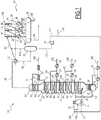
- a first installation 10 according to the invention is illustrated by the figure 1 .
- This installation 10 is intended for the implementation of a first method according to the invention, for the vacuum distillation of a charge 12.
- the installation 10 includes an oven 14 for heating the charge 12 and a depletion fluid, a vacuum distillation column 16, and bottom heat exchangers 18.
- the installation 10 further comprises lateral withdrawals 20, 22, 24, and, respectively associated with each lateral withdrawal 20, 22, 24, of the respective heat exchangers 26, 28 and 30.
- the installation 10 comprises '' other types of vacuum distillation arrangements (number of racking 20, 22, 24 variables, number of packing beds 43 variables, number of packing beds 41 variables).
- the installation 10 includes a downstream heat exchanger 32, a vacuum generation unit 34, and a capacity 36 for condensate recovery.
- the installation 10 comprises in this example an optional downstream separator 38 for recovering the exhausting fluid and a pump 40 for recycling the exhausting fluid.
- the vacuum distillation column 16 has a first packing bed 43 whose role is to provide heat exchange over each racking 20, 22, 24, and whose liquid supply is provided by a first diffuser 44.
- the vacuum distillation column 16 has, below each racking 20, 22, 24, a second packing bed 41, the role of which is to ensure fractionation and the supply of which is ensured by a second liquid diffuser 42.
- the heat exchangers 26 and 28 are heat exchangers making it possible to cool part of the withdrawals 58 and 64.
- the downstream heat exchanger 32 is a water exchanger, supplied with a flow of water at ambient temperature.
- the heat exchangers 30 are air heat exchangers.
- the vacuum generation unit 34 comprises a plurality of steam jet ejectors 45, mounted in series with each other, and for each ejector 45, a downstream water condenser 46. Depending on the desired vacuum level, the number of ejector stages in series may vary.
- the unit 34 comprises three ejectors 45 in series and three condensers 46 interposed between the ejectors 45.
- This charge 12 is for example a charge of liquid hydrocarbons, such as a residual oil charge from an atmospheric distillation.
- the mass flow rate of the load 12 is generally between 100 t / h and 1000 t / h
- the charge 12 comes either directly from the bottom of an atmospheric crude distillation column (generally of the order of 350 ° C) or from a storage tank (at a temperature for example of the order of 80 ° C) after reheating to a temperature of the order of 300 ° C.
- the load 12 is first introduced into the oven 14 to be heated and advantageously vaporized there.
- the temperature of the heated charge 50 at the outlet of the oven 14 is generally between 380 ° C and 420 ° C depending on the desired distillation performance and the TBP cutting point between the vacuum residue 79 and the vacuum distillate 20 (
- TBP comes from “True Boiling Point”, an English term meaning “true boiling point.”
- the cutting points cited represent the distilled fraction of crude oil at the temperatures indicated).
- the partially vaporized charge 50 is then introduced into the vacuum distillation column 16 at a level N1 located in the flash zone above the bottom of the vacuum distillation column 16.
- a flow of exhaustion fluid 52 consisting of hydrocarbons having a weighted average boiling point (mean in English or Tmav) between 150 ° C and 250 ° C ( typically of the order of 200 ° C), is introduced into the oven 14 to be heated and advantageously vaporized there.
- This temperature Tmav is defined in the "Databook on hydrocarbons” written by JB Maxwell under the English expression "mean average boiling point”. The calculation of the temperature Tmav according to the method of JB Maxwell is also detailed in Pierre Wuithier's book “Petroleum - Refining and Chemical Engineering”, Volume 1 .
- a kerosene from an atmospheric crude distillation having an initial TBP cutting point of between 145 ° C and 180 ° C and a final TBP cutting point of between 220 ° C and 250 ° C advantageously constitutes the exhausting fluid.
- the exhaustion fluid 52 is completely vaporized and superheated before it is introduced into the bottom of the column 16. A portion of this exhaustion fluid is injected in liquid form into the radiation beam of the vacuum furnace as acceleration fluid in order to limit film temperatures in the tubes.
- the flow of superheated exhaustion fluid 54 is introduced into the vacuum distillation column 16, at a level N2 situated below the last plate of a depletion zone 56 of the vacuum distillation column 16.
- the flow of heated exhaustion fluid 54 rises through the plates of the exhaustion zone56 located between the levels N1 and N2 and evaporates the lighter fractions of the residue under vacuum.
- the vacuum level at the top of the column is advantageously between 13 mbar and 40 mbar (10 mmHg and 30 mmHg), here substantially around 27 mbar (20 mmHg).
- a first stream 58 of heavy vacuum distillate (“HVGO” or “Heavy Vacuum Gas Oil” in English) is taken laterally at a first racking 20 at a lower level N3 located above the level N1.
- a first fraction 60 of the heavy vacuum distillate stream 58 is reintroduced into the column 16 through the second diffuser 42 associated with the withdrawal 20.
- the rest of the heavy vacuum distillate stream 58 passes through a heat exchanger 26 and a second fraction 62 heavy distillate stream 58 from the heat exchanger 26 is reintroduced into the vacuum distillation column 16, through the first diffuser 44 associated with the withdrawal 20.
- the rest of the stream constitutes the production 180 of heavy vacuum distillate from unity.
- a second stream 64 of optional middle vacuum distillate (“MVGO” or “Medium Vacuum Gas Oil” in English) is sampled at the level of a second racking 22 at an average level N4 situated above the level N3.
- MVGO middle vacuum distillate
- a first fraction 66 of the optional vacuum distillate stream 64 is reintroduced into the vacuum distillation column 16 through the second diffuser 42 associated with the second draw-off 22.
- the rest of the vacuum middle distillate stream 64 passes through a heat exchanger 28.
- An optional second fraction 68 of the middle distillate current under vacuum 64 from the heat exchanger 28 is reintroduced into the vacuum distillation column 16, through the first diffuser 44 of the second racking 22.
- the rest of the current constitutes the production 170 of medium vacuum distillate from the unit.
- a third stream 70 of light vacuum distillate (“LVGO” or “Light Vacuum Gas Oil” in English) is sampled at the level of a third racking 24 at a high level N5 situated above the level N4, in the vicinity of the head of the vacuum distillation column 16.
- a first fraction 72 of the light vacuum distillate stream 70 is reintroduced into the vacuum distillation column 16 through the second diffuser 42 associated with the third withdrawal 24.
- the rest of the stream 70 passes through an air exchanger 30.
- a second fraction 74 of the light vacuum distillate stream 70 from the heat exchanger 30 is reintroduced into the distillation column 16, through the first diffuser 44 of the third racking 24.
- the rest of the stream constitutes the production 160 of light distillate vacuum from the unit.
- a bottom stream 79 is recovered at the bottom of the vacuum distillation column 16 and passes through bottom heat exchangers.
- a head stream 80 is drawn at the head of the column, under the effect of the suction produced by the vacuum generation unit 34.
- the head stream 80 has a pressure equal to the column head operating pressure 16 and has a temperature generally between 60 ° C and 100 ° C.
- the overhead stream 80 is then introduced into the downstream heat exchanger 32, to be partially condensed therein by heat exchange with the water flowing in the downstream heat exchanger 32.
- the overhead stream 80 is thus separated into a gaseous flow of head 82 and a liquid flow from foot 84.
- the overhead gas stream 82 is brought to the vacuum generation unit 34. It is introduced into a first ejector 45 where it is entrained by a flow of driving vapor 150. The mixture thus formed is introduced into the first condenser 46, to form a first condensate 86 and a first gas flow 88.
- the first gas stream 88 is successively introduced into a second ejector 45, then into a second condenser 46, to form a second condensate 90 and a second gas stream 92.
- the second gas stream 92 is then introduced into a third ejector 45, then into a third condenser 46, to form a third gas stream 94 of noncondensable combustible gas and a third condensate 96 available at a pressure slightly higher than atmospheric pressure.
- the condensates 86, 90, 96 are recovered in a tank 36 and are separated into a stream of condensed hydrocarbons 98 and a stream of water to be treated 100.
- the bottom liquid stream 84 contains the majority of the exhaust fluid introduced into the exhaust fluid flow 52 at the bottom of the vacuum distillation column 16. In fact, the boiling temperature of the exhaust fluid 52 is lower than that of the light vacuum distillate stream 70 and is higher than that of water vapor.
- the exhausting fluid is however more easily condensable than water vapor. This allows the column to be operated at low pressure, as described above.
- the bottom liquid flow 84 is introduced into the optional downstream separator 38 in equilibrium with the gas flow 82.
- the fraction of foot 112 contains the majority of the exhaustion fluid. It is pumped into the pump 40 to form a stream 114 for recycling the exhaustion fluid.
- a purge stream 116 is taken from the recycling stream 114 in order to reduce the amount of impurities and to keep a quality of recycle stream 114 constant and the quality of which will be as close as possible to the additional exhaustion stream 118.
- purge current 116 generally represents between 5% by mass and 20% by mass of the bottom fraction 112 introduced into the pump 40.
- the method is implemented without recycling with total purge (the absence of recycle flow being compensated for by an additional supplementary flow 118).
- the rest of the recycling stream 114 is returned to the furnace 14 to form, with a supply stream 118 of exhaustion fluid, the flow 52 of exhaustion fluid.
- the removal of the purge current 116 and the supply provided by the supply current 118 make it possible to renew the exhaustion fluid circulating in the process according to the invention. This guarantees the maintenance of a good quality of distillation, and a good aptitude for the condensation of the exhaustion fluid, by eliminating the lighter fractions possibly accumulated.
- the flow rate of the exhaustion fluid flow 52 introduced into the distillation column 16 can be controlled, by adjusting the respective flow rates of the purge stream 116 and the feed stream 118.
- Table 1 illustrates the results obtained by numerical simulation for the first process according to the invention, within the framework of the treatment of a hydrocarbon charge 12 with a mass flow rate equal to 666.7 t / h resulting from the distillation atmospheric of a “OURAL” type of crude.
- the exhaustion fluid is kerosene from from an atmospheric distillation having a TBP cutting point 145 ° C-230 ° C, a molecular weight of 152 g / mol and a density at 15 ° C of 0.781.
- the temperatures are higher at the top of the column 16, which allows a temperature of the flow 74 higher than in a conventional scheme.
- the viscosity of the flow 74 is then reduced, reducing the size of the first air heat exchanger 30.
- the size of the downstream heat exchanger 32 is reduced because there is no longer any water vapor to condense.
- a portion 119 of the flow of drive fluid 52 is derived in the load 12 before its passage through the oven 14 or during this passage.
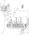
- a second installation 130 according to the invention is illustrated on the figure 2 .
- the second installation 130 is intended for the implementation of a second vacuum distillation process according to the invention.
- downstream heat exchanger 32 of the second installation 130 is disposed directly in the distillation column 16, at the head of the column, above the upper bed 43 associated with the upper withdrawal. 30.
- the downstream heat exchanger 32 is here a plate heat exchanger with low pressure drop (typically less than 7 mbar (5 mmHg), in particular of the order of 1.3 mbar (1 mmHg)).
- the overhead vapors forming the overhead stream 80 from the distillation in the vacuum distillation column 16 penetrate into the heat exchanger 32 within the vacuum distillation column 16 from above.
- the overhead current 80 condenses in the heat exchanger 32.
- a gas flow 82 is extracted from the heat exchanger 32, to be brought to the vacuum generation unit 34 and a bottom liquid flow 84 is recovered at the bottom of the heat exchanger 32, to be brought into the downstream separator 38.
- the table below illustrates the results obtained for the second process according to the invention, within the framework of the treatment of a hydrocarbon charge 12 with a mass flow rate equal to 666.7 t / h, resulting from the atmospheric distillation of a “OURAL” type of rough.
- the exhaustion fluid is kerosene from an atmospheric distillation having a TBP cutting point 145 ° C - 230 ° C, a molecular weight of 152 g / mol and a density at 15 ° C of 0.781.
- the process illustrated in figure 2 has an even lower pressure at the top of the column, for example less than 27 mbar (20 mmHg), and in particular between 13 mbar (10 mmHg) and 20 mbar (15 mmHg).
- this diagram reduces the flow of exhausting fluid 52 necessary, while retaining a reduced heat exchange surface in the downstream heat exchanger 32, and in the exchangers 30.
- the consumption of cooling water is also further reduced, given the lower quantity of exhaustion fluid to be condensed in the heat exchanger 32.
- the exchanger 32 is located outside of the distillation column 16.
- the performances of this variant lie between the performances obtained with the installation shown on the figure 1 and the performance obtained with the installation shown on the figure 2 .
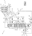
- a third installation 140 according to the invention is illustrated by the figure 3 .
- the installation 140 comprises a second downstream heat exchanger 142 disposed downstream of the first downstream heat exchanger 32 located in the vacuum distillation column 16.
- the second downstream heat exchanger 142 is disposed outside of the vacuum distillation column 16, and receives the gas flow 82 from the first downstream heat exchanger 32.
- the second downstream heat exchanger 142 is a plate heat exchanger with low pressure drop (typically less than 7 mbar (5 mmHg), in particular of the order of 1.3 mbar (1 mmHg)). It is here provided with a boom 143 for spraying a stream of liquid hydrocarbons 144, typically a stream coming from the atmospheric distillation installation.
- the stream of liquid hydrocarbons 144 is for example an atmospheric heavy distillate stream (“HAGO” or “Heavy Atmospheric Gas Oil” in English).
- the third vacuum distillation process according to the invention differs from the second process in that the overhead flow 82 produced in the first downstream heat exchanger 32 is introduced into the second heat exchanger 142.
- the head flow 82 is at least partially condensed on the one hand, thanks to the absorption generated by the introduction of the fluid 144, and on the other hand, by heat exchange with the water.
- An additional condensate 146 is produced at the foot of the second downstream heat exchanger 142, the rest of the gas flow 82 being introduced into the vacuum generation unit 34, as described above.
- the additional condensate is collected in capacity 36.
- the table below illustrates the results obtained for the third process according to the invention, in the context of the treatment of a hydrocarbon charge 12 with a mass flow rate equal to 666.7 t / h resulting from the atmospheric distillation of a "OURAL" type raw.
- the exhaustion fluid is kerosene.
- the third method according to the invention further reduces the steam consumption of the vacuum generation unit 34.
- the overall consumption of fuel in the process is further reduced, as well as the quantity of water to be treated 100 produced.
- the methods according to the invention considerably reduce the consumption of utilities, in particular of cooling water and in water vapor, which reduces the operating costs of the installation, while retaining a process which makes it possible to achieve ambitious performances of recovery rate of distillates under vacuum.
- the flow rate of supply current 118 in exhaustion fluid can be controlled independently of the nature and flow rate of the charge 12, and independently of the flow rate of recycling current 114. The latter making it possible to supply the quantity and the quality of exhaustion fluid 52 necessary for the quality of distillation.
- the ratio between the mass flow rate of the exhausting fluid 52 introduced into the vacuum distillation column 16 and the mass flow rate of the net bottom stream 190 recovered from the bottom of the vacuum distillation column 16 (after derivation of a quenching current returned to the vacuum distillation column 16) is greater than 80 kg of exhaustion fluid per 1000 kg of net bottom current recovered at the bottom of the vacuum distillation column 16 and is in particular between 80 kg and 800 kg of exhaustion fluid for 1000 kg of net bottom current recovered from the bottom of the vacuum distillation column 16.
- the quality of the depletion fluid 52 used consisting of a mixture of hydrocarbons having a weighted average boiling temperature (Tmav) of between 150 ° C and 250 ° C advantageously between 190 ° C and 210 ° C , is perfectly mastered in the process according to the invention.
- Tmav weighted average boiling temperature
- Such a fluid is optimal since it ensures efficient exhaustion of the charge 12, while being easily condensable at very low pressure at the top of the vacuum distillation column 16, and therefore recyclable through the liquid stream 114.
- the fluid 52 has the advantage of being almost completely recovered in the column head stream 80. This allows recycling and avoids the extraction of exhaustion fluid 52 in the distillate streams 160, 170, 180 in particular in stream 160 of light vacuum distillate.
- more than 95% by mass of the exhausting fluid 52 introduced into the vacuum distillation column 16 is recovered from the vacuum distillation column 16 in the stream 112 via the column head stream 80 after condensation.
Claims (13)
- Verfahren zur Destillation einer Kohlenwasserstoffcharge (12) unter Vakuum, die folgenden Schritte umfassend:- Aufheizen der Charge (12);- Einführen der Charge (12) in eine Flashzone (N1) einer Destillationskolonne (16) unter Vakuum;- Entnehmen mindestens eines Destillatstroms (58, 64, 70) an einem Zwischenniveau (N3, N4, N5) der Vakuum-Destillationskolonne (16);- Abziehen eines Kolonnen-Kopfstroms (80) am Kopf der Vakuum-Destillationskolonne (16);- teilweises Kondensieren des Kolonnen-Kopfstroms (80), um einen Flüssigkeitsstrom (84) und einen Gasstrom (82) zu gewinnen;- Überführen des Gasstroms (82) in eine Einheit (34) zur Erzeugung von Vakuum und Gewinnen mindestens eines Kondensats (86, 90, 96) und einer Gasfraktion (94) an nicht kondensierbarem Gas;
wobei das Verfahren das Einführen eines Stroms (52) eines Fluids zum Strippen der Charge (12) in die Vakuum-Destillationskolonne (16) aufweist, dadurch gekennzeichnet, dass das Strippfluid aus einem Kohlenwasserstoffgemisch gebildet wird, das eine mittlere gewichtete Siedetemperatur (Tmav) zwischen 150 °C und 250 °C, vorzugsweise zwischen 190 °C und 210 °C aufweist. - Verfahren nach Anspruch 1, bei dem das Strippfluid aus Kerosin besteht.
- Verfahren nach einem beliebigen der Ansprüche 1 oder 2, das einen Schritt des Bildens eines Rückführstroms (114) des Strippfluids aus dem Flüssigkeitsstrom (84) umfasst.
- Verfahren nach Anspruch 3, das das Entnehmen eines Spülstroms (116) eines Teils der Strippfluids aus dem Rückführstrom (114) des Strippfluids und das Einführen eines Stützstroms (118) an Strippfluid stromabwärts zur Entnahme des Spülstroms (116) umfasst, wobei der Rückführstrom (114) des Strippfluids mindestens einen Teil des Strippfluidstroms (52) bildet.
- Verfahren nach Anspruch 1 oder 2, bei dem das Strippfluid in seiner Gesamtheit aus einem Stützstrom (118) gebildet ist, wobei kein aus dem Flüssigkeitsstrom (84) hervorgegangener Strom in dem Strippfluidstrom (52) recycelt ist, der in die Vakuum-Destillationskolonne (16) eingeführt wird.
- Verfahren nach einem beliebigen der vorhergehenden Ansprüche, das das Einführen des aufgeheizten Strippfluidstroms (54) in die Vakuum-Destillationskolonne (16) an einem Niveau (M2), das unter dem Niveau (N1) des Einführens der Charge (12) liegt, umfasst.
- Verfahren nach Anspruch 6, das das Abzweigen eines Teils (119) des Strippfluidstroms (52) vor seinem Einführen in die Vakuum-Destillationskolonne (16) und seinem Einführen in die Charge (12) umfasst.
- Verfahren nach einem beliebigen der vorhergehenden Ansprüche, bei dem der Schritt des Kondensierens des Kolonnen-Kopfstroms (80) in einem ersten stromabwärts gelegenen Wärmetauscher (32), vorzugsweise einem Plattenwärmetauscher, insbesondere mit geringem Chargenverlust, durchgeführt wird, wobei der erste, stromabwärts gelegene Wärmetauscher (32) in der Vakuum-Destillationskolonne (16) oder außerhalb der Vakuum-Destillationskolonne (16) angeordnet ist.
- Verfahren nach einem beliebigen der vorhergehenden Ansprüche, bei dem der Schritt des Kondensierens des Kolonnen-Kopfstroms (80) in einem ersten stromabwärts gelegenen Wärmetauscher (32), vorzugsweise einem Plattenwärmetauscher, insbesondere mit geringem Chargenverlust, durchgeführt wird, wobei das Verfahren einen Schritt des Überführens des aus dem ersten stromabwärts gelegenen Wärmetauscher (32) stammenden Gasstroms (82) in einen zweiten stromabwärts gelegenen Wärmetauscher (142) umfasst, um ein zusätzliches Kondensat (146) zu erhalten.
- Verfahren nach Anspruch 9, bei dem der Schritt des Überführens des Gasstroms (82) in den zweiten stromabwärts gelegenen Wärmetauscher (142) eine Zerstäubung eines Stroms flüssiger Kohlenwasserstoffe (144) in den Gasstrom (82) aufweist.
- Verfahren nach einem beliebigen der vorhergehenden Ansprüche, das einen Schritt des Rückgewinnens des oder jedes Kondensats (86, 90, 96) in einer Kapazität (36) und die Rückgewinnung eines zu behandelnden Wasserstroms (100) und eines Stroms rückgewonnener Kohlenwasserstoffe (98) in der Kapazität umfasst.
- Verfahren nach einem beliebigen der vorhergehenden Ansprüche, bei dem der Schritt des Überführens des Gasstroms (82) in eine Einheit (34) der Erzeugung des Vakuums das Einführen des Gasstroms in mindestens einen Dampfejektor (45)zum Bilden eines ausgestoßenen Stroms und das teilweise Kondensieren des von jedem Dampfejektor (45) erzeugten ausgestoßenen Stroms in einem Kondensor (46) aufweist.
- Verfahren nach einem beliebigen der vorhergehenden Ansprüche, das die Totalverdampfung und die Überhitzung des Strippfluids (52) vor seiner Einführung in den Boden der Vakuum-Destillationskolonne (16) aufweist.
Applications Claiming Priority (2)
| Application Number | Priority Date | Filing Date | Title |
|---|---|---|---|
| FR1558097A FR3040311B1 (fr) | 2015-09-01 | 2015-09-01 | Procede de distillation sous vide d'une charge d'hydrocarbures et installation associee |
| PCT/EP2016/070614 WO2017037174A1 (fr) | 2015-09-01 | 2016-09-01 | Procédé de distillation sous vide d'une charge d'hydrocarbures et installation associée |
Publications (2)
| Publication Number | Publication Date |
|---|---|
| EP3344732A1 EP3344732A1 (de) | 2018-07-11 |
| EP3344732B1 true EP3344732B1 (de) | 2020-06-17 |
Family
ID=54291529
Family Applications (1)
| Application Number | Title | Priority Date | Filing Date |
|---|---|---|---|
| EP16759779.8A Active EP3344732B1 (de) | 2015-09-01 | 2016-09-01 | Verfahren zur vakuumdestillation von kohlenwasserstoffeinsätzen |
Country Status (5)
| Country | Link |
|---|---|
| US (1) | US20180346824A1 (de) |
| EP (1) | EP3344732B1 (de) |
| ES (1) | ES2816023T3 (de) |
| FR (1) | FR3040311B1 (de) |
| WO (1) | WO2017037174A1 (de) |
Families Citing this family (2)
| Publication number | Priority date | Publication date | Assignee | Title |
|---|---|---|---|---|
| CA3181320C (en) * | 2020-08-07 | 2024-02-13 | Carbovate Development Corp. | Hydrocarbon stream separation system and method |
| US20240026227A1 (en) * | 2022-07-18 | 2024-01-25 | Engineers India Limited | Improved configuration of vacuum distillation unit and process for separating components of reduced crude oil |
Family Cites Families (7)
| Publication number | Priority date | Publication date | Assignee | Title |
|---|---|---|---|---|
| US1843520A (en) * | 1924-05-05 | 1932-02-02 | Standard Oil Co | Art of distilling oils |
| US2853439A (en) * | 1952-08-01 | 1958-09-23 | Exxon Research Engineering Co | Combination distillation and hydrocarbon conversion process |
| US3110663A (en) * | 1959-12-30 | 1963-11-12 | Gulf Oil Corp | Process and apparatus for distilling and visbreaking reduced crude |
| US4261814A (en) * | 1977-11-30 | 1981-04-14 | Exxon Research And Engineering Co. | Vacuum pipestill operation |
| US5167773A (en) * | 1990-01-16 | 1992-12-01 | Exxon Research And Engineering Co. | Distillation tower and sidestream stripper therefor |
| US5858213A (en) * | 1996-07-30 | 1999-01-12 | Exxon Research And Engineering Company | Monitoring for coke formation during hydrocarbon feed processing |
| WO2013107738A1 (en) * | 2012-01-17 | 2013-07-25 | Shell Internationale Research Maatschappij B.V. | Process for vacuum distillation of a crude hydrocarbon stream |
-
2015
- 2015-09-01 FR FR1558097A patent/FR3040311B1/fr not_active Expired - Fee Related
-
2016
- 2016-09-01 US US15/756,374 patent/US20180346824A1/en not_active Abandoned
- 2016-09-01 ES ES16759779T patent/ES2816023T3/es active Active
- 2016-09-01 WO PCT/EP2016/070614 patent/WO2017037174A1/fr unknown
- 2016-09-01 EP EP16759779.8A patent/EP3344732B1/de active Active
Non-Patent Citations (1)
| Title |
|---|
| None * |
Also Published As
| Publication number | Publication date |
|---|---|
| ES2816023T3 (es) | 2021-03-31 |
| WO2017037174A1 (fr) | 2017-03-09 |
| FR3040311B1 (fr) | 2017-10-06 |
| EP3344732A1 (de) | 2018-07-11 |
| FR3040311A1 (fr) | 2017-03-03 |
| US20180346824A1 (en) | 2018-12-06 |
Similar Documents
| Publication | Publication Date | Title |
|---|---|---|
| EP3344732B1 (de) | Verfahren zur vakuumdestillation von kohlenwasserstoffeinsätzen | |
| CA2102718C (en) | Process for the further processing of the vacuum residue in a crude oil refinery | |
| JP2022507701A (ja) | 汚染された廃油を精製する方法および装置 | |
| FR2815966A1 (fr) | Procede de pretraitement, distillation et extraction d'huile usagee | |
| FR2583988A1 (fr) | Procede de distillation avec recuperation d'energie par recompression de vapeur a l'aide d'un ejecteur | |
| EP3643394A1 (de) | Dehydrierungsverfahren eines kohlenwasserstoffgases | |
| EP3679999B1 (de) | Verfahren und anlage zur behandlung einer flüssigkeit | |
| US6337011B1 (en) | Pour point depression unit using mild thermal cracker | |
| FR3025523A1 (fr) | Procede de distillation de goudron de houille et dispositif permettant sa mise en oeuvre | |
| FR2768154A1 (fr) | Procede et installation de vapocraquage d'hydrocarbures a charge flexible | |
| US8784648B2 (en) | Method for producing vacuum in a vacuum oil-stock distillation column and a plant for carrying out the method | |
| WO2024019638A1 (ru) | Способ вакуумной перегонки углеводородных остатков и тяжелых фракций | |
| RU2792370C1 (ru) | Способ вакуумной перегонки углеводородных остатков и тяжелых фракций | |
| EP4105296B1 (de) | Verfahren zur behandlung eines gasstroms aus kunststoff-pyrolyse und/oder biomasse-pyrolyse und anlage zur integration in einen steam cracker | |
| CN114225452A (zh) | 一种废润滑油四段蒸发回收方法 | |
| FR2609722A1 (fr) | Installation pour le soutirage d'un melange d'alcool et d'eau a partir d'un mout contenant de l'alcool | |
| BE393050A (de) | ||
| JP6269465B2 (ja) | 余剰安水の処理方法 | |
| BE363523A (de) | ||
| BE495837A (de) | ||
| LU82410A1 (fr) | Installation pour la purification de produits petroliers et derives souilles par des liquides etrangers | |
| BE350030A (de) | ||
| BE352854A (de) | ||
| JP2011052171A (ja) | コークス炉ガスからの軽油の回収方法 | |
| BE359594A (de) |
Legal Events
| Date | Code | Title | Description |
|---|---|---|---|
| STAA | Information on the status of an ep patent application or granted ep patent |
Free format text: STATUS: UNKNOWN |
|
| STAA | Information on the status of an ep patent application or granted ep patent |
Free format text: STATUS: THE INTERNATIONAL PUBLICATION HAS BEEN MADE |
|
| PUAI | Public reference made under article 153(3) epc to a published international application that has entered the european phase |
Free format text: ORIGINAL CODE: 0009012 |
|
| STAA | Information on the status of an ep patent application or granted ep patent |
Free format text: STATUS: REQUEST FOR EXAMINATION WAS MADE |
|
| 17P | Request for examination filed |
Effective date: 20180228 |
|
| AK | Designated contracting states |
Kind code of ref document: A1 Designated state(s): AL AT BE BG CH CY CZ DE DK EE ES FI FR GB GR HR HU IE IS IT LI LT LU LV MC MK MT NL NO PL PT RO RS SE SI SK SM TR |
|
| AX | Request for extension of the european patent |
Extension state: BA ME |
|
| DAV | Request for validation of the european patent (deleted) | ||
| DAX | Request for extension of the european patent (deleted) | ||
| STAA | Information on the status of an ep patent application or granted ep patent |
Free format text: STATUS: EXAMINATION IS IN PROGRESS |
|
| 17Q | First examination report despatched |
Effective date: 20181214 |
|
| GRAP | Despatch of communication of intention to grant a patent |
Free format text: ORIGINAL CODE: EPIDOSNIGR1 |
|
| STAA | Information on the status of an ep patent application or granted ep patent |
Free format text: STATUS: GRANT OF PATENT IS INTENDED |
|
| INTG | Intention to grant announced |
Effective date: 20200219 |
|
| GRAS | Grant fee paid |
Free format text: ORIGINAL CODE: EPIDOSNIGR3 |
|
| GRAA | (expected) grant |
Free format text: ORIGINAL CODE: 0009210 |
|
| STAA | Information on the status of an ep patent application or granted ep patent |
Free format text: STATUS: THE PATENT HAS BEEN GRANTED |
|
| AK | Designated contracting states |
Kind code of ref document: B1 Designated state(s): AL AT BE BG CH CY CZ DE DK EE ES FI FR GB GR HR HU IE IS IT LI LT LU LV MC MK MT NL NO PL PT RO RS SE SI SK SM TR |
|
| REG | Reference to a national code |
Ref country code: GB Ref legal event code: FG4D Free format text: NOT ENGLISH |
|
| REG | Reference to a national code |
Ref country code: CH Ref legal event code: EP |
|
| REG | Reference to a national code |
Ref country code: IE Ref legal event code: FG4D Free format text: LANGUAGE OF EP DOCUMENT: FRENCH |
|
| REG | Reference to a national code |
Ref country code: DE Ref legal event code: R096 Ref document number: 602016038285 Country of ref document: DE |
|
| REG | Reference to a national code |
Ref country code: AT Ref legal event code: REF Ref document number: 1281310 Country of ref document: AT Kind code of ref document: T Effective date: 20200715 |
|
| REG | Reference to a national code |
Ref country code: NL Ref legal event code: FP |
|
| REG | Reference to a national code |
Ref country code: FI Ref legal event code: FGE |
|
| PG25 | Lapsed in a contracting state [announced via postgrant information from national office to epo] |
Ref country code: LT Free format text: LAPSE BECAUSE OF FAILURE TO SUBMIT A TRANSLATION OF THE DESCRIPTION OR TO PAY THE FEE WITHIN THE PRESCRIBED TIME-LIMIT Effective date: 20200617 Ref country code: GR Free format text: LAPSE BECAUSE OF FAILURE TO SUBMIT A TRANSLATION OF THE DESCRIPTION OR TO PAY THE FEE WITHIN THE PRESCRIBED TIME-LIMIT Effective date: 20200918 Ref country code: NO Free format text: LAPSE BECAUSE OF FAILURE TO SUBMIT A TRANSLATION OF THE DESCRIPTION OR TO PAY THE FEE WITHIN THE PRESCRIBED TIME-LIMIT Effective date: 20200917 Ref country code: SE Free format text: LAPSE BECAUSE OF FAILURE TO SUBMIT A TRANSLATION OF THE DESCRIPTION OR TO PAY THE FEE WITHIN THE PRESCRIBED TIME-LIMIT Effective date: 20200617 |
|
| REG | Reference to a national code |
Ref country code: LT Ref legal event code: MG4D |
|
| PG25 | Lapsed in a contracting state [announced via postgrant information from national office to epo] |
Ref country code: LV Free format text: LAPSE BECAUSE OF FAILURE TO SUBMIT A TRANSLATION OF THE DESCRIPTION OR TO PAY THE FEE WITHIN THE PRESCRIBED TIME-LIMIT Effective date: 20200617 Ref country code: RS Free format text: LAPSE BECAUSE OF FAILURE TO SUBMIT A TRANSLATION OF THE DESCRIPTION OR TO PAY THE FEE WITHIN THE PRESCRIBED TIME-LIMIT Effective date: 20200617 Ref country code: HR Free format text: LAPSE BECAUSE OF FAILURE TO SUBMIT A TRANSLATION OF THE DESCRIPTION OR TO PAY THE FEE WITHIN THE PRESCRIBED TIME-LIMIT Effective date: 20200617 Ref country code: BG Free format text: LAPSE BECAUSE OF FAILURE TO SUBMIT A TRANSLATION OF THE DESCRIPTION OR TO PAY THE FEE WITHIN THE PRESCRIBED TIME-LIMIT Effective date: 20200917 |
|
| PG25 | Lapsed in a contracting state [announced via postgrant information from national office to epo] |
Ref country code: AL Free format text: LAPSE BECAUSE OF FAILURE TO SUBMIT A TRANSLATION OF THE DESCRIPTION OR TO PAY THE FEE WITHIN THE PRESCRIBED TIME-LIMIT Effective date: 20200617 |
|
| PG25 | Lapsed in a contracting state [announced via postgrant information from national office to epo] |
Ref country code: PT Free format text: LAPSE BECAUSE OF FAILURE TO SUBMIT A TRANSLATION OF THE DESCRIPTION OR TO PAY THE FEE WITHIN THE PRESCRIBED TIME-LIMIT Effective date: 20201019 Ref country code: RO Free format text: LAPSE BECAUSE OF FAILURE TO SUBMIT A TRANSLATION OF THE DESCRIPTION OR TO PAY THE FEE WITHIN THE PRESCRIBED TIME-LIMIT Effective date: 20200617 Ref country code: SM Free format text: LAPSE BECAUSE OF FAILURE TO SUBMIT A TRANSLATION OF THE DESCRIPTION OR TO PAY THE FEE WITHIN THE PRESCRIBED TIME-LIMIT Effective date: 20200617 Ref country code: EE Free format text: LAPSE BECAUSE OF FAILURE TO SUBMIT A TRANSLATION OF THE DESCRIPTION OR TO PAY THE FEE WITHIN THE PRESCRIBED TIME-LIMIT Effective date: 20200617 |
|
| PG25 | Lapsed in a contracting state [announced via postgrant information from national office to epo] |
Ref country code: SK Free format text: LAPSE BECAUSE OF FAILURE TO SUBMIT A TRANSLATION OF THE DESCRIPTION OR TO PAY THE FEE WITHIN THE PRESCRIBED TIME-LIMIT Effective date: 20200617 Ref country code: PL Free format text: LAPSE BECAUSE OF FAILURE TO SUBMIT A TRANSLATION OF THE DESCRIPTION OR TO PAY THE FEE WITHIN THE PRESCRIBED TIME-LIMIT Effective date: 20200617 Ref country code: IS Free format text: LAPSE BECAUSE OF FAILURE TO SUBMIT A TRANSLATION OF THE DESCRIPTION OR TO PAY THE FEE WITHIN THE PRESCRIBED TIME-LIMIT Effective date: 20201017 |
|
| REG | Reference to a national code |
Ref country code: DE Ref legal event code: R097 Ref document number: 602016038285 Country of ref document: DE |
|
| REG | Reference to a national code |
Ref country code: ES Ref legal event code: FG2A Ref document number: 2816023 Country of ref document: ES Kind code of ref document: T3 Effective date: 20210331 |
|
| PLBE | No opposition filed within time limit |
Free format text: ORIGINAL CODE: 0009261 |
|
| STAA | Information on the status of an ep patent application or granted ep patent |
Free format text: STATUS: NO OPPOSITION FILED WITHIN TIME LIMIT |
|
| PG25 | Lapsed in a contracting state [announced via postgrant information from national office to epo] |
Ref country code: DK Free format text: LAPSE BECAUSE OF FAILURE TO SUBMIT A TRANSLATION OF THE DESCRIPTION OR TO PAY THE FEE WITHIN THE PRESCRIBED TIME-LIMIT Effective date: 20200617 |
|
| REG | Reference to a national code |
Ref country code: CH Ref legal event code: PL |
|
| REG | Reference to a national code |
Ref country code: AT Ref legal event code: UEP Ref document number: 1281310 Country of ref document: AT Kind code of ref document: T Effective date: 20200617 |
|
| 26N | No opposition filed |
Effective date: 20210318 |
|
| PG25 | Lapsed in a contracting state [announced via postgrant information from national office to epo] |
Ref country code: SI Free format text: LAPSE BECAUSE OF FAILURE TO SUBMIT A TRANSLATION OF THE DESCRIPTION OR TO PAY THE FEE WITHIN THE PRESCRIBED TIME-LIMIT Effective date: 20200617 |
|
| REG | Reference to a national code |
Ref country code: BE Ref legal event code: MM Effective date: 20200930 |
|
| PG25 | Lapsed in a contracting state [announced via postgrant information from national office to epo] |
Ref country code: LU Free format text: LAPSE BECAUSE OF NON-PAYMENT OF DUE FEES Effective date: 20200901 |
|
| PG25 | Lapsed in a contracting state [announced via postgrant information from national office to epo] |
Ref country code: BE Free format text: LAPSE BECAUSE OF NON-PAYMENT OF DUE FEES Effective date: 20200930 Ref country code: CH Free format text: LAPSE BECAUSE OF NON-PAYMENT OF DUE FEES Effective date: 20200930 Ref country code: IE Free format text: LAPSE BECAUSE OF NON-PAYMENT OF DUE FEES Effective date: 20200901 Ref country code: LI Free format text: LAPSE BECAUSE OF NON-PAYMENT OF DUE FEES Effective date: 20200930 |
|
| PG25 | Lapsed in a contracting state [announced via postgrant information from national office to epo] |
Ref country code: TR Free format text: LAPSE BECAUSE OF FAILURE TO SUBMIT A TRANSLATION OF THE DESCRIPTION OR TO PAY THE FEE WITHIN THE PRESCRIBED TIME-LIMIT Effective date: 20200617 Ref country code: MT Free format text: LAPSE BECAUSE OF FAILURE TO SUBMIT A TRANSLATION OF THE DESCRIPTION OR TO PAY THE FEE WITHIN THE PRESCRIBED TIME-LIMIT Effective date: 20200617 Ref country code: CY Free format text: LAPSE BECAUSE OF FAILURE TO SUBMIT A TRANSLATION OF THE DESCRIPTION OR TO PAY THE FEE WITHIN THE PRESCRIBED TIME-LIMIT Effective date: 20200617 |
|
| PG25 | Lapsed in a contracting state [announced via postgrant information from national office to epo] |
Ref country code: MK Free format text: LAPSE BECAUSE OF FAILURE TO SUBMIT A TRANSLATION OF THE DESCRIPTION OR TO PAY THE FEE WITHIN THE PRESCRIBED TIME-LIMIT Effective date: 20200617 Ref country code: MC Free format text: LAPSE BECAUSE OF FAILURE TO SUBMIT A TRANSLATION OF THE DESCRIPTION OR TO PAY THE FEE WITHIN THE PRESCRIBED TIME-LIMIT Effective date: 20200617 |
|
| P01 | Opt-out of the competence of the unified patent court (upc) registered |
Effective date: 20230601 |
|
| PGFP | Annual fee paid to national office [announced via postgrant information from national office to epo] |
Ref country code: NL Payment date: 20230825 Year of fee payment: 8 |
|
| PGFP | Annual fee paid to national office [announced via postgrant information from national office to epo] |
Ref country code: IT Payment date: 20230829 Year of fee payment: 8 Ref country code: GB Payment date: 20230817 Year of fee payment: 8 Ref country code: FI Payment date: 20230912 Year of fee payment: 8 Ref country code: CZ Payment date: 20230831 Year of fee payment: 8 Ref country code: AT Payment date: 20230825 Year of fee payment: 8 |
|
| PGFP | Annual fee paid to national office [announced via postgrant information from national office to epo] |
Ref country code: FR Payment date: 20230821 Year of fee payment: 8 Ref country code: DE Payment date: 20230822 Year of fee payment: 8 |
|
| PGFP | Annual fee paid to national office [announced via postgrant information from national office to epo] |
Ref country code: ES Payment date: 20231006 Year of fee payment: 8 |