EP3344363B1 - Painting booth with automatic filter system - Google Patents
Painting booth with automatic filter system Download PDFInfo
- Publication number
- EP3344363B1 EP3344363B1 EP16779182.1A EP16779182A EP3344363B1 EP 3344363 B1 EP3344363 B1 EP 3344363B1 EP 16779182 A EP16779182 A EP 16779182A EP 3344363 B1 EP3344363 B1 EP 3344363B1
- Authority
- EP
- European Patent Office
- Prior art keywords
- filter
- housing
- booth
- paint
- shuttle
- Prior art date
- Legal status (The legal status is an assumption and is not a legal conclusion. Google has not performed a legal analysis and makes no representation as to the accuracy of the status listed.)
- Active
Links
- 238000010422 painting Methods 0.000 title 1
- 238000005507 spraying Methods 0.000 claims description 16
- 238000012546 transfer Methods 0.000 claims description 16
- 239000003973 paint Substances 0.000 claims description 7
- 238000001914 filtration Methods 0.000 claims description 4
- 238000005192 partition Methods 0.000 claims description 4
- 238000000926 separation method Methods 0.000 claims 1
- 238000000034 method Methods 0.000 description 5
- 238000002485 combustion reaction Methods 0.000 description 2
- 238000000605 extraction Methods 0.000 description 2
- 239000007921 spray Substances 0.000 description 2
- 238000004891 communication Methods 0.000 description 1
- 238000007599 discharging Methods 0.000 description 1
- 238000006073 displacement reaction Methods 0.000 description 1
- 230000008030 elimination Effects 0.000 description 1
- 238000003379 elimination reaction Methods 0.000 description 1
- 239000000446 fuel Substances 0.000 description 1
- 239000003517 fume Substances 0.000 description 1
- 238000003780 insertion Methods 0.000 description 1
- 230000037431 insertion Effects 0.000 description 1
- 238000012423 maintenance Methods 0.000 description 1
- 239000000463 material Substances 0.000 description 1
- 238000011084 recovery Methods 0.000 description 1
- 238000004064 recycling Methods 0.000 description 1
- 238000007789 sealing Methods 0.000 description 1
- 230000032258 transport Effects 0.000 description 1
Images
Classifications
-
- B—PERFORMING OPERATIONS; TRANSPORTING
- B05—SPRAYING OR ATOMISING IN GENERAL; APPLYING FLUENT MATERIALS TO SURFACES, IN GENERAL
- B05B—SPRAYING APPARATUS; ATOMISING APPARATUS; NOZZLES
- B05B14/00—Arrangements for collecting, re-using or eliminating excess spraying material
- B05B14/40—Arrangements for collecting, re-using or eliminating excess spraying material for use in spray booths
- B05B14/43—Arrangements for collecting, re-using or eliminating excess spraying material for use in spray booths by filtering the air charged with excess material
-
- B—PERFORMING OPERATIONS; TRANSPORTING
- B01—PHYSICAL OR CHEMICAL PROCESSES OR APPARATUS IN GENERAL
- B01D—SEPARATION
- B01D46/00—Filters or filtering processes specially modified for separating dispersed particles from gases or vapours
- B01D46/0002—Casings; Housings; Frame constructions
- B01D46/0005—Mounting of filtering elements within casings, housings or frames
- B01D46/0006—Filter elements or cartridges installed in a drawer-like manner
-
- B—PERFORMING OPERATIONS; TRANSPORTING
- B05—SPRAYING OR ATOMISING IN GENERAL; APPLYING FLUENT MATERIALS TO SURFACES, IN GENERAL
- B05B—SPRAYING APPARATUS; ATOMISING APPARATUS; NOZZLES
- B05B16/00—Spray booths
- B05B16/60—Ventilation arrangements specially adapted therefor
-
- B—PERFORMING OPERATIONS; TRANSPORTING
- B01—PHYSICAL OR CHEMICAL PROCESSES OR APPARATUS IN GENERAL
- B01D—SEPARATION
- B01D46/00—Filters or filtering processes specially modified for separating dispersed particles from gases or vapours
- B01D46/0002—Casings; Housings; Frame constructions
-
- B—PERFORMING OPERATIONS; TRANSPORTING
- B05—SPRAYING OR ATOMISING IN GENERAL; APPLYING FLUENT MATERIALS TO SURFACES, IN GENERAL
- B05B—SPRAYING APPARATUS; ATOMISING APPARATUS; NOZZLES
- B05B16/00—Spray booths
- B05B16/90—Spray booths comprising conveying means for moving objects or other work to be sprayed in and out of the booth, e.g. through the booth
-
- Y—GENERAL TAGGING OF NEW TECHNOLOGICAL DEVELOPMENTS; GENERAL TAGGING OF CROSS-SECTIONAL TECHNOLOGIES SPANNING OVER SEVERAL SECTIONS OF THE IPC; TECHNICAL SUBJECTS COVERED BY FORMER USPC CROSS-REFERENCE ART COLLECTIONS [XRACs] AND DIGESTS
- Y02—TECHNOLOGIES OR APPLICATIONS FOR MITIGATION OR ADAPTATION AGAINST CLIMATE CHANGE
- Y02P—CLIMATE CHANGE MITIGATION TECHNOLOGIES IN THE PRODUCTION OR PROCESSING OF GOODS
- Y02P70/00—Climate change mitigation technologies in the production process for final industrial or consumer products
- Y02P70/10—Greenhouse gas [GHG] capture, material saving, heat recovery or other energy efficient measures, e.g. motor control, characterised by manufacturing processes, e.g. for rolling metal or metal working
Definitions
- the present invention relates to a paint-spraying booth provided with an automated system for changing the filters for eliminating the overspray.
- the paint-spraying booths are provided with an air flow which passes through the working zone so as to convey the overspray, namely the nebulized excess paint, outside of the booth.
- the air drawn in with the overspray must be necessarily purified of the paint before it can be released into the environment or reintroduced into the booth and for this reason the air flow is made to pass through suitable filtering systems.
- the general object of the present invention is to provide a booth with a filtering system having means for automated replacement of the overspray elimination filters.
- Figure 1 shows a paint-spraying booth according to the invention, denoted generally by 10.
- the booth comprises a chamber 11 for spraying objects 12 (for example motor vehicle bodies).
- objects 12 for example motor vehicle bodies.
- the objects to be sprayed are advantageously transported into the chamber 11 by means of a known sequential conveyor system 13.
- the chamber 11 is provided with known paint-spraying devices (not shown) which are operated so as to spray the paint onto the surfaces of the object to be painted.
- the paint-spraying devices may be realized in the form of known robot arms provided with spray guns.
- Air for removal of the overspray from the chamber 11 is circulated inside the booth.
- suitable air circulation fans (not shown) are advantageously provided according to a technique known per se for producing a continuous flow of air through the chamber.
- the floor 14 of the chamber 11 is composed of grilles through which the chamber air is drawn.
- the ceiling of the chamber is therefore provided with corresponding air inlets 15 so as to have a continuous air flow which passes vertically through the chamber from the top downwards during the paint-spraying operations.
- the air flow leaving the chamber 11 is conveyed to at least one filter unit 16 which retains the overspray.
- the filter unit comprises advantageously a plurality of replaceable filter modules 17, each accommodated inside an associated housing 18 which forms a seat for the filter module and which connects it between the inlet for the air from the chamber and the outlet for discharging the air after filtering.
- a first passage 21 for entry of the air into the filters and a second passage 24 where the air exits from the filters are provided, with the filter modules of the filter unit being connected in parallel between the entry and exit passages.
- the filter units are advantageously two in number, being arranged facing each other in a mirror-image layout relative to a vertical mid-plane of the booth.
- this plane is parallel to the direction of movement of the transportation system 13 which defines the direction of longitudinal extension of the booth.
- the filter unit or units 16 are preferably arranged directly underneath the floor 14.
- a chamber 19 having a cross-section generally in the form of a T for defining an upper header 20 extending horizontally underneath the floor 14 for receiving air therefrom and with the vertical part of the T which forms the passage 21 extending along the filter modules for allowing entry of the air into the filters.
- the inlets 22 of the filter modules present in the respective housings 18 are arranged alongside each other.
- the outlets 23 of the filter modules in the respective housings 18 communicate in turn with the passage 24 for evacuation of the filtered air flow.
- the filter modules have advantageously a parallelepiped form with inlet and outlet arranged on opposite sides and connected in parallel between the inlet passage 21 and the outlet passage 24.
- the filters may be of various suitable types, for example also of the disposable type made of cardboard.
- the passage 24 is advantageously connected (preferably via one or more further filters 26, for example of the "pocket” type) to a duct 27 for evacuating the air from the booth.
- the duct 27 may definitively evacuate the air externally and/or convey it back into the chamber 11 for recycling of purified air.
- controlled gates 28 may be provided for throttling and/or closing the air flow leaving the filter modules. These gates (as well as the optional further filters 26) may be provided one for each filter module 17 or may be provided for several filter modules 17.
- the booth according to the invention comprises at least one automated system 30 for removing and transporting each filter module 17 of the plurality between its housing 18 and a zone 31 for entry/exit of the filter modules into/from the booth, for removing a filter module from its housing and transporting it into the entry/exit zone and for removing a filter module from the entry/exit zone and transporting it into an empty housing 18.
- the automated system comprises advantageously means which are movable sequentially between the plurality of housings 18 of the filter modules 17 and the zone 31 for entry/exit of the filter modules into/from the booth.
- these means may comprise a shuttle 32 which travels hung from the rails 33 which extend along the corridor 24 so as to pass sequentially in front of the housings 18 of the filter modules.
- the shuttle may be moved by means of a motorized-chain system 41.
- Further transfer means 34 may be provided for transferring each module between its housing and the shuttle.
- these means 34 may comprise for each module a carriage 43 from which the module is hung and which may be transferred on the shuttle 32 by means of a suitable actuator or transfer device 35, thus extracting the filter module from its housing and transferring it inside the passage 24.
- the shuttle Once the shuttle has loaded the filter module it may be displaced towards the entry/exit zone 31 where the used filter is unloaded from the shuttle and removed from the booth. Similarly, a new filter may be loaded onto the shuttle in the entry/exit zone 31 and transported and inserted into an empty housing 18, with a procedure which is the reverse of that described above for extraction.
- the modules may also be moved from and to the entry/exit zone for example by means of a suitable known elevator 42 which picks them up from a store or from a manual loading/unloading zone.
- a suitable known elevator 42 which picks them up from a store or from a manual loading/unloading zone.
- the entry/exit zone may also comprise a suitable compactor device, of the type known per se.
- the filter modules have advantageously the inlet side which sealingly adheres with its edge against a circumferential edge 36 of the communication opening 25 between housing 18 and entry passage 21. In this way, it is sufficient to rest the filter against the edge 36 in order to ensure the air tightness and the circulation through the filter of the air flow from the paint-spraying chamber.
- the sealing contact may be for example ensured by the actuator or transfer device 35 which pushes the filter module inside its housing. Further known automated constraining means may be provided for keeping the module in the operative position. Means are also provided for closing the opening 25 for entry of the air into the filter modules.
- the entry passage 21 is provided with a movable partition 37 which is motorized (using means known per se and therefore not shown, for example a chain drive system) so as to travel along the passage and close in sequence one of the openings for entry into the filter modules.
- a movable partition 37 which is motorized (using means known per se and therefore not shown, for example a chain drive system) so as to travel along the passage and close in sequence one of the openings for entry into the filter modules.
- the partition is displaced so as to close the entrance to this module and the module is then extracted from the housing and transferred onto the shuttle which transports it to the exit zone.
- the partition 37 may return into the rest position (shown in Figure 2c for the left-hand unit).
- a transfer chamber 38 provided with a first door 39 communicating with the passage 24 and a second door 40 communicating with the outside, and in particular the entry/exit zone 31, are provided.
- the transfer chamber 38 may also be used to house the shuttle 32 when not in use, closing both the doors 39 and 40 so as to keep it isolated from the air flow present inside the passage 24.
- Figure 3 shows in greater detail a possible advantageous embodiment of the system 30 for transportation and replacement of the filters.
- each filter module 17 is hung from an associated carriage 43 which is displaceable along rails 44 arranged on the ceiling of each housing 18 and extending in the direction of extraction/insertion of the module from/into the housing.
- this direction is transverse to the direction of displacement of the shuttle 32 on its rails 33.
- the shuttle 32 comprises in turn rail sections 45 which are aligned with the rails 44 of a housing when the shuttle is transported into the vicinity of this housing.
- the actuator 35 may displace the filter unit with the carriage 43 from the rails 43 to the rails 45 and vice versa.
- the actuator 35 may be a known linear actuator provided with a motorized slider 46 which engages a suitable operating end 47 of the carriage 43 so as to controllably displace it between housing 18 and shuttle 32.
- Other transfer devices may be imagined by the persons skilled in the art.
- Each filter unit comprises advantageously an associated movement system in a mirror-image arrangement relative to the other one.
- the entry/exit zone may be divided into an entry zone where the new filters arrive and an exit zone where the used filters are transferred.
- Changing of the filters may be performed by means of a manual change command entered by the operator or by means of a cyclical procedure whereby a filter is changed after a certain operating time. Suitable sensors may be provided, these requesting automatic changing of a filter when it is detected that it is clogged up by more than a certain amount.
- the filter modules may also be sequentially replaced one at a time (or in pairs, in the case of two filter units with associated independent automated systems), until all the filter modules have been completely replaced, without stopping the plant.
Description
- The present invention relates to a paint-spraying booth provided with an automated system for changing the filters for eliminating the overspray.
- Usually the paint-spraying booths are provided with an air flow which passes through the working zone so as to convey the overspray, namely the nebulized excess paint, outside of the booth. The air drawn in with the overspray must be necessarily purified of the paint before it can be released into the environment or reintroduced into the booth and for this reason the air flow is made to pass through suitable filtering systems.
- The systems which use filters become clogged as they get filled with paint and must be regularly replaced. This often results in the booth being non-operative for a considerable period of time. Moreover, the filter changing operations may be complex and difficult for the maintenance personnel who are often obliged to work in "contaminated" zones.
- The general object of the present invention is to provide a booth with a filtering system having means for automated replacement of the overspray elimination filters.
- In view of this object, the idea which has occurred, according to invention, is to provide a paint-spraying booth according to claim 1.
- In order to illustrate more clearly the innovative principles of the present invention and its advantages compared to the prior art, see for example
DE202014103177U1 , an example of embodiment applying these principles will be described below with the aid of the accompanying drawings. In the drawings: -
Figure 1 shows a partially sectioned schematic elevation view of a booth according to the invention; -
Figure 2 shows a schematic plan view of the booth sectioned along the line II-II ofFigure 1 ; -
Figure 3 shows an enlarged, partial, schematic view of an automated system for transporting the filters into the booth according to the invention; -
Figure 4 shows a schematic view similar to that ofFigure 1 and showing a possible variation of embodiment of a booth according to the invention. - With reference to the figures,
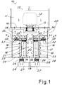
Figure 1 shows a paint-spraying booth according to the invention, denoted generally by 10. - The booth comprises a
chamber 11 for spraying objects 12 (for example motor vehicle bodies). The objects to be sprayed are advantageously transported into thechamber 11 by means of a knownsequential conveyor system 13. - The
chamber 11 is provided with known paint-spraying devices (not shown) which are operated so as to spray the paint onto the surfaces of the object to be painted. Advantageously, the paint-spraying devices may be realized in the form of known robot arms provided with spray guns. - Air for removal of the overspray from the
chamber 11 is circulated inside the booth. For example, suitable air circulation fans (not shown) are advantageously provided according to a technique known per se for producing a continuous flow of air through the chamber. Advantageously, for circulation of the air flow, thefloor 14 of thechamber 11 is composed of grilles through which the chamber air is drawn. The ceiling of the chamber is therefore provided withcorresponding air inlets 15 so as to have a continuous air flow which passes vertically through the chamber from the top downwards during the paint-spraying operations. The air flow leaving thechamber 11 is conveyed to at least onefilter unit 16 which retains the overspray. The filter unit comprises advantageously a plurality ofreplaceable filter modules 17, each accommodated inside an associatedhousing 18 which forms a seat for the filter module and which connects it between the inlet for the air from the chamber and the outlet for discharging the air after filtering. - In particular, advantageously a
first passage 21 for entry of the air into the filters and asecond passage 24 where the air exits from the filters are provided, with the filter modules of the filter unit being connected in parallel between the entry and exit passages. - In the embodiment shown in
Figure 1 , the filter units are advantageously two in number, being arranged facing each other in a mirror-image layout relative to a vertical mid-plane of the booth. Advantageously this plane is parallel to the direction of movement of thetransportation system 13 which defines the direction of longitudinal extension of the booth. - In the booth embodiment where the air is drawn through the
floor 14, the filter unit orunits 16 are preferably arranged directly underneath thefloor 14. - In the embodiment shown there is advantageously a
chamber 19 having a cross-section generally in the form of a T for defining anupper header 20 extending horizontally underneath thefloor 14 for receiving air therefrom and with the vertical part of the T which forms thepassage 21 extending along the filter modules for allowing entry of the air into the filters. Inside thepassage 21 theinlets 22 of the filter modules present in therespective housings 18 are arranged alongside each other. - The
outlets 23 of the filter modules in therespective housings 18 communicate in turn with thepassage 24 for evacuation of the filtered air flow. In the embodiment shown, the filter modules have advantageously a parallelepiped form with inlet and outlet arranged on opposite sides and connected in parallel between theinlet passage 21 and theoutlet passage 24. The filters may be of various suitable types, for example also of the disposable type made of cardboard. - The
passage 24 is advantageously connected (preferably via one or morefurther filters 26, for example of the "pocket" type) to aduct 27 for evacuating the air from the booth. Theduct 27 may definitively evacuate the air externally and/or convey it back into thechamber 11 for recycling of purified air. - Again advantageously, controlled
gates 28 may be provided for throttling and/or closing the air flow leaving the filter modules. These gates (as well as the optional further filters 26) may be provided one for eachfilter module 17 or may be provided forseveral filter modules 17. - In
Figure 1 , the air flow into the booth is indicated schematically by means of the arrows. - As can be clearly seen also in
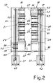
Figure 2 , the booth according to the invention comprises at least oneautomated system 30 for removing and transporting eachfilter module 17 of the plurality between itshousing 18 and azone 31 for entry/exit of the filter modules into/from the booth, for removing a filter module from its housing and transporting it into the entry/exit zone and for removing a filter module from the entry/exit zone and transporting it into anempty housing 18. - The automated system comprises advantageously means which are movable sequentially between the plurality of
housings 18 of thefilter modules 17 and thezone 31 for entry/exit of the filter modules into/from the booth. Preferably, as can be clearly seen in the figures, these means may comprise ashuttle 32 which travels hung from therails 33 which extend along thecorridor 24 so as to pass sequentially in front of thehousings 18 of the filter modules. The shuttle may be moved by means of a motorized-chain system 41. - Further transfer means 34 may be provided for transferring each module between its housing and the shuttle. In particular, as can be clearly seen in
Figure 3 , these means 34 may comprise for each module acarriage 43 from which the module is hung and which may be transferred on theshuttle 32 by means of a suitable actuator ortransfer device 35, thus extracting the filter module from its housing and transferring it inside thepassage 24. - Once the shuttle has loaded the filter module it may be displaced towards the entry/
exit zone 31 where the used filter is unloaded from the shuttle and removed from the booth. Similarly, a new filter may be loaded onto the shuttle in the entry/exit zone 31 and transported and inserted into anempty housing 18, with a procedure which is the reverse of that described above for extraction. - The modules may also be moved from and to the entry/exit zone for example by means of a suitable known
elevator 42 which picks them up from a store or from a manual loading/unloading zone. Advantageously, in the case of compatible filters, for example made of cardboard, the entry/exit zone may also comprise a suitable compactor device, of the type known per se. - The filter modules have advantageously the inlet side which sealingly adheres with its edge against a
circumferential edge 36 of the communication opening 25 betweenhousing 18 andentry passage 21. In this way, it is sufficient to rest the filter against theedge 36 in order to ensure the air tightness and the circulation through the filter of the air flow from the paint-spraying chamber. The sealing contact may be for example ensured by the actuator ortransfer device 35 which pushes the filter module inside its housing. Further known automated constraining means may be provided for keeping the module in the operative position. Means are also provided for closing theopening 25 for entry of the air into the filter modules. Advantageously, in order to realize these means, theentry passage 21 is provided with amovable partition 37 which is motorized (using means known per se and therefore not shown, for example a chain drive system) so as to travel along the passage and close in sequence one of the openings for entry into the filter modules. In this way, when it is required to replace a filter module the partition is displaced so as to close the entrance to this module and the module is then extracted from the housing and transferred onto the shuttle which transports it to the exit zone. Once a new filter module has been introduced into the housing, thepartition 37 may return into the rest position (shown inFigure 2c for the left-hand unit). - In order to allow entry and exit of the filter modules into/from the
passage 24 without having to interrupt completely the circulation of the air, advantageously atransfer chamber 38 provided with afirst door 39 communicating with thepassage 24 and asecond door 40 communicating with the outside, and in particular the entry/exit zone 31, are provided. In this way, by opening the two doors in an alternating manner using a suitable drive system (not shown), it is possible to transfer the filter modules without thepassage 24 communicating with the exterior. Thetransfer chamber 38 may also be used to house theshuttle 32 when not in use, closing both thedoors passage 24. -
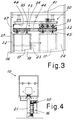
Figure 3 shows in greater detail a possible advantageous embodiment of thesystem 30 for transportation and replacement of the filters. - In particular, each
filter module 17 is hung from an associatedcarriage 43 which is displaceable alongrails 44 arranged on the ceiling of eachhousing 18 and extending in the direction of extraction/insertion of the module from/into the housing. Advantageously, this direction is transverse to the direction of displacement of theshuttle 32 on itsrails 33. - The
shuttle 32 comprises inturn rail sections 45 which are aligned with therails 44 of a housing when the shuttle is transported into the vicinity of this housing. In this way theactuator 35 may displace the filter unit with thecarriage 43 from therails 43 to therails 45 and vice versa. As can be seen again inFigure 3 , theactuator 35 may be a known linear actuator provided with amotorized slider 46 which engages asuitable operating end 47 of thecarriage 43 so as to controllably displace it betweenhousing 18 andshuttle 32. Other transfer devices may be imagined by the persons skilled in the art. - Each filter unit comprises advantageously an associated movement system in a mirror-image arrangement relative to the other one.
- Although the embodiment with two filter units in a mirror-image arrangement has been found to be particularly advantageous it is nevertheless also possible to use a single filter unit for example when the air flow to be treated is more limited. This is shown for example in
Figure 4 where essentially the T-shaped chamber for conveying the air to the filters has filter modules on one side only of the entry passage and therefore is provided with a single filter transportation system. As regards the rest the structure of the paint-spraying booth may be identical to that described above. - At this point it is clear how the predefined objects have been achieved. With a booth according to the invention it is possible to replace the filters cyclically in an automatic manner without having to stop the plant. Since the air flow is divided up by means of the plurality of filters, closing of one filter for removal and replacement thereof does not reduce excessively the air flow during the time needed for the whole operation.
- Obviously the description above of an embodiment applying the innovative principles of the present invention is provided by way of example of these innovative principles and must therefore not be regarded as limiting the scope of the rights claimed herein.
- For example, as may be now easily imagined by the person skilled in the art, the entry/exit zone may be divided into an entry zone where the new filters arrive and an exit zone where the used filters are transferred.
- Changing of the filters may be performed by means of a manual change command entered by the operator or by means of a cyclical procedure whereby a filter is changed after a certain operating time. Suitable sensors may be provided, these requesting automatic changing of a filter when it is detected that it is clogged up by more than a certain amount. During a complete changing operation, the filter modules may also be sequentially replaced one at a time (or in pairs, in the case of two filter units with associated independent automated systems), until all the filter modules have been completely replaced, without stopping the plant.
- In the case of disposable filters made of combustible material a method for high-temperature incineration of the used filters may be envisaged, said method using at least partly as fuel the filter itself and the paint contained in it. In addition to eliminating the filters it is possible to make advantageous use of the combustion for heat recovery from the combustion fumes.
Claims (9)
- Paint-spraying booth (10) comprising a paint-spraying chamber (11) in which the paint is sprayed and which is provided with an air flow for evacuation of the overspray which is conveyed to at least one filter unit (16) of the booth for filtering and separation of the paint overspray from the air flow, the filter unit comprising a plurality of replaceable filter modules (17), each filter module being removably contained inside a housing (18) in the filter unit, characterized in that it comprises an automated system (30) for removing and transporting each filter module (17) of the plurality between its housing (18) and a zone (31) for entry/exit of the filter modules into/from the booth, the automated system (30) comprising a motorized shuttle (32) which is displaceable along the filter modules (17) of the filter unit (16) in order to controllably load/unload the filter modules into/from the housings (18), the automated system (30) comprising transfer means (34) for controllably displacing a filter module (17) between its housing (18) and the shuttle (32) when the shuttle is transported in the vicinity of the housing, the transfer means (34) comprising an actuator and transfer device (35) and a carriage (43) from which the filter module (17) can be hung and which can be displaced on rails (44) inside the housing by means of the actuator or transfer device (35), the actuator or transfer device (35) being adapted to move the filter module (17) between its housing (18) and the shuttle (32) while keeping the filter module (17) suspended.
- Booth according to Claim 1, characterized in that the motorized shuttle (32) comprises rails (45) for accommodating the shuttle (43), which can be aligned with the rails (44) inside the housing for transfer of the carriage between housing and shuttle.
- Booth according to Claim 1, characterized in that it comprises a first passage (21) for entry of the air from the paint-spraying station into the filter modules (17) and a second passage (24) for exit of the air from the filter modules (17), and the housings (18) are arranged between first and second passages so as to connect the filter modules (17) of the filter unit in parallel with each other.
- Booth according to Claims 1 and 3, characterized in that the motorized shuttle (32) travels inside the second passage (24).
- Booth according to Claim 1, characterized in that it comprises a movable partition (37) which travels in sequence along air inlets (22) of the filter modules (17) so as to controllably close the air inlet in a housing (18).
- Booth according to Claim 1, characterized in that it comprises a transfer chamber (38) for transfer of the filter modules (37) between housings (18) and the entry/exit zone (31), the transfer chamber (38) being provided with a first door (39) communicating with the housings (18) and a second door (40) communicating with the outside of the booth towards the entry/exit zone (31).
- Booth according to Claim 1, characterized in that the filter units are two in number and arranged in a mirror-image layout underneath the floor of the paint-spraying chamber.
- Booth according to Claim 1, characterized in that a chamber (19) with a T-shaped cross-section is provided underneath the floor of the paint-spraying chamber, the horizontal part of the T forming a duct (20) for conveying the air flow which passes through the floor of the paint-spraying chamber and the vertical part of the T which forms a duct (21) inside which inlets (22) of the filter modules (17) emerge.
- Booth according to Claim 1, characterized in that further filters (26) and/or controlled gates for closing or throttling the exiting air flow are present downstream of the filter modules (17).
Priority Applications (1)
| Application Number | Priority Date | Filing Date | Title |
|---|---|---|---|
| SI201631176T SI3344363T1 (en) | 2015-09-01 | 2016-09-01 | Painting booth with automatic filter system |
Applications Claiming Priority (2)
| Application Number | Priority Date | Filing Date | Title |
|---|---|---|---|
| ITUB2015A003323A ITUB20153323A1 (en) | 2015-09-01 | 2015-09-01 | Spray booth with automated filtering system |
| PCT/IB2016/055225 WO2017037643A1 (en) | 2015-09-01 | 2016-09-01 | Painting booth with automatic filter system |
Publications (2)
| Publication Number | Publication Date |
|---|---|
| EP3344363A1 EP3344363A1 (en) | 2018-07-11 |
| EP3344363B1 true EP3344363B1 (en) | 2021-04-14 |
Family
ID=54601935
Family Applications (1)
| Application Number | Title | Priority Date | Filing Date |
|---|---|---|---|
| EP16779182.1A Active EP3344363B1 (en) | 2015-09-01 | 2016-09-01 | Painting booth with automatic filter system |
Country Status (13)
| Country | Link |
|---|---|
| US (1) | US10350626B2 (en) |
| EP (1) | EP3344363B1 (en) |
| JP (1) | JP6816115B2 (en) |
| KR (1) | KR20180048599A (en) |
| CN (1) | CN107949431B (en) |
| BR (1) | BR112018003964A2 (en) |
| CA (1) | CA2996442A1 (en) |
| ES (1) | ES2879660T3 (en) |
| IT (1) | ITUB20153323A1 (en) |
| MA (1) | MA47246A (en) |
| MX (1) | MX2018002571A (en) |
| SI (1) | SI3344363T1 (en) |
| WO (1) | WO2017037643A1 (en) |
Families Citing this family (14)
| Publication number | Priority date | Publication date | Assignee | Title |
|---|---|---|---|---|
| JP6576323B2 (en) * | 2016-12-14 | 2019-09-18 | 株式会社大気社 | Painting drying equipment |
| EP3610956B1 (en) * | 2018-08-14 | 2022-06-22 | Sturm Maschinen- & Anlagenbau GmbH | Painting installation and method for painting a workpiece |
| CN109013128A (en) * | 2018-10-30 | 2018-12-18 | 江苏同和智能装备有限公司 | A kind of paint spray booth's carton apparatus for automatic change and application method |
| IT201900024985A1 (en) * | 2019-12-20 | 2021-06-20 | Geico Spa | Spray booth with improved filter replacement system |
| IT201900025045A1 (en) * | 2019-12-20 | 2021-06-20 | Geico Spa | Painting booth with filter transport system |
| US11856833B2 (en) | 2020-01-22 | 2023-12-26 | Applied Materials, Inc. | In-line monitoring of OLED layer thickness and dopant concentration |
| JP7433449B2 (en) * | 2020-01-22 | 2024-02-19 | アプライド マテリアルズ インコーポレイテッド | In-line monitoring of OLED layer thickness and dopant concentration |
| DE102020204126A1 (en) | 2020-03-30 | 2021-09-30 | Volkswagen Aktiengesellschaft | Device for closing at least one opening when changing at least one filter element in an exhaust air filter system and a painting system with such |
| DE102020205792A1 (en) * | 2020-05-07 | 2021-11-11 | Dürr Systems Ag | Filter system, painting system and process for separating impurities |
| WO2022044189A1 (en) * | 2020-08-27 | 2022-03-03 | 株式会社大気社 | Painting equipment |
| US11878316B2 (en) * | 2020-12-15 | 2024-01-23 | Gallagher-Kaiser Corporation | Sliding drawer dry filtration system for a paint booth |
| CN113210172A (en) * | 2021-03-24 | 2021-08-06 | 中国汽车工业工程有限公司 | Paint mist treatment system capable of automatically replacing filter module |
| CN114832527A (en) * | 2022-03-16 | 2022-08-02 | 中国汽车工业工程有限公司 | Paint mist separation unit, paint mist separation device and spraying equipment |
| CN115921174B (en) * | 2023-02-21 | 2023-06-16 | 山东汇丰铸造科技股份有限公司 | High performance casting reel sprays paint and uses feed mechanism |
Family Cites Families (11)
| Publication number | Priority date | Publication date | Assignee | Title |
|---|---|---|---|---|
| JPS57197015A (en) * | 1981-05-27 | 1982-12-03 | Hitachi Plant Eng & Constr Co Ltd | Filter exchanging apparatus of air conditioner |
| DE3705634A1 (en) * | 1987-02-21 | 1988-09-01 | Metallgesellschaft Ag | METHOD AND DEVICE FOR CLEANING EXHAUST AIR FROM PAINT OR PAINT SPRAYING CABINS |
| GB9024406D0 (en) * | 1990-11-09 | 1991-01-02 | British Nuclear Fuels Plc | An improved filter change system |
| US5487766A (en) * | 1994-05-24 | 1996-01-30 | Vannier; Mervin R. | Portable air filtration apparatus |
| CA2126802C (en) * | 1994-06-27 | 1999-08-17 | Hermann Ophardt | Powder paint booth backflow filter apparatus |
| JP2996661B1 (en) * | 1999-02-19 | 2000-01-11 | 川崎重工業株式会社 | Filter block structure of dust removal device and its attachment / detachment device |
| ITMI20080963A1 (en) * | 2008-05-23 | 2009-11-24 | Geico Spa | PAINTING CABIN WITH DUST BLASTING SYSTEM |
| IT1397362B1 (en) * | 2009-12-02 | 2013-01-10 | Geico Spa | PAINTING CABIN WITH OVERSPRAY BLASTING SYSTEM AND DRY-ABATEMENT METHOD. |
| DE102011108631A1 (en) * | 2011-07-27 | 2013-01-31 | Eisenmann Ag | Method and device for separating overspray and installation with such |
| DE102013222301B4 (en) * | 2013-11-04 | 2024-01-25 | Dürr Systems Ag | Filter system for separating impurities from a raw gas stream containing impurities, painting system and method for separating impurities from a raw gas stream containing impurities |
| CN104858095B (en) * | 2015-06-15 | 2018-03-06 | 嘉兴启净涂装科技有限公司 | A kind of two-sided side-suction type dry type spraying applies system |
-
2015
- 2015-09-01 IT ITUB2015A003323A patent/ITUB20153323A1/en unknown
-
2016
- 2016-09-01 SI SI201631176T patent/SI3344363T1/en unknown
- 2016-09-01 US US15/754,007 patent/US10350626B2/en active Active
- 2016-09-01 MX MX2018002571A patent/MX2018002571A/en unknown
- 2016-09-01 EP EP16779182.1A patent/EP3344363B1/en active Active
- 2016-09-01 WO PCT/IB2016/055225 patent/WO2017037643A1/en active Application Filing
- 2016-09-01 MA MA047246A patent/MA47246A/en unknown
- 2016-09-01 BR BR112018003964A patent/BR112018003964A2/en active Search and Examination
- 2016-09-01 JP JP2018510400A patent/JP6816115B2/en active Active
- 2016-09-01 CA CA2996442A patent/CA2996442A1/en not_active Abandoned
- 2016-09-01 ES ES16779182T patent/ES2879660T3/en active Active
- 2016-09-01 KR KR1020187003385A patent/KR20180048599A/en active IP Right Grant
- 2016-09-01 CN CN201680046519.0A patent/CN107949431B/en not_active Expired - Fee Related
Non-Patent Citations (1)
| Title |
|---|
| None * |
Also Published As
| Publication number | Publication date |
|---|---|
| WO2017037643A1 (en) | 2017-03-09 |
| SI3344363T1 (en) | 2021-06-30 |
| MA47246A (en) | 2019-11-20 |
| MX2018002571A (en) | 2018-11-09 |
| KR20180048599A (en) | 2018-05-10 |
| US10350626B2 (en) | 2019-07-16 |
| JP6816115B2 (en) | 2021-01-20 |
| US20180243778A1 (en) | 2018-08-30 |
| CN107949431B (en) | 2020-02-21 |
| EP3344363A1 (en) | 2018-07-11 |
| ES2879660T3 (en) | 2021-11-22 |
| CA2996442A1 (en) | 2017-03-09 |
| CN107949431A (en) | 2018-04-20 |
| BR112018003964A2 (en) | 2018-09-25 |
| ITUB20153323A1 (en) | 2017-03-01 |
| JP2018531778A (en) | 2018-11-01 |
Similar Documents
| Publication | Publication Date | Title |
|---|---|---|
| EP3344363B1 (en) | Painting booth with automatic filter system | |
| EP3344364B1 (en) | Painting booth with filter changing system | |
| CN108367353B (en) | Additive manufacturing facility with continuously nested enclosed chambers | |
| RU2697452C2 (en) | Filtration unit, painting unit and operating method of filter unit | |
| CN108367351B (en) | Apparatus/method and facility for transporting additive manufacturing container/tray assemblies or trays | |
| JP2018531778A5 (en) | ||
| US11085695B2 (en) | Treatment plant and method for treating workpieces | |
| US20150367372A1 (en) | Device for separating overspray | |
| DE102008036322A1 (en) | Interim storage for intermediate storage of objects to be painted | |
| US20190217320A1 (en) | Treatment installation and method for treating workpieces | |
| CN108212632B (en) | Powder coating cabin, powder coating installation and method for operating the powder coating cabin | |
| EP3742096A1 (en) | Drying oven and drying method | |
| WO2021124181A1 (en) | Painting booth with filter transport system | |
| KR20180050283A (en) | Painting Booth with Filter Change System | |
| CN215901115U (en) | Filter device and paint spraying device for spraying paint to workpiece | |
| CN113457288B (en) | Device and painting installation comprising such a device | |
| WO2021124183A1 (en) | Painting booth with improved system for replacement of the filters | |
| EP4076767A1 (en) | Painting booth with manual filter-changing system | |
| US9751103B2 (en) | Varnishing plant for body shops | |
| RU119746U1 (en) | LINE FOR BLASTING AND CANNING OF METAL-ROLLING |
Legal Events
| Date | Code | Title | Description |
|---|---|---|---|
| STAA | Information on the status of an ep patent application or granted ep patent |
Free format text: STATUS: UNKNOWN |
|
| STAA | Information on the status of an ep patent application or granted ep patent |
Free format text: STATUS: THE INTERNATIONAL PUBLICATION HAS BEEN MADE |
|
| PUAI | Public reference made under article 153(3) epc to a published international application that has entered the european phase |
Free format text: ORIGINAL CODE: 0009012 |
|
| STAA | Information on the status of an ep patent application or granted ep patent |
Free format text: STATUS: REQUEST FOR EXAMINATION WAS MADE |
|
| 17P | Request for examination filed |
Effective date: 20180112 |
|
| AK | Designated contracting states |
Kind code of ref document: A1 Designated state(s): AL AT BE BG CH CY CZ DE DK EE ES FI FR GB GR HR HU IE IS IT LI LT LU LV MC MK MT NL NO PL PT RO RS SE SI SK SM TR |
|
| AX | Request for extension of the european patent |
Extension state: BA ME |
|
| DAX | Request for extension of the european patent (deleted) | ||
| RAV | Requested validation state of the european patent: fee paid |
Extension state: MA Effective date: 20180112 |
|
| STAA | Information on the status of an ep patent application or granted ep patent |
Free format text: STATUS: EXAMINATION IS IN PROGRESS |
|
| 17Q | First examination report despatched |
Effective date: 20191017 |
|
| RIC1 | Information provided on ipc code assigned before grant |
Ipc: B05B 14/43 20180101AFI20201201BHEP |
|
| GRAP | Despatch of communication of intention to grant a patent |
Free format text: ORIGINAL CODE: EPIDOSNIGR1 |
|
| RIC1 | Information provided on ipc code assigned before grant |
Ipc: B05B 14/43 20180101ALI20201207BHEP Ipc: B01D 46/00 20060101AFI20201207BHEP |
|
| STAA | Information on the status of an ep patent application or granted ep patent |
Free format text: STATUS: GRANT OF PATENT IS INTENDED |
|
| INTG | Intention to grant announced |
Effective date: 20210114 |
|
| GRAS | Grant fee paid |
Free format text: ORIGINAL CODE: EPIDOSNIGR3 |
|
| GRAA | (expected) grant |
Free format text: ORIGINAL CODE: 0009210 |
|
| STAA | Information on the status of an ep patent application or granted ep patent |
Free format text: STATUS: THE PATENT HAS BEEN GRANTED |
|
| AK | Designated contracting states |
Kind code of ref document: B1 Designated state(s): AL AT BE BG CH CY CZ DE DK EE ES FI FR GB GR HR HU IE IS IT LI LT LU LV MC MK MT NL NO PL PT RO RS SE SI SK SM TR |
|
| REG | Reference to a national code |
Ref country code: GB Ref legal event code: FG4D |
|
| REG | Reference to a national code |
Ref country code: CH Ref legal event code: EP |
|
| REG | Reference to a national code |
Ref country code: DE Ref legal event code: R096 Ref document number: 602016056119 Country of ref document: DE |
|
| REG | Reference to a national code |
Ref country code: IE Ref legal event code: FG4D |
|
| REG | Reference to a national code |
Ref country code: AT Ref legal event code: REF Ref document number: 1381794 Country of ref document: AT Kind code of ref document: T Effective date: 20210515 |
|
| REG | Reference to a national code |
Ref country code: SE Ref legal event code: TRGR |
|
| REG | Reference to a national code |
Ref country code: LT Ref legal event code: MG9D |
|
| REG | Reference to a national code |
Ref country code: AT Ref legal event code: MK05 Ref document number: 1381794 Country of ref document: AT Kind code of ref document: T Effective date: 20210414 |
|
| REG | Reference to a national code |
Ref country code: NL Ref legal event code: MP Effective date: 20210414 |
|
| PG25 | Lapsed in a contracting state [announced via postgrant information from national office to epo] |
Ref country code: FI Free format text: LAPSE BECAUSE OF FAILURE TO SUBMIT A TRANSLATION OF THE DESCRIPTION OR TO PAY THE FEE WITHIN THE PRESCRIBED TIME-LIMIT Effective date: 20210414 Ref country code: NL Free format text: LAPSE BECAUSE OF FAILURE TO SUBMIT A TRANSLATION OF THE DESCRIPTION OR TO PAY THE FEE WITHIN THE PRESCRIBED TIME-LIMIT Effective date: 20210414 Ref country code: LT Free format text: LAPSE BECAUSE OF FAILURE TO SUBMIT A TRANSLATION OF THE DESCRIPTION OR TO PAY THE FEE WITHIN THE PRESCRIBED TIME-LIMIT Effective date: 20210414 Ref country code: HR Free format text: LAPSE BECAUSE OF FAILURE TO SUBMIT A TRANSLATION OF THE DESCRIPTION OR TO PAY THE FEE WITHIN THE PRESCRIBED TIME-LIMIT Effective date: 20210414 Ref country code: BG Free format text: LAPSE BECAUSE OF FAILURE TO SUBMIT A TRANSLATION OF THE DESCRIPTION OR TO PAY THE FEE WITHIN THE PRESCRIBED TIME-LIMIT Effective date: 20210714 Ref country code: AT Free format text: LAPSE BECAUSE OF FAILURE TO SUBMIT A TRANSLATION OF THE DESCRIPTION OR TO PAY THE FEE WITHIN THE PRESCRIBED TIME-LIMIT Effective date: 20210414 |
|
| REG | Reference to a national code |
Ref country code: ES Ref legal event code: FG2A Ref document number: 2879660 Country of ref document: ES Kind code of ref document: T3 Effective date: 20211122 |
|
| PG25 | Lapsed in a contracting state [announced via postgrant information from national office to epo] |
Ref country code: NO Free format text: LAPSE BECAUSE OF FAILURE TO SUBMIT A TRANSLATION OF THE DESCRIPTION OR TO PAY THE FEE WITHIN THE PRESCRIBED TIME-LIMIT Effective date: 20210714 Ref country code: PL Free format text: LAPSE BECAUSE OF FAILURE TO SUBMIT A TRANSLATION OF THE DESCRIPTION OR TO PAY THE FEE WITHIN THE PRESCRIBED TIME-LIMIT Effective date: 20210414 Ref country code: PT Free format text: LAPSE BECAUSE OF FAILURE TO SUBMIT A TRANSLATION OF THE DESCRIPTION OR TO PAY THE FEE WITHIN THE PRESCRIBED TIME-LIMIT Effective date: 20210816 Ref country code: RS Free format text: LAPSE BECAUSE OF FAILURE TO SUBMIT A TRANSLATION OF THE DESCRIPTION OR TO PAY THE FEE WITHIN THE PRESCRIBED TIME-LIMIT Effective date: 20210414 Ref country code: IS Free format text: LAPSE BECAUSE OF FAILURE TO SUBMIT A TRANSLATION OF THE DESCRIPTION OR TO PAY THE FEE WITHIN THE PRESCRIBED TIME-LIMIT Effective date: 20210814 Ref country code: LV Free format text: LAPSE BECAUSE OF FAILURE TO SUBMIT A TRANSLATION OF THE DESCRIPTION OR TO PAY THE FEE WITHIN THE PRESCRIBED TIME-LIMIT Effective date: 20210414 Ref country code: GR Free format text: LAPSE BECAUSE OF FAILURE TO SUBMIT A TRANSLATION OF THE DESCRIPTION OR TO PAY THE FEE WITHIN THE PRESCRIBED TIME-LIMIT Effective date: 20210715 |
|
| REG | Reference to a national code |
Ref country code: DE Ref legal event code: R097 Ref document number: 602016056119 Country of ref document: DE |
|
| PG25 | Lapsed in a contracting state [announced via postgrant information from national office to epo] |
Ref country code: SK Free format text: LAPSE BECAUSE OF FAILURE TO SUBMIT A TRANSLATION OF THE DESCRIPTION OR TO PAY THE FEE WITHIN THE PRESCRIBED TIME-LIMIT Effective date: 20210414 Ref country code: SM Free format text: LAPSE BECAUSE OF FAILURE TO SUBMIT A TRANSLATION OF THE DESCRIPTION OR TO PAY THE FEE WITHIN THE PRESCRIBED TIME-LIMIT Effective date: 20210414 Ref country code: CZ Free format text: LAPSE BECAUSE OF FAILURE TO SUBMIT A TRANSLATION OF THE DESCRIPTION OR TO PAY THE FEE WITHIN THE PRESCRIBED TIME-LIMIT Effective date: 20210414 Ref country code: EE Free format text: LAPSE BECAUSE OF FAILURE TO SUBMIT A TRANSLATION OF THE DESCRIPTION OR TO PAY THE FEE WITHIN THE PRESCRIBED TIME-LIMIT Effective date: 20210414 Ref country code: DK Free format text: LAPSE BECAUSE OF FAILURE TO SUBMIT A TRANSLATION OF THE DESCRIPTION OR TO PAY THE FEE WITHIN THE PRESCRIBED TIME-LIMIT Effective date: 20210414 Ref country code: RO Free format text: LAPSE BECAUSE OF FAILURE TO SUBMIT A TRANSLATION OF THE DESCRIPTION OR TO PAY THE FEE WITHIN THE PRESCRIBED TIME-LIMIT Effective date: 20210414 |
|
| PLBE | No opposition filed within time limit |
Free format text: ORIGINAL CODE: 0009261 |
|
| STAA | Information on the status of an ep patent application or granted ep patent |
Free format text: STATUS: NO OPPOSITION FILED WITHIN TIME LIMIT |
|
| 26N | No opposition filed |
Effective date: 20220117 |
|
| REG | Reference to a national code |
Ref country code: SE Ref legal event code: EUG |
|
| REG | Reference to a national code |
Ref country code: CH Ref legal event code: PL |
|
| REG | Reference to a national code |
Ref country code: BE Ref legal event code: MM Effective date: 20210930 |
|
| GBPC | Gb: european patent ceased through non-payment of renewal fee |
Effective date: 20210901 |
|
| PG25 | Lapsed in a contracting state [announced via postgrant information from national office to epo] |
Ref country code: IS Free format text: LAPSE BECAUSE OF FAILURE TO SUBMIT A TRANSLATION OF THE DESCRIPTION OR TO PAY THE FEE WITHIN THE PRESCRIBED TIME-LIMIT Effective date: 20210814 Ref country code: MC Free format text: LAPSE BECAUSE OF FAILURE TO SUBMIT A TRANSLATION OF THE DESCRIPTION OR TO PAY THE FEE WITHIN THE PRESCRIBED TIME-LIMIT Effective date: 20210414 Ref country code: AL Free format text: LAPSE BECAUSE OF FAILURE TO SUBMIT A TRANSLATION OF THE DESCRIPTION OR TO PAY THE FEE WITHIN THE PRESCRIBED TIME-LIMIT Effective date: 20210414 |
|
| REG | Reference to a national code |
Ref country code: SI Ref legal event code: KO00 Effective date: 20220519 |
|
| PG25 | Lapsed in a contracting state [announced via postgrant information from national office to epo] |
Ref country code: SE Free format text: LAPSE BECAUSE OF NON-PAYMENT OF DUE FEES Effective date: 20210902 Ref country code: LU Free format text: LAPSE BECAUSE OF NON-PAYMENT OF DUE FEES Effective date: 20210901 Ref country code: IT Free format text: LAPSE BECAUSE OF FAILURE TO SUBMIT A TRANSLATION OF THE DESCRIPTION OR TO PAY THE FEE WITHIN THE PRESCRIBED TIME-LIMIT Effective date: 20210414 Ref country code: IE Free format text: LAPSE BECAUSE OF NON-PAYMENT OF DUE FEES Effective date: 20210901 Ref country code: GB Free format text: LAPSE BECAUSE OF NON-PAYMENT OF DUE FEES Effective date: 20210901 Ref country code: BE Free format text: LAPSE BECAUSE OF NON-PAYMENT OF DUE FEES Effective date: 20210930 |
|
| PG25 | Lapsed in a contracting state [announced via postgrant information from national office to epo] |
Ref country code: LI Free format text: LAPSE BECAUSE OF NON-PAYMENT OF DUE FEES Effective date: 20210930 Ref country code: CH Free format text: LAPSE BECAUSE OF NON-PAYMENT OF DUE FEES Effective date: 20210930 |
|
| PG25 | Lapsed in a contracting state [announced via postgrant information from national office to epo] |
Ref country code: HU Free format text: LAPSE BECAUSE OF FAILURE TO SUBMIT A TRANSLATION OF THE DESCRIPTION OR TO PAY THE FEE WITHIN THE PRESCRIBED TIME-LIMIT; INVALID AB INITIO Effective date: 20160901 |
|
| P01 | Opt-out of the competence of the unified patent court (upc) registered |
Effective date: 20230517 |
|
| PG25 | Lapsed in a contracting state [announced via postgrant information from national office to epo] |
Ref country code: CY Free format text: LAPSE BECAUSE OF FAILURE TO SUBMIT A TRANSLATION OF THE DESCRIPTION OR TO PAY THE FEE WITHIN THE PRESCRIBED TIME-LIMIT Effective date: 20210414 |
|
| PGFP | Annual fee paid to national office [announced via postgrant information from national office to epo] |
Ref country code: FR Payment date: 20230925 Year of fee payment: 8 Ref country code: DE Payment date: 20230927 Year of fee payment: 8 |
|
| PGFP | Annual fee paid to national office [announced via postgrant information from national office to epo] |
Ref country code: ES Payment date: 20231002 Year of fee payment: 8 |