EP3344357B1 - Kanal zur verwendung in einem system zur trennung von in einem fluid suspendierten partikeln und verfahren zum entwurf solch eines kanals - Google Patents
Kanal zur verwendung in einem system zur trennung von in einem fluid suspendierten partikeln und verfahren zum entwurf solch eines kanals Download PDFInfo
- Publication number
- EP3344357B1 EP3344357B1 EP16840984.5A EP16840984A EP3344357B1 EP 3344357 B1 EP3344357 B1 EP 3344357B1 EP 16840984 A EP16840984 A EP 16840984A EP 3344357 B1 EP3344357 B1 EP 3344357B1
- Authority
- EP
- European Patent Office
- Prior art keywords
- duct
- trapping
- bay
- channel
- main channel
- Prior art date
- Legal status (The legal status is an assumption and is not a legal conclusion. Google has not performed a legal analysis and makes no representation as to the accuracy of the status listed.)
- Active
Links
- 239000002245 particle Substances 0.000 title claims description 88
- 239000012530 fluid Substances 0.000 title claims description 66
- 238000000034 method Methods 0.000 title description 17
- 238000005192 partition Methods 0.000 claims description 16
- 238000007514 turning Methods 0.000 claims description 5
- 238000011144 upstream manufacturing Methods 0.000 claims description 4
- 238000007599 discharging Methods 0.000 claims description 2
- 230000007704 transition Effects 0.000 claims 2
- 238000000926 separation method Methods 0.000 description 22
- 238000004088 simulation Methods 0.000 description 10
- 238000005206 flow analysis Methods 0.000 description 7
- 238000009825 accumulation Methods 0.000 description 6
- 230000003068 static effect Effects 0.000 description 4
- 239000000428 dust Substances 0.000 description 3
- 238000004458 analytical method Methods 0.000 description 2
- 230000000694 effects Effects 0.000 description 2
- 238000000605 extraction Methods 0.000 description 2
- 239000007789 gas Substances 0.000 description 2
- 239000007788 liquid Substances 0.000 description 2
- 238000004519 manufacturing process Methods 0.000 description 2
- 239000004576 sand Substances 0.000 description 2
- 239000007787 solid Substances 0.000 description 2
- XLYOFNOQVPJJNP-UHFFFAOYSA-N water Substances O XLYOFNOQVPJJNP-UHFFFAOYSA-N 0.000 description 2
- 238000010586 diagram Methods 0.000 description 1
- 239000006194 liquid suspension Substances 0.000 description 1
- 239000000725 suspension Substances 0.000 description 1
Images


Classifications
-
- B—PERFORMING OPERATIONS; TRANSPORTING
- B01—PHYSICAL OR CHEMICAL PROCESSES OR APPARATUS IN GENERAL
- B01D—SEPARATION
- B01D21/00—Separation of suspended solid particles from liquids by sedimentation
- B01D21/0039—Settling tanks provided with contact surfaces, e.g. baffles, particles
- B01D21/0054—Plates in form of a coil
-
- B—PERFORMING OPERATIONS; TRANSPORTING
- B01—PHYSICAL OR CHEMICAL PROCESSES OR APPARATUS IN GENERAL
- B01D—SEPARATION
- B01D21/00—Separation of suspended solid particles from liquids by sedimentation
- B01D21/24—Feed or discharge mechanisms for settling tanks
- B01D21/245—Discharge mechanisms for the sediments
-
- B—PERFORMING OPERATIONS; TRANSPORTING
- B01—PHYSICAL OR CHEMICAL PROCESSES OR APPARATUS IN GENERAL
- B01D—SEPARATION
- B01D21/00—Separation of suspended solid particles from liquids by sedimentation
- B01D21/0003—Making of sedimentation devices, structural details thereof, e.g. prefabricated parts
-
- B—PERFORMING OPERATIONS; TRANSPORTING
- B01—PHYSICAL OR CHEMICAL PROCESSES OR APPARATUS IN GENERAL
- B01D—SEPARATION
- B01D21/00—Separation of suspended solid particles from liquids by sedimentation
- B01D21/26—Separation of sediment aided by centrifugal force or centripetal force
- B01D21/265—Separation of sediment aided by centrifugal force or centripetal force by using a vortex inducer or vortex guide, e.g. coil
-
- G—PHYSICS
- G06—COMPUTING; CALCULATING OR COUNTING
- G06F—ELECTRIC DIGITAL DATA PROCESSING
- G06F30/00—Computer-aided design [CAD]
- G06F30/20—Design optimisation, verification or simulation
Definitions
- the presently disclosed subject matter refers to the field of separating particles suspended in a fluid, more particularly, to static separation of such particles in a substantially laminate fluid flow within a curved duct.
- a duct for separating particles suspended in a fluid comprising at least one trapping-bay portion having a main channel extending along a curved central line defining a fluid flow direction and one or more trapping bays configured for trapping at least a part of said particles and coextensive with the main channel along the central line, the main channel and at least one of the bays are as follows in a cross-section of the trapping-bay portion taken perpendicularly to said central line:
- the main channel and/or the trapping bay can have in the above cross-section a dimension between its inner and outer walls essentially greater than that between its lower and upper walls.
- the trapping bay can further have a stepped configuration with a number of mutually perpendicular walls.
- the duct can be arcuate or spiral at least along some of its portions.
- the trapping-bay portion can constitute at least a portion of a turning of a spiral or of a circle.
- the duct comprises at least one basic channel portion upstream of the trapping-bay portion, the basic channel portion having, at least at the area of its merger with the trapping-bay portion, shape and dimensions identical to those of the main channel of the trapping-bay portion.
- the duct comprises at least one partitioned portion, comprising a main channel and a trapping bay similar to those of the trapping-bay portion upstream of the partitioned portion, and further comprising at least one partition wall extending along a length of the partitioned portion and disposed between outer or inner wall of the main channel and the central line.
- the wall is configured to enable continuation of fluid flow along the main channel while preventing movement of particles from the trapping-bay portion back to the main channel and to be extracted while flowing within the partitioned portion.
- the partition wall can be disposed closer to the trapping bay than to the central line, and configured to enable continuation of fluid flow along the main channel and along the trapping bay while preventing movement of particles trapped within the bay back to the main channel.
- the duct can comprise an inlet for receiving therein fluid from an external source and each of said main channel and the bay of the trapping-bay portion or of the partitioned portion can include its own outlet for discharging fluid therefrom.
- the duct may define a fluid flow direction and may comprise at least one segment having a polygonal shape defined by at least four duct walls including an outer duct wall, an inner duct wall, an upper duct wall and a lower duct wall, in first a cross-sectional plane of the segment passing through the central line, at least one of the inner and outer duct walls of said segment having a profile, in a second cross-sectional plane perpendicular to the first cross-sectional plane and comprising the central line, which is defined by a varying distance between the corresponding wall and the central line.
- the profile of at least one of the inner and outer walls can have an undulating, e.g. sinusoidal, shape.
- a duct according to the above aspect can be used in any system for separating particles suspended in a fluid, and particularly, in static systems, which are free of moving components or other components actively operated to provide the separation, which can result in reducing the cost and failure rates that are typical in non-static systems.
- a duct according to the presently disclosed subject matter for use in a static system for separating particles suspended in a fluid, can have several types of duct portions, at least some of which can be curved. Each type of a duct portion can extend along a part of the duct's length, as desired, for controlling flow parameters in order to facilitate the accumulation of particles required to be extracted from the fluid.
- the particles having similar parameters tend to follow similar trajectories within the flow, which can lie close to or far from a given duct's wall.
- the duct is arcuate or spiral along at least a part of its length, and has corresponding outer and inner walls, heavier or larger particles will normally tend to flow along the outer wall of the duct and lighter or smaller particles tend to flow near the inner wall of the duct.
- the duct can have a central line corresponding to the flow direction, a basic polygonal shape in its cross-section taken perpendicular to this central line, can include straight or curved portions extending along different segments of the central line, and can be configured to provide, at least along some of these portions, a desired laminar flow of a fluid.
- the polygonal shape of the duct in the above cross-section can be such that the duct's dimension between the inner and outer wall is essentially greater than that between the upper and lower walls.
- the ratio between the former and the latter dimensions can be at least 5:1, more particularly, at least 10:1, and still more particularly, at least 15:1.
- the duct portions can differ by their shape in a cross-section taken perpendicular to the central line and/or in a cross-section taken along the central line perpendicularly to the inner and outer duct walls. In addition or alternatively, they can also differ by the shape of the central line, e.g. its radius of curvature, and/or by their extension along the central line. Thus, in a duct or a part thereof having a radius of curvature, different portions can have a different angular span. In general, the angular span of the duct portions can be not less than 25 degrees. In a duct having one or more turnings of a substantially flat spiral, e.g. as shown in Fig.
- portions of the duct relating to different turnings will have different radii of curvature.
- Each type of a duct portion can appear more than once along the length of the duct with the same or different various cross-sectional shapes and dimensions. In accordance with one aspect of the presently disclosed subject matter, these differences can be used, when designing the duct, to cause the particles to follow desired trajectories within the duct.
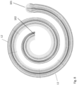
- the duct 100 has an inlet 101 and an outlet 102, and a spiral central line X extending therebetween, and it can be segmented along this central line into portions of various types, such as basic channel portions, trapping-bay portions, and partitioned portions described below in more details, or portions of the same type having different geometry/dimensions.
- Each portion extends between transitional locations 103 and is defined by its angular span L and radius of curvature R, which can be selected to achieve within the portion a desired hydrodynamic performance of the fluid flow, and particularly, particles to be separated, according to a pre-determined plan, which can be generated, for example, as described below.
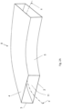
- a basic channel portion 8 is shown in Fig. 2A , and it has a basic rectangular cross-sectional shape in a plane perpendicular to the central line, defined by four channel walls: outer and inner channel walls 3 and 5, and lower and upper channel walls 2 and 4, respectively.
- One basic channel portion can extend, for example, from the duct inlet 101 along a part of the first turning thereof.
- the trapping-bay portion downstream of the basic channel portion, and adjacent the outer and/or inner channel walls, can facilitate the accumulation of particles distributed as mentioned above in said trapping-bay portion whilst reducing the amount of fluid accompanying these particles.
- the trapping-bay portion can thus comprise a main channel, optionally constituting a continuation of the basic channel portion described above, at least along a majority of the cross-sectional area of the basic channel portion, and at least one bay merging and coextensive with the main channel, configured to accommodate therein particles of at least one type.
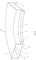
- the trapping-bay portion comprises a main channel 11 and a trapping bay 12 coextensive with the main channel 11 along the central line X.
- the main channel 11 in this embodiment, has a rectangular shape defined by four channel walls: outer and inner channel walls 3 and 5, and lower and upper channel walls 2 and 4, respectively.
- the trapping bay 12 protrudes from the inner channel wall 5 away from the central line X and has bay walls 6,7,2 generally parallel to the corresponding walls of the main channel oriented in the same way. Namely, the bay walls 6,7,2 are parallel or coincide to the respective channel walls 4, 5, 2.
- the area of the bay 12 is smaller than that of the main channel 11 and some of its walls have lengths that are shorter than those of the corresponding walls of the main channel.
- the dimension of the bay between its inner and outer walls can be essentially greater than that between its upper and lower walls.
- the ratio between the former and the latter dimensions can be at least 5:1, more particularly, at least 10:1, and still more particularly, at least 15:1.
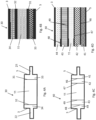
- FIG. 3 illustrates a cross-section of an example of a trapping-bay portion 20, which differs from the trapping-bay portion 10 by having two trapping bays, an inner trapping bay 21 and an outer trapping bay 22, each protruding from the corresponding wall.
- the areas of each of the bays 21 and 22 are smaller than that of the main channel 11 and some of their walls have lengths that are shorter than those of the corresponding walls of the main channel.
- Bays like the bay 12 shown in Fig. 2B and 21 as shown in Fig. 3 which are associated with the inner wall of the channel 11, will capture the particles that will move and congregate due to the centripetal force that applies on particles that are light and small.
- Bay 22 in Fig 3 will capture the particles that will move and congregate due to the inertia force that applies on particles that are heavy and large.
- Each of the trapping bays 12, 21 and 22 can have a configuration different from those shown in Fig. 2B or Fig. 3 .
- they can be located at different heights along the inner or outer walls of the main channel, their width or length can vary, and the number of walls can change, for example, in case the bay has a stepped shape.
- Trapped particles can be extracted out of the system directly from trapping bays or after being directed into partitioned portions.
- partitioned portions constructed throughout the duct, each at a different location and may vary in their partition positioning within the main channel.
- the partitioned portions may be constructed downstream of trapping-bay portions or downstream of basic channel portions, each to target a zone that is expected to have accumulation of certain particles.
- Particles captured within the partitioned channel can then be extracted, for example through some exit ports placed along the channel.
- the rest of the fluid continues to flow within the main channel.
- a change can be implemented to the cross-section and the central line curvature of the duct by additional duct portions in order to change the fluid flow dynamics. This will cause additional particles to accumulate within a specific zone of the duct, following by adding new partitioned portions in order to capture these particles.
- This process of accumulating and extracting particles can be repeated a desired number of times along the duct. The same type of particles can be extracted in multiple places in order to capture those escaped from upstream extractions.
- partitioned portions are illustrated in Figs. 4A and 4B , where a partitioned portion 30 is shown as comprising, in addition to the main channel 11 and the trapping bays 21 and 22, two partition zones 33 and 34, constructed by two walls 31 and 32, which extend between the upper and lower walls of the main channel and continue along a length of the partitioned portion, to enable the continuation of the fluid flow along the main channel and along the trapping bay while preventing the return of particles trapped within the bay back to the main channel.
- the location of each partition wall is configured to allow trapping of particles accumulated in the trapping bays while keeping other fluid out of the partitioned area.
- both partition walls 31 and 32 are located near the bay to allow keeping more of the clean fluid within the main channel.
- a partition portion 40 has multiple partition zones 41 to 44 separated by walls 46 to 49 that extend between the upper and lower walls of the main channel and along a length of the partitioned portion 40. Such configuration allows the separation of the fluid into multiple types of particles that will have different accumulation zones along the main channel.
- the duct according to the presently disclosed subject matter can have, in at least one segment thereof, inner and outer walls, at least one of which has, in a cross-sectional plane of the segment passing through the central line and crossing the walls, a profile defined by a varying distance between the corresponding wall and the central line.
- Example of one such segment is shown in Fig. 5 , where a segment 50 has inner and outer duct walls 55 and 53, which in its cross-sectional plane passing through the central line X1 and crossing the walls 55 and 53, have a profile defined by a varying distance between the corresponding wall and the central line. More particularly, each of the inner and outer walls 55 and 53 has an undulating shape.
- a plurality of particles separation systems having ducts formed with portions as described above can be used in combination, e.g. as illustrated in Fig. 6 .
- At least a part of the ducts can each enable the separation of an incoming fluid into three channels, one - the main channel and two the trapping-bay and partitioned portions.
- the latter portions are configured to output particles trapped thereby whilst the main channel is configured to feed the residual fluid into the next separation system, until desired separation is complete.
- fluid 204 flows through channel 202 into the first separation system 206, such as described above, where some of the particles are trapped and extracted into output channel 210 and others into channel 208, while the residue fluid 232 flows out as an output.
- the fluid from the output channel 210 thus flows into a second separation system 212 and is processed using trapping-bay and partitioned portions into output 234, while output channel 214 leads fluid into separation system 218 where it is processed using trapping-bay and partitioned portions into outputs 242, 244, 246.
- the fluid within output channel 208 goes into separation system 216 and is processed using trapping-bay and partitioned portions into outputs 226, 228, 230 .
- a duct according to the presently described subject matter can be used with fluids that contain particles of various types and characteristics.
- the particles can be in the form of solid, liquid or gas particles suspended in a fluid and need to be separated at least partially by means of the trapping-bays and partitioned portions, as described above.
- a computer-implemented method can be used, one example of which is described below with reference to Fig. 7 . To perform such method the computer should be provided with appropriate software allowing to perform flow analysis and particles tracing simulation referred to in Steps 3 and 4 below.
- Step 1 initial process parameters are input into a computer, including parameters of the fluid, particles suspended in the fluid, flow parameters and desired extent of separation between the fluid and the particles to be discharged.
- the fluid parameters can include viscosity, velocity, temperature and pressure, which the fluid is expected to have when entering the duct or flowing along the duct.
- the initial process parameters can be include operational parameters dictated by the required environment of operation and working standards.
- the initial parameters of the particles suspended within the fluid can include at least their sizes, specific weights and nature.
- the specific weights of a particle can be higher than the specific weight of the carrying fluid, however, when it is coated by a layer of air, the effect of the air in reducing the gross specific weight of particle plus air can be substantial.
- the basic duct parameters are selected based on the initial process conditions.
- the basic duct parameters relate at least to the basic geometry of the duct and can comprise dimensions of the duct, such as its length along the central line of the duct defining a fluid flow direction, duct profile curvature along the central line, planned exit ports, the duct's shape in a cross-section taken perpendicular to the central line, and its width and height in this cross-section.
- Step 3 a flow analysis is performed of the flow which the fluid entering the duct with the initial process parameters obtained in Step 1 will have when flowing along the duct having the basic duct parameters defined in Step 2; the flow analysis can provide at least the assessment of the velocity and pressure profiles that develop along the duct and calculating the time the particles will spend within the duct.
- Step 4 a particle tracing simulation is performed with respect to the particles having the initial parameters obtained in Step 1, to study their behavior in the flow analyzed in Step 3 above.
- This analysis can provide information about the particles' distribution in the duct having the basic parameters defined in Step 2, percentage of separation that can be obtained in the duct, efficiency of duct profiles, and time spent along the duct.
- By analyzing the simulation results one can target potential locations in which trapping-bay and partition portions can be formed in the duct.
- Fig. 8 schematically illustrates an example of such results obtained for a spiral shaped duct, in which the fluid was water and particles were of sand dust.
- L1 and L2 are examples of candidate zone for having trapping bays on the outer wall of the duct in order to trap particles shown as accumulated along this wall.
- a trapping bay could be added, for example, in between L1 and L2 in order to control the flow to accelerate particles accumulation towards the outer wall.
- the duct parameters are updated based on the particle tracing simulation.
- the updated parameters can include overall or local changes in the duct geometry such as incorporating trapping-bay and, optionally, partition portions and/or changing dimensions of the duct basic channel in its different cross-sections and/or the length of the duct /or its curvature of duct portions.
- Steps 6 and 7 the flow analysis and the particle tracing simulations are performed similar to those performed in Steps 4 and 5, and if the desired extent of separation is not achieved, Steps 5, 6 and 7 are performed again as many times as necessary until the extent of separation as analyzed corresponds to the desired extent of separation.
- Step 8 the geometry of the duct is output for use in manufacturing the duct accordingly by any suitable method known in the art.
- the fluid parameters can include viscosity, velocity, temperature and pressure, which the fluid is expected to have when entering the duct or flowing along the duct.
- the initial process parameters can be include operational parameters dictated by the required environment of operation and working standards.
- the initial parameters of the particles suspended within the fluid can include at least their sizes, specific weights and nature.
- the specific weights of a particle can be higher than the specific weight of the carrying fluid, however, when it is coated by a layer of air, the effect of the air in reducing the gross specific weight of particle plus air, can be substantial.
- the basic duct parameters are selected based on the initial process conditions.
- the basic duct parameters relate at least to the basic geometry of the duct and can comprise dimensions of the duct, such as its length along the central line of the duct defining a fluid flow direction, duct profile curvature along the central line, planned exit ports, the duct's shape in a cross-section taken perpendicular to the central line, and its width and height in this cross-section.
- Step 3 a flow analysis is performed of the flow, which the fluid entering the duct with the initial process parameters obtained in Step 1, will have when flowing along the duct having the basic duct parameters defined in Step 2; the flow analysis can provide at least the assessment of the velocity and pressure profiles that develop along the duct and calculating the time the particles will spend within the duct.
- Step 4 a particle tracing simulation is performed with respect to the particles having the initial parameters obtained in Step 1, to study their behavior in the flow analyzed in Step 3 above.
- This analysis can provide information about the particles' distribution in the duct having the basic parameters defined in Step 2, percentage of separation that can be obtained in the duct, efficiency of duct profiles, and time spent along the duct.
- By analyzing the simulation results one can target potential locations, in which trapping-bay and partition portions can be formed in the duct.
- Fig. 8 schematically illustrates an example of such results obtained for a spiral shaped duct, in which the fluid was water and particles were of sand dust.
- L1 and L2 are examples of candidate zone for having trapping bays on the outer wall of the duct in order to trap particles shown as accumulated along this wall.
- a trapping bay could be added, for example, in between L1 and L2 in order to control the flow to accelerate particles accumulation towards the outer wall.
- the duct parameters are updated based on the particle tracing simulation.
- the updated parameters can include overall or local changes in the duct geometry such as incorporating trapping-bay and, optionally, partition portions and/or changing dimensions of the duct basic channel in its different cross-sections and/or the length of the duct /or its curvature of duct portions.
- Steps 6 and 7 the flow analysis and the particle tracing simulations are performed similar to those performed in Steps 4 and 5, and if the desired extent of separation is not achieved, Steps 5, 6 and 7 are performed again as many times as necessary until the extent of separation as analyzed corresponds to the desired extent of separation.
- Step 8 the geometry of the duct is output for use in manufacturing the duct accordingly by any suitable method known in the art.
Landscapes
- Chemical Kinetics & Catalysis (AREA)
- Chemical & Material Sciences (AREA)
- Engineering & Computer Science (AREA)
- Theoretical Computer Science (AREA)
- Physics & Mathematics (AREA)
- Computer Hardware Design (AREA)
- Evolutionary Computation (AREA)
- Geometry (AREA)
- General Engineering & Computer Science (AREA)
- General Physics & Mathematics (AREA)
- Separating Particles In Gases By Inertia (AREA)
- Separation Of Solids By Using Liquids Or Pneumatic Power (AREA)
- Devices And Processes Conducted In The Presence Of Fluids And Solid Particles (AREA)
- Physical Or Chemical Processes And Apparatus (AREA)
Claims (10)
- Kanal (100) zur Trennung von in einem Fluid suspendierten Partikeln, umfassend Kanalabschnitte, die sich in einem Querschnitt des Kanals in ihrer Form unterscheiden, wobei sich jeder Abschnitt entlang eines Teils der Länge des Kanals erstreckt; wobei die Kanalabschnitte umfassen:zumindest einen Basiskanalabschnitt (8), der so konfiguriert ist, dass das Fluid darin entlang einer Strömungsrichtung strömen kann; und zumindest einen Fangbuchtabschnitt (10, 20), der dem Basiskanalabschnitt nachgeschaltet ist, wobei der Fangbuchtabschnitt einen Hauptkanal (11) hat, der eine Fortsetzung des Basiskanalabschnitts darstellt und sich entlang einer gekrümmten Mittellinie (X) erstreckt, und eine oder mehrere Fangbuchten (12, 21, 22), die sich koextensiv mit dem Hauptkanal entlang der Mittellinie erstrecken;wobei der Basiskanalabschnitt frei von Fangbuchten ist und derart konfiguriert ist, dass er für eine vorgegebene Partikelverteilung in dem Fluidstrom stromaufwärts des Fangbuchtabschnitts sorgt, und wobei der Fangbuchtabschnitt derart konfiguriert ist, dass er die Partikelverteilung aufrechterhält, während zumindest ein Teil der Partikel in seiner einen oder in seinen mehreren Fangbuchten gefangen sind; wobei der Hauptkanal und zumindest eine der Buchten in einem Querschnitt der Fangbucht senkrecht zur Mittellinie wie folgt gestaltet sind:- der Hauptkanal hat eine grundlegende polygonale Form, die durch mindestens vier Kanalwände, die eine äußere Kanalwand (3), eine innere Kanalwand (5), eine obere Kanalwand (4) und eine untere Kanalwand (2) umfassend, begrenzt ist; und- die Fangbucht springt von wenigstens einer von innerer und äußerer Kanalwand von der Mittellinie weg vor und hat Buchtwände (2, 6, 7), die allgemein parallel zu den entsprechenden, in der gleichen Weise orientierten Wänden des Hauptkanals sind, wobei der Bereich der Bucht kleiner ist als der des Hauptkanals;dadurch gekennzeichnet, dassder Kanal ferner zumindest einen abgetrennten Abschnitt (30, 40) hat, der einen Hauptkanal und eine Fangbucht ähnlich wie jene des Fangbuchtabschnitts aufweist und der des Weiteren zumindest eine Trennwand (31, 32, 46, 47, 48, 49) aufweist, die sich entlang einer Länge des abgetrennten Abschnitts erstreckt und zwischen der äußeren oder inneren Wand des Hauptkanals und der Mittellinie angeordnet ist und ausgebildet ist zum Ermöglichen einer Fortsetzung des Fluidstroms entlang des Hauptkanals, während eine Bewegung von eingefangenen Partikeln zurück zum Hauptkanal verhindert wird.
- Kanal nach Anspruch 1, wobei zumindest einige der Wände der Bucht Längen aufweisen, die kürzer sind als die der entsprechenden Wände des Hauptkanals.
- Kanal nach Anspruch 1 oder 2, wobei die Form des Hauptkanals rechteckig und dergestalt ist, dass ein Abstand zwischen der oberen und unteren Wand des Hauptkanals wesentlich kürzer ist als zwischen seiner inneren und äußeren Wand.
- Kanal nach den Ansprüchen 1 bis 3, wobei sich jeder Abschnitt des Kanals zwischen Übergangsstellen (103) erstreckt und wobei der Basiskanalabschnitt an der Übergangsstelle zwischen dem Basiskanalabschnitt und dem Fangbuchtabschnitt eine Form und Dimensionen aufweist, die identisch sind mit der/denen des Hauptkanals des Fangbuchtabschnitts.
- Kanal nach einem der Ansprüche 1 bis 4, wobei die Mittellinie zumindest entlang des Fangbuchabschnitts bogenförmig ist.
- Kanal nach einem der Ansprüche 1 bis 5, wobei der Fangbuchtabschnitt zumindest einen Teil einer Windung einer Spirale oder eines Kreises darstellt.
- Kanal nach einem der Ansprüche 1 bis 6, wobei die Trennwand näher zur Fangbucht als zur Mittellinie liegt und derart konfiguriert ist, dass sie eine Fortsetzung des Fluidstroms entlang des Hauptkanals und entlang der Fangbucht ermöglicht, während eine Bewegung von in der Bucht eingefangenen Partikeln zurück zum Hauptkanal verhindert wird, und wobei die Trennwand optional mindestes zwei Trennwände umfasst, die zwischen der Mittellinie und entweder einer äußeren oder einer inneren Wand angeordnet sind, und die Trennwand sich ferner optional zwischen der oberen und unteren Wand des Hauptkanals erstreckt.
- Kanal nach einem der vorangehenden Ansprüche, wobei der Kanal einen Einlass (101) für die Aufnahme von Fluid in demselben aufweist und wobei der Hauptkanal und die Bucht jeweils ihren eigenen Auslass aufweisen, um Fluid daraus abzuleiten.
- Kanal nach einem der vorangehenden Ansprüche, wobei in zumindest einem Segment (50) des Kanals in einer durch die Mittellinie verlaufenden und die innere und äußere Kanalwand (55, 53) kreuzenden Querschnittsebene zumindest eine von innerer und äußerer Kanalwand des Segments ein Profil aufweist, das durch einen variierenden Abstand zwischen der entsprechenden Wand und der Mittellinie definiert wird.
- Kanal nach Anspruch 9, wobei das Profil von zumindest einer von innerer und äußerer Wand eine gewellte, optional sinusförmige Form hat.
Applications Claiming Priority (2)
| Application Number | Priority Date | Filing Date | Title |
|---|---|---|---|
| US201562213640P | 2015-09-03 | 2015-09-03 | |
| PCT/IL2016/050962 WO2017037714A1 (en) | 2015-09-03 | 2016-09-01 | A duct for use in a system for separating particles suspended in a fluid, and a method of designing such duct |
Publications (3)
| Publication Number | Publication Date |
|---|---|
| EP3344357A1 EP3344357A1 (de) | 2018-07-11 |
| EP3344357A4 EP3344357A4 (de) | 2018-08-01 |
| EP3344357B1 true EP3344357B1 (de) | 2024-03-27 |
Family
ID=58187003
Family Applications (1)
| Application Number | Title | Priority Date | Filing Date |
|---|---|---|---|
| EP16840984.5A Active EP3344357B1 (de) | 2015-09-03 | 2016-09-01 | Kanal zur verwendung in einem system zur trennung von in einem fluid suspendierten partikeln und verfahren zum entwurf solch eines kanals |
Country Status (6)
| Country | Link |
|---|---|
| US (1) | US11083984B2 (de) |
| EP (1) | EP3344357B1 (de) |
| CN (1) | CN108290088B (de) |
| AU (1) | AU2016314375A1 (de) |
| DK (1) | DK3344357T3 (de) |
| WO (1) | WO2017037714A1 (de) |
Families Citing this family (1)
| Publication number | Priority date | Publication date | Assignee | Title |
|---|---|---|---|---|
| US11253804B2 (en) * | 2018-06-01 | 2022-02-22 | Mobiair Pte. Ltd. | Apparatus and method to clean particle loaded fluid using low energy multi-flow splitter technology requiring no filter media |
Citations (1)
| Publication number | Priority date | Publication date | Assignee | Title |
|---|---|---|---|---|
| US1836758A (en) * | 1928-12-22 | 1931-12-15 | Peabody Engineering Corp | Apparatus for removing dust from gases |
Family Cites Families (31)
| Publication number | Priority date | Publication date | Assignee | Title |
|---|---|---|---|---|
| GB499024A (en) | 1936-05-14 | 1939-01-16 | Juan Loumiet Et Lavigne | Improvements in or relating to centrifugal separation |
| GB1410704A (en) | 1971-12-06 | 1975-10-22 | Messerschmitt Boelkow Blohm | Method of and apparatus for centrifugally separating matter suspended in a gaseous or liquid medium |
| SU639578A1 (ru) | 1976-01-04 | 1978-12-30 | Кузбасский Политехнический Институт | Пылеотделитель |
| DE2929139A1 (de) | 1979-07-19 | 1981-01-29 | Klaus Hieronymi | Verfahren und vorrichtung zum abtrennen von schwebstoffen aus einer schwebstoffbeladenen fluessigkeit |
| GB2055634B (en) | 1979-08-16 | 1983-01-26 | Ishikawajima Harima Heavy Ind | Gas-liquid separators |
| US4343707A (en) | 1980-03-10 | 1982-08-10 | Electric Power Research Institute, Inc. | Method and apparatus for separating out solids suspended in flowing, pure water systems |
| US4383917A (en) | 1980-09-15 | 1983-05-17 | University Of Utah | Apparatus for classifying airborne particulate matter |
| NL8204412A (nl) * | 1982-11-12 | 1984-06-01 | Pielkenrood Vinitex Bv | Dwarsstroomafscheider. |
| DE3615747A1 (de) | 1986-05-09 | 1987-11-12 | Bielefeldt Ernst August | Verfahren zum trennen und/oder abscheiden von festen und/oder fluessigen partikeln mit einem wirbelkammerabscheider mit tauchrohr und wirbelkammerabscheider zur durchfuehrung des verfahrens |
| US5248421A (en) * | 1992-10-09 | 1993-09-28 | The United States Of America As Respresented By The Administrator Of The National Aeronautics And Space Administration | Spiral fluid separator |
| US5578209A (en) | 1994-09-21 | 1996-11-26 | Weiss Enterprises, Inc. | Centrifugal fluid separation device |
| IL138517A (en) | 2000-09-17 | 2005-07-25 | Serconet Ltd | System and method for transmission-line termination by signal cancellation, and applications thereof |
| EP1795894A1 (de) * | 2005-12-06 | 2007-06-13 | Roche Diagnostics GmbH | Plasmatrennung auf einer plattenähnlichen Vorrichtung |
| US9486812B2 (en) | 2006-11-30 | 2016-11-08 | Palo Alto Research Center Incorporated | Fluidic structures for membraneless particle separation |
| US8931644B2 (en) | 2006-11-30 | 2015-01-13 | Palo Alto Research Center Incorporated | Method and apparatus for splitting fluid flow in a membraneless particle separation system |
| US9862624B2 (en) | 2007-11-07 | 2018-01-09 | Palo Alto Research Center Incorporated | Device and method for dynamic processing in water purification |
| US9433880B2 (en) | 2006-11-30 | 2016-09-06 | Palo Alto Research Center Incorporated | Particle separation and concentration system |
| US8276760B2 (en) | 2006-11-30 | 2012-10-02 | Palo Alto Research Center Incorporated | Serpentine structures for continuous flow particle separations |
| US10052571B2 (en) | 2007-11-07 | 2018-08-21 | Palo Alto Research Center Incorporated | Fluidic device and method for separation of neutrally buoyant particles |
| FI125301B (fi) | 2006-12-21 | 2015-08-31 | Evac Oy | Alipaineviemärijärjestelmä ja menetelmä alipaineviemärin käyttämiseksi |
| US8875903B2 (en) | 2007-03-19 | 2014-11-04 | Palo Alto Research Center Incorporated | Vortex structure for high throughput continuous flow separation |
| EP2562531A3 (de) * | 2007-04-16 | 2013-03-06 | The General Hospital Corporation d/b/a Massachusetts General Hospital | Systeme und Verfahren zur Teilchenfokussierung in Mikrokanälen |
| FR2918900A1 (fr) * | 2007-07-18 | 2009-01-23 | Commissariat Energie Atomique | Dispositif et procede pour la separation des composantes d'une suspension et en particulier du sang |
| WO2010115025A2 (en) | 2009-04-01 | 2010-10-07 | University Of Louisville Research Foundation, Inc. | Device and methods for isolating cells |
| US8647479B2 (en) | 2009-06-12 | 2014-02-11 | Palo Alto Research Center Incorporated | Stand-alone integrated water treatment system for distributed water supply to small communities |
| US20110108491A1 (en) | 2009-11-10 | 2011-05-12 | Palo Alto Research Center Incorporated | Desalination using supercritical water and spiral separation |
| AU2013318647B2 (en) * | 2012-09-21 | 2017-10-26 | Massachusetts Institute Of Technology | Micro-fluidic device and uses thereof |
| TWI655963B (zh) * | 2013-06-14 | 2019-04-11 | 帕洛阿爾托研究中心公司 | 流體動力分離裝置及流體動力分離方法 |
| US10238995B2 (en) | 2013-06-14 | 2019-03-26 | Palo Alto Research Center Incorporated | HDS channel exit designs for improved separation efficiency |
| US20150166956A1 (en) * | 2013-12-16 | 2015-06-18 | General Electric Company | Devices for separation of particulates, associated methods and systems |
| EP2946821A1 (de) | 2014-05-19 | 2015-11-25 | Sansox Oy | Anordnung zur trennung flüssiger mischungen durch zentrifugiereffekt |
-
2016
- 2016-09-01 EP EP16840984.5A patent/EP3344357B1/de active Active
- 2016-09-01 AU AU2016314375A patent/AU2016314375A1/en not_active Abandoned
- 2016-09-01 WO PCT/IL2016/050962 patent/WO2017037714A1/en active Application Filing
- 2016-09-01 US US15/756,412 patent/US11083984B2/en active Active
- 2016-09-01 DK DK16840984.5T patent/DK3344357T3/da active
- 2016-09-01 CN CN201680050282.3A patent/CN108290088B/zh active Active
Patent Citations (1)
| Publication number | Priority date | Publication date | Assignee | Title |
|---|---|---|---|---|
| US1836758A (en) * | 1928-12-22 | 1931-12-15 | Peabody Engineering Corp | Apparatus for removing dust from gases |
Also Published As
| Publication number | Publication date |
|---|---|
| US11083984B2 (en) | 2021-08-10 |
| CN108290088B (zh) | 2021-03-12 |
| AU2016314375A1 (en) | 2018-04-26 |
| US20180280837A1 (en) | 2018-10-04 |
| EP3344357A1 (de) | 2018-07-11 |
| CN108290088A (zh) | 2018-07-17 |
| DK3344357T3 (da) | 2024-04-22 |
| WO2017037714A1 (en) | 2017-03-09 |
| EP3344357A4 (de) | 2018-08-01 |
Similar Documents
| Publication | Publication Date | Title |
|---|---|---|
| Wang et al. | Numerical study of particle–fluid flow in hydrocyclones with different body dimensions | |
| Misiulia et al. | Effects of the inlet angle on the collection efficiency of a cyclone with helical-roof inlet | |
| Noroozi et al. | CFD analysis of inlet chamber body profile effects on de-oiling hydrocyclone efficiency | |
| Kumar et al. | Multi-objective shape optimization of vortex finders in cyclone separators using response surface methodology and genetic algorithms | |
| Misiulia et al. | Computational investigation of an industrial cyclone separator with helical‐roof inlet | |
| Wang et al. | The calculation of wave-plate demister efficiencies using numerical simulation of the flow field and droplet motion | |
| JPH10128023A (ja) | ガス移送配管 | |
| Pisarev et al. | Effect of the ‘end of the vortex’phenomenon on the particle motion and separation in a swirl tube separator | |
| EP3344357B1 (de) | Kanal zur verwendung in einem system zur trennung von in einem fluid suspendierten partikeln und verfahren zum entwurf solch eines kanals | |
| Mao et al. | Orthogonal experimental design of an axial flow cyclone separator | |
| Vysyaraju et al. | Computational investigation of a novel hydrocyclone for fines bypass reduction | |
| US20130056427A1 (en) | Multi-phase flow separation apparatus and system | |
| Bhasker | Flow simulation in industrial cyclone separator | |
| EP2742985A1 (de) | Partikelseparator | |
| Ebadi et al. | A novel numerical modeling paradigm for bio particle tracing in non-inertial microfluidics devices | |
| Sharifi et al. | A new computational fluid dynamics study of a liquid-liquid hydrocyclone in the two phase case for separation of oil droplets and water | |
| Babaoğlu et al. | Analysis and optimization of louvered separator using genetic algorithm and artificial neural network | |
| Ithape et al. | Effect of geometric parameters on the performance of cyclone separator using CFD | |
| Dietzel et al. | Application of the Lattice-Boltzmann-method in two-phase flow studies: from point-particles to fully resolved particles | |
| Jamshidifard et al. | Fine particle removal from gas stream using a helical-duct dust concentrator: Numerical study | |
| Dries et al. | A correlation giving improved description of the capacity and efficiency of vane‐type gas–liquid separators | |
| Wojtowicz et al. | An example of the use of computational-fluid-dynamics analysis for simulation of two-phase flow in a cyclone with a tangential inlet | |
| Fdlelseed | Performance investigation of a mini cyclone with virtual body | |
| Kumar et al. | Scale and numerical modeling to determine operating points of a non-clogging Vortecone filter in mining operation | |
| Yi et al. | Numerical investigation of particle lateral migration in straight channel flows using a direct-forcing immersed boundary method |
Legal Events
| Date | Code | Title | Description |
|---|---|---|---|
| STAA | Information on the status of an ep patent application or granted ep patent |
Free format text: STATUS: THE INTERNATIONAL PUBLICATION HAS BEEN MADE |
|
| PUAI | Public reference made under article 153(3) epc to a published international application that has entered the european phase |
Free format text: ORIGINAL CODE: 0009012 |
|
| STAA | Information on the status of an ep patent application or granted ep patent |
Free format text: STATUS: REQUEST FOR EXAMINATION WAS MADE |
|
| 17P | Request for examination filed |
Effective date: 20180326 |
|
| AK | Designated contracting states |
Kind code of ref document: A1 Designated state(s): AL AT BE BG CH CY CZ DE DK EE ES FI FR GB GR HR HU IE IS IT LI LT LU LV MC MK MT NL NO PL PT RO RS SE SI SK SM TR |
|
| AX | Request for extension of the european patent |
Extension state: BA ME |
|
| A4 | Supplementary search report drawn up and despatched |
Effective date: 20180703 |
|
| RIC1 | Information provided on ipc code assigned before grant |
Ipc: B03B 5/62 20060101ALI20180627BHEP Ipc: B01D 21/00 20060101AFI20180627BHEP Ipc: B01D 21/24 20060101ALI20180627BHEP Ipc: B03B 5/00 20060101ALI20180627BHEP Ipc: B01D 21/26 20060101ALI20180627BHEP |
|
| DAV | Request for validation of the european patent (deleted) | ||
| DAX | Request for extension of the european patent (deleted) | ||
| STAA | Information on the status of an ep patent application or granted ep patent |
Free format text: STATUS: EXAMINATION IS IN PROGRESS |
|
| 17Q | First examination report despatched |
Effective date: 20200728 |
|
| STAA | Information on the status of an ep patent application or granted ep patent |
Free format text: STATUS: EXAMINATION IS IN PROGRESS |
|
| STAA | Information on the status of an ep patent application or granted ep patent |
Free format text: STATUS: EXAMINATION IS IN PROGRESS |
|
| STAA | Information on the status of an ep patent application or granted ep patent |
Free format text: STATUS: THE APPLICATION IS DEEMED TO BE WITHDRAWN |
|
| 18D | Application deemed to be withdrawn |
Effective date: 20220401 |
|
| 19U | Interruption of proceedings before grant |
Effective date: 20220206 |
|
| 19W | Proceedings resumed before grant after interruption of proceedings |
Effective date: 20230901 |
|
| STAA | Information on the status of an ep patent application or granted ep patent |
Free format text: STATUS: EXAMINATION IS IN PROGRESS |
|
| D18D | Application deemed to be withdrawn (deleted) | ||
| RAP3 | Party data changed (applicant data changed or rights of an application transferred) |
Owner name: FILTERART LTD. |
|
| GRAP | Despatch of communication of intention to grant a patent |
Free format text: ORIGINAL CODE: EPIDOSNIGR1 |
|
| STAA | Information on the status of an ep patent application or granted ep patent |
Free format text: STATUS: GRANT OF PATENT IS INTENDED |
|
| INTG | Intention to grant announced |
Effective date: 20231013 |
|
| GRAS | Grant fee paid |
Free format text: ORIGINAL CODE: EPIDOSNIGR3 |
|
| GRAA | (expected) grant |
Free format text: ORIGINAL CODE: 0009210 |
|
| STAA | Information on the status of an ep patent application or granted ep patent |
Free format text: STATUS: THE PATENT HAS BEEN GRANTED |
|
| AK | Designated contracting states |
Kind code of ref document: B1 Designated state(s): AL AT BE BG CH CY CZ DE DK EE ES FI FR GB GR HR HU IE IS IT LI LT LU LV MC MK MT NL NO PL PT RO RS SE SI SK SM TR |
|
| REG | Reference to a national code |
Ref country code: CH Ref legal event code: EP |
|
| REG | Reference to a national code |
Ref country code: DE Ref legal event code: R096 Ref document number: 602016086579 Country of ref document: DE |
|
| REG | Reference to a national code |
Ref country code: DK Ref legal event code: T3 Effective date: 20240419 |
|
| REG | Reference to a national code |
Ref country code: IE Ref legal event code: FG4D |
|
| P01 | Opt-out of the competence of the unified patent court (upc) registered |
Effective date: 20240412 |