EP3343959B1 - Auf drahtlosem netzwerk basiertes positionierungsverfahren und positionierungsvorrichtung - Google Patents
Auf drahtlosem netzwerk basiertes positionierungsverfahren und positionierungsvorrichtung Download PDFInfo
- Publication number
- EP3343959B1 EP3343959B1 EP16850297.9A EP16850297A EP3343959B1 EP 3343959 B1 EP3343959 B1 EP 3343959B1 EP 16850297 A EP16850297 A EP 16850297A EP 3343959 B1 EP3343959 B1 EP 3343959B1
- Authority
- EP
- European Patent Office
- Prior art keywords
- node
- sounding signal
- anchor
- anchor nodes
- arrival
- Prior art date
- Legal status (The legal status is an assumption and is not a legal conclusion. Google has not performed a legal analysis and makes no representation as to the accuracy of the status listed.)
- Active
Links
Images


Classifications
-
- H—ELECTRICITY
- H04—ELECTRIC COMMUNICATION TECHNIQUE
- H04W—WIRELESS COMMUNICATION NETWORKS
- H04W56/00—Synchronisation arrangements
- H04W56/001—Synchronization between nodes
-
- G—PHYSICS
- G01—MEASURING; TESTING
- G01S—RADIO DIRECTION-FINDING; RADIO NAVIGATION; DETERMINING DISTANCE OR VELOCITY BY USE OF RADIO WAVES; LOCATING OR PRESENCE-DETECTING BY USE OF THE REFLECTION OR RERADIATION OF RADIO WAVES; ANALOGOUS ARRANGEMENTS USING OTHER WAVES
- G01S5/00—Position-fixing by co-ordinating two or more direction or position line determinations; Position-fixing by co-ordinating two or more distance determinations
- G01S5/02—Position-fixing by co-ordinating two or more direction or position line determinations; Position-fixing by co-ordinating two or more distance determinations using radio waves
- G01S5/0205—Details
- G01S5/021—Calibration, monitoring or correction
-
- G—PHYSICS
- G01—MEASURING; TESTING
- G01S—RADIO DIRECTION-FINDING; RADIO NAVIGATION; DETERMINING DISTANCE OR VELOCITY BY USE OF RADIO WAVES; LOCATING OR PRESENCE-DETECTING BY USE OF THE REFLECTION OR RERADIATION OF RADIO WAVES; ANALOGOUS ARRANGEMENTS USING OTHER WAVES
- G01S5/00—Position-fixing by co-ordinating two or more direction or position line determinations; Position-fixing by co-ordinating two or more distance determinations
- G01S5/02—Position-fixing by co-ordinating two or more direction or position line determinations; Position-fixing by co-ordinating two or more distance determinations using radio waves
- G01S5/06—Position of source determined by co-ordinating a plurality of position lines defined by path-difference measurements
-
- G—PHYSICS
- G01—MEASURING; TESTING
- G01S—RADIO DIRECTION-FINDING; RADIO NAVIGATION; DETERMINING DISTANCE OR VELOCITY BY USE OF RADIO WAVES; LOCATING OR PRESENCE-DETECTING BY USE OF THE REFLECTION OR RERADIATION OF RADIO WAVES; ANALOGOUS ARRANGEMENTS USING OTHER WAVES
- G01S5/00—Position-fixing by co-ordinating two or more direction or position line determinations; Position-fixing by co-ordinating two or more distance determinations
- G01S5/02—Position-fixing by co-ordinating two or more direction or position line determinations; Position-fixing by co-ordinating two or more distance determinations using radio waves
- G01S5/10—Position of receiver fixed by co-ordinating a plurality of position lines defined by path-difference measurements, e.g. omega or decca systems
-
- H—ELECTRICITY
- H04—ELECTRIC COMMUNICATION TECHNIQUE
- H04W—WIRELESS COMMUNICATION NETWORKS
- H04W4/00—Services specially adapted for wireless communication networks; Facilities therefor
- H04W4/02—Services making use of location information
-
- H—ELECTRICITY
- H04—ELECTRIC COMMUNICATION TECHNIQUE
- H04W—WIRELESS COMMUNICATION NETWORKS
- H04W64/00—Locating users or terminals or network equipment for network management purposes, e.g. mobility management
-
- H—ELECTRICITY
- H04—ELECTRIC COMMUNICATION TECHNIQUE
- H04W—WIRELESS COMMUNICATION NETWORKS
- H04W64/00—Locating users or terminals or network equipment for network management purposes, e.g. mobility management
- H04W64/003—Locating users or terminals or network equipment for network management purposes, e.g. mobility management locating network equipment
Definitions
- the present invention relates to the positioning field, and more specifically, to a wireless network-based positioning method and positioning apparatus.
- time of Arrival time of Arrival
- TDOA time difference of arrival
- the TOA-based positioning method needs to ensure strict synchronization not only between a to-be-positioned node and an anchor node but also between anchor nodes
- the TDOA-based positioning method needs to ensure strict synchronization only between anchor nodes.
- Standardization of Mobile Phone Positioning for 3G System IEEE COMMUNICATIONS MAGAZINE, IEEE SERVICE CENTER, PISCATAWAY, US, vol. 40, no. 7,1 July 2002, ISSN: 0163-6804,DOI: 10.1109/MCOM.2002.1018015 , discloses a method for positioning mobile phone.
- WIRELESS POSITION LOCATION FUNDAMENTALS, IMPLEMENTATION STRATEGIES; AND SOURCES OF ERROR”
- VEHICULAR TECHNOLOGY CONFERENCE PHOENIX, MAY 4-7, 1997, NEW YORK, IEEE, US, vol. CONF.
- aspects of the present invention provide a wireless network-based positioning method and positioning apparatus as defined by the independent claims, so as to implement positioning by using TDOAs in an asynchronous environment. Further embodiments are provided by the dependent claims.
- the time differences of arrival of the sounding signal, sent by the to-be-positioned node, at the different anchor nodes can be accurately determined according to the times of arrival of the sounding signal at the different anchor nodes and the historical information of the to-be-positioned node, thereby determining a location of the to-be-positioned node.
- accurate positioning can be performed by using TDOAs when the anchor nodes are asynchronous.
- FIG. 1 is a schematic flowchart of a wireless network-based positioning method according to an embodiment of the present invention.
- the positioning method may be performed by a device on a to-be-positioned node side, a device on an anchor node side, or a third-party independent device other than a device on a to-be-positioned node side or an anchor node side.
- the positioning method in FIG. 1 includes the following steps.
- the at least three anchor nodes may be asynchronous in time. Therefore, the times of arrival of the first sounding signal at the at least three anchor nodes are respective local times of the anchor nodes.
- the time information used for determining the current location of the to-be-positioned node may be obtained in multiple manners. For example, the time information may be obtained by receiving messages fed back by the anchor nodes, or the time information may be obtained from a third-party device after the third-party device obtains messages fed back by the anchor nodes. In addition, a location of the to-be-positioned node may always change.
- the 120 Determine time differences of arrival of the first sounding signal at the at least three anchor nodes according to recorded historical information and the time information, where the time differences of arrival of the first sounding signal at the at least three anchor nodes are differences between the times of arrival of the first sounding signal at the at least three anchor nodes, the historical information records locations of the at least three anchor nodes, a historical location at which the to-be-positioned node sends a second sounding signal, and times of arrival of the second sounding signal at the at least three anchor nodes, and the second sounding signal is a sounding signal that is used for positioning and that is sent before the first sounding signal is sent.
- the time differences of arrival of the first sounding signal at the at least three anchor nodes include a time difference of arrival of the first sounding signal at any two of the at least three anchor nodes.
- the time differences include a time difference of arrival of the first sounding signal at the first anchor node and the second anchor node, a time difference of arrival of the first sounding signal at the first anchor node and the third anchor node, and a time difference of arrival of the first sounding signal at the second anchor node and the third anchor node.
- the historical information and the currently obtained time information may be stored on the to-be-positioned node side, may be stored in the third-party device, or may be stored on the anchor node side.
- Location information, recorded in the historical information, of the anchor nodes and the to-be-positioned node may be in a form of coordinates or may be in another form.
- the location information may be distances between the to-be-positioned node and the anchor nodes.
- a process of each time of positioning calculation may be referred to as a positioning cycle, and the to-be-positioned node may send only one sounding signal within one positioning cycle. It is assumed that the to-be-positioned node sends the first sounding signal within a first positioning cycle and sends the second sounding signal within a second positioning cycle. If the first positioning cycle is a current positioning cycle, the second positioning cycle may be before the first positioning cycle. In this case, time differences of arrival of a sounding signal at different anchor nodes may be calculated according to time information obtained within the first positioning cycle and historical information recorded within the second positioning cycle. Then, the location of the to-be-positioned node is determined according to the time differences. More preferably, the second positioning cycle is a previous positioning cycle of the first positioning cycle. Therefore, after sending the second sounding signal and completing positioning, the to-be-positioned node immediately sends the first sounding signal to the anchor nodes. In this case, used historical information is just recorded in the last positioning cycle. Therefore, an obtained positioning result is relatively accurate.
- the to-be-positioned node may send a sounding signal to the anchor nodes by means of broadcast.
- the time differences of arrival of the sounding signal, sent by the to-be-positioned node, at the different anchor nodes can be accurately determined according to the times of arrival of the sounding signal at the different anchor nodes and the historical information of the to-be-positioned node, thereby determining the location of the to-be-positioned node.
- accurate positioning can be performed by using TDOAs when the anchor nodes are asynchronous.
- FIG. 2 is a schematic principle diagram of a wireless network-based positioning method according to an embodiment of the present invention.
- a and B are anchor nodes
- M is a to-be-positioned node
- two horizontal lines are respective time axes of the anchor node A and the anchor node B respectively
- times at which the anchor node A and the anchor node B receive a sounding signal are respective local times of the anchor nodes.
- the to-be-positioned node M sends a first sounding signal S' to the anchor node A and the anchor node B at a current moment Ts'
- times of arrival of the first sounding signal S' at the anchor node A and the anchor node B are T A3 and T B3 respectively.
- T A3 and T B3 are local times of the anchor node A and the anchor node B respectively.
- the to-be-positioned node M further sends a second sounding signal S to the anchor node A and the anchor node B, and times of arrival of the second sounding signal S at the anchor node A and the anchor node B are T A1 and T B1 respectively.
- the time difference of arrival of the first sounding signal S' at the anchor node A and the anchor node B can be directly determined by using the formula. However, if the anchor node A and the anchor node B are asynchronous, such calculation is inaccurate. To calculate a time difference that exists when the anchor nodes are asynchronous in time, the formula is further derived according to FIG.
- a time difference T AC of arrival of the first sounding signal S' at the anchor node A and the anchor node C or a time difference T BC of arrival of the first sounding signal S' at the anchor node B and the anchor node C may be further calculated according to the foregoing formula.
- a current location of the to-be-positioned node can be calculated according to time differences of arrival of a sounding signal at different anchor nodes.
- time differences of arrival of the first sounding signal S', sent by the to-be-positioned node, at different anchor nodes can be accurately calculated according to distances between a historical location of the to-be-positioned node and the anchor nodes and times of arrival of the first sounding signal S' and the second sounding signal S at the anchor nodes, thereby accurately positioning the to-be-positioned node when the anchor nodes are asynchronous.
- the following method may be used for calculation. Specific steps are as follows:
- distances between the to-be-positioned node at the historical location and the at least three anchor nodes are determined according to the historical location at which the to-be-positioned node sends the second sounding signal and the locations of the at least three anchor nodes.
- the at least three anchor nodes include four anchor nodes
- the current location of the to-be-positioned node may be determined by using the first time difference, the second time difference, and locations of the first anchor node, the second anchor node, the third anchor node, and the fourth anchor node.
- the current location of the to-be-positioned node may be determined by using location information of three of the at least three anchor nodes and time information of arrival of the first sounding signal at the three anchor nodes.
- the at least three anchor nodes include a first anchor node, a second anchor node, and a third anchor node
- the current location of the to-be-positioned node can be calculated by using any two of the first time difference, the second time difference, and the third time difference in combination with locations of the first anchor node, the second
- T BC 1 c L C ⁇ L B + T C3 ⁇ T C1 ⁇ T B3 ⁇ T B1
- T AB represents a time difference of arrival of the first sounding signal at the first anchor node and the second anchor node
- T BC represents a time difference of arrival of the first sounding signal at the second anchor node and the third anchor node
- L A , L B , and Lc respectively represent distances between the location at which the to-be-positioned node sends the second sounding signal and the first anchor node, the second anchor node, and the third anchor node
- T A1 , T B1 , and T C1 respectively represent times of arrival of the second sounding signal at the first anchor node, the second anchor node, and the third anchor node
- the current location of the to-be-positioned node may be determined according to the time differences and the locations of the at least three anchor nodes.
- the foregoing only describes an example of calculating the current location of the to-be-positioned node by using location information of three anchor nodes and time difference information of arrival of a sounding signal at different anchor nodes.
- the current location of the to-be-positioned node may also be calculated by using location information of the anchor nodes and time difference information of arrival of a sounding signal at different anchor nodes.
- the positioning method when the positioning method is performed by the to-be-positioned node, the positioning method further includes: sending, by the to-be-positioned node, the first sounding signal to the at least three anchor nodes; and receiving, by the to-be-positioned node, the time information fed back by the at least three anchor nodes.
- the receiving, by the to-be-positioned node, the time information fed back by the at least three anchor nodes may be separately receiving time information fed back by each of the at least three anchor nodes, or may be receiving time information fed back by a primary anchor node in the at least three anchor nodes.
- the time information fed back by the primary anchor node includes a time of arrival of the first sounding signal at each of the at least three anchor nodes.
- the to-be-positioned node may calculate the current location of the to-be-positioned node according to the historical information previously stored by the to-be-positioned node and the time information. After obtaining information about the current location, the to-be-positioned node needs to save the information about the current location, and display the information about the current location in real time according to a requirement, or send the information about the current location to another device.
- the to-be-positioned node may send a sounding signal by using an existing frame or by using a particular frame to an anchor node.
- the to-be-positioned node may send a sounding signal to an anchor node by using a probe request command, and when sending the sounding signal by using the command, may add a positioning indicator bit to the signal to identify that the currently sent signal is a sounding signal used for positioning.
- FIG. 3 is a flowchart of a wireless network-based positioning method according to an embodiment of the present invention. As shown in FIG. 3 , the positioning method is performed by a to-be-positioned node, and a specific process of the positioning method is as follows:
- the to-be-positioned node may send the sounding signal to the anchor nodes by means of broadcast. It should be understood that herein, the to-be-positioned node may send the sounding signal to multiple anchor nodes. To position the to-be-positioned node, there should be at least three anchor nodes.
- the to-be-positioned node may receive time information sent by all anchor nodes, and record the time information. If the to-be-positioned node has not received the time information sent by all the anchor nodes within a particular time, the to-be-positioned node may resend the sounding signal, and then receive again the time information sent by the anchor nodes. In addition, in step 302, the to-be-positioned node may sequentially receive the time information sent by the multiple anchor nodes, or may simultaneously receive the time information sent by the multiple anchor nodes. Alternatively, the to-be-positioned node may receive time information sent by a primary anchor node of the multiple anchor nodes. In this case, the time information sent by the primary anchor node includes a time of arrival of the sounding signal at each of the multiple anchor nodes.
- the to-be-positioned node records locations of all the anchor nodes and a historical location of the to-be-positioned node.
- the to-be-positioned node may calculate time differences of arrival of the current sounding signal at different anchor nodes according to the recorded locations of the anchor nodes, the historical location at which the to-be-positioned node sends a previous sounding signal, times of arrival of the sounding signal at the different anchor nodes, and times of arrival of the previous sounding signal at the different anchor nodes, and then calculate the current location of the to-be-positioned node according to the time differences.
- step 304 after calculating the current location of the to-be-positioned node, the to-be-positioned node saves the information about the current location, so that the to-be-positioned node displays the current location in real time, or sends the information about the current location to another device.
- the positioning method may be further performed by a third-party device other than the to-be-positioned node.
- the positioning method further includes: receiving, by the third-party device, the time information fed back by the at least three anchor nodes; and sending, by the third-party device, the determined current location to the to-be-positioned node.
- the third-party device may be a device located on an anchor node side, or may be a serving device independent of an anchor node side.
- the third-party device may directly send the determined current location to the to-be-positioned node, or may first send the information about the current location to the anchor nodes, and then the anchor nodes send the information about the current location to the to-be-positioned node.
- FIG. 4 is a flowchart of a wireless network-based positioning method according to an embodiment of the present invention. As shown in FIG. 4 , the positioning method is performed by a third-party device, and a specific process of the positioning method is as follows:
- the to-be-positioned node may send the sounding signal to the anchor nodes by means of broadcast. It should be understood that herein, the to-be-positioned node sends the sounding signal to multiple anchor nodes. To position the to-be-positioned node, there should be at least three anchor nodes.
- the third-party device may receive time information sent by all anchor nodes, and record the time information.
- the third-party device may sequentially receive the time information sent by the multiple anchor nodes, or may simultaneously receive the time information sent by the multiple anchor nodes.
- the third-party device may receive time information sent by a primary anchor node of the multiple anchor nodes. In this case, the time information sent by the primary anchor node includes a time of arrival of the sounding signal at each of the multiple anchor nodes.
- the third-party device records locations of all the anchor nodes and a historical location of the to-be-positioned node.
- the third-party device may calculate time differences of arrival of the current sounding signal at different anchor nodes according to the recorded locations of the anchor nodes, the historical location at which the to-be-positioned node sends a previous sounding signal, times of arrival of the sounding signal at the different anchor nodes, and times of arrival of the previous sounding signal at the different anchor nodes, and then calculate the current location of the to-be-positioned node according to the time differences.
- the third-party device may send the information about the current location of the to-be-positioned node to all the anchor nodes, or may send the information about the current location of the to-be-positioned node to the primary anchor node of the anchor nodes.
- the anchor nodes may send the information about the current location to the to-be-positioned node.
- step 405 it may be that all of the multiple anchor nodes send the information about the current location of the to-be-positioned node to the to-be-positioned node, or it may be that the primary anchor node of the multiple anchor nodes sends the information about the current location of the to-be-positioned node to the to-be-positioned node. If the to-be-positioned node has not received, within a particular time, the information that is about the current location of the to-be-positioned node and that is sent by the anchor nodes, the to-be-positioned node may resend the sounding signal and then repositioning is performed by repeating the foregoing process.
- a time of arrival of a first sounding signal at any one of the at least three anchor nodes may be calculated based on a time at which the any anchor node obtains the first sounding signal and a time period required for radio frequency processing and baseband processing of the any anchor node.
- a time of arrival of the first sounding signal at an anchor node may be a difference between a time at which the anchor node actually obtains the first sounding signal and a time period during which the anchor node performs radio frequency processing and baseband processing on the first sounding signal. Because the time period for the radio frequency processing and the baseband processing is a local processing time of the anchor node, relatively accurate estimation can be provided. In this way, a time of arrival of the first sounding signal at a first anchor node may be relatively accurately obtained.
- an initial location of the to-be-positioned node needs to be first obtained.
- the initial location may be obtained by using another positioning method.
- the initial location of the to-be-positioned node may be obtained by means of initial positioning by using a Global Positioning System (Global Positioning System, GPS) technology, or the initial location of the to-be-positioned node may be obtained by using a fingerprint positioning method, or the initial location of the to-be-positioned node may be obtained by using a cell ID.
- GPS Global Positioning System
- a calibration method may be used to calibrate the current location of the to-be-positioned node.
- a first positioning cycle is a current positioning cycle; the to-be-positioned node sends a sounding signal S' to anchor nodes within the first positioning cycle and sends a sounding signal S to the anchor nodes within a second positioning cycle, where the second positioning cycle is a previous positioning cycle of the first positioning cycle, a location at which the to-be-positioned node sends the sounding signal S is Lsi, and a location at which the to-be-positioned node sends the sounding signal S' is L S'1 .
- Specific steps of the calibration method are as follows:
- Step (1) and step (2) are performed repeatedly. That is, a result calculated in step (1) is substituted into step (2), and a result obtained in step (2) is substituted into step (1).
- locations L S'1 , L S'2 , L S'3 , L S'4 , and the like at which the to-be-positioned node sends the sounding signal S' within the first positioning cycle may be calculated. If these pieces of data have a convergence value, the convergence value may be considered as a real location at which the to-be-positioned node sends the sounding signal S', thereby calibrating a positioning result.
- the calibration process is completed within an extremely short time. That is, the calibration process may be completed within the second positioning cycle. Positioning accuracy of the positioning method can be further improved by means of location calibration.
- wireless network-based positioning methods according to the embodiments of the present invention are detailed above with reference to FIG. 1 to FIG. 4
- wireless network-based positioning apparatuses according to embodiments of the present invention are detailed below with reference to FIG. 5 and FIG. 6 . It should be understood that the positioning apparatuses in FIG. 5 and FIG. 6 can perform the steps of the methods in FIG. 1 to FIG. 4 . To avoid repetition, details are not described herein again.
- FIG. 5 is a schematic block diagram of a wireless network-based positioning apparatus according to an embodiment of the present invention.
- the positioning apparatus 500 in FIG. 5 includes:
- the time differences of arrival of the sounding signal, sent by the to-be-positioned node, at the different anchor nodes can be accurately determined according to the times of arrival of the sounding signal at the different anchor nodes and the historical information of the to-be-positioned node, thereby determining a location of the to-be-positioned node.
- accurate positioning can be performed by using TDOAs when the anchor nodes are asynchronous.
- the positioning apparatus 500 is the to-be-positioned node, and the positioning apparatus 500 further includes a transmission module; the transmission module is configured to send the first sounding signal to the at least three anchor nodes; and the obtaining module is specifically configured to receive the time information fed back by the at least three anchor nodes.
- the positioning apparatus 500 is a third-party device other than the to-be-positioned node, and the positioning apparatus 500 further includes a transmission module; the obtaining module is specifically configured to receive the time information fed back by the at least three anchor nodes; and the transmission module is configured to send the determined current location to the to-be-positioned node.
- a time of arrival of the first sounding signal at any one of the at least three anchor nodes is calculated based on a time at which the any anchor node obtains the first sounding signal and a time period required for radio frequency processing and baseband processing of the any anchor node.
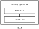
- FIG. 6 is a schematic block diagram of a wireless network-based positioning apparatus according to an embodiment of the present invention.
- the positioning apparatus 600 in FIG. 6 includes a receiver 610 and a processor 620.
- the receiver 610 is configured to obtain time information used for determining a current location of a to-be-positioned node, where the time information records times of arrival of a first sounding signal at at least three anchor nodes, and the first sounding signal is sent by the to-be-positioned node at the current location.
- the processor 620 is configured to: determine time differences of arrival of the first sounding signal at the at least three anchor nodes according to recorded historical information and the time information, where the time differences of arrival of the first sounding signal at the at least three anchor nodes are differences between the times of arrival of the first sounding signal at the at least three anchor nodes, the historical information records locations of the at least three anchor nodes, a historical location at which the to-be-positioned node sends a second sounding signal, and times of arrival of the second sounding signal at the at least three anchor nodes, and the second sounding signal is a sounding signal that is used for positioning and that is previously sent by the to-be-positioned node; and determine the current location of the to-be-positioned node according to the locations of the at least three anchor nodes and the time differences of arrival of the first sounding signal at the at least three anchor nodes.
- the time differences of arrival of the sounding signal, sent by the to-be-positioned node, at the different anchor nodes can be accurately determined according to the times of arrival of the sounding signal at the different anchor nodes and the historical information of the to-be-positioned node, thereby determining a location of the to-be-positioned node.
- accurate positioning can be performed by using TDOAs when the anchor nodes are asynchronous.
- the positioning apparatus 600 is the to-be-positioned node, and the positioning apparatus 600 further includes a transmitter; the transmitter is configured to send the first sounding signal to the at least three anchor nodes; and the receiver is specifically configured to receive the time information fed back by the at least three anchor nodes.
- the positioning apparatus 600 is a third-party device other than the to-be-positioned node, and the positioning apparatus 600 further includes a transmitter; the receiver 610 is specifically configured to receive the time information fed back by the at least three anchor nodes; and the transmitter is configured to send the determined current location to the to-be-positioned node.
- a time of arrival of the first sounding signal at any one of the at least three anchor nodes is estimated based on a time at which the any anchor node obtains the first sounding signal and a time period required for radio frequency processing and baseband processing of the any anchor node.
- wireless network-based positioning methods and positioning apparatuses in the embodiments of the present invention can be applied to not only a WLAN network but also all other asynchronous wireless networks.
- sequence numbers of the foregoing processes do not mean execution sequences in various embodiments of the present invention.
- the execution sequences of the processes should be determined according to functions and internal logic of the processes, and should not be construed as any limitation on the implementation processes of the embodiments of the present invention.
- the units described as separate parts may or may not be physically separate, and parts displayed as units may or may not be physical units, may be located in one position, or may be distributed on a plurality of network units. Some or all of the units may be selected according to actual requirements to achieve the objectives of the solutions of the embodiments.
- functional units in the embodiments of the present invention may be integrated into one processing unit, or each of the units may exist alone physically, or two or more units are integrated into one unit.
- the functions When the functions are implemented in the form of a software functional unit and sold or used as an independent product, the functions may be stored in a computer-readable storage medium.
- the software product is stored in a storage medium, and includes several instructions for instructing a computer device (which may be a personal computer, a server, or a network device) to perform all or some of the steps of the methods described in the embodiments of the present invention.
- the foregoing storage medium includes any medium that can store program code, such as a USB flash drive, a removable hard disk, a read-only memory (ROM), a random access memory (RAM), a magnetic disk, or an optical disc.
Landscapes
- Engineering & Computer Science (AREA)
- Computer Networks & Wireless Communication (AREA)
- Signal Processing (AREA)
- Physics & Mathematics (AREA)
- General Physics & Mathematics (AREA)
- Radar, Positioning & Navigation (AREA)
- Remote Sensing (AREA)
- Mobile Radio Communication Systems (AREA)
- Position Fixing By Use Of Radio Waves (AREA)
- Navigation (AREA)
Claims (12)
- Auf Drahtlosnetzwerk basierendes Positionierungsverfahren, umfassend:Erhalten (110) von Zeitinformationen, die zum Bestimmen einer aktuellen Position eines zu verortenden Knotens verwendet werden, wobei die Zeitinformationen Eintreffzeiten eines ersten Peilsignals an mindestens drei Ankerknoten aufzeichnen und das erste Peilsignal vom zu verortenden Knoten an der aktuellen Position gesendet wird;Bestimmen (120) von Zeitdifferenzen des Eintreffens des ersten Peilsignals an den mindestens drei Ankerknoten gemäß in historischen Informationen aufgezeichneten Positionen und den Zeitinformationen, wobei die Zeitdifferenzen des Eintreffens des ersten Peilsignals an den mindestens drei Ankerknoten Differenzen zwischen den Eintreffzeiten des ersten Peilsignals an den mindestens drei Ankerknoten, den in historischen Informationen aufgezeichneten Positionen der mindestens drei Ankerknoten, einer historischen Position, an der der zu verortende Knoten ein zweites Peilsignal gesendet hat, und Eintreffzeiten des zweiten Peilsignals an den mindestens drei Ankerknoten sind, und das zweite Peilsignal ein Peilsignal ist, das zur Positionierung verwendet wird und das vom zu verortenden Knoten gesendet wird, bevor der zu verortende Knoten das erste Peilsignal sendet; undBestimmen (130) der aktuellen Position des zu verortenden Knotens gemäß den Positionen der mindestens drei Ankerknoten und den Zeitdifferenzen des Eintreffens des ersten Peilsignals an den mindestens drei Ankerknoten.
- Positionierungsverfahren nach Anspruch 1, wobei das Bestimmen (120) von Zeitdifferenzen des Eintreffens des ersten Peilsignals an den mindestens drei Ankerknoten gemäß in historischen Informationen aufgezeichneten Positionen und den Zeitinformationen umfasst:Bestimmen von Entfernungen zwischen dem zu verortenden Knoten an der historischen Position und den mindestens drei Ankerknoten gemäß der historischen Position und den Positionen der mindestens drei Ankerknoten; undBestimmen einer Zeitdifferenz des Eintreffens des ersten Peilsignals an beliebigen zwei der mindestens drei Ankerknoten gemäß einer Formel
 wobei TAB die Zeitdifferenz des Eintreffens des ersten Peilsignals an den beliebigen zwei der mindestens drei Ankerknoten repräsentiert, c eine Ausbreitungsgeschwindigkeit eines Peilsignals repräsentiert, das vom zu verortenden Knoten gesendet wird, LA und LB jeweils Entfernungen zwischen der Position, an der der zu verortende Knoten das zweite Peilsignal sendet, und den zwei Ankerknoten repräsentieren, TA1 und TB1 jeweils Eintreffzeiten des zweiten Peilsignals an den zwei Ankerknoten repräsentieren und TA3 und TB3 jeweils Eintreffzeiten des ersten Peilsignals an den zwei Ankerknoten repräsentieren.
 - Positionierungsverfahren nach Anspruch 1 oder 2, wobei das Bestimmen (130) der aktuellen Position des zu verortenden Knotens gemäß den Positionen der mindestens drei Ankerknoten und den Zeitdifferenzen des Eintreffens des ersten Peilsignals an den mindestens drei Ankerknoten umfasst:Bestimmen der aktuellen Position des zu verortenden Knotens gemäß den folgenden Formeln:
 wobei (xA, yA), (xB, yB) und (xc, yc) jeweils Positionen eines ersten Ankerknotens, eines zweiten Ankerknotens und eines dritten Ankerknotens aus den mindestens drei Ankerknoten repräsentieren, TAB eine Zeitdifferenz des Eintreffens des ersten Peilsignals am ersten Ankerknoten und am zweiten Ankerknoten repräsentiert, TBC eine Zeitdifferenz des Eintreffens des ersten Peilsignals am zweiten Ankerknoten und am dritten Ankerknoten repräsentiert, (x, y) die aktuelle Position des zu verortenden Knotens repräsentiert und c die Ausbreitungsgeschwindigkeit des Peilsignals repräsentiert, das vom zu verortenden Knoten gesendet wird.
 - Positionierungsverfahren nach einem der Ansprüche 1 bis 3, wobei das Positionierungsverfahren vom zu verortenden Knoten durchgeführt wird und das Positionierungsverfahren ferner umfasst:Senden (301), durch den zu verortenden Knoten, des ersten Peilsignals an die mindestens drei Ankerknoten; undwobei das Erhalten (110) von Zeitinformationen, die zum Bestimmen einer aktuellen Position eines zu verortenden Knotens verwendet werden, umfasst:
Empfangen (302), durch den zu verortenden Knoten, der von den mindestens drei Ankerknoten zurückgemeldeten Zeitinformationen. - Positionierungsverfahren nach einem der Ansprüche 1 bis 3, wobei das Positionierungsverfahren von einem Fremdgerät durchgeführt wird, das nicht der zu verortende Knoten ist, und das Erhalten (110) von Zeitinformationen, die zum Bestimmen einer aktuellen Position eines zu verortenden Knotens verwendet werden, umfasst:Empfangen (402), durch das Fremdgerät, der von den mindestens drei Ankerknoten zurückgemeldeten Zeitinformationen; unddas Positionierungsverfahren ferner umfasst:
Senden (405), durch das Fremdgerät, der bestimmten aktuellen Position an den zu verortenden Knoten. - Positionierungsverfahren nach einem der Ansprüche 1 bis 5, wobei eine Eintreffzeit des ersten Peilsignals an einem beliebigen der mindestens drei Ankerknoten auf der Grundlage einer Zeit, zu der der beliebige Ankerknoten das erste Peilsignal erhält, und einer für die Hochfrequenzverarbeitung und die Basisbandverarbeitung des beliebigen Ankerknotens erforderlichen Zeitspanne berechnet wird.
- Auf Drahtlosnetzwerk basierende Positionierungsvorrichtung, umfassend:ein Erhaltemodul (510), das dafür ausgelegt ist, Zeitinformationen, die zum Bestimmen einer aktuellen Position eines zu verortenden Knotens verwendet werden, zu erhalten, wobei die Zeitinformationen dafür ausgelegt sind, Eintreffzeiten eines ersten Peilsignals an mindestens drei Ankerknoten aufzuzeichnen, und das erste Peilsignal vom zu verortenden Knoten an der aktuellen Position gesendet wird;ein erstes Bestimmungsmodul (520), das dafür ausgelegt ist, Zeitdifferenzen des Eintreffens des ersten Peilsignals an den mindestens drei Ankerknoten gemäß in historischen Informationen aufgezeichneten Positionen und den Zeitinformationen zu bestimmen, wobei die Zeitdifferenzen des Eintreffens des ersten Peilsignals an den mindestens drei Ankerknoten Differenzen zwischen den Eintreffzeiten des ersten Peilsignals an den mindestens drei Ankerknoten, den in historischen Informationen aufgezeichneten Positionen der mindestens drei Ankerknoten, einer historischen Position, an der der zu verortende Knoten ein zweites Peilsignal gesendet hat, und Eintreffzeiten des zweiten Peilsignals an den mindestens drei Ankerknoten sind, und das zweite Peilsignal ein Peilsignal ist, das zur Positionierung verwendet wird und das vom zu verortenden Knoten vorher gesendet wird; undein zweites Bestimmungsmodul (530), das dafür ausgelegt ist, die aktuelle Position des zu verortenden Knotens gemäß den Positionen der mindestens drei Ankerknoten und den Zeitdifferenzen des Eintreffens des ersten Peilsignals an den mindestens drei Ankerknoten zu bestimmen.
- Positionierungsvorrichtung nach Anspruch 7, wobei das erste Bestimmungsmodul (520) spezifisch für folgende Vorgänge ausgelegt ist:Bestimmen von Entfernungen zwischen dem zu verortenden Knoten an der historischen Position und den mindestens drei Ankerknoten gemäß der historischen Position und den Positionen der mindestens drei Ankerknoten; undBestimmen einer Zeitdifferenz des Eintreffens des ersten Peilsignals an beliebigen zwei der mindestens drei Ankerknoten gemäß einer Formel
 wobei TAB die Zeitdifferenz des Eintreffens des ersten Peilsignals an den beliebigen zwei der mindestens drei Ankerknoten repräsentiert, c eine Ausbreitungsgeschwindigkeit eines Peilsignals repräsentiert, das vom zu verortenden Knoten gesendet wird, LA und LB jeweils Entfernungen zwischen dem zu verortenden Knoten an der historischen Position und den zwei Ankerknoten repräsentieren, TA1 und TB1 jeweils Eintreffzeiten des zweiten Peilsignals an den zwei Ankerknoten repräsentieren und TA3 und TB3 jeweils Eintreffzeiten des ersten Peilsignals an den zwei Ankerknoten repräsentieren.
 - Positionierungsvorrichtung nach Anspruch 7 oder 8, wobei das zweite Bestimmungsmodul (530) spezifisch für folgende Vorgänge ausgelegt ist:Bestimmen der aktuellen Position des zu verortenden Knotens gemäß den folgenden Formeln:
 wobei (xA, yA), (xB, yB) und (xC, yC) jeweils Positionen eines ersten Ankerknotens, eines zweiten Ankerknotens und eines dritten Ankerknotens aus den mindestens drei Ankerknoten repräsentieren, TAB eine Zeitdifferenz des Eintreffens des ersten Peilsignals am ersten Ankerknoten und am zweiten Ankerknoten repräsentiert, TBC eine Zeitdifferenz des Eintreffens des ersten Peilsignals am zweiten Ankerknoten und am dritten Ankerknoten repräsentiert, (x, y) die aktuelle Position des zu verortenden Knotens repräsentiert und c die Ausbreitungsgeschwindigkeit des Peilsignals repräsentiert, das vom zu verortenden Knoten gesendet wird.
 - Positionierungsvorrichtung nach einem der Ansprüche 7 bis 9, wobei die Positionierungsvorrichtung der zu verortende Knoten ist und die Positionierungsvorrichtung ferner ein Sendemodul umfasst;das Sendemodul dafür ausgelegt ist, das erste Peilsignal an die mindestens drei Ankerknoten zu senden; unddas Erhaltemodul spezifisch dafür ausgelegt ist, die von den mindestens drei Ankerknoten zurückgemeldeten Zeitinformationen zu empfangen.
- Positionierungsvorrichtung nach einem der Ansprüche 7 bis 9, wobei die Positionierungsvorrichtung ein Fremdgerät ist, das nicht der zu verortende Knoten ist, und die Positionierungsvorrichtung ferner ein Sendemodul umfasst;das Erhaltemodul spezifisch dafür ausgelegt ist, die von den mindestens drei Ankerknoten zurückgemeldeten Zeitinformationen zu empfangen; unddas Sendemodul dafür ausgelegt ist, die bestimmte aktuelle Position an den zu verortenden Knoten zu senden.
- Positionierungsvorrichtung nach einem der Ansprüche 7 bis 11, wobei eine Eintreffzeit des ersten Peilsignals an einem der mindestens drei Ankerknoten auf der Grundlage einer Zeit, zu der der beliebige Ankerknoten das erste Peilsignal empfängt, und einer für die Hochfrequenzverarbeitung und die Basisbandverarbeitung des beliebigen Ankerknotens erforderlichen Zeitspanne berechnet wird.
Applications Claiming Priority (2)
| Application Number | Priority Date | Filing Date | Title |
|---|---|---|---|
| CN201510642053.8A CN106559870A (zh) | 2015-09-30 | 2015-09-30 | 基于无线网络的定位方法和定位装置 |
| PCT/CN2016/099820 WO2017054673A1 (zh) | 2015-09-30 | 2016-09-23 | 基于无线网络的定位方法和定位装置 |
Publications (3)
| Publication Number | Publication Date |
|---|---|
| EP3343959A1 EP3343959A1 (de) | 2018-07-04 |
| EP3343959A4 EP3343959A4 (de) | 2018-09-26 |
| EP3343959B1 true EP3343959B1 (de) | 2024-08-14 |
Family
ID=58417960
Family Applications (1)
| Application Number | Title | Priority Date | Filing Date |
|---|---|---|---|
| EP16850297.9A Active EP3343959B1 (de) | 2015-09-30 | 2016-09-23 | Auf drahtlosem netzwerk basiertes positionierungsverfahren und positionierungsvorrichtung |
Country Status (4)
| Country | Link |
|---|---|
| US (1) | US10191135B2 (de) |
| EP (1) | EP3343959B1 (de) |
| CN (1) | CN106559870A (de) |
| WO (1) | WO2017054673A1 (de) |
Families Citing this family (5)
| Publication number | Priority date | Publication date | Assignee | Title |
|---|---|---|---|---|
| CN107360623A (zh) * | 2017-06-01 | 2017-11-17 | 清华大学 | 无线网络中节点定位和同步方法及节点装置 |
| CN109525931B (zh) * | 2017-09-18 | 2021-10-29 | 中兴通讯股份有限公司 | 一种定位无线设备的方法、装置、设备及存储介质 |
| CN108469600B (zh) * | 2018-03-27 | 2020-06-30 | 清华大学 | 一种动态网络相对定位方法 |
| CN112153557B (zh) * | 2019-06-28 | 2022-03-25 | 上海华为技术有限公司 | 无线定位方法、定位装置和网络设备 |
| CN115494487B (zh) * | 2022-11-18 | 2023-03-24 | 成都太阳神鸟智能控制有限公司 | 一种无线定位测距方法 |
Family Cites Families (6)
| Publication number | Priority date | Publication date | Assignee | Title |
|---|---|---|---|---|
| US20040203870A1 (en) * | 2002-08-20 | 2004-10-14 | Daniel Aljadeff | Method and system for location finding in a wireless local area network |
| WO2004052027A2 (en) | 2002-11-27 | 2004-06-17 | Cognio, Inc | System and method for locating sources of unknown wireless radio signals |
| US8233457B1 (en) | 2009-09-03 | 2012-07-31 | Qualcomm Atheros, Inc. | Synchronization-free station locator in wireless network |
| CN102455421B (zh) * | 2010-10-27 | 2014-03-26 | 清华大学 | 无需时间同步的声音定位系统及方法 |
| US8687560B2 (en) | 2011-11-01 | 2014-04-01 | Diani Systems, Inc. | Unsynchronized time-of-flight-based wireless positioning system using network broadcasts |
| CN103561387A (zh) * | 2013-11-11 | 2014-02-05 | 无锡清华信息科学与技术国家实验室物联网技术中心 | 一种基于TDoA的室内定位方法及系统 |
-
2015
- 2015-09-30 CN CN201510642053.8A patent/CN106559870A/zh active Pending
-
2016
- 2016-09-23 WO PCT/CN2016/099820 patent/WO2017054673A1/zh not_active Ceased
- 2016-09-23 EP EP16850297.9A patent/EP3343959B1/de active Active
-
2018
- 2018-03-30 US US15/942,145 patent/US10191135B2/en active Active
Also Published As
| Publication number | Publication date |
|---|---|
| US20180246184A1 (en) | 2018-08-30 |
| EP3343959A1 (de) | 2018-07-04 |
| WO2017054673A1 (zh) | 2017-04-06 |
| EP3343959A4 (de) | 2018-09-26 |
| CN106559870A (zh) | 2017-04-05 |
| US10191135B2 (en) | 2019-01-29 |
Similar Documents
| Publication | Publication Date | Title |
|---|---|---|
| US10306408B2 (en) | Positioning method, positioning server, and positioning system | |
| US10595292B2 (en) | Asynchronous wireless communication system | |
| EP3343959B1 (de) | Auf drahtlosem netzwerk basiertes positionierungsverfahren und positionierungsvorrichtung | |
| US10104634B2 (en) | Method and apparatus for performing a passive indoor localization of a mobile endpoint device | |
| Smith et al. | Tracking moving devices with the cricket location system | |
| CN104205964B (zh) | 移动地理定位 | |
| US8848565B2 (en) | Method for performing measurements and positioning in a network based WLAN positioning system | |
| US8837316B2 (en) | RTT based ranging system and method | |
| JP5980929B2 (ja) | 到来時間に基づく測位システム | |
| EP2769233B1 (de) | Drahtloses positionierungssystem auf ankunftszeitbasis | |
| CN113676830B (zh) | 一种信息上报方法、装置、设备及可读存储介质 | |
| US8489114B2 (en) | Time difference of arrival based positioning system | |
| WO2017113072A1 (zh) | 基于到达时间差定位方法、用户设备及网络设备 | |
| US20170339527A9 (en) | Method and Apparatus for Indoor Location Estimation Among Peer-To-Peer Devices | |
| US20180329023A1 (en) | System and method for wireless time-of-arrival localization | |
| Kolakowski et al. | TDOA-TWR based positioning algorithm for UWB localization system | |
| US20160337808A1 (en) | Method and Apparatus for Indoor Location Estimation Among Peer-To-Peer Devices | |
| WO2013043664A1 (en) | Hybrid positioning system based on time difference of arrival (tdoa) and time of arrival (toa) | |
| JP2011158459A (ja) | パターン分類を使用した、無線端末が屋内にあるかどうかの推定 | |
| US20200145790A1 (en) | Positioning correction method and apparatus | |
| US20170269190A1 (en) | Improving Accuracy when Determining Positions in a Wireless Network | |
| CN106507471A (zh) | 无线通信系统中的定位增强方法、装置及系统 | |
| JP2015507172A (ja) | 距離推定 | |
| JP5075396B2 (ja) | 位置推定方法および位置推定システム | |
| JP7814732B2 (ja) | 位置推定装置、位置推定システムおよび移動ノード |
Legal Events
| Date | Code | Title | Description |
|---|---|---|---|
| STAA | Information on the status of an ep patent application or granted ep patent |
Free format text: STATUS: THE INTERNATIONAL PUBLICATION HAS BEEN MADE |
|
| PUAI | Public reference made under article 153(3) epc to a published international application that has entered the european phase |
Free format text: ORIGINAL CODE: 0009012 |
|
| STAA | Information on the status of an ep patent application or granted ep patent |
Free format text: STATUS: REQUEST FOR EXAMINATION WAS MADE |
|
| 17P | Request for examination filed |
Effective date: 20180329 |
|
| AK | Designated contracting states |
Kind code of ref document: A1 Designated state(s): AL AT BE BG CH CY CZ DE DK EE ES FI FR GB GR HR HU IE IS IT LI LT LU LV MC MK MT NL NO PL PT RO RS SE SI SK SM TR |
|
| AX | Request for extension of the european patent |
Extension state: BA ME |
|
| A4 | Supplementary search report drawn up and despatched |
Effective date: 20180829 |
|
| RIC1 | Information provided on ipc code assigned before grant |
Ipc: G01S 5/06 20060101AFI20180823BHEP |
|
| DAV | Request for validation of the european patent (deleted) | ||
| DAX | Request for extension of the european patent (deleted) | ||
| STAA | Information on the status of an ep patent application or granted ep patent |
Free format text: STATUS: EXAMINATION IS IN PROGRESS |
|
| 17Q | First examination report despatched |
Effective date: 20200318 |
|
| GRAP | Despatch of communication of intention to grant a patent |
Free format text: ORIGINAL CODE: EPIDOSNIGR1 |
|
| STAA | Information on the status of an ep patent application or granted ep patent |
Free format text: STATUS: GRANT OF PATENT IS INTENDED |
|
| RIC1 | Information provided on ipc code assigned before grant |
Ipc: G01S 5/06 20060101ALI20220223BHEP Ipc: G01S 5/02 20100101AFI20220223BHEP |
|
| INTG | Intention to grant announced |
Effective date: 20220309 |
|
| GRAS | Grant fee paid |
Free format text: ORIGINAL CODE: EPIDOSNIGR3 |
|
| GRAJ | Information related to disapproval of communication of intention to grant by the applicant or resumption of examination proceedings by the epo deleted |
Free format text: ORIGINAL CODE: EPIDOSDIGR1 |
|
| GRAL | Information related to payment of fee for publishing/printing deleted |
Free format text: ORIGINAL CODE: EPIDOSDIGR3 |
|
| STAA | Information on the status of an ep patent application or granted ep patent |
Free format text: STATUS: EXAMINATION IS IN PROGRESS |
|
| INTC | Intention to grant announced (deleted) | ||
| RIN1 | Information on inventor provided before grant (corrected) |
Inventor name: YANG, HUI Inventor name: JIANG, YANPING Inventor name: YANG, XUN |
|
| REG | Reference to a national code |
Ref legal event code: R079 Ref country code: DE Ref document number: 602016088925 Country of ref document: DE Free format text: PREVIOUS MAIN CLASS: H04W0004020000 Ipc: G01S0005020000 |
|
| GRAP | Despatch of communication of intention to grant a patent |
Free format text: ORIGINAL CODE: EPIDOSNIGR1 |
|
| STAA | Information on the status of an ep patent application or granted ep patent |
Free format text: STATUS: GRANT OF PATENT IS INTENDED |
|
| INTG | Intention to grant announced |
Effective date: 20240311 |
|
| RIC1 | Information provided on ipc code assigned before grant |
Ipc: G01S 5/06 20060101ALI20240226BHEP Ipc: G01S 5/02 20100101AFI20240226BHEP |
|
| GRAS | Grant fee paid |
Free format text: ORIGINAL CODE: EPIDOSNIGR3 |
|
| GRAA | (expected) grant |
Free format text: ORIGINAL CODE: 0009210 |
|
| STAA | Information on the status of an ep patent application or granted ep patent |
Free format text: STATUS: THE PATENT HAS BEEN GRANTED |
|
| AK | Designated contracting states |
Kind code of ref document: B1 Designated state(s): AL AT BE BG CH CY CZ DE DK EE ES FI FR GB GR HR HU IE IS IT LI LT LU LV MC MK MT NL NO PL PT RO RS SE SI SK SM TR |
|
| REG | Reference to a national code |
Ref country code: GB Ref legal event code: FG4D |
|
| REG | Reference to a national code |
Ref country code: CH Ref legal event code: EP |
|
| REG | Reference to a national code |
Ref country code: DE Ref legal event code: R096 Ref document number: 602016088925 Country of ref document: DE |
|
| REG | Reference to a national code |
Ref country code: IE Ref legal event code: FG4D |
|
| REG | Reference to a national code |
Ref country code: LT Ref legal event code: MG9D |
|
| REG | Reference to a national code |
Ref country code: NL Ref legal event code: MP Effective date: 20240814 |
|
| PG25 | Lapsed in a contracting state [announced via postgrant information from national office to epo] |
Ref country code: NO Free format text: LAPSE BECAUSE OF FAILURE TO SUBMIT A TRANSLATION OF THE DESCRIPTION OR TO PAY THE FEE WITHIN THE PRESCRIBED TIME-LIMIT Effective date: 20241114 |
|
| REG | Reference to a national code |
Ref country code: AT Ref legal event code: MK05 Ref document number: 1713785 Country of ref document: AT Kind code of ref document: T Effective date: 20240814 |
|
| PG25 | Lapsed in a contracting state [announced via postgrant information from national office to epo] |
Ref country code: GR Free format text: LAPSE BECAUSE OF FAILURE TO SUBMIT A TRANSLATION OF THE DESCRIPTION OR TO PAY THE FEE WITHIN THE PRESCRIBED TIME-LIMIT Effective date: 20241115 Ref country code: PL Free format text: LAPSE BECAUSE OF FAILURE TO SUBMIT A TRANSLATION OF THE DESCRIPTION OR TO PAY THE FEE WITHIN THE PRESCRIBED TIME-LIMIT Effective date: 20240814 Ref country code: FI Free format text: LAPSE BECAUSE OF FAILURE TO SUBMIT A TRANSLATION OF THE DESCRIPTION OR TO PAY THE FEE WITHIN THE PRESCRIBED TIME-LIMIT Effective date: 20240814 Ref country code: NL Free format text: LAPSE BECAUSE OF FAILURE TO SUBMIT A TRANSLATION OF THE DESCRIPTION OR TO PAY THE FEE WITHIN THE PRESCRIBED TIME-LIMIT Effective date: 20240814 Ref country code: PT Free format text: LAPSE BECAUSE OF FAILURE TO SUBMIT A TRANSLATION OF THE DESCRIPTION OR TO PAY THE FEE WITHIN THE PRESCRIBED TIME-LIMIT Effective date: 20241216 |
|
| PG25 | Lapsed in a contracting state [announced via postgrant information from national office to epo] |
Ref country code: BG Free format text: LAPSE BECAUSE OF FAILURE TO SUBMIT A TRANSLATION OF THE DESCRIPTION OR TO PAY THE FEE WITHIN THE PRESCRIBED TIME-LIMIT Effective date: 20240814 |
|
| PG25 | Lapsed in a contracting state [announced via postgrant information from national office to epo] |
Ref country code: LV Free format text: LAPSE BECAUSE OF FAILURE TO SUBMIT A TRANSLATION OF THE DESCRIPTION OR TO PAY THE FEE WITHIN THE PRESCRIBED TIME-LIMIT Effective date: 20240814 |
|
| PG25 | Lapsed in a contracting state [announced via postgrant information from national office to epo] |
Ref country code: AT Free format text: LAPSE BECAUSE OF FAILURE TO SUBMIT A TRANSLATION OF THE DESCRIPTION OR TO PAY THE FEE WITHIN THE PRESCRIBED TIME-LIMIT Effective date: 20240814 Ref country code: IS Free format text: LAPSE BECAUSE OF FAILURE TO SUBMIT A TRANSLATION OF THE DESCRIPTION OR TO PAY THE FEE WITHIN THE PRESCRIBED TIME-LIMIT Effective date: 20241214 |
|
| PG25 | Lapsed in a contracting state [announced via postgrant information from national office to epo] |
Ref country code: HR Free format text: LAPSE BECAUSE OF FAILURE TO SUBMIT A TRANSLATION OF THE DESCRIPTION OR TO PAY THE FEE WITHIN THE PRESCRIBED TIME-LIMIT Effective date: 20240814 |
|
| PG25 | Lapsed in a contracting state [announced via postgrant information from national office to epo] |
Ref country code: RS Free format text: LAPSE BECAUSE OF FAILURE TO SUBMIT A TRANSLATION OF THE DESCRIPTION OR TO PAY THE FEE WITHIN THE PRESCRIBED TIME-LIMIT Effective date: 20241114 Ref country code: ES Free format text: LAPSE BECAUSE OF FAILURE TO SUBMIT A TRANSLATION OF THE DESCRIPTION OR TO PAY THE FEE WITHIN THE PRESCRIBED TIME-LIMIT Effective date: 20240814 |
|
| PG25 | Lapsed in a contracting state [announced via postgrant information from national office to epo] |
Ref country code: RS Free format text: LAPSE BECAUSE OF FAILURE TO SUBMIT A TRANSLATION OF THE DESCRIPTION OR TO PAY THE FEE WITHIN THE PRESCRIBED TIME-LIMIT Effective date: 20241114 Ref country code: PT Free format text: LAPSE BECAUSE OF FAILURE TO SUBMIT A TRANSLATION OF THE DESCRIPTION OR TO PAY THE FEE WITHIN THE PRESCRIBED TIME-LIMIT Effective date: 20241216 Ref country code: PL Free format text: LAPSE BECAUSE OF FAILURE TO SUBMIT A TRANSLATION OF THE DESCRIPTION OR TO PAY THE FEE WITHIN THE PRESCRIBED TIME-LIMIT Effective date: 20240814 Ref country code: NO Free format text: LAPSE BECAUSE OF FAILURE TO SUBMIT A TRANSLATION OF THE DESCRIPTION OR TO PAY THE FEE WITHIN THE PRESCRIBED TIME-LIMIT Effective date: 20241114 Ref country code: NL Free format text: LAPSE BECAUSE OF FAILURE TO SUBMIT A TRANSLATION OF THE DESCRIPTION OR TO PAY THE FEE WITHIN THE PRESCRIBED TIME-LIMIT Effective date: 20240814 Ref country code: LV Free format text: LAPSE BECAUSE OF FAILURE TO SUBMIT A TRANSLATION OF THE DESCRIPTION OR TO PAY THE FEE WITHIN THE PRESCRIBED TIME-LIMIT Effective date: 20240814 Ref country code: IS Free format text: LAPSE BECAUSE OF FAILURE TO SUBMIT A TRANSLATION OF THE DESCRIPTION OR TO PAY THE FEE WITHIN THE PRESCRIBED TIME-LIMIT Effective date: 20241214 Ref country code: HR Free format text: LAPSE BECAUSE OF FAILURE TO SUBMIT A TRANSLATION OF THE DESCRIPTION OR TO PAY THE FEE WITHIN THE PRESCRIBED TIME-LIMIT Effective date: 20240814 Ref country code: GR Free format text: LAPSE BECAUSE OF FAILURE TO SUBMIT A TRANSLATION OF THE DESCRIPTION OR TO PAY THE FEE WITHIN THE PRESCRIBED TIME-LIMIT Effective date: 20241115 Ref country code: FI Free format text: LAPSE BECAUSE OF FAILURE TO SUBMIT A TRANSLATION OF THE DESCRIPTION OR TO PAY THE FEE WITHIN THE PRESCRIBED TIME-LIMIT Effective date: 20240814 Ref country code: ES Free format text: LAPSE BECAUSE OF FAILURE TO SUBMIT A TRANSLATION OF THE DESCRIPTION OR TO PAY THE FEE WITHIN THE PRESCRIBED TIME-LIMIT Effective date: 20240814 Ref country code: BG Free format text: LAPSE BECAUSE OF FAILURE TO SUBMIT A TRANSLATION OF THE DESCRIPTION OR TO PAY THE FEE WITHIN THE PRESCRIBED TIME-LIMIT Effective date: 20240814 Ref country code: AT Free format text: LAPSE BECAUSE OF FAILURE TO SUBMIT A TRANSLATION OF THE DESCRIPTION OR TO PAY THE FEE WITHIN THE PRESCRIBED TIME-LIMIT Effective date: 20240814 |
|
| PG25 | Lapsed in a contracting state [announced via postgrant information from national office to epo] |
Ref country code: SM Free format text: LAPSE BECAUSE OF FAILURE TO SUBMIT A TRANSLATION OF THE DESCRIPTION OR TO PAY THE FEE WITHIN THE PRESCRIBED TIME-LIMIT Effective date: 20240814 Ref country code: RO Free format text: LAPSE BECAUSE OF FAILURE TO SUBMIT A TRANSLATION OF THE DESCRIPTION OR TO PAY THE FEE WITHIN THE PRESCRIBED TIME-LIMIT Effective date: 20240814 Ref country code: DK Free format text: LAPSE BECAUSE OF FAILURE TO SUBMIT A TRANSLATION OF THE DESCRIPTION OR TO PAY THE FEE WITHIN THE PRESCRIBED TIME-LIMIT Effective date: 20240814 |
|
| PG25 | Lapsed in a contracting state [announced via postgrant information from national office to epo] |
Ref country code: EE Free format text: LAPSE BECAUSE OF FAILURE TO SUBMIT A TRANSLATION OF THE DESCRIPTION OR TO PAY THE FEE WITHIN THE PRESCRIBED TIME-LIMIT Effective date: 20240814 |
|
| PG25 | Lapsed in a contracting state [announced via postgrant information from national office to epo] |
Ref country code: CZ Free format text: LAPSE BECAUSE OF FAILURE TO SUBMIT A TRANSLATION OF THE DESCRIPTION OR TO PAY THE FEE WITHIN THE PRESCRIBED TIME-LIMIT Effective date: 20240814 |
|
| PG25 | Lapsed in a contracting state [announced via postgrant information from national office to epo] |
Ref country code: IT Free format text: LAPSE BECAUSE OF FAILURE TO SUBMIT A TRANSLATION OF THE DESCRIPTION OR TO PAY THE FEE WITHIN THE PRESCRIBED TIME-LIMIT Effective date: 20240814 Ref country code: SK Free format text: LAPSE BECAUSE OF FAILURE TO SUBMIT A TRANSLATION OF THE DESCRIPTION OR TO PAY THE FEE WITHIN THE PRESCRIBED TIME-LIMIT Effective date: 20240814 |
|
| REG | Reference to a national code |
Ref country code: CH Ref legal event code: PL |
|
| REG | Reference to a national code |
Ref country code: DE Ref legal event code: R097 Ref document number: 602016088925 Country of ref document: DE |
|
| PG25 | Lapsed in a contracting state [announced via postgrant information from national office to epo] |
Ref country code: LU Free format text: LAPSE BECAUSE OF NON-PAYMENT OF DUE FEES Effective date: 20240923 |
|
| PLBE | No opposition filed within time limit |
Free format text: ORIGINAL CODE: 0009261 |
|
| STAA | Information on the status of an ep patent application or granted ep patent |
Free format text: STATUS: NO OPPOSITION FILED WITHIN TIME LIMIT |
|
| PG25 | Lapsed in a contracting state [announced via postgrant information from national office to epo] |
Ref country code: MC Free format text: LAPSE BECAUSE OF FAILURE TO SUBMIT A TRANSLATION OF THE DESCRIPTION OR TO PAY THE FEE WITHIN THE PRESCRIBED TIME-LIMIT Effective date: 20240814 |
|
| REG | Reference to a national code |
Ref country code: BE Ref legal event code: MM Effective date: 20240930 |
|
| PG25 | Lapsed in a contracting state [announced via postgrant information from national office to epo] |
Ref country code: BE Free format text: LAPSE BECAUSE OF NON-PAYMENT OF DUE FEES Effective date: 20240930 |
|
| 26N | No opposition filed |
Effective date: 20250515 |
|
| PG25 | Lapsed in a contracting state [announced via postgrant information from national office to epo] |
Ref country code: CH Free format text: LAPSE BECAUSE OF NON-PAYMENT OF DUE FEES Effective date: 20240930 |
|
| PG25 | Lapsed in a contracting state [announced via postgrant information from national office to epo] |
Ref country code: IE Free format text: LAPSE BECAUSE OF NON-PAYMENT OF DUE FEES Effective date: 20240923 |
|
| PG25 | Lapsed in a contracting state [announced via postgrant information from national office to epo] |
Ref country code: SE Free format text: LAPSE BECAUSE OF FAILURE TO SUBMIT A TRANSLATION OF THE DESCRIPTION OR TO PAY THE FEE WITHIN THE PRESCRIBED TIME-LIMIT Effective date: 20240814 |
|
| PGFP | Annual fee paid to national office [announced via postgrant information from national office to epo] |
Ref country code: DE Payment date: 20250730 Year of fee payment: 10 |
|
| PGFP | Annual fee paid to national office [announced via postgrant information from national office to epo] |
Ref country code: GB Payment date: 20250731 Year of fee payment: 10 |
|
| PGFP | Annual fee paid to national office [announced via postgrant information from national office to epo] |
Ref country code: FR Payment date: 20250808 Year of fee payment: 10 |
|
| PG25 | Lapsed in a contracting state [announced via postgrant information from national office to epo] |
Ref country code: CY Free format text: LAPSE BECAUSE OF FAILURE TO SUBMIT A TRANSLATION OF THE DESCRIPTION OR TO PAY THE FEE WITHIN THE PRESCRIBED TIME-LIMIT; INVALID AB INITIO Effective date: 20160923 |
|
| PG25 | Lapsed in a contracting state [announced via postgrant information from national office to epo] |
Ref country code: HU Free format text: LAPSE BECAUSE OF FAILURE TO SUBMIT A TRANSLATION OF THE DESCRIPTION OR TO PAY THE FEE WITHIN THE PRESCRIBED TIME-LIMIT; INVALID AB INITIO Effective date: 20160923 |