EP3343942A1 - Speaker system for moving body and moving body - Google Patents
Speaker system for moving body and moving body Download PDFInfo
- Publication number
- EP3343942A1 EP3343942A1 EP15902930.5A EP15902930A EP3343942A1 EP 3343942 A1 EP3343942 A1 EP 3343942A1 EP 15902930 A EP15902930 A EP 15902930A EP 3343942 A1 EP3343942 A1 EP 3343942A1
- Authority
- EP
- European Patent Office
- Prior art keywords
- mobile object
- door
- tubular member
- vehicle
- speaker unit
- Prior art date
- Legal status (The legal status is an assumption and is not a legal conclusion. Google has not performed a legal analysis and makes no representation as to the accuracy of the status listed.)
- Granted
Links
Images


Classifications
-
- B—PERFORMING OPERATIONS; TRANSPORTING
- B60—VEHICLES IN GENERAL
- B60R—VEHICLES, VEHICLE FITTINGS, OR VEHICLE PARTS, NOT OTHERWISE PROVIDED FOR
- B60R11/00—Arrangements for holding or mounting articles, not otherwise provided for
- B60R11/02—Arrangements for holding or mounting articles, not otherwise provided for for radio sets, television sets, telephones, or the like; Arrangement of controls thereof
- B60R11/0217—Arrangements for holding or mounting articles, not otherwise provided for for radio sets, television sets, telephones, or the like; Arrangement of controls thereof for loud-speakers
-
- H—ELECTRICITY
- H04—ELECTRIC COMMUNICATION TECHNIQUE
- H04R—LOUDSPEAKERS, MICROPHONES, GRAMOPHONE PICK-UPS OR LIKE ACOUSTIC ELECTROMECHANICAL TRANSDUCERS; ELECTRIC HEARING AIDS; PUBLIC ADDRESS SYSTEMS
- H04R1/00—Details of transducers, loudspeakers or microphones
- H04R1/02—Casings; Cabinets ; Supports therefor; Mountings therein
-
- B—PERFORMING OPERATIONS; TRANSPORTING
- B60—VEHICLES IN GENERAL
- B60R—VEHICLES, VEHICLE FITTINGS, OR VEHICLE PARTS, NOT OTHERWISE PROVIDED FOR
- B60R11/00—Arrangements for holding or mounting articles, not otherwise provided for
- B60R2011/0001—Arrangements for holding or mounting articles, not otherwise provided for characterised by position
- B60R2011/0003—Arrangements for holding or mounting articles, not otherwise provided for characterised by position inside the vehicle
- B60R2011/0019—Side or rear panels
- B60R2011/0021—Doors
Definitions
- the present invention relates to a speaker system for a mobile object and a mobile object.
- an on-vehicle speaker device (a speaker system for a mobile object) which is placed in an instrument panel and utilizes sound emitted from a back side (for example, see Patent Literature 1).
- a speaker is installed in an instrument panel with its front side set at an upper surface of the instrument panel and is accommodated in a cylindrical acoustic tube (a tubular member).
- the speaker device is configured such that a component of a low sound range in the sound generated at the back side of the speaker resonates in the acoustic tube and is emitted from a lower surface of the instrument panel.
- Patent Document 1 Japanese Unexamined Utility Model Application Publication No. H1-143595
- Patent Literature 1 the on-vehicle speaker device described in Patent Literature 1 was not able to improve the acoustic characteristics of the low sound range sufficiently since sound emitted from the acoustic tube did not echo easily in a space in a vehicle.
- an object of the invention is to provide a speaker system for a mobile object which is capable of improving the acoustic characteristics of the low sound range.
- a speaker system for a mobile object of the present invention includes: a speaker unit emitting sound from a front side toward a box-shaped space formed by the mobile object having a vehicle body a door installed on the vehicle body; an accommodating unit accommodating the back side of the speaker unit; and a tubular member having one end connected to an internal space of the accommodating unit, and the other end of the tubular member is opening toward a gap between a lower end part of the door and a part of the vehicle body confronting the lower end part of the door.
- a speaker system for a mobile object includes: a speaker unit emitting sound from the front side toward a box-shaped space formed by the mobile object having an vehicle body and a door installed on the vehicle body; an accommodating unit accommodating the back side of the speaker unit; and a tubular member having one end connected to an internal space of the accommodating unit, and the other end of the tubular member opens toward a gap between a lower end part of the door and a part of the vehicle body confronting the lower end part of the door.
- the accommodating unit a space to accommodate the speaker unit
- a component of the low sound range corresponding to a length of the tubular member among sounds generated at the back side of the speaker unit resonates in the tubular member and is emitted from the other end.
- the accommodating unit and the tubular member may be formed integrally.
- the other end of the tubular member opens toward the gap between a lower surface of the door and the part of the vehicle body, the component of the low sound range emitted from the other end is reflected on two surfaces of the lower surface of the door which forms the gap and a surface of the part of the vehicle body.
- the component of the low sound range tends to echo in the space of the mobile object, and the acoustic characteristics such as sound pressure of the low sound range of the speaker system for the mobile object may be improved.
- the other end of the tubular member preferably opens toward the part of the vehicle body which forms the gap.
- the component of the low sound range emitted from the other end is reflected on the two surfaces of the lower surface of the door which forms the gap and the surface of the part of the vehicle body.
- the component of the low sound range tends to echo in the space of the mobile object, and the acoustic characteristics such as sound pressure of the low sound range of the speaker system for the mobile object can be improved.
- a length of the gap in a vertical direction of the door is preferably formed as to get larger toward an inner side of the box-shaped space (for example, a location where a seat is installed).
- flair effect occurs. Then, it may result in reducing a wind noise or turbulence of the air flow.
- the component of the low sound range emitted from the other end of the tubular member reflects on the two surfaces of the lower surface of the door which forms the gap and the surface of the part of the vehicle body and echoes easily in the space of mobile object and the acoustic characteristics such as sound pressure of the low sound range of the speaker system for the mobile object may be improved.
- the speaker unit is installed on the door in order to emit sound from the front side toward the space and also is installed above a seat surface of the seat mounted in the mobile object and that the tubular member is located inside the door and also extends in the vertical direction of the door. Since the speaker unit is installed above the seat surface of the seat mounted in the mobile object, it is possible for emitted sound (especially, a middle and high sound range) to reach a passenger easily. Further, the other end of the tubular member lies inside the door, resulting in extending to the lower part of the door, and thus it is possible to improve the acoustic characteristics such as sound pressure of the low sound range.
- the mobile object according to the embodiment of the present invention is provided with the speaker system for the mobile object, and the one end of the tubular member is connected to the internal space of the accommodating unit (the space to accommodate the speaker unit), the component of the low sound range corresponding to the length of the tubular member among the sounds generated at the back side of the speaker unit resonates in the tubular member and is emitted from the other end.
- the accommodating unit and the tubular member may be formed integrally.
- the other end of the tubular member is opening toward the gap between the lower surface of the door and the part of the vehicle body, the component of the low sound range emitted from the other end is reflected on the two surfaces of the lower surface of the door which forms the gap and the surface of the part of the vehicle body.
- the component of the low sound range tends to echo in the space of the mobile object, and the acoustic characteristics such as sound pressure of the low sound range of the speaker system for the mobile object may be improved.
- FIG. 1 is a side view illustrating a mobile object installed with a speaker system for a mobile object of the present invention.
- FIG. 2 is a side view illustrating a part of a mobile object illustrated in FIG. 1 .
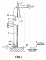
- FIG. 3 is a cross-sectional view taken along line I-I of FIG. 2 .
- a speaker system for a mobile object 1 includes, as illustrated in FIGS. 1 and 2 , a speaker unit 2 installed in a vehicle C (a mobile object), an enclosure 3 (an accommodating unit) which accommodates the speaker unit 2, and a tubular member 4 connected to the enclosure 3.
- the vehicle C forms a box-shaped room space of the vehicle A1 (a space) surrounded by a not-sown inner surface of a windshield, an upper surface (a top surface) S1 of an vehicle body B, a lower surface (a bottom face) S2, a front surface S3 which is located on the front side in a travelling direction of the vehicle C, a pair of side surfaces S4 (including a door body such as a vehicle door D) confronting each other in a width direction (a crosswise direction), and a back surface (not shown on the diagram) on the back side in the travelling direction of the vehicle C.
- an instrument panel I is provided on the front surface S3, front seats (a driver's seat and a passenger seat) are provided confronting the back side of the instrument panel I, and back seats are provided on the back side of the front seats.
- a seat on the passenger seat side is omitted, and the seat on the driver seat side is marked with "SH".
- the speaker system for the mobile object 1 is provided in a vehicle door D, D1 (as illustrated in FIG. 2 ) which is located in the width direction of the driver's seat, but it also may be provided in a vehicle door D, D2 (as illustrated in FIG. 1 ) on the passenger seat side, or it also may be provided in the both doors.
- the speaker system for the mobile object 1 may be provided in a vehicle door D, D3 (as illustrated in FIG. 1 ) of the seat at the back side, and it also may be provided in a back door D, D4 (as illustrated in FIG. 1 ) confronting the front surface S3.
- the present invention may be applied to any vehicle door D on the vehicle C.
- the vehicle C is configured to include the vehicle body B configuring a skeleton and the vehicle door D installed on a frame which is a part of the vehicle body B.
- the vehicle body B may have a panel and the frame (a hollow frame), and a monocoque body and the like are mentioned for example.
- the vehicle door D is configured to include a metal outer panel P1 which is a vehicle exterior member and an inner panel P2 made of a synthetic resin which is a vehicle interior member.
- a window frame F is provided on the outer panel P1, and an opening of the window frame F is opened/closed by a lifting glass G.
- the inner panel P2 is provided overlapping the outer panel P1 with an upper end of the inner panel P2 joined to a lower end part of the window frame F.
- the flame is formed in a flame-like shape composed of an upper end, a lower end (a side sill SS), a front end, and a back end surrounding the vehicle door D.
- a part which forms the lower end part is indicated as the side sill SS.
- a gap K which is a part of the room space of the vehicle A1 between a lower surface Da (the lower end of the vehicle door D) of the inner panel P2 of the vehicle door D and the side sill SS.
- a sound wave is emitted from the gap K to the room space of the vehicle A1. That is, a later-described other end 4B of the tubular member 4 is opening toward the gap K.
- the other end 4B of the tubular member 4 is opening on the lower surface Da of the inner panel P2, but the present invention is not limited to this case.
- the other end of the tubular member may be opening on a lower surface of the outer panel P1.
- the gap K is formed between the lower surface Da of the inner panel P2 of the vehicle door D and the side sill SS, and the length of the gap K in the vertical direction of the vehicle door D is formed to become gradually larger as getting closer to the room space of the vehicle A1.
- the gap K is formed of a slope where a distance from the lower surface Da of the inner panel P2 to the side sill SS becomes larger as getting closer to the room space of the vehicle A1.
- the side sill SS may have a slope where the distance in the vertical direction from the lower surface Da of the inner panel P2 becomes larger as getting closer to the room space of the vehicle Al, or both parts which form the gap K may have the slope each.
- the gap K is formed to become gradually larger as getting closer to the room space of the vehicle A1. That is, since the length of the gap in the vertical direction of the vehicle door D increases toward the inner side of the box-shaped room space of the vehicle Al, flair effect occurs and it may result in reducing a wind noise or turbulence of the air flow. Further, the component of the low sound range emitted from the other end 4B of the tubular member 4 reflects on the two surfaces of the lower surface Da of the vehicle door D which forms the gap K and the side sill SS of the vehicle body B and echoes easily in the room space of the vehicle A1 of the vehicle C and the acoustic characteristics such as sound pressure of the low sound range of the speaker system for the mobile object 1 is improved.
- the speaker unit 2 is provided above and in front of the inner panel P2. That is, the speaker unit 2 is installed to be located above a seat surface S of the seat SH mounted in the vehicle C (the mobile object).
- This speaker unit 2 includes a vibration plate, a voice coil connected to the vibration plate, an edge which supports the vibration plate, a magnetic circuit which vibrates the voice coil, a flame which supports the edge and the magnetic circuit, and a damper which supports the voice coil supported by the vibration plate.
- the speaker unit 2 may emit the sound wave to make sound pressure of the middle and high sound range (for example, 1000 Hz to 10000 Hz) higher than that of the low sound range (for example, 10 Hz to 1000 Hz).
- the vibration plate is provided with a side from which the speaker unit 2 emits the sound wave (the front surface S3) facing one side in the width direction (the driver's seat side or the passenger seat side) and also with the magnetic circuit side (the back side) facing the other side in the width direction.
- the speaker unit 2 may be provided on the inner surface of the vehicle door D so that a vibration direction (a sound emission direction) of the vibration plate of the speaker unit 2 inclines at a predetermined degree (for example, 30 degrees) against the inner surface of the vehicle door D.
- the vibration direction (the sound emission direction) of the vibration plate of the speaker unit 2 against the inner surface of the vehicle door D may be set appropriately according to the distance between the speaker unit 2 and the seat SH or the like, and in such a case, a central axis or the vibration plate of the speaker unit 2 may not be inclined. Further, the central axis or the vibration plate of the speaker unit 2 may be set to face a headrest of the vehicle door D on which the speaker unit 2 is provided. Setting the speaker unit 2 in such a direction may make the sound wave (especially the middle and high sound range) emitted from the speaker unit 2 reach the passenger more easily.
- the enclosure 3 is formed in a box-shape and is also provided in the inner panel P2 of the vehicle door D, on a top surface 30 of which the vibration plate is placed, and has the speaker unit 2 placed in the internal space thereof formed by the bottom surface 31 (as illustrated in FIG. 3 ) and four sides 32, 33, 34, and 35, and thus accommodating therein the back side of the speaker unit 2.
- the speaker unit 2 is accommodated in the enclosure 3 like this, thereby providing the speaker unit 2 in the inner panel P2 as to emit the sound wave from the front side on the inner surface of the room space of the vehicle A1 side of the inner panel P2. Further, the sound wave generated at the back side of the speaker unit 2 is emitted to the inner space of the enclosure 3.
- the tubular member 4 is formed in a cylindrical shape having both its ends opened, is made of an appropriate metal, resin or the like, and is extending downward in the inside of the inner panel P2 such that one end is linked to the side surface 34 located at the lower side of the enclosure 3 and also the other end 4B is opened at the lower surface Da of the inner panel P2.
- a shape of a section and a cross sectional area of the tubular member 4 is substantially constant from one end side to the other end 4B side, and is formed making its length have resonance frequency (for example, 30 Hz to 100 Hz). Since linkage of the one end of the tubular member 4 to the side surface 34 located at the lower side in the enclosure 3 allows for communicating with the internal space of the enclosure 3 at the one end. Further, the other end 4B is opening facing the side sill SS. Then, the tubular member 4 is provided to emit the sound wave from the gap K between the inner panel P2 and the side sill SS to the room space of the vehicle A1.
- the sound wave emitted from the front side of the speaker unit 2 advances to the diagonal rear side corresponding to an inclination of the vibration plate, and heads to the vicinity of the headrest of the driver's seat (the back side of the driver' s seat).
- the sound wave generated at the back side of the speaker unit 2 echoes in the internal space of the enclosure 3, and along with that, enters the inside of the tubular member 4 from the one end 4A and advances to the other end 4B side in the tubular member 4.
- the component of the low sound range corresponding to the length of the tubular member 4 among the sound waves generated at the back side of the speaker unit 2 resonates in the tubular member 4. Therefore, the sound wave constituted mainly of the component of the low sound range is emitted from the other end 4B of the tubular member 4.
- the component of the middle and high sound range of the sound wave emitted from the other end 4B of the tubular member 4 has been cut.
- the sound wave emitted from the other end 4B is reflected on the lower surface Da of the inner panel P2 and the side sill SS which form the gap K and echoes in the room space of the vehicle A1 of the vehicle C.
- the sound wave is emitted as mentioned above, thereby echoing in the room space of the vehicle A1 the sound wave having the component of the middle and high sound range emitted from the front side of the speaker unit 2 and the sound wave having the component of the low sound range emitted from the other end 4B of the tubular member 4.
- a low pitched sound emitted from the other end 4B of the tubular member 4 reflects on two surfaces, that are the inner panel P2 and the side sill SS which form the gap K, and easily echoes in the room space of the vehicle A1, thereby improving the acoustic characteristics of the low sound range in the speaker system for the mobile object 1.
- the speaker unit 2 emits a sound wave such that the sound pressure of the middle and high sound range becomes higher than that of the low sound range, it is possible to reduce amplitude of the speaker unit 2, and thus it is also possible to inhibit an allophone from being generated that is resulted from a vibration transmitted to the vehicle body B. Further, as described above, the acoustic characteristics of the low sound range is improved, thereby obtaining the good acoustic characteristics even when a small speaker unit 2 in which sound pressure of the low sound range is low is utilized.
- frequency-dependency of the sound wave emitted by the speaker unit 2 may be set appropriately. Even in a case where the sound pressure of the low sound range which the speaker unit 2 emits from the front surface S3 side is high, when sound pressure of the low sound which resonates in the tubular member 4 and is emitted from the other end 4B is high enough, the sound pressure of the low sound may be secured even when a sound wave from the front surface S3 side and a sound wave from the other end 4B interfere and weaken each other.
- the speaker unit which emits a sound wave to keep the sound pressure from a low sound range to the middle and high range about the same, or the speaker unit which emits the sound wave to make the sound pressure of the low sound range higher than that of the middle and high range may be used, and also a speaker unit (a tweeter) for the middle and high range may be used.
- a shape of the speaker unit is not specifically limited, and it may be a corn type or a dome type.
Landscapes
- Engineering & Computer Science (AREA)
- Mechanical Engineering (AREA)
- Physics & Mathematics (AREA)
- Acoustics & Sound (AREA)
- Signal Processing (AREA)
- Fittings On The Vehicle Exterior For Carrying Loads, And Devices For Holding Or Mounting Articles (AREA)
- Details Of Audible-Bandwidth Transducers (AREA)
- Obtaining Desirable Characteristics In Audible-Bandwidth Transducers (AREA)
Abstract
Description
- The present invention relates to a speaker system for a mobile object and a mobile object.
- There is conventionally proposed an on-vehicle speaker device (a speaker system for a mobile object) which is placed in an instrument panel and utilizes sound emitted from a back side (for example, see Patent Literature 1). In a conventional on-vehicle speaker device described in Patent Literature 1, a speaker is installed in an instrument panel with its front side set at an upper surface of the instrument panel and is accommodated in a cylindrical acoustic tube (a tubular member). Further, the speaker device is configured such that a component of a low sound range in the sound generated at the back side of the speaker resonates in the acoustic tube and is emitted from a lower surface of the instrument panel.
- [Patent Document 1]: Japanese Unexamined Utility Model Application Publication No.
H1-143595 - However, the on-vehicle speaker device described in Patent Literature 1 was not able to improve the acoustic characteristics of the low sound range sufficiently since sound emitted from the acoustic tube did not echo easily in a space in a vehicle.
- The present invention deals with a problem like this as an example of the problem. That is, an object of the invention is to provide a speaker system for a mobile object which is capable of improving the acoustic characteristics of the low sound range.
- In order to solve the problem and to achieve the object aforementioned, a speaker system for a mobile object of the present invention includes: a speaker unit emitting sound from a front side toward a box-shaped space formed by the mobile object having a vehicle body a door installed on the vehicle body; an accommodating unit accommodating the back side of the speaker unit; and a tubular member having one end connected to an internal space of the accommodating unit, and the other end of the tubular member is opening toward a gap between a lower end part of the door and a part of the vehicle body confronting the lower end part of the door.
-
-
FIG. 1 is a side view illustrating a mobile object installed with a speaker system for a mobile object according to the present invention. -
FIG. 2 is a side view illustrating a part of the mobile object illustrated inFIG. 1 . -
FIG. 3 is a cross-sectional view taken along line I-I ofFIG. 2 . - An embodiment of the present invention will be described below. A speaker system for a mobile object according to the embodiment of the present invention includes: a speaker unit emitting sound from the front side toward a box-shaped space formed by the mobile object having an vehicle body and a door installed on the vehicle body; an accommodating unit accommodating the back side of the speaker unit; and a tubular member having one end connected to an internal space of the accommodating unit, and the other end of the tubular member opens toward a gap between a lower end part of the door and a part of the vehicle body confronting the lower end part of the door.
- Since the one end of the tubular member is connected to the internal space of the accommodating unit (a space to accommodate the speaker unit), a component of the low sound range corresponding to a length of the tubular member among sounds generated at the back side of the speaker unit resonates in the tubular member and is emitted from the other end. Note that the accommodating unit and the tubular member may be formed integrally. Further, since the other end of the tubular member opens toward the gap between a lower surface of the door and the part of the vehicle body, the component of the low sound range emitted from the other end is reflected on two surfaces of the lower surface of the door which forms the gap and a surface of the part of the vehicle body. Thus the component of the low sound range tends to echo in the space of the mobile object, and the acoustic characteristics such as sound pressure of the low sound range of the speaker system for the mobile object may be improved.
- Further, the other end of the tubular member preferably opens toward the part of the vehicle body which forms the gap. Thus, the component of the low sound range emitted from the other end is reflected on the two surfaces of the lower surface of the door which forms the gap and the surface of the part of the vehicle body. Thus the component of the low sound range tends to echo in the space of the mobile object, and the acoustic characteristics such as sound pressure of the low sound range of the speaker system for the mobile object can be improved.
- Further, a length of the gap in a vertical direction of the door is preferably formed as to get larger toward an inner side of the box-shaped space (for example, a location where a seat is installed). Thus, since the length of the gap in the vertical direction of the door increases toward the inner side of the box-shaped space, flair effect occurs. Then, it may result in reducing a wind noise or turbulence of the air flow. Further, the component of the low sound range emitted from the other end of the tubular member reflects on the two surfaces of the lower surface of the door which forms the gap and the surface of the part of the vehicle body and echoes easily in the space of mobile object and the acoustic characteristics such as sound pressure of the low sound range of the speaker system for the mobile object may be improved.
- Further, it is preferable that the speaker unit is installed on the door in order to emit sound from the front side toward the space and also is installed above a seat surface of the seat mounted in the mobile object and that the tubular member is located inside the door and also extends in the vertical direction of the door. Since the speaker unit is installed above the seat surface of the seat mounted in the mobile object, it is possible for emitted sound (especially, a middle and high sound range) to reach a passenger easily. Further, the other end of the tubular member lies inside the door, resulting in extending to the lower part of the door, and thus it is possible to improve the acoustic characteristics such as sound pressure of the low sound range.
- Since the mobile object according to the embodiment of the present invention is provided with the speaker system for the mobile object, and the one end of the tubular member is connected to the internal space of the accommodating unit (the space to accommodate the speaker unit), the component of the low sound range corresponding to the length of the tubular member among the sounds generated at the back side of the speaker unit resonates in the tubular member and is emitted from the other end. Note that the accommodating unit and the tubular member may be formed integrally. Further, since the other end of the tubular member is opening toward the gap between the lower surface of the door and the part of the vehicle body, the component of the low sound range emitted from the other end is reflected on the two surfaces of the lower surface of the door which forms the gap and the surface of the part of the vehicle body. Thus the component of the low sound range tends to echo in the space of the mobile object, and the acoustic characteristics such as sound pressure of the low sound range of the speaker system for the mobile object may be improved.
-
FIG. 1 is a side view illustrating a mobile object installed with a speaker system for a mobile object of the present invention.FIG. 2 is a side view illustrating a part of a mobile object illustrated inFIG. 1 .FIG. 3 is a cross-sectional view taken along line I-I ofFIG. 2 . - A speaker system for a mobile object 1 includes, as illustrated in
FIGS. 1 and2 , aspeaker unit 2 installed in a vehicle C (a mobile object), an enclosure 3 (an accommodating unit) which accommodates thespeaker unit 2, and atubular member 4 connected to theenclosure 3. - The vehicle C forms a box-shaped room space of the vehicle A1 (a space) surrounded by a not-sown inner surface of a windshield, an upper surface (a top surface) S1 of an vehicle body B, a lower surface (a bottom face) S2, a front surface S3 which is located on the front side in a travelling direction of the vehicle C, a pair of side surfaces S4 (including a door body such as a vehicle door D) confronting each other in a width direction (a crosswise direction), and a back surface (not shown on the diagram) on the back side in the travelling direction of the vehicle C. Further, an instrument panel I is provided on the front surface S3, front seats (a driver's seat and a passenger seat) are provided confronting the back side of the instrument panel I, and back seats are provided on the back side of the front seats. Note that in
FIG. 2 , a seat on the passenger seat side is omitted, and the seat on the driver seat side is marked with "SH". In the present Example, as illustrated inFIGS. 1 and2 , the speaker system for the mobile object 1 is provided in a vehicle door D, D1 (as illustrated inFIG. 2 ) which is located in the width direction of the driver's seat, but it also may be provided in a vehicle door D, D2 (as illustrated inFIG. 1 ) on the passenger seat side, or it also may be provided in the both doors. Further, the speaker system for the mobile object 1 may be provided in a vehicle door D, D3 (as illustrated inFIG. 1 ) of the seat at the back side, and it also may be provided in a back door D, D4 (as illustrated inFIG. 1 ) confronting the front surface S3. In other words, the present invention may be applied to any vehicle door D on the vehicle C. - The vehicle C is configured to include the vehicle body B configuring a skeleton and the vehicle door D installed on a frame which is a part of the vehicle body B. Note that the vehicle body B may have a panel and the frame (a hollow frame), and a monocoque body and the like are mentioned for example. The vehicle door D is configured to include a metal outer panel P1 which is a vehicle exterior member and an inner panel P2 made of a synthetic resin which is a vehicle interior member. A window frame F is provided on the outer panel P1, and an opening of the window frame F is opened/closed by a lifting glass G. The inner panel P2 is provided overlapping the outer panel P1 with an upper end of the inner panel P2 joined to a lower end part of the window frame F. The flame is formed in a flame-like shape composed of an upper end, a lower end (a side sill SS), a front end, and a back end surrounding the vehicle door D. In the flame, a part which forms the lower end part is indicated as the side sill SS.
- Here, in a state that the vehicle door D is closed (a state that the vehicle door D is covering an opening of the flame), there is a gap K which is a part of the room space of the vehicle A1 between a lower surface Da (the lower end of the vehicle door D) of the inner panel P2 of the vehicle door D and the side sill SS. A sound wave is emitted from the gap K to the room space of the vehicle A1. That is, a later-described
other end 4B of thetubular member 4 is opening toward the gap K. Note that in the present Example, theother end 4B of thetubular member 4 is opening on the lower surface Da of the inner panel P2, but the present invention is not limited to this case. The other end of the tubular member may be opening on a lower surface of the outer panel P1. - There is the gap K between the lower surface Da of the inner panel P2 of the vehicle door D and the side sill SS, and the length of the gap K in the vertical direction of the vehicle door D is formed to become gradually larger as getting closer to the room space of the vehicle A1. In other words, the gap K is formed of a slope where a distance from the lower surface Da of the inner panel P2 to the side sill SS becomes larger as getting closer to the room space of the vehicle A1. Alternatively, the side sill SS may have a slope where the distance in the vertical direction from the lower surface Da of the inner panel P2 becomes larger as getting closer to the room space of the vehicle Al, or both parts which form the gap K may have the slope each. Thus the gap K is formed to become gradually larger as getting closer to the room space of the vehicle A1. That is, since the length of the gap in the vertical direction of the vehicle door D increases toward the inner side of the box-shaped room space of the vehicle Al, flair effect occurs and it may result in reducing a wind noise or turbulence of the air flow. Further, the component of the low sound range emitted from the
other end 4B of thetubular member 4 reflects on the two surfaces of the lower surface Da of the vehicle door D which forms the gap K and the side sill SS of the vehicle body B and echoes easily in the room space of the vehicle A1 of the vehicle C and the acoustic characteristics such as sound pressure of the low sound range of the speaker system for the mobile object 1 is improved. - The
speaker unit 2 is provided above and in front of the inner panel P2. That is, thespeaker unit 2 is installed to be located above a seat surface S of the seat SH mounted in the vehicle C (the mobile object). Thisspeaker unit 2 includes a vibration plate, a voice coil connected to the vibration plate, an edge which supports the vibration plate, a magnetic circuit which vibrates the voice coil, a flame which supports the edge and the magnetic circuit, and a damper which supports the voice coil supported by the vibration plate. Thespeaker unit 2 may emit the sound wave to make sound pressure of the middle and high sound range (for example, 1000 Hz to 10000 Hz) higher than that of the low sound range (for example, 10 Hz to 1000 Hz). Further, the vibration plate is provided with a side from which thespeaker unit 2 emits the sound wave (the front surface S3) facing one side in the width direction (the driver's seat side or the passenger seat side) and also with the magnetic circuit side (the back side) facing the other side in the width direction. Further, thespeaker unit 2 may be provided on the inner surface of the vehicle door D so that a vibration direction (a sound emission direction) of the vibration plate of thespeaker unit 2 inclines at a predetermined degree (for example, 30 degrees) against the inner surface of the vehicle door D. The vibration direction (the sound emission direction) of the vibration plate of thespeaker unit 2 against the inner surface of the vehicle door D may be set appropriately according to the distance between thespeaker unit 2 and the seat SH or the like, and in such a case, a central axis or the vibration plate of thespeaker unit 2 may not be inclined. Further, the central axis or the vibration plate of thespeaker unit 2 may be set to face a headrest of the vehicle door D on which thespeaker unit 2 is provided. Setting thespeaker unit 2 in such a direction may make the sound wave (especially the middle and high sound range) emitted from thespeaker unit 2 reach the passenger more easily. - The
enclosure 3 is formed in a box-shape and is also provided in the inner panel P2 of the vehicle door D, on atop surface 30 of which the vibration plate is placed, and has thespeaker unit 2 placed in the internal space thereof formed by the bottom surface 31 (as illustrated inFIG. 3 ) and foursides speaker unit 2. Thespeaker unit 2 is accommodated in theenclosure 3 like this, thereby providing thespeaker unit 2 in the inner panel P2 as to emit the sound wave from the front side on the inner surface of the room space of the vehicle A1 side of the inner panel P2. Further, the sound wave generated at the back side of thespeaker unit 2 is emitted to the inner space of theenclosure 3. - As illustrated in
FIG. 3 , thetubular member 4 is formed in a cylindrical shape having both its ends opened, is made of an appropriate metal, resin or the like, and is extending downward in the inside of the inner panel P2 such that one end is linked to theside surface 34 located at the lower side of theenclosure 3 and also theother end 4B is opened at the lower surface Da of the inner panel P2. A shape of a section and a cross sectional area of thetubular member 4 is substantially constant from one end side to theother end 4B side, and is formed making its length have resonance frequency (for example, 30 Hz to 100 Hz). Since linkage of the one end of thetubular member 4 to theside surface 34 located at the lower side in theenclosure 3 allows for communicating with the internal space of theenclosure 3 at the one end. Further, theother end 4B is opening facing the side sill SS. Then, thetubular member 4 is provided to emit the sound wave from the gap K between the inner panel P2 and the side sill SS to the room space of the vehicle A1. - An advance and a reflection of the sound wave when the
speaker unit 2 emits the sound wave in the above mentioned speaker system for the mobile object 1 will be described. First, the sound wave emitted from the front side of thespeaker unit 2 advances to the diagonal rear side corresponding to an inclination of the vibration plate, and heads to the vicinity of the headrest of the driver's seat (the back side of the driver' s seat). - The sound wave generated at the back side of the
speaker unit 2 echoes in the internal space of theenclosure 3, and along with that, enters the inside of thetubular member 4 from the oneend 4A and advances to theother end 4B side in thetubular member 4. At this time, the component of the low sound range corresponding to the length of thetubular member 4 among the sound waves generated at the back side of thespeaker unit 2 resonates in thetubular member 4. Therefore, the sound wave constituted mainly of the component of the low sound range is emitted from theother end 4B of thetubular member 4. In other words, the component of the middle and high sound range of the sound wave emitted from theother end 4B of thetubular member 4 has been cut. The sound wave emitted from theother end 4B is reflected on the lower surface Da of the inner panel P2 and the side sill SS which form the gap K and echoes in the room space of the vehicle A1 of the vehicle C. - The sound wave is emitted as mentioned above, thereby echoing in the room space of the vehicle A1 the sound wave having the component of the middle and high sound range emitted from the front side of the
speaker unit 2 and the sound wave having the component of the low sound range emitted from theother end 4B of thetubular member 4. - According to the above mentioned configuration, since the
other end 4B of thetubular member 4 is opening facing the side sill SS, a low pitched sound emitted from theother end 4B of thetubular member 4 reflects on two surfaces, that are the inner panel P2 and the side sill SS which form the gap K, and easily echoes in the room space of the vehicle A1, thereby improving the acoustic characteristics of the low sound range in the speaker system for the mobile object 1. - Further, in a case where the
speaker unit 2 emits a sound wave such that the sound pressure of the middle and high sound range becomes higher than that of the low sound range, it is possible to reduce amplitude of thespeaker unit 2, and thus it is also possible to inhibit an allophone from being generated that is resulted from a vibration transmitted to the vehicle body B. Further, as described above, the acoustic characteristics of the low sound range is improved, thereby obtaining the good acoustic characteristics even when asmall speaker unit 2 in which sound pressure of the low sound range is low is utilized. Further, since sound pressure of a low sound emitted from the front side of thespeaker unit 2 is relatively low, the sound wave emitted from the front side of thespeaker unit 2 and the sound wave emitted from theother end 4B of thetubular member 4 do not weaken each other easily in the low sound range. - Note that the present invention is not limited to the aforementioned Example, but includes other configurations which can achieve the object of the invention, and the following modifications are also included in the invention.
- Further, frequency-dependency of the sound wave emitted by the
speaker unit 2 may be set appropriately. Even in a case where the sound pressure of the low sound range which thespeaker unit 2 emits from the front surface S3 side is high, when sound pressure of the low sound which resonates in thetubular member 4 and is emitted from theother end 4B is high enough, the sound pressure of the low sound may be secured even when a sound wave from the front surface S3 side and a sound wave from theother end 4B interfere and weaken each other. That is, in a case where the sound pressure of low sound improves sufficiently by resonating in thetubular member 4, the speaker unit which emits a sound wave to keep the sound pressure from a low sound range to the middle and high range about the same, or the speaker unit which emits the sound wave to make the sound pressure of the low sound range higher than that of the middle and high range may be used, and also a speaker unit (a tweeter) for the middle and high range may be used. Further, a shape of the speaker unit is not specifically limited, and it may be a corn type or a dome type. - Although the best configuration and method for carrying out the present invention have been described above, the invention is not limited to them. That is, the invention is illustrated and described concerning the specific embodiment, but a person skilled in the art can variously modify the above-described embodiment in terms of shapes, materials, the numbers and other detailed configurations. Therefore, the descriptions to limit the above-disclosed shapes and materials are illustratively described to make it easy to understand the present invention, and they do not limit the invention. Thus, descriptions of names of members from which a portion or all of the limitations such as the shapes and the materials are removed are included in the invention.
-
- 1
- speaker system for mobile object
- 2
- speaker unit
- 3
- enclosure (accommodating unit)
- 4
- tubular member
- 4A
- one end
- 4B
- other end
- A1
- room space of vehicle (space)
- B
- vehicle body
- C
- vehicle (mobile object)
- D1
- vehicle door (door)
- Da
- lower end part of vehicle door
- K
- gap
- SS
- side sill (part of vehicle body)
- SH
- seat
- S
- seat surface
Claims (5)
- A speaker system for a mobile object comprising:a speaker unit emitting sound from a front side toward a box-shaped space formed by the mobile object having a vehicle body and a door installed on the vehicle body;an accommodating unit accommodating a back side of the speaker unit; anda tubular member having one end connected to an internal space of the accommodating unit,wherein the other end of the tubular member opens toward a gap between a lower end part of the door and a part of the vehicle body opposed to the lower end part of the door.
- The speaker system for the mobile object according to claim 1,
wherein the other end of the tubular member opens toward the part of the vehicle body forming the gap. - The speaker system for the mobile object according to claim 1,
wherein a length of the gap in a vertical direction of the door is formed as to get larger toward an inner side of the space. - The speaker system for the mobile object according to claim 1,
wherein the speaker unit is provided on the door in order to emit sound from the front side toward the space and also is provided above a seat surface of a seat mounted in the mobile object, and the tubular member is located inside the door. - A mobile object comprising the speaker system for the mobile object according to any one of claims 1 to 4.
Applications Claiming Priority (1)
| Application Number | Priority Date | Filing Date | Title |
|---|---|---|---|
| PCT/JP2015/074532 WO2017037807A1 (en) | 2015-08-28 | 2015-08-28 | Speaker system for moving body and moving body |
Publications (3)
| Publication Number | Publication Date |
|---|---|
| EP3343942A1 true EP3343942A1 (en) | 2018-07-04 |
| EP3343942A4 EP3343942A4 (en) | 2019-01-16 |
| EP3343942B1 EP3343942B1 (en) | 2024-06-05 |
Family
ID=58187188
Family Applications (1)
| Application Number | Title | Priority Date | Filing Date |
|---|---|---|---|
| EP15902930.5A Active EP3343942B1 (en) | 2015-08-28 | 2015-08-28 | Speaker system for moving body and moving body |
Country Status (3)
| Country | Link |
|---|---|
| EP (1) | EP3343942B1 (en) |
| JP (1) | JP6445171B2 (en) |
| WO (1) | WO2017037807A1 (en) |
Cited By (2)
| Publication number | Priority date | Publication date | Assignee | Title |
|---|---|---|---|---|
| WO2020057815A1 (en) * | 2018-09-17 | 2020-03-26 | Bayerische Motoren Werke Aktiengesellschaft | Door assembly of a vehicle having a loudspeaker, and vehicle having a door assembly of this type |
| WO2024088895A1 (en) * | 2022-10-28 | 2024-05-02 | Pss Belgium Nv | Loudspeaker arrangement for a vehicle |
Family Cites Families (5)
| Publication number | Priority date | Publication date | Assignee | Title |
|---|---|---|---|---|
| JPH07267003A (en) * | 1994-03-29 | 1995-10-17 | Fujitsu Ten Ltd | Speaker system for vehicle |
| DE19909143C2 (en) * | 1999-03-03 | 2003-12-18 | Daimler Chrysler Ag | Bassbox of a sound system of a motor vehicle |
| JP2001025099A (en) * | 1999-07-07 | 2001-01-26 | Matsushita Electric Ind Co Ltd | Sound reproduction device |
| JP2005311908A (en) * | 2004-04-23 | 2005-11-04 | Fujitsu Ten Ltd | Speaker system |
| FR2992914B1 (en) * | 2012-07-03 | 2015-08-07 | Renault Sa | SPEAKER SYSTEM FOR MOTOR VEHICLE. |
-
2015
- 2015-08-28 EP EP15902930.5A patent/EP3343942B1/en active Active
- 2015-08-28 JP JP2017537073A patent/JP6445171B2/en active Active
- 2015-08-28 WO PCT/JP2015/074532 patent/WO2017037807A1/en not_active Ceased
Cited By (3)
| Publication number | Priority date | Publication date | Assignee | Title |
|---|---|---|---|---|
| WO2020057815A1 (en) * | 2018-09-17 | 2020-03-26 | Bayerische Motoren Werke Aktiengesellschaft | Door assembly of a vehicle having a loudspeaker, and vehicle having a door assembly of this type |
| US11820294B2 (en) | 2018-09-17 | 2023-11-21 | Bayerische Motoren Werke Aktiengesellschaft | Door assembly of a vehicle having a loudspeaker, and vehicle having a door assembly of this type |
| WO2024088895A1 (en) * | 2022-10-28 | 2024-05-02 | Pss Belgium Nv | Loudspeaker arrangement for a vehicle |
Also Published As
| Publication number | Publication date |
|---|---|
| EP3343942A4 (en) | 2019-01-16 |
| WO2017037807A1 (en) | 2017-03-09 |
| EP3343942B1 (en) | 2024-06-05 |
| JPWO2017037807A1 (en) | 2018-07-26 |
| JP6445171B2 (en) | 2018-12-26 |
Similar Documents
| Publication | Publication Date | Title |
|---|---|---|
| US6135541A (en) | Automobile door to provide high-quality closing sound | |
| US10486614B2 (en) | Speaker system for mobile object | |
| EP3343944B1 (en) | Speaker system for moving body | |
| JP2011057000A (en) | Acoustic resonance device | |
| EP3343942B1 (en) | Speaker system for moving body and moving body | |
| CN107284207B (en) | Door glass run for vehicle | |
| JP2004166064A (en) | Inner panel and speaker | |
| US11070908B2 (en) | Sound generator for mobile entities | |
| JP3493408B2 (en) | Speaker | |
| US10764662B2 (en) | Speaker system and enclosure structure of speaker system | |
| JPWO2020080311A1 (en) | Acoustic output device | |
| CN111508458B (en) | Electronic siren | |
| JP4962341B2 (en) | Vehicle body structure | |
| JP2021015207A (en) | Speaker system and vehicle | |
| JP6568389B2 (en) | Grommet | |
| JP4561429B2 (en) | Intake system sound propagation structure | |
| WO2017037808A1 (en) | Speaker system for moving body | |
| JP2009126202A (en) | Door structure | |
| JP2020138624A (en) | Vehicle door | |
| WO2017037805A1 (en) | Speaker system for moving body | |
| JP6795891B2 (en) | Vehicle door glass run | |
| CN105579263B (en) | Car door with structural sound chamber | |
| JP6481414B2 (en) | Vehicle door reinforcement structure | |
| JP2010076636A (en) | Instrument panel structure | |
| WO2017037806A1 (en) | Speaker system for moving body |
Legal Events
| Date | Code | Title | Description |
|---|---|---|---|
| STAA | Information on the status of an ep patent application or granted ep patent |
Free format text: STATUS: THE INTERNATIONAL PUBLICATION HAS BEEN MADE |
|
| PUAI | Public reference made under article 153(3) epc to a published international application that has entered the european phase |
Free format text: ORIGINAL CODE: 0009012 |
|
| STAA | Information on the status of an ep patent application or granted ep patent |
Free format text: STATUS: REQUEST FOR EXAMINATION WAS MADE |
|
| 17P | Request for examination filed |
Effective date: 20180219 |
|
| AK | Designated contracting states |
Kind code of ref document: A1 Designated state(s): AL AT BE BG CH CY CZ DE DK EE ES FI FR GB GR HR HU IE IS IT LI LT LU LV MC MK MT NL NO PL PT RO RS SE SI SK SM TR |
|
| AX | Request for extension of the european patent |
Extension state: BA ME |
|
| DAV | Request for validation of the european patent (deleted) | ||
| DAX | Request for extension of the european patent (deleted) | ||
| A4 | Supplementary search report drawn up and despatched |
Effective date: 20181214 |
|
| RIC1 | Information provided on ipc code assigned before grant |
Ipc: H04R 1/02 20060101AFI20181210BHEP Ipc: B60R 11/02 20060101ALI20181210BHEP |
|
| STAA | Information on the status of an ep patent application or granted ep patent |
Free format text: STATUS: EXAMINATION IS IN PROGRESS |
|
| 17Q | First examination report despatched |
Effective date: 20220315 |
|
| GRAP | Despatch of communication of intention to grant a patent |
Free format text: ORIGINAL CODE: EPIDOSNIGR1 |
|
| STAA | Information on the status of an ep patent application or granted ep patent |
Free format text: STATUS: GRANT OF PATENT IS INTENDED |
|
| INTG | Intention to grant announced |
Effective date: 20240124 |
|
| GRAS | Grant fee paid |
Free format text: ORIGINAL CODE: EPIDOSNIGR3 |
|
| GRAA | (expected) grant |
Free format text: ORIGINAL CODE: 0009210 |
|
| STAA | Information on the status of an ep patent application or granted ep patent |
Free format text: STATUS: THE PATENT HAS BEEN GRANTED |
|
| AK | Designated contracting states |
Kind code of ref document: B1 Designated state(s): AL AT BE BG CH CY CZ DE DK EE ES FI FR GB GR HR HU IE IS IT LI LT LU LV MC MK MT NL NO PL PT RO RS SE SI SK SM TR |
|
| REG | Reference to a national code |
Ref country code: GB Ref legal event code: FG4D |
|
| REG | Reference to a national code |
Ref country code: CH Ref legal event code: EP |
|
| REG | Reference to a national code |
Ref country code: DE Ref legal event code: R096 Ref document number: 602015088929 Country of ref document: DE |
|
| REG | Reference to a national code |
Ref country code: IE Ref legal event code: FG4D |
|
| REG | Reference to a national code |
Ref country code: LT Ref legal event code: MG9D |
|
| PG25 | Lapsed in a contracting state [announced via postgrant information from national office to epo] |
Ref country code: BG Free format text: LAPSE BECAUSE OF FAILURE TO SUBMIT A TRANSLATION OF THE DESCRIPTION OR TO PAY THE FEE WITHIN THE PRESCRIBED TIME-LIMIT Effective date: 20240605 |
|
| REG | Reference to a national code |
Ref country code: NL Ref legal event code: MP Effective date: 20240605 |
|
| PG25 | Lapsed in a contracting state [announced via postgrant information from national office to epo] |
Ref country code: FI Free format text: LAPSE BECAUSE OF FAILURE TO SUBMIT A TRANSLATION OF THE DESCRIPTION OR TO PAY THE FEE WITHIN THE PRESCRIBED TIME-LIMIT Effective date: 20240605 Ref country code: HR Free format text: LAPSE BECAUSE OF FAILURE TO SUBMIT A TRANSLATION OF THE DESCRIPTION OR TO PAY THE FEE WITHIN THE PRESCRIBED TIME-LIMIT Effective date: 20240605 |
|
| PGFP | Annual fee paid to national office [announced via postgrant information from national office to epo] |
Ref country code: DE Payment date: 20240827 Year of fee payment: 10 |
|
| PG25 | Lapsed in a contracting state [announced via postgrant information from national office to epo] |
Ref country code: GR Free format text: LAPSE BECAUSE OF FAILURE TO SUBMIT A TRANSLATION OF THE DESCRIPTION OR TO PAY THE FEE WITHIN THE PRESCRIBED TIME-LIMIT Effective date: 20240906 |
|
| PGFP | Annual fee paid to national office [announced via postgrant information from national office to epo] |
Ref country code: GB Payment date: 20240919 Year of fee payment: 10 |
|
| PGFP | Annual fee paid to national office [announced via postgrant information from national office to epo] |
Ref country code: FR Payment date: 20240820 Year of fee payment: 10 |
|
| PG25 | Lapsed in a contracting state [announced via postgrant information from national office to epo] |
Ref country code: ES Free format text: LAPSE BECAUSE OF FAILURE TO SUBMIT A TRANSLATION OF THE DESCRIPTION OR TO PAY THE FEE WITHIN THE PRESCRIBED TIME-LIMIT Effective date: 20240605 |
|
| PG25 | Lapsed in a contracting state [announced via postgrant information from national office to epo] |
Ref country code: LV Free format text: LAPSE BECAUSE OF FAILURE TO SUBMIT A TRANSLATION OF THE DESCRIPTION OR TO PAY THE FEE WITHIN THE PRESCRIBED TIME-LIMIT Effective date: 20240605 |
|
| PG25 | Lapsed in a contracting state [announced via postgrant information from national office to epo] |
Ref country code: NO Free format text: LAPSE BECAUSE OF FAILURE TO SUBMIT A TRANSLATION OF THE DESCRIPTION OR TO PAY THE FEE WITHIN THE PRESCRIBED TIME-LIMIT Effective date: 20240905 Ref country code: LV Free format text: LAPSE BECAUSE OF FAILURE TO SUBMIT A TRANSLATION OF THE DESCRIPTION OR TO PAY THE FEE WITHIN THE PRESCRIBED TIME-LIMIT Effective date: 20240605 Ref country code: HR Free format text: LAPSE BECAUSE OF FAILURE TO SUBMIT A TRANSLATION OF THE DESCRIPTION OR TO PAY THE FEE WITHIN THE PRESCRIBED TIME-LIMIT Effective date: 20240605 Ref country code: GR Free format text: LAPSE BECAUSE OF FAILURE TO SUBMIT A TRANSLATION OF THE DESCRIPTION OR TO PAY THE FEE WITHIN THE PRESCRIBED TIME-LIMIT Effective date: 20240906 Ref country code: FI Free format text: LAPSE BECAUSE OF FAILURE TO SUBMIT A TRANSLATION OF THE DESCRIPTION OR TO PAY THE FEE WITHIN THE PRESCRIBED TIME-LIMIT Effective date: 20240605 Ref country code: ES Free format text: LAPSE BECAUSE OF FAILURE TO SUBMIT A TRANSLATION OF THE DESCRIPTION OR TO PAY THE FEE WITHIN THE PRESCRIBED TIME-LIMIT Effective date: 20240605 Ref country code: BG Free format text: LAPSE BECAUSE OF FAILURE TO SUBMIT A TRANSLATION OF THE DESCRIPTION OR TO PAY THE FEE WITHIN THE PRESCRIBED TIME-LIMIT Effective date: 20240605 Ref country code: RS Free format text: LAPSE BECAUSE OF FAILURE TO SUBMIT A TRANSLATION OF THE DESCRIPTION OR TO PAY THE FEE WITHIN THE PRESCRIBED TIME-LIMIT Effective date: 20240905 |
|
| PG25 | Lapsed in a contracting state [announced via postgrant information from national office to epo] |
Ref country code: NL Free format text: LAPSE BECAUSE OF FAILURE TO SUBMIT A TRANSLATION OF THE DESCRIPTION OR TO PAY THE FEE WITHIN THE PRESCRIBED TIME-LIMIT Effective date: 20240605 |
|
| REG | Reference to a national code |
Ref country code: AT Ref legal event code: MK05 Ref document number: 1693310 Country of ref document: AT Kind code of ref document: T Effective date: 20240605 |
|
| PG25 | Lapsed in a contracting state [announced via postgrant information from national office to epo] |
Ref country code: NL Free format text: LAPSE BECAUSE OF FAILURE TO SUBMIT A TRANSLATION OF THE DESCRIPTION OR TO PAY THE FEE WITHIN THE PRESCRIBED TIME-LIMIT Effective date: 20240605 |
|
| PG25 | Lapsed in a contracting state [announced via postgrant information from national office to epo] |
Ref country code: PT Free format text: LAPSE BECAUSE OF FAILURE TO SUBMIT A TRANSLATION OF THE DESCRIPTION OR TO PAY THE FEE WITHIN THE PRESCRIBED TIME-LIMIT Effective date: 20241007 |
|
| PG25 | Lapsed in a contracting state [announced via postgrant information from national office to epo] |
Ref country code: PT Free format text: LAPSE BECAUSE OF FAILURE TO SUBMIT A TRANSLATION OF THE DESCRIPTION OR TO PAY THE FEE WITHIN THE PRESCRIBED TIME-LIMIT Effective date: 20241007 |
|
| PG25 | Lapsed in a contracting state [announced via postgrant information from national office to epo] |
Ref country code: PL Free format text: LAPSE BECAUSE OF FAILURE TO SUBMIT A TRANSLATION OF THE DESCRIPTION OR TO PAY THE FEE WITHIN THE PRESCRIBED TIME-LIMIT Effective date: 20240605 |
|
| PG25 | Lapsed in a contracting state [announced via postgrant information from national office to epo] |
Ref country code: EE Free format text: LAPSE BECAUSE OF FAILURE TO SUBMIT A TRANSLATION OF THE DESCRIPTION OR TO PAY THE FEE WITHIN THE PRESCRIBED TIME-LIMIT Effective date: 20240605 |
|
| PG25 | Lapsed in a contracting state [announced via postgrant information from national office to epo] |
Ref country code: IS Free format text: LAPSE BECAUSE OF FAILURE TO SUBMIT A TRANSLATION OF THE DESCRIPTION OR TO PAY THE FEE WITHIN THE PRESCRIBED TIME-LIMIT Effective date: 20241005 Ref country code: AT Free format text: LAPSE BECAUSE OF FAILURE TO SUBMIT A TRANSLATION OF THE DESCRIPTION OR TO PAY THE FEE WITHIN THE PRESCRIBED TIME-LIMIT Effective date: 20240605 |
|
| PG25 | Lapsed in a contracting state [announced via postgrant information from national office to epo] |
Ref country code: CZ Free format text: LAPSE BECAUSE OF FAILURE TO SUBMIT A TRANSLATION OF THE DESCRIPTION OR TO PAY THE FEE WITHIN THE PRESCRIBED TIME-LIMIT Effective date: 20240605 |
|
| PG25 | Lapsed in a contracting state [announced via postgrant information from national office to epo] |
Ref country code: RO Free format text: LAPSE BECAUSE OF FAILURE TO SUBMIT A TRANSLATION OF THE DESCRIPTION OR TO PAY THE FEE WITHIN THE PRESCRIBED TIME-LIMIT Effective date: 20240605 Ref country code: SK Free format text: LAPSE BECAUSE OF FAILURE TO SUBMIT A TRANSLATION OF THE DESCRIPTION OR TO PAY THE FEE WITHIN THE PRESCRIBED TIME-LIMIT Effective date: 20240605 |
|
| PG25 | Lapsed in a contracting state [announced via postgrant information from national office to epo] |
Ref country code: SM Free format text: LAPSE BECAUSE OF FAILURE TO SUBMIT A TRANSLATION OF THE DESCRIPTION OR TO PAY THE FEE WITHIN THE PRESCRIBED TIME-LIMIT Effective date: 20240605 |
|
| PG25 | Lapsed in a contracting state [announced via postgrant information from national office to epo] |
Ref country code: SM Free format text: LAPSE BECAUSE OF FAILURE TO SUBMIT A TRANSLATION OF THE DESCRIPTION OR TO PAY THE FEE WITHIN THE PRESCRIBED TIME-LIMIT Effective date: 20240605 Ref country code: SK Free format text: LAPSE BECAUSE OF FAILURE TO SUBMIT A TRANSLATION OF THE DESCRIPTION OR TO PAY THE FEE WITHIN THE PRESCRIBED TIME-LIMIT Effective date: 20240605 Ref country code: RO Free format text: LAPSE BECAUSE OF FAILURE TO SUBMIT A TRANSLATION OF THE DESCRIPTION OR TO PAY THE FEE WITHIN THE PRESCRIBED TIME-LIMIT Effective date: 20240605 Ref country code: PL Free format text: LAPSE BECAUSE OF FAILURE TO SUBMIT A TRANSLATION OF THE DESCRIPTION OR TO PAY THE FEE WITHIN THE PRESCRIBED TIME-LIMIT Effective date: 20240605 Ref country code: IS Free format text: LAPSE BECAUSE OF FAILURE TO SUBMIT A TRANSLATION OF THE DESCRIPTION OR TO PAY THE FEE WITHIN THE PRESCRIBED TIME-LIMIT Effective date: 20241005 Ref country code: EE Free format text: LAPSE BECAUSE OF FAILURE TO SUBMIT A TRANSLATION OF THE DESCRIPTION OR TO PAY THE FEE WITHIN THE PRESCRIBED TIME-LIMIT Effective date: 20240605 Ref country code: CZ Free format text: LAPSE BECAUSE OF FAILURE TO SUBMIT A TRANSLATION OF THE DESCRIPTION OR TO PAY THE FEE WITHIN THE PRESCRIBED TIME-LIMIT Effective date: 20240605 Ref country code: AT Free format text: LAPSE BECAUSE OF FAILURE TO SUBMIT A TRANSLATION OF THE DESCRIPTION OR TO PAY THE FEE WITHIN THE PRESCRIBED TIME-LIMIT Effective date: 20240605 |
|
| PG25 | Lapsed in a contracting state [announced via postgrant information from national office to epo] |
Ref country code: IT Free format text: LAPSE BECAUSE OF FAILURE TO SUBMIT A TRANSLATION OF THE DESCRIPTION OR TO PAY THE FEE WITHIN THE PRESCRIBED TIME-LIMIT Effective date: 20240605 |
|
| REG | Reference to a national code |
Ref country code: DE Ref legal event code: R097 Ref document number: 602015088929 Country of ref document: DE |
|
| REG | Reference to a national code |
Ref country code: CH Ref legal event code: PL |
|
| PLBE | No opposition filed within time limit |
Free format text: ORIGINAL CODE: 0009261 |
|
| STAA | Information on the status of an ep patent application or granted ep patent |
Free format text: STATUS: NO OPPOSITION FILED WITHIN TIME LIMIT |
|
| PG25 | Lapsed in a contracting state [announced via postgrant information from national office to epo] |
Ref country code: DK Free format text: LAPSE BECAUSE OF FAILURE TO SUBMIT A TRANSLATION OF THE DESCRIPTION OR TO PAY THE FEE WITHIN THE PRESCRIBED TIME-LIMIT Effective date: 20240605 |
|
| PG25 | Lapsed in a contracting state [announced via postgrant information from national office to epo] |
Ref country code: LU Free format text: LAPSE BECAUSE OF NON-PAYMENT OF DUE FEES Effective date: 20240828 |
|
| PG25 | Lapsed in a contracting state [announced via postgrant information from national office to epo] |
Ref country code: MC Free format text: LAPSE BECAUSE OF FAILURE TO SUBMIT A TRANSLATION OF THE DESCRIPTION OR TO PAY THE FEE WITHIN THE PRESCRIBED TIME-LIMIT Effective date: 20240605 Ref country code: CH Free format text: LAPSE BECAUSE OF NON-PAYMENT OF DUE FEES Effective date: 20240831 |
|
| 26N | No opposition filed |
Effective date: 20250306 |
|
| REG | Reference to a national code |
Ref country code: BE Ref legal event code: MM Effective date: 20240831 |
|
| PG25 | Lapsed in a contracting state [announced via postgrant information from national office to epo] |
Ref country code: BE Free format text: LAPSE BECAUSE OF NON-PAYMENT OF DUE FEES Effective date: 20240831 |
|
| PG25 | Lapsed in a contracting state [announced via postgrant information from national office to epo] |
Ref country code: IE Free format text: LAPSE BECAUSE OF NON-PAYMENT OF DUE FEES Effective date: 20240828 |
|
| PG25 | Lapsed in a contracting state [announced via postgrant information from national office to epo] |
Ref country code: SE Free format text: LAPSE BECAUSE OF FAILURE TO SUBMIT A TRANSLATION OF THE DESCRIPTION OR TO PAY THE FEE WITHIN THE PRESCRIBED TIME-LIMIT Effective date: 20240605 |
|
| PG25 | Lapsed in a contracting state [announced via postgrant information from national office to epo] |
Ref country code: CY Free format text: LAPSE BECAUSE OF FAILURE TO SUBMIT A TRANSLATION OF THE DESCRIPTION OR TO PAY THE FEE WITHIN THE PRESCRIBED TIME-LIMIT; INVALID AB INITIO Effective date: 20150828 |
|
| REG | Reference to a national code |
Ref country code: DE Ref legal event code: R119 Ref document number: 602015088929 Country of ref document: DE |
|
| PG25 | Lapsed in a contracting state [announced via postgrant information from national office to epo] |
Ref country code: HU Free format text: LAPSE BECAUSE OF FAILURE TO SUBMIT A TRANSLATION OF THE DESCRIPTION OR TO PAY THE FEE WITHIN THE PRESCRIBED TIME-LIMIT; INVALID AB INITIO Effective date: 20150828 |
|
| GBPC | Gb: european patent ceased through non-payment of renewal fee |
Effective date: 20250828 |
|
| PG25 | Lapsed in a contracting state [announced via postgrant information from national office to epo] |
Ref country code: TR Free format text: LAPSE BECAUSE OF FAILURE TO SUBMIT A TRANSLATION OF THE DESCRIPTION OR TO PAY THE FEE WITHIN THE PRESCRIBED TIME-LIMIT Effective date: 20240605 |
|
| PG25 | Lapsed in a contracting state [announced via postgrant information from national office to epo] |
Ref country code: SI Free format text: LAPSE BECAUSE OF FAILURE TO SUBMIT A TRANSLATION OF THE DESCRIPTION OR TO PAY THE FEE WITHIN THE PRESCRIBED TIME-LIMIT Effective date: 20240605 |
|
| PG25 | Lapsed in a contracting state [announced via postgrant information from national office to epo] |
Ref country code: LT Free format text: LAPSE BECAUSE OF FAILURE TO SUBMIT A TRANSLATION OF THE DESCRIPTION OR TO PAY THE FEE WITHIN THE PRESCRIBED TIME-LIMIT Effective date: 20240605 |
|
| PG25 | Lapsed in a contracting state [announced via postgrant information from national office to epo] |
Ref country code: GB Free format text: LAPSE BECAUSE OF NON-PAYMENT OF DUE FEES Effective date: 20250828 |
|
| PG25 | Lapsed in a contracting state [announced via postgrant information from national office to epo] |
Ref country code: DE Free format text: LAPSE BECAUSE OF NON-PAYMENT OF DUE FEES Effective date: 20260303 |
|
| PG25 | Lapsed in a contracting state [announced via postgrant information from national office to epo] |
Ref country code: FR Free format text: LAPSE BECAUSE OF NON-PAYMENT OF DUE FEES Effective date: 20250831 |