EP3343737A1 - Method for manufacturing terminal member, method for connecting terminal member and conductive member, terminal member, and wiring member - Google Patents
Method for manufacturing terminal member, method for connecting terminal member and conductive member, terminal member, and wiring member Download PDFInfo
- Publication number
- EP3343737A1 EP3343737A1 EP15902308.4A EP15902308A EP3343737A1 EP 3343737 A1 EP3343737 A1 EP 3343737A1 EP 15902308 A EP15902308 A EP 15902308A EP 3343737 A1 EP3343737 A1 EP 3343737A1
- Authority
- EP
- European Patent Office
- Prior art keywords
- conductive
- terminal
- terminal member
- pair
- winding
- Prior art date
- Legal status (The legal status is an assumption and is not a legal conclusion. Google has not performed a legal analysis and makes no representation as to the accuracy of the status listed.)
- Granted
Links
Images




Classifications
-
- H—ELECTRICITY
- H01—ELECTRIC ELEMENTS
- H01R—ELECTRICALLY-CONDUCTIVE CONNECTIONS; STRUCTURAL ASSOCIATIONS OF A PLURALITY OF MUTUALLY-INSULATED ELECTRICAL CONNECTING ELEMENTS; COUPLING DEVICES; CURRENT COLLECTORS
- H01R43/00—Apparatus or processes specially adapted for manufacturing, assembling, maintaining, or repairing of line connectors or current collectors or for joining electric conductors
- H01R43/16—Apparatus or processes specially adapted for manufacturing, assembling, maintaining, or repairing of line connectors or current collectors or for joining electric conductors for manufacturing contact members, e.g. by punching and by bending
-
- H—ELECTRICITY
- H02—GENERATION; CONVERSION OR DISTRIBUTION OF ELECTRIC POWER
- H02K—DYNAMO-ELECTRIC MACHINES
- H02K15/00—Processes or apparatus specially adapted for manufacturing, assembling, maintaining or repairing of dynamo-electric machines
- H02K15/04—Processes or apparatus specially adapted for manufacturing, assembling, maintaining or repairing of dynamo-electric machines of windings prior to their mounting into the machines
-
- H—ELECTRICITY
- H01—ELECTRIC ELEMENTS
- H01R—ELECTRICALLY-CONDUCTIVE CONNECTIONS; STRUCTURAL ASSOCIATIONS OF A PLURALITY OF MUTUALLY-INSULATED ELECTRICAL CONNECTING ELEMENTS; COUPLING DEVICES; CURRENT COLLECTORS
- H01R25/00—Coupling parts adapted for simultaneous co-operation with two or more identical counterparts, e.g. for distributing energy to two or more circuits
- H01R25/16—Rails or bus-bars provided with a plurality of discrete connecting locations for counterparts
- H01R25/161—Details
- H01R25/162—Electrical connections between or with rails or bus-bars
-
- H—ELECTRICITY
- H01—ELECTRIC ELEMENTS
- H01R—ELECTRICALLY-CONDUCTIVE CONNECTIONS; STRUCTURAL ASSOCIATIONS OF A PLURALITY OF MUTUALLY-INSULATED ELECTRICAL CONNECTING ELEMENTS; COUPLING DEVICES; CURRENT COLLECTORS
- H01R43/00—Apparatus or processes specially adapted for manufacturing, assembling, maintaining, or repairing of line connectors or current collectors or for joining electric conductors
- H01R43/04—Apparatus or processes specially adapted for manufacturing, assembling, maintaining, or repairing of line connectors or current collectors or for joining electric conductors for forming connections by deformation, e.g. crimping tool
- H01R43/048—Crimping apparatus or processes
-
- H—ELECTRICITY
- H02—GENERATION; CONVERSION OR DISTRIBUTION OF ELECTRIC POWER
- H02K—DYNAMO-ELECTRIC MACHINES
- H02K15/00—Processes or apparatus specially adapted for manufacturing, assembling, maintaining or repairing of dynamo-electric machines
- H02K15/30—Manufacture of winding connections
- H02K15/32—Manufacture of terminal arrangements; Connecting the terminals to external circuits
-
- H—ELECTRICITY
- H02—GENERATION; CONVERSION OR DISTRIBUTION OF ELECTRIC POWER
- H02K—DYNAMO-ELECTRIC MACHINES
- H02K15/00—Processes or apparatus specially adapted for manufacturing, assembling, maintaining or repairing of dynamo-electric machines
- H02K15/30—Manufacture of winding connections
- H02K15/33—Connecting winding sections; Forming leads; Connecting leads to terminals
-
- H—ELECTRICITY
- H02—GENERATION; CONVERSION OR DISTRIBUTION OF ELECTRIC POWER
- H02K—DYNAMO-ELECTRIC MACHINES
- H02K3/00—Details of windings
- H02K3/46—Fastening of windings on the stator or rotor structure
- H02K3/50—Fastening of winding heads, equalising connectors, or connections thereto
-
- H—ELECTRICITY
- H02—GENERATION; CONVERSION OR DISTRIBUTION OF ELECTRIC POWER
- H02K—DYNAMO-ELECTRIC MACHINES
- H02K3/00—Details of windings
- H02K3/46—Fastening of windings on the stator or rotor structure
- H02K3/52—Fastening salient pole windings or connections thereto
- H02K3/521—Fastening salient pole windings or connections thereto applicable to stators only
- H02K3/522—Fastening salient pole windings or connections thereto applicable to stators only for generally annular cores with salient poles
-
- H—ELECTRICITY
- H02—GENERATION; CONVERSION OR DISTRIBUTION OF ELECTRIC POWER
- H02K—DYNAMO-ELECTRIC MACHINES
- H02K5/00—Casings; Enclosures; Supports
- H02K5/04—Casings or enclosures characterised by the shape, form or construction thereof
- H02K5/22—Auxiliary parts of casings not covered by groups H02K5/06-H02K5/20, e.g. shaped to form connection boxes or terminal boxes
-
- H—ELECTRICITY
- H02—GENERATION; CONVERSION OR DISTRIBUTION OF ELECTRIC POWER
- H02K—DYNAMO-ELECTRIC MACHINES
- H02K2203/00—Specific aspects not provided for in the other groups of this subclass relating to the windings
- H02K2203/09—Machines characterised by wiring elements other than wires, e.g. bus rings, for connecting the winding terminations
Definitions
- the present invention relates to a method for manufacturing a terminal member, a method for connecting a terminal member and a conductive member, a terminal member and a wiring member.
- a device that connects a terminal corresponding to a terminal member, and an end portion of a conductive wire corresponding to a winding that is wound in a coil shape onto a divided core of a stator (for example, refer to Patent Document 1).
- a conductive wire, and a terminal having an elongated central portion and a U-shaped bent structure for sandwiching a conductive wire at the distal end portion thereof are press-bonded in a heated state.
- Patent Document 1 Japanese Laid-Open Patent Application No. 2013-183544
- a manufacturing method that is capable of further improving the productivity of the terminal member by simplifying the configuration of the terminal member.
- a connection method that is capable of more easily joining a terminal member and a winding without recourse to a special treatment such as heating.
- a terminal member with greater rigidity to prevent deformations or the like at the time of assembly.
- a wiring member which includes a terminal member, with greater rigidity, to prevent breakage or the like of the component members.
- an object of the present invention is to provide a method for manufacturing a terminal member capable of significantly improving the productivity of the terminal member that is joined to a winding for electrical conduction therewith. Furthermore, another object of the present invention is to provide a method of connecting a terminal member and a winding that is capable of sufficiently joining a terminal member and a winding by means of a simple method. Furthermore, another object of the present invention is to provide a terminal member that is capable of increasing the rigidity of the entire terminal. Furthermore, another object of the present invention is to provide a highly rigid wiring member that is capable of preventing breakage of component members including a terminal member, even when stress is applied thereto.
- the method for manufacturing a terminal member according to the present invention which achieves the objects described above is a method for manufacturing a terminal member for electrical conduction with a conductive member working a workpiece having a plate shape with a first surface and a second surface extending from one end toward the other end, by cutting out a recessed portion at the one end from the first surface to the second surface.
- the recessed portion is supported by being abutted against a supporting member, and a portion spaced from the recessed portion toward the other end side is fixed, and both side portions along the one end from the recessed portion are bent while being pressed from the first surface toward the second surface side, thereby forming, as a pair of conductive surfaces for conduction with the conductive member, second surface portions facing each other with the supporting member interposed therebetween.
- the method for connecting a conductive member and a terminal member which achieves the objects described above is a method for connecting a conductive member and a terminal member that has a pair of conductive surfaces having a plate shape with a first surface and a second surface extending from one end toward the other end, respectively, and projecting at the one end from the first surface to a side with the second surface, and opposite each other along a direction that intersects a direction from the one end toward the other end.
- the conductive member is positioned between a pair of opposing conductive surfaces, and at least a portion of the pair of opposing conductive surfaces is pressed toward the conductive member and deformed to be connected with the conductive member.
- the terminal member according to the present invention which achieves the objects described above is joined to a conductive member for electrical conduction therewith.
- the terminal member comprises a conductive portion and a supporting portion.
- the conductive portion comprises a pair of conductive surfaces having a plate shape with a first surface and a second surface extending from one end toward the other end, respectively projecting from the first surface to a side with the second surface, and opposite each other along a direction that intersects a direction from one end toward the other end.
- the supporting portion extends from the conductive portion toward the other end side and supports the conductive portion.
- the supporting portion has a longer width along the direction in which the pair of the conductive surfaces face each other than that of the conductive portion.
- the wiring member according to the present invention which achieves the objects described above comprises a terminal member and a conductive band member.
- the terminal member is provided with a conductive portion and a supporting portion.
- the conductive portion comprises a pair of conductive surfaces having a plate shape with a first surface and a second surface extending from one end toward the other end, respectively, and projecting from the first surface to a side with the second surface, and opposed to each other along a direction that intersects a direction from the one end toward the other end.
- the supporting portion extends from the conductive portion toward the other end side and supports the conductive portion.
- the supporting portion has a longer width along the direction in which the pair of the conductive surfaces face each other than that of the conductive portion.
- the conductive band member comprises an elongated shape having conductivity, joins a plurality of terminal members along a longitudinal direction at a predetermined interval, and conducts the electric power supplied from outside to each of the terminal members.
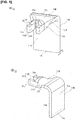
- Figure 1 is a view illustrating the terminal member 11 according to the first embodiment.
- Figure 1(A) is a perspective view illustrating the terminal member 11 from one side.
- Figure 1(B) is a perspective view illustrating the terminal member 11 from the other side.
- the terminal member 11 is a terminal joined to a winding 50 for electrical conduction therewith.
- the terminal member 11 configures, for example, a bus ring ( Figure 5 ) according to the second embodiment, together with a conductive band member.
- the terminal member 11 comprises a conductive portion 11M that joins the winding 50 ( Figure 15 ) and a supporting portion 11N that supports the conductive portion 11M.
- the terminal member 11 comprises a plate shape extending from one end 11a toward the other end 11b and is provided with a front surface 11c and a rear surface 11d.
- the terminal member 11 is formed by being bent into an L shape such that the side with the rear surface 11d faces inward, such that the supporting portion 11N and the conductive portion 11M bound the bent portion.
- the terminal member 11 is made from a conductive metal, such as copper.
- the conductive portion 11M comprises a pair of conductive surfaces (first conductive surface 11d1 and second conductive surface 11d2) that are branched in two from the side with the supporting portion 11N toward the one end 11a, and sandwich the winding 50.
- the first conductive surface 11d1 and the second conductive surface 11d2 respectively project from the front surface 11c of the conductive portion 11M toward the side with the rear surface 11d, and face each other.
- the portion that includes the first conductive surface 11d1 and that faces the side with the other end 11b, and the portion that includes the second conductive surface 11d2 and that faces the side with the other end 11b are respectively extended so as to be inclined from the supporting portion 11N toward the side with the conductive portion 11M.
- This inclined portion is configured from a portion bent in a crest fold shape (first deformed portion 11 p) and a portion bent in a trough fold shape (second deformed portion 11q).
- the thickness of the portion including the first conductive surface 11d1 along the one end 11a (h1) and the thickness of the portion including the second conductive surface 11d2 along the one end 11a (h1 and h2) are both the same as the thickness (h3) between the front surface 11c and the rear surface 11d in the supporting portion 11N.
- the supporting portion 11N extends from the conductive portion 11M toward the side with the other end 11b and supports the conductive portion 11M.
- the supporting portion 11N is also the portion that is joined to the conductive band member in, for example, the bus ring ( Figure 5 ) according to the second embodiment.
- the supporting portion 11N has a longer lateral width along the direction in which the pair of conductive surfaces, i.e., the first conductive surface 11d1 and the second conductive surface 11d2, face each other, than the lateral width of the conductive portion 11M.
- the terminal member 11 according to the first embodiment described above provides actions and effects by means of the following configurations.
- the terminal member 11 is joined to the winding 50 for electrical conduction therewith.
- the terminal member 11 comprises a conductive portion 11M and a supporting portion 11N.
- the conductive portion 11M comprises a pair of conductive surfaces (first conductive surface 11d1 and second conductive surface 11d2) having a plate shape extending from one end 11a toward the other end 11b and provided with a front surface 11c and a rear surface 11d, respectively projecting from the side with the front surface 11c to the side with the rear surface 11d, and opposite each other along a direction that intersects direction from the one end 11a toward the other end 11b.
- the supporting portion 11N extends from the conductive portion 11M toward the side with the other end 11b and supports the conductive portion 11M.
- the supporting portion 11N has a longer width along the direction in which the pair of conductive surfaces, the first conductive surface 11d1 and the second conductive surface 11d2, face each other, than that of the conductive portion 11M.
- the width of the supporting portion 11N is thicker than the width of the conductive portion 11M. Therefore, since the terminal member 11 is able to sufficiently support the conductive portion 11M that joins the winding 50 by means of the supporting portion 11N having a thicker width than the conductive portion 11M, it is possible to increase the rigidity of the entire terminal.
- the terminal member 11 is formed such that the portion that includes the first conductive surface 11d1 and that the side with faces the other end 11b, and the portion that includes the second conductive surface 11d2 and that the side with faces the other end 11b are respectively extended so as to be inclined from the supporting portion 11N toward the side with the conductive portion 11M, with respect to the rear surface 11d.
- the space between the supporting portion 11N and the conductive portion 11M is connected by an inclined portion, and it is possible to absorb, while transmitting to the supporting portion 11N, stress that is applied, for example, from the conductive portion 11M that joins the winding 50 to the supporting portion 11N, by the inclined portion. Therefore, the terminal member 11 can increase the rigidity of the entire terminal, from the conductive portion 11M to the supporting portion 11N.
- the terminal member 11 is formed such that the space between the supporting portion 11N and the conductive portion 11M is connected by a portion bent in a crest fold shape (first deformed portion 11p) and a portion bent in a trough fold shape (second deformed portion 11q).
- a terminal member 11 configured in this manner, it is possible to accurately form a terminal including a pair of conductive surfaces, the first conductive surface 10d1 and the second conductive surface 10d2, and to increase the rigidity of the entire terminal, by the crest fold shape and the trough fold shape between the supporting portion 11N and the conductive portion 11M.
- the terminal member 11 is formed such that the thickness of the portion of the conductive portion 11M that includes the first conductive surface 11d1 along the one end 11a (h1) and the thickness of the portion that includes the second conductive surface 11d2 along the one end 11a (h2) to be respectively equal to or greater than the thickness (h3) between the front surface 11c and the rear surface 11d in the supporting portion 11N.
- a terminal member 11 configured in this manner, it is possible to make the rigidity of the portion on the distal end side including the first conductive surface 11d1 (conductive portion 11M including the first conductive surface 11d1) and of the portion on the distal end side including the second conductive surface 11d2 (conductive portion 11M including the second conductive surface 11d2) to be respectively equal to or greater than the rigidity of the proximal end side portion (supporting portion 11N).
- the terminal member 11 is formed in an L shape from the supporting portion 11N to the conductive portion 11M, such that the side with the rear surface 11d faces inward.
- the terminal member 11 configured in this manner, it is possible to form the entire terminal to be smaller compared with when the terminal is formed extending linearly from the supporting portion 11N to the conductive portion 11M. Furthermore, the terminal member 11 comprises a pair of conductive surfaces, the first conductive surface 11d1 and the second conductive surface 11d2, on the inward side (inner side) of the L shaped bend. Therefore, in the terminal member 11, it is possible to avoid interference between the pair of conductive surfaces, the first conductive surface 11d1 and the second conductive surface 11d2, and a structure disposed on the outward side (outer side) of the terminal member 11.
- Figure 2 is a view illustrating the method for manufacturing a terminal member 11 using the manufacturing device 100 according to the first embodiment, showing the state in which the workpiece 10 is attached to the manufacturing device 100.
- Figure 2(A) is a perspective view showing said state.
- Figure 2(B) is a top view showing said state.
- Figure 3 shows a state in which the workpiece 10 is press-worked by the manufacturing device 100.
- Figure 3(A) is a perspective view showing said state.
- Figure 3(B) is a top view showing said state.
- the method for manufacturing the terminal member 11 is for the manufacture of a terminal member 11 for electrical conduction with a winding 50, by working a workpiece (workpiece 10).
- the workpiece 10 has a plate shape extending from one end 10a toward the other end 10b, and has a front surface 10c and a rear surface 10d, and which is provided, at the one end 10a, with a recessed portion 10e that is cut out and recessed from the front surface 10c to the rear surface 10d.
- the manufacturing device 100 embodies the method for manufacturing the terminal member 11 described above.
- the manufacturing device 100 comprises a supporting member 101 that supports the workpiece 10 at the recessed portion 10e, a lower supporting member 102 and an upper supporting member 103 that sandwich and fix a fixing region 10f of the workpiece 10 from above and below, a right pressing member 104 and a left pressing member 105 that press a pair of pressed regions 10g of the workpiece 10, and a controller 106 for controlling the working of the workpiece 10, as illustrated in Figure 2 .
- the supporting member 101 supports the workpiece 10 at the recessed portion 10e.
- the supporting member 101 corresponds to a so-called nest.
- the supporting member 101 has a plate shape, and is disposed along the vertical direction so as to stand upright.
- One side surface (right side in Figure 2(B) ) of the supporting member 101 in the short side direction is curved in a semicircular shape to match the shape of the recessed portion 10e of the workpiece 10 to be abutted there against.
- the recessed portion 10e of the workpiece 10 is inserted and fitted to the portion of the supporting member 101 that is curved in a semicircular shape.
- the lower supporting member 102 and the upper supporting member 103 sandwich and fix a fixing region 10f of the workpiece 10 (region spaced from the recessed portion 10e of the workpiece 10 toward the side with the other end 10b) from above and below.
- the lower supporting member 102 has a plate shape, and is disposed along the horizontal direction.
- the lower supporting member 102 is primarily formed by cutting out both sides of the end portion on one side along the longitudinal direction (left side in Figure 2(B) ) to match the shape of the fixing region 10f of the workpiece 10.
- the upper supporting member 103 is shaped in the same manner as the lower supporting member 102.
- the upper supporting member 103 and the lower supporting member 102 are respectively spaced from the opposing supporting member 101 in the horizontal direction (left side in Figure 2(B) ) by a length corresponding to the portion of the unpressed region 10h of the workpiece 10 (region of the portion of the workpiece 10 to be bent facing the side with the other end 10b), as illustrated in Figure 2(B) .
- the right pressing member 104 and the left pressing member 105 press the pair of pressed regions 10g of the workpiece 10 (regions further toward the two sides along the one end 10a than the recessed portion 10e).
- the right pressing member 104 and the left pressing member 105 correspond to so-called punches.
- the right pressing member 104 has a rectangular parallelepiped shape and presses the pressed region 10g on the lower side of the workpiece 10 shown in Figure 2(B) of the pair of pressed regions 10g.
- the right pressing member 104 maintains a state of being spaced from the supporting member 101 with respect to the horizontal direction along the one end 10a (lower side in Figure 2(B) ) by the thickness of the workpiece 10 (h3).
- the right pressing member 104 is moved in the vertical direction by a single-axis linear moving stage.
- the left pressing member 105 has the same shape as the right pressing member 104.
- the left pressing member 105 presses the pressed region 10g on the upper side of the workpiece 10 shown in Figure 2(B) of the pair of pressed regions 10g.
- the left pressing member 105 maintains a state of being spaced from the supporting member 101 with respect to the horizontal direction along the one end 10a (upper side in Figure 2(B) ) by the thickness of the workpiece 10 (h3).
- the left pressing member 105 is moved in the vertical direction together with the right pressing member 104 by the single-axis linear moving stage.
- the right pressing member 104 and the left pressing member 105 may be configured as one member. Specifically, for example, the top and bottom of a pressing member formed in a U shape may be disposed upside down, and the distal end, which is branched in two, may be configured as a pair of pressing portions (right pressing portion and left pressing portion).
- the controller 106 controls the working of the workpiece 10.
- the controller 106 controls the operation of the linear moving stage on which the right pressing member 104 and the left pressing member 105 are mounted.
- the controller 106 comprises a ROM, a CPU, and a RAM.
- a control program related to the working of the workpiece 10 is stored in the ROM (Read Only Memory).
- the control program contains information related to the movement distance, the movement speed and the like of the right pressing member 104 and the left pressing member 105.
- the CPU Central Processing Unit
- the controller 106 controls the driving of the linear moving stage.
- Various data related to the linear moving stage under control are temporarily stored in the RAM (Random Access Memory). The data are, for example, related to the movement distance of the linear moving stage.
- Figure 2 illustrates the state in which the workpiece 10 is attached to the manufacturing device 100 before the workpiece 10 is worked.
- the supporting member 101 supports the recessed portion 10e of the workpiece 10 in contact therewith.
- the lower supporting member 102 and the upper supporting member 103 sandwich and fix the fixing region 10f spaced from the recessed portion 10e of the workpiece 10 toward the side with the other end 10b.
- the right pressing member 104 and the left pressing member 105 are on standby above the pair of pressed regions 10g further toward the two sides along the one end 10a than the recessed portion 10e.
- Figure 3 illustrates the state in which the workpiece 10 is press-worked using the manufacturing device 100 after the workpiece 10 is worked.
- the right pressing member 104 and the left pressing member 105 cause the pair of pressed regions 10g of the workpiece 10 to be placed along the supporting member 101 and press and bend the pair of pressed regions from the front surface 10c toward the side with the rear surface 10d only once.
- the rear surface 10d portions facing each other with the supporting member 101 interposed therebetween become a pair of conductive surfaces that face each other (first conductive surface 10d1 and second conductive surface 10d2).
- the right pressing member 104 and the left pressing member 105 press portions of the workpiece 10 to be bent, excluding the portion that faces the side with the other end 10b (unpressed region 10h).
- the unpressed region 10h deforms accompanying the bending of the adjacent pair of pressed regions 10g. Therefore, since the side with the one end 10a spaced from the fixing region 10f is more greatly bent than the side with the other end 10b adjacent to the fixing region 10f, which is fixed and is not easily deformed, the unpressed region 10h of the workpiece 10 is bent to be inclined from the side with the other end 10b toward the side with the one end 10a.
- the right pressing member 104 and the left pressing member 105 bend the workpiece 10, with each of the one end portion of the unpressed region 10h adjacent to the fixing region 10f (first deformed portion 10p), and the other end portion of the unpressed region 10h adjacent to the pair of pressed regions 10g (second deformed portion 10q) as a boundary. Since the first deformed portion 10p is pushed down along the edge of the fixing region 10f, which is fixed and is not easily deformed, the first deformed portion is bent in a crest fold shape. Since the second deformed portion 10q is pressed against the supporting member 101, the second deformed portion is bent in a trough fold shape along the edges of the pair of pressed regions 10g, which are easily deformed. Therefore, the unpressed region 10h of the workpiece 10 is bent such that a crest fold shape and a trough fold shape are continuous from the other end 10b toward the side with the one end 10a.
- the method for manufacturing a terminal member 11 according to the first embodiment described above provides actions and effects by means of the following configurations.
- the method for manufacturing a terminal member 11 is used for manufacturing a terminal member 11 for electrical conduction with a conductive member (a winding 50) by working a workpiece (workpiece 10) which comprises a plate shape extending from one end 10a toward the other end 10b and provided with a first surface (a front surface 10c) and a second surface (a rear surface 10d), and which is provided, at the one end 10a, with a recessed portion 10e that is cut out and recessed from the front surface 10c to the rear surface 10d.
- a workpiece which comprises a plate shape extending from one end 10a toward the other end 10b and provided with a first surface (a front surface 10c) and a second surface (a rear surface 10d), and which is provided, at the one end 10a, with a recessed portion 10e that is cut out and recessed from the front surface 10c to the rear surface 10d.
- the recessed portion 10e is supported by being abutted against a supporting member 101, a portion (a fixing region 10f) spaced from the recessed portion 10e toward the side with the other end 10b is fixed, and both side portions (a pair of pressed regions 10g) along the one end 10a from the recessed portion 10e are bent while being pressed from the front surface 10c toward the side with the rear surface 10d, thereby forming, a pair of conductive surfaces (the first conductive surface 10d1 and the second conductive surface 10d2) for conduction with the winding 50, the rear surface 10d of the portions facing each other with the supporting member 101 interposed therebetween.
- a pair of conductive surfaces, a first conductive surface 10d1 and a second conductive surface 10d2 are formed by pressing a pair of pressed regions 10g of the workpiece 10 along the supporting member 101. That is, by using this method for manufacturing a terminal member 11, it is possible to form a pair of conductive surfaces, the first conductive surface 10d1 and the second conductive surface 10d2, which face each other, by means of a single pressing based on the supporting member 101. Therefore, this method for manufacturing a terminal member 11 is capable of greatly improving the productivity of the terminal member 11 to be joined to a winding 50 for electrical conduction therewith.
- this method for manufacturing a terminal member 11 is capable of providing great rigidity to the terminal member 11 to be manufactured.
- the terminal member 11 to be manufactured is highly rigid, so that even when said terminal member interferes with other component members, misalignment does not readily occur; therefore, it is possible to maintain positional accuracy, and handling becomes easy.
- the workpiece 10 to be used for working comprises a plate shape having only the recessed portion 10e on the one end 10a, and breaking and cutting are not performed when working the workpiece 10. That is, the yield of the workpiece 10 itself to be used for working is high, and material is not discarded during working of the workpiece 10. Therefore, the method for manufacturing a terminal member 11 is capable of reducing the material costs required for the workpiece 10.
- the pressing of the portions of the workpiece 10 to be bent excludes the portion (the unpressed region 10h) facing the side with the other end 11b.
- the pair of pressed regions 10g are pressed toward the side with the rear surface 10d across the unpressed region 10h.
- the unpressed region 10h is relatively largely bent so as to be inclined from the side with faces the other end 11b toward the one end 10a side.
- this method for manufacturing a terminal member 11 is capable of imparting great rigidity to the entire terminal member 11 to be manufactured by the inclined portion (the unpressed region 10h) that is formed between the proximal end side (the side with the fixing region 10f) and the distal end side (the side with the pair of the pressed regions 10g).
- the method for manufacturing a terminal member 11 configured in this manner, it is possible to bend the workpiece 10, with each of the one end portion of the unpressed region 10h adjacent to the fixing region 10f (first deformed portion 10p), and the other end portion of the unpressed region 10h adjacent to the pair of pressed regions 10g (second deformed portion 10q) as a boundary, by a single pressing.
- first deformed portion 10p in a crest fold shape along the edge of the fixing region 10f
- the second deformed portion 10q in a trough fold shape along the edges of the pair of pressed regions 10g abutting the supporting member 101, as seen from the front surface 10c toward the rear surface 10d side of the workpiece 10.
- this method for manufacturing a terminal member 11 is capable of accurately forming the terminal member 11, which includes a pair of conductive surfaces, a first conductive surface 10d1 and a second conductive surface 10d2, while providing great overall rigidity to the terminal member 11 to be manufactured, by bending the unpressed region 10h of the workpiece 10 such that the crest fold shape and the trough fold shape are continuous from the other end 10b toward the one end 10a side.
- a method for manufacturing a terminal member 11 since it is possible to suppress the occurrence of spring back by connecting a crest fold shape and a trough fold shape, it becomes possible to prevent the shape of the terminal member 11 from deforming after manufacture.
- this method for manufacturing a terminal member 11 is capable of providing to each of the distal end side portion, including the first conductive surface 11d1 and the distal end side portion including the second conductive surface 11d2 the same or greater rigidity than that of the proximal end side portion.
- Figure 4 is a perspective view illustrating a terminal member 12 according to a modified example of the first embodiment.
- the terminal member 12 is formed bent into an L shape from a supporting portion 12N to a conductive portion 12M, such that the front surface 12c side faces inward.
- a workpiece 10 is worked by a manufacturing device 100 to form a pair of conductive surfaces, a first conductive surface 12d1 and a second conductive surface 12d2.
- the terminal member 12 is formed by being bent into an L shape in the direction opposite to that of the terminal member 11, such that the front surface 12c side faces inward, bounded by the supporting portion 12N and the conductive portion 12M.
- the terminal member 12 according to the modified example of the first embodiment provides actions and effects by means of the following configurations, in addition to the actions and effects of the terminal member 11 according to the first embodiment.
- the terminal member 12 is formed bent into an L shape from the supporting portion 12N to the conductive portion 12M, such that the front surface 12c side faces inward.
- the terminal member 12 configured in this manner comprises a pair of conductive surfaces, the first conductive surface 12d1 and the second conductive surface 12d2, on the outward side (outer side) of the L shaped bend. Therefore, with the terminal member 12, it is possible to avoid interference between the pair of conductive surfaces, the first conductive surface 12d1 and the second conductive surface 12d2, and a structure positioned on the inward side (inner side) of the terminal member 12 (for example, a main frame 212 of the manufacturing device 200 of the bus ring assembly 40 according to the third embodiment, described below).
- the bus ring 20 is a wiring member that causes electric power supplied from the outside to flow through a plurality of windings 50.
- bus ring 20 The configuration of the bus ring 20 will be described with reference to Figure 5 and Figure 6 .
- Figure 5 is a perspective view illustrating a bus ring 20 according to the second embodiment.
- Figure 6 is an exploded perspective view illustrating the main parts of the bus ring 20 of Figure 5 .
- the bus ring 20 comprises terminal members 21 and a conductive band member 22.
- the terminal members 21 have the same configuration as the terminal member 11.
- the terminal members 21 are illustrated by simplifying the outer shape of the terminal member 11.
- the conductive band member 22 conducts electric power supplied from the outside to each of the terminal members 21.
- the conductive band member 22 is made from a conductive metal, such as copper.
- the conductive band member 22 has an elongated shape and is curved into an arc shape. Both ends of the conductive band member 22 in the longitudinal direction are spaced.
- the conductive band member 22 joins a plurality of terminal members 21 to the inner perimeter surface along the longitudinal direction thereof at a predetermined interval.
- Each of the terminal members 21 is provided such that the distal end side of the conductive portion 21M thereof faces the radially inward direction of the conductive band member 22.
- the conductive band member 22 and the terminal members 21 are joined to each other by the application of ultrasonic waves to the abutting portions to generate vibrations and thus frictional heat, locally melting the abutting portions.
- the bus ring 20 according to the second embodiment described above provides actions and effects by means of the following configurations.
- the bus ring 20 comprises terminal members 21 and a conductive band member 22.
- Each terminal member 21 is provided with a conductive portion 21M comprising a pair of conductive surfaces, a first conductive surface 21d1 and a second conductive surface 21d2, having a plate shape extending from one end 21a toward the other end 21b and provided with a front surface 21c and a rear surface 21d, respectively projecting from the front surface 21c to the rear surface 21d side, and opposite each other along a direction that intersects the direction from the one end 21a toward the other end 21b, and with a supporting portion 21N extending from the conductive portion 21M toward the other end 21b side and supporting the conductive portion 21M, and the width of the supporting portion 21N along the direction in which the pair of conductive surfaces, the first conductive surface 21d1 and the second conductive surface 21d2, face each other is wider than that of the conductive portion 21M.
- the conductive band member 22 comprises an elongated shape, which joins a plurality of terminal members 21
- the width of the supporting portion 21N is greater than the width of the conductive portion 21M. That is, since the terminal members 21 provided to the bus ring 20 are able to sufficiently support the conductive portion 21M that joins the winding 50 by means of the supporting portion 21N having a greater width than the conductive portion 21M, it is possible to increase the rigidity of the entire terminal. Therefore, even if stress is applied to the terminal members 21 or the conductive band member 22 at the time that the winding 50 is joined to the terminal members 21, or after the winding 50 is joined to the terminal members 21, the bus ring 20 is able to prevent the breakage thereof.
- the radial thickness of the bus ring 30 is formed to be less than that of the bus ring 20 described in the second embodiment.
- bus ring 30 The configuration of the bus ring 30 will be described with reference to Figure 7 and Figure 8 .
- Figure 7 is a perspective view illustrating a bus ring 30 according to a modified example of the second embodiment.
- Figure 8 is an exploded perspective view illustrating the main parts of the bus ring 30 of Figure 7 .
- the bus ring 30 comprises terminal members 31 and a conductive band member 32.
- Each terminal member 31 has the same specifications as the terminal member 21 except for the shape of the supporting portion 31N.
- the supporting portion 31N is formed such that the length thereof along the longitudinal direction (vertical direction illustrated in Figure 7 ) is half the length along the longitudinal direction of the supporting portion 21N of the terminal member 21.
- a joint portion 31t is formed by partially reducing the thickness of the front surface 31c side (radially outward side shown in Figure 7 ) of the portion that is joined to the conductive band member 32. Since the joint portion 31t is formed by reducing the thickness of only the lower portion along the longitudinal direction of the supporting portion 31N (vertical direction shown in Figure 7 ) and the thickness of the upper portion is not changed, the terminal member 31 maintains overall strength.
- the joint portion 32t is formed by reducing the thickness of the portion that is joined to the terminal member 31. Since the joint portion 32t is formed by reducing the thickness of only the upper portion along the short side direction (vertical direction shown in Figure 7 ) and the thickness of the lower portion is not changed, the conductive band member 32 maintains overall strength.
- bus ring 30 according to the modified example of the second embodiment described above provides actions and effects by means of the following configurations.
- the thickness of the joint portion 31t of the terminal member 31 that is joined to the conductive band member 32 is formed to be less than the thickness of the portion surrounding the joint portion 31t and/or the thickness of the joint portion 32t of the conductive band member 32 that is joined to the terminal member 31 is formed to be less than the thickness of the portion surrounding the joint portion 32t.
- bus ring 30 configured in this manner, when a plurality (for example, four: N phase, U phase, V phase, and W phase) of bus rings are stacked, it is possible to reduce the gaps between adjacent bus rings 30, compared with the gaps between adjacent bus rings 20. Therefore, the bus ring 30 is capable of improving the stacking efficiency when a plurality thereof is laminated.
- the bus ring 30 is formed such that the sum of the thickness of the joint portion 31t of the terminal member 31 and the thickness of the joint portion 32t of the conductive band member 32 is equal to or less than the thickness of the portion around the joint portion 31t of the terminal member 31, and/or equal to or less than the thickness of the portion around the joint portion 32t of the conductive band member 32.
- bus ring 30 configured in this manner, when a plurality (for example, four: N phase, U phase, V phase, and W phase) of bus rings are stacked, it is possible to eliminate the gaps between adjacent bus rings 30. Therefore, the bus ring 30 is capable of maximizing the stacking efficiency when a plurality thereof is laminated.
- the bus ring assembly 40 is a power distribution assembly that causes electric power supplied from the outside to flow through a plurality of windings 50 of the U phase, V phase, and N phase.
- the manufacturing device 200 can be used to easily manufacture the bus ring assembly 40.
- Figure 9 is a perspective view illustrating a bus ring assembly 40 according to the third embodiment.
- Figure 10 is a top view illustrating the main parts of the bus ring assembly 40 of Figure 9 .
- Figure 11 is a view illustrating the main part of the bus ring assembly 40 of Figure 9 , which is a portion thereof, in a state in which an insulating band member 44P and an insulating band member 44Q are bonded to both sides in the radial direction of a U-phase conductive band member 42U.
- Figure 11(A) is a perspective view showing said main part.
- Figure 11(B) is a side view showing said main part.
- the bus ring assembly 40 comprises bus rings having terminal members 41 and conductive band members 42, high-voltage members 43 for supplying electric power from a three-phase AC power source to the conductive band members 42, and insulating band members 44 for insulating between adjacent bus rings.
- the bus rings have terminal members 41 and conductive band members 42.
- the terminal members 41 have the same specifications as the terminal members 21.
- the conductive band members 42 have the same specifications as the conductive band member 22.
- the bus rings are configured from four phases: U phase, V phase, W phase, and N phase.
- the U-phase, V-phase, and W-phase bus rings supply electric power supplied from a three-phase AC power source to the winding 50, via the high-voltage members 43, the conductive band members 42, and the terminal members 41.
- Each terminal member 41 is connected to one end of the winding 50 ( Figure 15 ).
- the winding 50 is configured by being wound in a coil shape (not shown) with respect to an insulator that covers the slot portion of the stator of a stator assembly.
- the U-phase bus ring has terminal members 41U and conductive band members 42U.
- the V-phase bus ring has terminal members 41V and conductive band members 42V.
- the W-phase bus ring has terminal members 41W and conductive band members 42W.
- the N-phase bus ring corresponds to ground for the U-phase, V-phase, and W-phase bus rings.
- the N-phase bus ring has terminal members 41N and conductive band members 42N.
- the N-phase bus ring connects the terminal member 41N to the other end of the winding 50.
- the bus rings are wound radially outwardly in the order of N phase, U phase, V phase, and W phase, as illustrated in Figure 10 . Therefore, the terminal members 41 are configured such that the length along the radial direction of the conductive portion becomes longer in the order of terminal members 41N, 41U, 41V, and 41W. With such a configuration, the positions of the pairs of conductive surfaces of the respective terminal members 41 are arranged concentrically.
- the high-voltage members 43 supply electric power from a three-phase AC power source to the conductive band members 42.
- the high-voltage members 43 are formed in an elongated shape, and the proximal end sides thereof are joined to the upper ends of the conductive band members 42 shown in Figure 9 .
- the high-voltage members 43 are extended so as to project radially outwardly from the conductive band members 42.
- a plurality of locations of the high-voltage members 43 from the proximal end side to the distal end side are bent downward in Figure 9 .
- Wires of the three-phase AC power source are connected via through-holes formed on the distal end sides of the high-voltage members 43.
- the U-phase, V-phase, and W-phase high-voltage members 43U, 43V, and 43W are ultrasonically joined to the conductive band members 42U, 42V, and 42W, respectively, as illustrated in Figure 9 .
- the insulating band members 44 provide insulation between adjacent bus rings.
- the insulating band members 44 are made from an insulating material, for example, and are formed in an elongated shape.
- the insulating band members 44 are not made from molding resin or the like, and thus can be configured with a thickness of several tens of ⁇ m.
- the short side direction width of the insulating band members 44 is longer than that of the insulating band member 42.
- the insulating band member 44 has a thickness h5 that is extended downward by a thickness h6 and extended upward by a thickness h7, as illustrated in Figure 11(B) .
- An insulating band member 44P is laminated between the conductive band members 42N and 42U, as illustrated in Figure 10 .
- an insulating band member 44Q is laminated between the conductive band members 42U and 42V
- an insulating band member 44R is laminated between the conductive band members 42V and 42W
- an insulating band member 44S is laminated radially outwardly with respect to the conductive band member 42W.
- the insulating band members 44P, 44Q, and 44R are provided with adhesive members on the radially inner sides and outer sides.
- the adhesive member is, for example, a silicone-based adhesive and is applied on both surfaces of the insulating band members 44. That is, the insulating band members 44P, 44Q, and 44R are configured like a double-sided adhesive tape having insulating properties.
- the insulating band member 44S is provided with an adhesive member on the radially inner side.
- the adhesive member is, for example, a silicone-based adhesive and is applied on one surface of the insulating band member 44S. That is, the insulating band member 44S is configured like a single-sided adhesive tape having insulating properties.
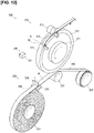
- Figure 12 is a perspective view illustrating a manufacturing device 200 of the bus ring assembly 40 according to the third embodiment.
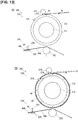
- Figure 13 is a view illustrating a state in which a conductive band member 42 is wound around the main frame 212 by the manufacturing device 200 of Figure 12 .
- Figure 13(A) is a side view illustrating the state before winding.
- Figure 13(B) is a side view showing the state after winding.
- Figure 14 is a view illustrating a state in which an insulating band member 44 is wound around and bonded to the conductive band member 42.
- Figure 14(A) is a side view illustrating the state before winding.
- Figure 14(B) is a side view showing the state after winding.
- the method for manufacturing the bus ring assembly 40 is a method in which conductive band members 42 and insulating band members 44 are alternately wound and laminated along the longitudinal direction.
- the manufacturing device 200 is a device that embodies the method for manufacturing the bus ring assembly 40 described above.
- the manufacturing device 200 comprises a first winding unit 210 that winds the conductive band member 42 joined with the terminal members 41 into an arc shape, a second winding unit 220 that winds the insulating band member 44 into an arc shape, and a control unit 230 that controls the operations of the first winding unit 210 and the second winding unit 220, as illustrated in Figure 12 .
- the first winding unit 210 winds the conductive band member 42 joined with the terminal members 41 into an arc shape.
- the first winding unit 210 comprises a rotating roller 211 used for winding the conductive band member 42, a main frame 212, onto which the conductive band member 42 is wound, a pressing roller 213 that presses the conductive band member 42 against the main frame 212, a position sensor 214 that detects the positions of the terminal members 41 that are joined to the conductive band member 42 and the position of the distal end of the conductive band member 42, and a rotation sensor 215 that detects the winding length of the conductive band member 42.
- the rotating roller 211 is formed in a cylindrical shape.
- the rotating roller 211 is provided with a rotating mechanism and rotates the main frame 212 attached to the outer perimeter surface.
- the main frame 212 is formed in a cylindrical shape.
- the outer diameter of the main frame 212 is set to be the same as the designed inner diameter of the N-phase conductive band member 42N after being wound.
- the main frame 212 is configured to be detachable from the rotating roller 211.
- the main frame 212 causes the conductive band material 42 to be wound around the outer perimeter surface thereof.
- the pressing roller 213 is formed in a cylindrical shape.
- the pressing roller 213 is disposed in proximity to the main frame 212 and is configured to be freely rotatable.
- the pressing roller 213 is rotated following the main frame 212 in a state of pressing the conductive band member 42 that is wound around the main frame 212.
- the position sensor 214 detects the positions of the terminal members 41 that are joined to the conductive band member 42 and the position of the distal end of the conductive band member 42 that is wound onto the main frame 212.
- the position sensor 214 is disposed in a portion where the main frame 212 and the pressing roller 213 face each other, so as to face the outer perimeter edge of the side surface of the main frame 212.
- the position sensor 214 detects the positions of the terminal members 41 that are joined to the conductive band member 42 and the position of the distal end of the conductive band member 42 by, for example, irradiating laser light onto the winding path of the conductive band member 42 and receiving the light reflected from the distal end of the conductive band member 42.
- the position sensor 214 may also detect the positions of the terminal members 41 that are joined to the conductive band member 42 and the position of the distal end of the conductive band member 42 by image recognition using a camera. The position sensor 214 transmits the detected data to the control unit 230. The transmitted detected data are used for controlling the rotating roller 211.
- the rotation sensor 215 detects the winding length of the conductive band member 42 that is wound around the main frame 212.
- the rotation sensor 215 is disposed on the downstream side of the position sensor 214 in the transport direction of the conductive band member 42, so as to face the outer perimeter edge of the side surface of the main frame 212.
- the rotation sensor 215 measures the rotation angle of the main frame 212 and detects the winding length of the conductive band member 42 along the radial direction from the outer diameter and the rotation angle of the main frame 212.
- the rotation sensor 215 transmits the detected data to the control unit 230.
- the transmitted detected data are used for controlling the rotating roller 211.
- the second winding unit 220 winds the insulating band member 44 in an arc shape.
- the second winding unit 220 comprises a supply roller 221 that supplies an insulating sheet 44A, a biasing roller 222 that biases the insulating band member 44 to the conductive band member 42 that is wound around the main frame 212, a winding roller 223 that winds a separator 44k while the insulating sheet 44A is pulled from the supply roller 221, a cutting blade 224 that cuts only the insulating band member 44 while leaving the separator 44k of the insulating sheet 44A, and a support table 225 that supports the separator 44k of the insulating sheet 44A that is pressed by the cutting blade 224.
- the supply roller 221 is formed in a cylindrical shape, and an insulating sheet 44A is wound thereon.
- the insulating sheet 44A is configured by providing an insulating band member 44 on one side of a film-like separator 44k made of, for example, polyethylene terephthalate.
- the supply roller 221 winds the insulating sheet 44A such that the insulating band member 44 is on the radially outward side and the separator 44k is on the radially inward side.
- the supply roller 221 is rotated following the winding roller 223 and supplies the insulating sheet 44A toward the main frame 212.
- the biasing roller 222 is formed in a cylindrical shape.
- the biasing roller 222 is disposed in proximity to the main frame 212 and is configured to be freely rotatable.
- the biasing roller 222 biases, while applying tension to, the insulating band member 44 abutting the conductive band member 42, and is rotated following the main frame 212 and the winding roller 223.
- the winding roller 223 is formed in a cylindrical shape.
- the winding roller 223 is provided with a rotating mechanism and winds and collects only the separator 44k while the insulating sheet 44A is pulled from the supply roller 221.
- the cutting blade 224 is provided with a sharp linear blade at the distal end thereof.
- the cutting blade 224 is disposed between the supply roller 221 and the biasing roller 222.
- the cutting blade 224 is positioned to face the separator 44k side, along the short side direction of the insulating sheet 44A.
- the cutting blade 224 cuts only the separator 44k linearly.
- the support table 225 is formed in a plate shape.
- the support table 225 is disposed opposing the cutting blade 224 across the insulating sheet 44A.
- the cutting blade 224 supports the separator 44k of the insulating sheet 44A that is pressed by the cutting blade 224.
- the control unit 230 controls the operations of the first winding unit 210 and the second winding unit 220.
- the control unit 230 comprises a controller 231 that controls the operations of the rotating roller 211, the position sensor 214, the rotation sensor 215, the winding roller 223, and the cutting blade 224.
- the controller 231 comprises a ROM, a CPU, and a RAM.
- a control program related to the winding of the conductive band member 42 and the insulating band member 44 is stored in the ROM (Read Only Memory).
- the control program contains information related to the operations of the rotating roller 211, the position sensor 214, the rotation sensor 215, the winding roller 223, and the cutting blade 224.
- the CPU (Central Processing Unit) of the controller 231 controls the operations of each of the component members described above.
- Various data related to each component member under control are temporarily stored in the RAM (Random Access Memory).
- the first winding unit 210 winds the conductive band member 42 joined to the terminal members 41 into an arc shape, under the control of the control unit 230, as illustrated in Figure 13.
- Figure 13(A) shows the state before the conductive band member 42 is wound around the main frame 212.
- Figure 13(B) shows the state after the conductive band member 42 is wound around the main frame 212.
- the rotating roller 211 rotates the main frame 212 attached to the outer perimeter surface.
- the main frame 212 presses, while bending, the supplied conductive band member 42 against the pressing roller 213, and winds the conductive band member around the outer perimeter surface thereof.
- the second winding unit 220 winds the insulating band member 44 into an arc shape while bonding the insulating band member to the conductive band member 42, under the control of the control unit 230, as illustrated in Figure 14.
- Figure 14(A) shows the state before winding the insulating band member 44 around the conductive band member 42.
- Figure 14(B) shows the state after winding the insulating band member 44 around the conductive band member 42.
- the supply roller 221 is rotated following the winding roller 223 and supplies the insulating sheet 44A in a direction toward the conductive band member 42 that is wound around the main frame 212.
- the cutting blade 224 cuts only the insulating band member 44 along the short side direction of the insulating sheet 44A, at a predetermined interval with respect to the longitudinal direction.
- the biasing roller 222 is rotated following the winding roller 223 while biasing the insulating band member 44 against the conductive band member 42, such that the conductive band member 42 and the insulating band member 44 are brought in close contact and bonded.
- the winding roller 223 winds and collects the separator 44k.
- the manufacturing device 200 is configured such that, before each component member of the bus ring assembly 40 is wound and laminated, a double-sided tape is affixed to the outer perimeter surface of the main frame 212, so that the main frame 212 and the conductive band member 42N can be temporarily fixed and so that the conductive band member 42N positioned on the radially innermost side is not detached from the main frame 212.
- the double-sided tape is peeled off of the main frame 212 and the conductive band member 42N after manufacturing the bus ring assembly 40.
- the manufacturing device 200 laminates, while alternately winding with respect to the main frame 212, conductive band members 42 and insulating band members 44 in the order of N phase, U phase, V phase, and W phase. Specifically, the manufacturing device 200 repeats the steps shown in Figure 13 and Figure 14 and winds and laminates the conductive band member 42N, the insulating band member 44P, the conductive band member 42U, the insulating band member 44Q, the conductive band member 42V, the insulating band member 44R, the conductive band member 42W, and the insulating band member 44S, in that order, to manufacture the bus ring assembly 40.
- the manufacturing device 200 adjusts the relative position of the conductive band member 42 to be wound around the main frame 212 during the manufacturing of the bus ring assembly 40 by a position sensor 214 or the like. That is, the rotating roller 211 winds, while rotating, each of the conductive band members 42 around the main frame 212, such that the terminal members 41N, 41U, 41V and 41W, which are respectively joined to the conductive band members 42N, 42U, 42V, and 42W, are evenly arranged in an arc shape along the radial direction, based on detected data obtained from the position sensor 214 and the like.
- the insulating band member 44P, the insulating band member 44Q, and the insulating band member 44R are respectively joined to radially adjacent conductive band members 42 by adhesive members applied to both surfaces thereof.
- the insulating band member 44S is joined to the conductive band member 42W by an adhesive member applied to one surface thereof, while preventing a short circuit with another member positioned in the radially outward direction.
- the manufactured bus ring assembly 40 is completed by bending a plurality of locations from the proximal end side to the distal end side of the high-voltage members 43U, 43V, and 43W, in a state of being detached from the manufacturing device 200 or in a state of being attached to the manufacturing device 200.
- the high-voltage members 43U, 43V, and 43W are joined to the conductive band members 42U, 42V, and 42W, as illustrated in Figure 9 .
- the method for manufacturing a bus ring assembly 40 according to the third embodiment described above provides actions and effects by means of the following configurations.
- conductive band members 42 having an elongated shape comprising a plurality of terminal members 41 that are joined with a winding 50 and that cause electric power supplied from the outside to flow through each of the terminal members 41, and insulating band members 44 having an elongated shape and provided with insulating properties are alternately wound and laminated along the longitudinal direction.
- the bus ring assembly 40 can be easily manufactured by an extremely simple method of alternately winding conductive band members 42 and insulating band member 44 along the longitudinal direction.
- low-cost insulating band members 44 for insulation are used for insulation between adjacent conductive band members 42 (for example, the conductive band member 42 for the N phase and the conductive band member 42 for the U phase) instead of a high-cost insulating resin case.
- high-cost automated facilities or skilled workers for embedding the component members into the resin case are not required. Therefore, it is possible to manufacture the bus ring assembly 40 at low cost.
- the insulating band members 44 taking the place of a resin case, can be configured with a thickness of several tens of ⁇ m. Therefore, the bus ring assembly 40 can be reduced in size.
- conductive band members 42 and insulating band members 44 are alternately wound and laminated with respect to a wound member (main frame 212).
- bus ring assembly 40 configured in this manner, since conductive band members 42 and insulating band members 44 are alternately wound so as to extend along the outer surface of the main frame 212, it is possible to form the bus ring assembly 40 with high precision. In addition, it is possible to form bus ring assemblies 40 of various shapes by simply changing the outer shape of the main frame 212. Furthermore, compared with the case in which an insulating resin case is used for insulation between adjacent conductive band members 42, a high-cost automated facility or the like for embedding component members in the resin case is not required, and the assembly of the bus ring assembly 40 can be carried out by a small-scale facility. In particular, when such a method for manufacturing a bus ring assembly 40 is implemented, there are few moving parts, as shown in the manufacturing device 200, and manufacturing can be carried out in a small space.
- insulating band members 44 provided with adhesive members are joined and laminated to conductive band members 42.
- the method for manufacturing a bus ring assembly 40 configured in this manner, since the conductive band members 42 and the insulating band members 44 are alternately wound and joined, it is possible to easily integrate the bus ring assembly 40.
- a thin adhesive member it is possible to improve the laminating efficiency of the conductive band members 42 and the insulating band members 44.
- the insulating band member 44 which has a short side direction width that is longer than the short side direction width of the conductive band member 42, is extended past both ends of the conductive band member 42 in the short side direction, while being laminated on the conductive band member 42.
- a motor using the bus ring assembly 40 and to prevent the occurrence of electric discharge between adjacent conductive band members 42 (for example, the N-phase conductive band member 42N and the U-phase conductive band member 42U), when the terminal members 41 electrically conduct from the high-voltage members 43 via the conductive band members 42. That is, an electric discharge does not occur unless, for example, in the space between the short side direction end of the N-phase conductive band member 42N and the short side direction end of the U-phase conductive band member 42U, the insulating band member 44 extending in the short side direction from those ends is bypassed.
- adjacent conductive band members 42 for example, the N-phase conductive band member 42N and the U-phase conductive band member 42U
- the method for manufacturing a bus ring assembly 40 configured in this manner it is possible to sufficiently suppress the occurrence of electric discharge in the bus ring assembly 40 after manufacture. Furthermore, according to the method for manufacturing a bus ring assembly 40 configured in this manner, it is possible to freely set the length of the insulating band members 44 that extend from both ends of the conductive band members 42 in the short side direction, according to the value of the voltage and the current conducted to the conductive band members 42.
- the method for connecting the winding 50 and the terminal members 41 of the bus ring assembly 40 is used to form strong connections between the winding 50 and terminal members 41 comprising a pair of conductive surfaces, a first conductive surface 41d1 and a second conductive surface 41d2.
- the connecting device 300 is a device that embodies the method for connecting the winding 50 and the terminal members 41 described above.
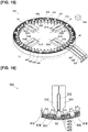
- Figure 15 is a perspective view illustrating a connecting device 300 of a winding 50 and terminal members 41 of the bus ring assembly 40 according to the fourth embodiment.
- Figure 16 is a top view illustrating the main part of Figure 15 .
- Figure 17 is a view illustrating the main part of a connecting step using the connecting device 300 illustrated in Figure 15 and Figure 16 .
- Figure 17(A) is a top view illustrating the state before the terminal member 41 of the bus ring assembly 40 is caulked to the winding 50.
- Figure 17(B) is a top view illustrating the state in which a proximal end portion 41i of the terminal member 41 is caulked and connected with respect to the winding 50.
- Figure 17(C) is a top view illustrating the state in which a distal end portion 41j of the terminal member 41 is caulked and connected with respect to the winding 50.
- the connecting device 300 comprises pairs of pressing members, right pressing members 301 and left pressing members 302, which press the proximal end portion 41i of the conductive portion 41M from both sides against the winding 50, distal end pressing members 303 that press and deforms the distal end portion 41j of the conductive portion 41M against the winding 50, and a controller 304 that respectively controls the operations of the right pressing members 301, the left pressing members 302, and the distal end pressing members 303, as illustrated in Figure 15 .
- the two pressing members, the right pressing member 301 and the left pressing member 302, are each formed in a rectangular parallelepiped shape and are configured to be capable of approaching and separating from each other in the lateral direction of Figure 16 by a linear moving stage.
- the right pressing member 301 comprises a right pressing portion 301a that protrudes in a convex shape on the side surface of the distal end portion thereof, as illustrated in Figure 17 .
- the left pressing member 302 comprises a left pressing portion 302a that protrudes in a convex shape on the side surface of the distal end portion thereof, as illustrated in Figure 17 .
- the right pressing portion 301a and the left pressing portion 302a have the same shape and are opposite each other.
- the four pairs of the right pressing member 301 and the left pressing member 302 are respectively operated in conjunction with each other and respectively connect four terminal members 41 to the winding 50 at the same time.
- the four pairs of the right pressing member 301 and the left pressing member 302 are brought close to each other so that the proximal end portions 41i of the four terminal members 41 facing radially outwardly are connected to the winding 50 and are then rotated in the circumferential direction in Figure 15 after being retracted radially inwardly by the linear moving stage. Thereafter, the four pairs of the right pressing member 301 and the left pressing member 302 are returned radially outwardly by the linear moving stage by the original distance, and respectively connect the proximal end portions 41i of four unconnected terminal members 41 to a new winding 50.
- the distal end pressing members 303 are formed in a rod shape and are configured to be movable with respect to the vertical direction in Figure 16 .
- the distal end pressing members 303 are disposed in the gaps between the pairs of pressing members, the right pressing member 301 and the left pressing member 302. Even when the pair of pressing members, the right pressing member 301 and the left pressing member 302, come closest to each other, the distal end pressing member 303 does not interfere with the side surfaces thereof, as illustrated in Figure 17(B) .
- the distal end pressing member 303 is provided with a distal end pressing portion 303a having two side-by-side concave depressions formed at the distal end portion thereof, as illustrated in Figure 17 .
- distal end pressing members 303 are arranged in an arc shape at equiangular (90°) intervals, such that the distal end portions comprising the distal end pressing portion 303a face radially outwardly, together with the pair of pressing members, the right pressing member 301 and the left pressing member 302, as illustrated in Figure 15 .
- the four sets of distal end pressing members 303 connect the distal end portions 41j of the four terminal members 41 facing radially outwardly with respect to the winding 50 and are then rotated in the circumferential direction in Figure 15 after being retracted radially inwardly by the linear moving stage, together with the pair of pressing members, the right pressing member 301 and the left pressing member 302. Thereafter, the four sets of the distal end pressing members 303 are returned radially outwardly by the linear moving stage by the original distance together with the pair of pressing members, the right pressing member 301 and the left pressing member 302, and respectively connect the distal end portions 41j of four unconnected terminal members 41 to a new winding 50.
- the controller 304 respectively controls the operations of the right pressing members 301, the left pressing members 302, and the distal end pressing members 303.
- the controller 304 comprises a ROM, a CPU, and a RAM.
- a control program related to the winding of the right pressing members 301, the left pressing members 302, and the distal end pressing members 303 is stored in the ROM (Read Only Memory).
- the CPU (Central Processing Unit) of the controller 304 controls the operations of each of the component members described above.
- Various data related to each component member under control are temporarily stored in the RAM (Random Access Memory).
- the connecting device 300 starts the connection of a terminal member 41 and a winding 50 in a state in which the winding 50 is positioned between a pair of conductive surfaces, the first conductive surface 41d1 and the second conductive surface 41d2, of the terminal member 41, as illustrated in Figure 17(A) .
- the connecting device 300 brings the right pressing portion 301a and the left pressing portion 302a close to each other to thereby press and restrain the proximal end portion 41i of the terminal member 41 toward the center from the left and right in the drawing, while deforming and pressure bonding the proximal end portion 41i to the winding 50, as illustrated in Figure 17(B) .
- the proximal end portion 41i includes the pair of conductive surfaces, the first conductive surface 41d1 and the second conductive surface 41d2, and faces the other end 41b side.
- the connecting device 300 presses and deforms a spaced portion 41h toward the center from the left and right in the drawing, so as to enfold the spaced portion 41h in the deformation of the proximal end portion 41i, and pressure bonds the spaced portion to the winding 50.
- the spaced portion 41h includes the pair of conductive surfaces, the first conductive surface 41d1 and the second conductive surface 41d2, and is spaced from the proximal end portion 41i facing the other end 41b side toward the other end 41b side. That is, the spaced portion 41h is a curved portion on the rear surface side of the terminal member 41 indicated by the broken line in Figure 17(A) .
- the connecting device 300 presses the distal end pressing member 303 toward the distal end portion 41j while the proximal end portion 41i is being sandwiched by the right pressing portion 301a and the left pressing portion 302a, to deform and pressure bond the distal end portion 41j to the winding 50, as illustrated in Figure 17(C) .
- the distal end portion 41j is a portion including the pair of conductive surfaces, the first conductive surface 41d1 and the second conductive surface 41d2, and that extends from the proximal end portion 41i, facing the other end 41b side, to the other end 41a side.
- the connecting device 300 deforms the winding 50 together with the distal end portion 41j.
- the connecting device 300 carries out pressure bonding so that the spaced portion 41h, the proximal end portion 41i, and the distal end portion 41j portions of the terminal member 41 form an annular shape that surrounds the winding 50.
- the method for connecting the terminal member 41 and the winding 50 according to the fourth embodiment described above provides actions and effects by means of the following configurations.
- the method for connecting a terminal member 41 and a winding 50 is for connecting a winding 50, and a terminal member 41 comprising a pair of conductive surfaces, a first conductive surface 41d1 and a second conductive surface 41d2, having a plate shape extending from one end 41a toward the other end 41b and provided with a front surface 41 c and a rear surface 41d, respectively projecting from the front surface 41c to the rear surface 41d side at the one end 41 a, and opposite each other along a direction that intersects the direction from the one end 41a toward the other end 41b.
- the winding 50 is positioned between a pair of opposing conductive surfaces, the first conductive surface 41d1 and the second conductive surface 41d2, and at least a portion of the pair of opposing conductive surfaces, the first conductive surface 41d1 and the second conductive surface 41d2, is pressed toward the winding 50 and deformed to be connected with the winding 50.
- the method for connecting a terminal member 41 and a winding 50 configured in this manner, it is possible to sufficiently join the terminal member 41 and the winding 50 by means of a simple method in which at least a portion of a pair of conductive surfaces, a first conductive surface 41d1 and a second conductive surface 41d2, is pressed toward the winding 50 and deformed to be connected with the winding 50.
- connection method since the terminal member 41 deforms without heating when the terminal member 41 and the winding 50 are joined, a control or a device for heating is not required. Therefore, the connection of the terminal member 41 and the winding 50 can be carried out with low-cost equipment. Moreover, since a high electric power for heating the terminal member 41 is not required, connection of the terminal member 41 and the winding 50 can be carried out at low cost. Furthermore, since the terminal member 41 is deformed without heating when the terminal member 41 and the winding 50 are joined, heat is not conducted to heat members with insufficient heat resistance. That is, a control or a device for heat dissipation and cooling is not required.
- the method for connecting a terminal member 41 and a winding 50 configured in this manner, it is possible to strongly connect the terminal member 41 to the winding 50, by deforming, and pressure bonding to the winding 50, at least the proximal end portion 41i of the terminal member 41. Furthermore, since a surface onto which the winding 50 is pressed is not required, it is possible to easily join at least the proximal end portion 41i of the terminal member 41, even if an error has occurred in the position of the winding 50.
- a distal end portion 41j which extends to the one end 41a side from the proximal end portion 41i including the pair of conductive surfaces, the first conductive surface 41d1 and the second conductive surface 41d2, and facing the other end 41b side, is deformed and connected to the winding 50.
- the method for connecting a terminal member 41 and a winding 50 configured in this manner, it is possible to strongly connect the terminal member 41 to the winding 50, by deforming, and pressure bonding to the winding 50, at least the distal end portion 41j of the terminal member 41. Furthermore, since a surface onto which the winding 50 is pressed is not required, it is possible to easily join at least the distal end portion 41j of the terminal member 41, even if an error has occurred in the position of the winding 50.
- a spaced portion 41h which is spaced from the other end 41b side from the proximal end portion 41i including the pair of conductive surfaces, the first conductive surface 41d1 and the second conductive surface 41d2, and facing the other end 41b side, is deformed toward the winding 50 and connected to the winding 50.
- the method for connecting a terminal member 41 and a winding 50 configured in this manner, it is possible to strongly connect the terminal member 41 to the winding 50, by deforming, and pressure bonding to the winding 50, at least the spaced portion 41h of the terminal member 41. Furthermore, since a surface onto which the winding 50 is pressed is not required, it is possible to easily join at least the spaced portion 41h of the terminal member 41, even if an error has occurred in the position of the winding 50.
- the bus ring 20 described in the second embodiment may be configured to use the terminal member 12 according to the modified example of the first embodiment, instead of the terminal member 21.
- the bus ring assembly 40 described in the third embodiment may be configured using a bus ring that includes the terminal member 12 according to the modified example of the first embodiment, or the bus ring 30 according to the modified example of the second embodiment.
Landscapes
- Engineering & Computer Science (AREA)
- Power Engineering (AREA)
- Manufacturing & Machinery (AREA)
- Manufacturing Of Electrical Connectors (AREA)
- Connections Effected By Soldering, Adhesion, Or Permanent Deformation (AREA)
- Insulation, Fastening Of Motor, Generator Windings (AREA)
- Manufacture Of Motors, Generators (AREA)
- Coils Or Transformers For Communication (AREA)
Abstract
Description
- The present invention relates to a method for manufacturing a terminal member, a method for connecting a terminal member and a conductive member, a terminal member and a wiring member.
- Conventionally, there is a device that connects a terminal corresponding to a terminal member, and an end portion of a conductive wire corresponding to a winding that is wound in a coil shape onto a divided core of a stator (for example, refer to Patent Document 1). In such a device, a conductive wire, and a terminal having an elongated central portion and a U-shaped bent structure for sandwiching a conductive wire at the distal end portion thereof, are press-bonded in a heated state.
- Patent Document 1: Japanese Laid-Open Patent Application No.
2013-183544 - Here, there is a demand for a manufacturing method that is capable of further improving the productivity of the terminal member by simplifying the configuration of the terminal member. In addition, there is a demand for a connection method that is capable of more easily joining a terminal member and a winding without recourse to a special treatment such as heating. Additionally, there is a demand for a terminal member with greater rigidity to prevent deformations or the like at the time of assembly. Furthermore, there is also a demand for a wiring member, which includes a terminal member, with greater rigidity, to prevent breakage or the like of the component members.
- In order to solve the problems described above, an object of the present invention is to provide a method for manufacturing a terminal member capable of significantly improving the productivity of the terminal member that is joined to a winding for electrical conduction therewith. Furthermore, another object of the present invention is to provide a method of connecting a terminal member and a winding that is capable of sufficiently joining a terminal member and a winding by means of a simple method. Furthermore, another object of the present invention is to provide a terminal member that is capable of increasing the rigidity of the entire terminal. Furthermore, another object of the present invention is to provide a highly rigid wiring member that is capable of preventing breakage of component members including a terminal member, even when stress is applied thereto.
- The method for manufacturing a terminal member according to the present invention which achieves the objects described above is a method for manufacturing a terminal member for electrical conduction with a conductive member working a workpiece having a plate shape with a first surface and a second surface extending from one end toward the other end, by cutting out a recessed portion at the one end from the first surface to the second surface. In the method for manufacturing a terminal member, the recessed portion is supported by being abutted against a supporting member, and a portion spaced from the recessed portion toward the other end side is fixed, and both side portions along the one end from the recessed portion are bent while being pressed from the first surface toward the second surface side, thereby forming, as a pair of conductive surfaces for conduction with the conductive member, second surface portions facing each other with the supporting member interposed therebetween.
- The method for connecting a conductive member and a terminal member according to the present invention which achieves the objects described above is a method for connecting a conductive member and a terminal member that has a pair of conductive surfaces having a plate shape with a first surface and a second surface extending from one end toward the other end, respectively, and projecting at the one end from the first surface to a side with the second surface, and opposite each other along a direction that intersects a direction from the one end toward the other end. In the method for connecting a terminal member and a conductive member, the conductive member is positioned between a pair of opposing conductive surfaces, and at least a portion of the pair of opposing conductive surfaces is pressed toward the conductive member and deformed to be connected with the conductive member.
- The terminal member according to the present invention which achieves the objects described above is joined to a conductive member for electrical conduction therewith. The terminal member comprises a conductive portion and a supporting portion. The conductive portion comprises a pair of conductive surfaces having a plate shape with a first surface and a second surface extending from one end toward the other end, respectively projecting from the first surface to a side with the second surface, and opposite each other along a direction that intersects a direction from one end toward the other end. The supporting portion extends from the conductive portion toward the other end side and supports the conductive portion. Here, the supporting portion has a longer width along the direction in which the pair of the conductive surfaces face each other than that of the conductive portion.
- The wiring member according to the present invention which achieves the objects described above comprises a terminal member and a conductive band member. The terminal member is provided with a conductive portion and a supporting portion. The conductive portion comprises a pair of conductive surfaces having a plate shape with a first surface and a second surface extending from one end toward the other end, respectively, and projecting from the first surface to a side with the second surface, and opposed to each other along a direction that intersects a direction from the one end toward the other end. The supporting portion extends from the conductive portion toward the other end side and supports the conductive portion. Here, the supporting portion has a longer width along the direction in which the pair of the conductive surfaces face each other than that of the conductive portion. The conductive band member comprises an elongated shape having conductivity, joins a plurality of terminal members along a longitudinal direction at a predetermined interval, and conducts the electric power supplied from outside to each of the terminal members.
-
- [
Figure 1 ] illustrates the terminal member according to a first embodiment; (A) is a perspective view showing the terminal member from one side, and (B) is a perspective view showing the terminal member from the other side. - [
Figure 2 ] illustrates the method for manufacturing a terminal member using the manufacturing device according to the first embodiment, in a state in which a workpiece is attached to the manufacturing device; (A) is a perspective view illustrating said state, and (B) is a top view illustrating said state. - [
Figure 3 ] illustrates, followingFigure 2 , a state in which the workpiece is press-worked by the manufacturing device, (A) is a perspective view illustrating said state, and (B) is a top view illustrating said state. - [
Figure 4 ] is a perspective view illustrating a terminal member according to a modified example of the first embodiment. - [
Figure 5 ] is a perspective view illustrating a bus ring according to the second embodiment. - [
Figure 6 ] is an exploded perspective view illustrating the main parts of the bus ring ofFigure 5 . - [
Figure 7 ] is a perspective view illustrating a bus ring according to a modified example of the second embodiment. - [
Figure 8 ] is an exploded perspective view illustrating the main parts of the bus ring ofFigure 7 . - [
Figure 9 ] is a perspective view illustrating a bus ring assembly according to a third embodiment. - [
Figure 10 ] is a top view illustrating the main parts of the bus ring assembly ofFigure 9 . - [
Figure 11 ] is a view illustrating the main part of the bus ring assembly ofFigure 9 , which is a portion thereof, in a state in which insulating band members are bonded to both sides in the radial direction of a U-phase conductive band member; (A) is a perspective view illustrating said main part, and (B) is a side view illustrating said main part. - [
Figure 12 ] is a perspective view illustrating a manufacturing device of the bus ring assembly according to a third embodiment. - [
Figure 13 ] is a view illustrating a state in which a conductive band member is wound around the main frame by the manufacturing device ofFigure 12 ; (A) is a side view illustrating the state before winding, and (B) is a side view showing the state after winding. - [
Figure 14 ], followingFigure 13 , is a view illustrating a state in which an insulating band member is wound around and bonded to a conductive band member; (A) is a side view illustrating the state before winding, and (B) is a side view illustrating the state after winding. - [
Figure 15 ] is a perspective view illustrating a connecting device of a winding and terminal members of the bus ring assembly according to the fourth embodiment. - [
Figure 16 ] is a top view illustrating the main part ofFigure 15 . - [
Figure 17 ] is a view illustrating the main part of a connecting step using the connecting device illustrated inFigure 15 and Figure 16 ; (A) is a top view illustrating the state before caulking of the terminal member of the bus ring assembly with respect to the winding, (B), following (A), is a top view illustrating the state in which a proximal end portion of the terminal member is caulked and connected with respect to the winding, and (C), following (B), is a top view illustrating the state in which a distal end portion of the terminal member is caulked and connected with respect to the winding. - The first to the fourth embodiments according to the present invention will be described below, with reference to the appended drawings. In the explanations of the drawings, the same elements have been assigned the same reference symbols, and redundant explanations have been omitted. The sizes and ratios of the members in the drawing are exaggerated for the sake of convenience of explanation and may differ from the actual sizes and ratios.
- First, the configuration of a
terminal member 11 manufactured using amanufacturing device 100 will be described with reference toFigure 1 . -
Figure 1 is a view illustrating theterminal member 11 according to the first embodiment.Figure 1(A) is a perspective view illustrating theterminal member 11 from one side.Figure 1(B) is a perspective view illustrating theterminal member 11 from the other side. - The
terminal member 11 is a terminal joined to a winding 50 for electrical conduction therewith. In one embodiment, theterminal member 11 configures, for example, a bus ring (Figure 5 ) according to the second embodiment, together with a conductive band member. Theterminal member 11 comprises aconductive portion 11M that joins the winding 50 (Figure 15 ) and a supportingportion 11N that supports theconductive portion 11M. Theterminal member 11 comprises a plate shape extending from oneend 11a toward theother end 11b and is provided with afront surface 11c and arear surface 11d. Theterminal member 11 is formed by being bent into an L shape such that the side with therear surface 11d faces inward, such that the supportingportion 11N and theconductive portion 11M bound the bent portion. Theterminal member 11 is made from a conductive metal, such as copper. - The conductive portion 11Mcomprises a pair of conductive surfaces (first conductive surface 11d1 and second conductive surface 11d2) that are branched in two from the side with the supporting
portion 11N toward the oneend 11a, and sandwich the winding 50. The first conductive surface 11d1 and the second conductive surface 11d2 respectively project from thefront surface 11c of theconductive portion 11M toward the side with therear surface 11d, and face each other. The portion that includes the first conductive surface 11d1 and that faces the side with theother end 11b, and the portion that includes the second conductive surface 11d2 and that faces the side with theother end 11b are respectively extended so as to be inclined from the supportingportion 11N toward the side with theconductive portion 11M. This inclined portion is configured from a portion bent in a crest fold shape (first deformed portion 11 p) and a portion bent in a trough fold shape (second deformed portion 11q). The thickness of the portion including the first conductive surface 11d1 along the oneend 11a (h1) and the thickness of the portion including the second conductive surface 11d2 along the oneend 11a (h1 and h2) are both the same as the thickness (h3) between thefront surface 11c and therear surface 11d in the supportingportion 11N. - The supporting
portion 11N extends from theconductive portion 11M toward the side with theother end 11b and supports theconductive portion 11M. The supportingportion 11N is also the portion that is joined to the conductive band member in, for example, the bus ring (Figure 5 ) according to the second embodiment. The supportingportion 11N has a longer lateral width along the direction in which the pair of conductive surfaces, i.e., the first conductive surface 11d1 and the second conductive surface 11d2, face each other, than the lateral width of theconductive portion 11M. - The
terminal member 11 according to the first embodiment described above provides actions and effects by means of the following configurations. - The
terminal member 11 is joined to the winding 50 for electrical conduction therewith. Theterminal member 11 comprises aconductive portion 11M and a supporting portion 11N.Theconductive portion 11M comprises a pair of conductive surfaces (first conductive surface 11d1 and second conductive surface 11d2) having a plate shape extending from oneend 11a toward theother end 11b and provided with afront surface 11c and arear surface 11d, respectively projecting from the side with thefront surface 11c to the side with therear surface 11d, and opposite each other along a direction that intersects direction from the oneend 11a toward theother end 11b. The supportingportion 11N extends from theconductive portion 11M toward the side with theother end 11b and supports theconductive portion 11M. Here, the supportingportion 11N has a longer width along the direction in which the pair of conductive surfaces, the first conductive surface 11d1 and the second conductive surface 11d2, face each other, than that of theconductive portion 11M. - According to a
terminal member 11 configured in this manner, the width of the supportingportion 11N is thicker than the width of theconductive portion 11M. Therefore, since theterminal member 11 is able to sufficiently support theconductive portion 11M that joins the winding 50 by means of the supportingportion 11N having a thicker width than theconductive portion 11M, it is possible to increase the rigidity of the entire terminal. - Furthermore, the
terminal member 11 is formed such that the portion that includes the first conductive surface 11d1 and that the side with faces theother end 11b, and the portion that includes the second conductive surface 11d2 and that the side with faces theother end 11b are respectively extended so as to be inclined from the supportingportion 11N toward the side with theconductive portion 11M, with respect to therear surface 11d. - According to a
terminal member 11 configured in this manner, the space between the supportingportion 11N and theconductive portion 11M is connected by an inclined portion, and it is possible to absorb, while transmitting to the supportingportion 11N, stress that is applied, for example, from theconductive portion 11M that joins the winding 50 to the supportingportion 11N, by the inclined portion. Therefore, theterminal member 11 can increase the rigidity of the entire terminal, from theconductive portion 11M to the supportingportion 11N. - Furthermore, the
terminal member 11 is formed such that the space between the supportingportion 11N and theconductive portion 11M is connected by a portion bent in a crest fold shape (first deformed portion 11p) and a portion bent in a trough fold shape (second deformed portion 11q). - According to a
terminal member 11 configured in this manner, it is possible to accurately form a terminal including a pair of conductive surfaces, the first conductive surface 10d1 and the second conductive surface 10d2, and to increase the rigidity of the entire terminal, by the crest fold shape and the trough fold shape between the supportingportion 11N and theconductive portion 11M. - Furthermore, the
terminal member 11 is formed such that the thickness of the portion of theconductive portion 11M that includes the first conductive surface 11d1 along the oneend 11a (h1) and the thickness of the portion that includes the second conductive surface 11d2 along the oneend 11a (h2) to be respectively equal to or greater than the thickness (h3) between thefront surface 11c and therear surface 11d in the supportingportion 11N. - According to a
terminal member 11 configured in this manner, it is possible to make the rigidity of the portion on the distal end side including the first conductive surface 11d1 (conductive portion 11M including the first conductive surface 11d1) and of the portion on the distal end side including the second conductive surface 11d2 (conductive portion 11M including the second conductive surface 11d2) to be respectively equal to or greater than the rigidity of the proximal end side portion (supportingportion 11N). - Furthermore, the
terminal member 11 is formed in an L shape from the supportingportion 11N to theconductive portion 11M, such that the side with therear surface 11d faces inward. - According to a
terminal member 11 configured in this manner, it is possible to form the entire terminal to be smaller compared with when the terminal is formed extending linearly from the supportingportion 11N to theconductive portion 11M. Furthermore, theterminal member 11 comprises a pair of conductive surfaces, the first conductive surface 11d1 and the second conductive surface 11d2, on the inward side (inner side) of the L shaped bend. Therefore, in theterminal member 11, it is possible to avoid interference between the pair of conductive surfaces, the first conductive surface 11d1 and the second conductive surface 11d2, and a structure disposed on the outward side (outer side) of theterminal member 11. - Next, the method of manufacturing the
terminal member 11 using themanufacturing device 100 as well as themanufacturing device 100 will be described with reference toFigure 2 andFigure 3 . -
Figure 2 is a view illustrating the method for manufacturing aterminal member 11 using themanufacturing device 100 according to the first embodiment, showing the state in which theworkpiece 10 is attached to themanufacturing device 100.Figure 2(A) is a perspective view showing said state.Figure 2(B) is a top view showing said state. FollowingFigure 2 ,Figure 3 shows a state in which theworkpiece 10 is press-worked by themanufacturing device 100.Figure 3(A) is a perspective view showing said state.Figure 3(B) is a top view showing said state. - The method for manufacturing the
terminal member 11 is for the manufacture of aterminal member 11 for electrical conduction with a winding 50, by working a workpiece (workpiece 10). Theworkpiece 10 has a plate shape extending from oneend 10a toward theother end 10b, and has afront surface 10c and arear surface 10d, and which is provided, at the oneend 10a, with a recessedportion 10e that is cut out and recessed from thefront surface 10c to therear surface 10d. Themanufacturing device 100 embodies the method for manufacturing theterminal member 11 described above. - The configuration of the
manufacturing device 100 for manufacturing theterminal member 11 will now be described. - The
manufacturing device 100 comprises a supportingmember 101 that supports theworkpiece 10 at the recessedportion 10e, a lower supportingmember 102 and an upper supportingmember 103 that sandwich and fix a fixingregion 10f of the workpiece 10 from above and below, aright pressing member 104 and a left pressingmember 105 that press a pair of pressedregions 10g of theworkpiece 10, and acontroller 106 for controlling the working of theworkpiece 10, as illustrated inFigure 2 . - The supporting
member 101 supports theworkpiece 10 at the recessedportion 10e. The supportingmember 101 corresponds to a so-called nest. The supportingmember 101 has a plate shape, and is disposed along the vertical direction so as to stand upright. One side surface (right side inFigure 2(B) ) of the supportingmember 101 in the short side direction is curved in a semicircular shape to match the shape of the recessedportion 10e of theworkpiece 10 to be abutted there against. The recessedportion 10e of theworkpiece 10 is inserted and fitted to the portion of the supportingmember 101 that is curved in a semicircular shape. - The lower supporting
member 102 and the upper supportingmember 103 sandwich and fix a fixingregion 10f of the workpiece 10 (region spaced from the recessedportion 10e of theworkpiece 10 toward the side with theother end 10b) from above and below. The lower supportingmember 102 has a plate shape, and is disposed along the horizontal direction. The lower supportingmember 102 is primarily formed by cutting out both sides of the end portion on one side along the longitudinal direction (left side inFigure 2(B) ) to match the shape of the fixingregion 10f of theworkpiece 10. The upper supportingmember 103 is shaped in the same manner as the lower supportingmember 102. The upper supportingmember 103 and the lower supportingmember 102 are respectively spaced from the opposing supportingmember 101 in the horizontal direction (left side inFigure 2(B) ) by a length corresponding to the portion of theunpressed region 10h of the workpiece 10 (region of the portion of theworkpiece 10 to be bent facing the side with theother end 10b), as illustrated inFigure 2(B) . - The
right pressing member 104 and theleft pressing member 105 press the pair of pressedregions 10g of the workpiece 10 (regions further toward the two sides along the oneend 10a than the recessedportion 10e). Theright pressing member 104 and theleft pressing member 105 correspond to so-called punches. Theright pressing member 104 has a rectangular parallelepiped shape and presses the pressedregion 10g on the lower side of theworkpiece 10 shown inFigure 2(B) of the pair of pressedregions 10g. Theright pressing member 104 maintains a state of being spaced from the supportingmember 101 with respect to the horizontal direction along the oneend 10a (lower side inFigure 2(B) ) by the thickness of the workpiece 10 (h3). Theright pressing member 104 is moved in the vertical direction by a single-axis linear moving stage. - The
left pressing member 105 has the same shape as theright pressing member 104. Theleft pressing member 105 presses the pressedregion 10g on the upper side of theworkpiece 10 shown inFigure 2(B) of the pair of pressedregions 10g. Theleft pressing member 105 maintains a state of being spaced from the supportingmember 101 with respect to the horizontal direction along the oneend 10a (upper side inFigure 2(B) ) by the thickness of the workpiece 10 (h3). Theleft pressing member 105 is moved in the vertical direction together with theright pressing member 104 by the single-axis linear moving stage. - The
right pressing member 104 and theleft pressing member 105 may be configured as one member. Specifically, for example, the top and bottom of a pressing member formed in a U shape may be disposed upside down, and the distal end, which is branched in two, may be configured as a pair of pressing portions (right pressing portion and left pressing portion). - The
controller 106 controls the working of theworkpiece 10. Thecontroller 106 controls the operation of the linear moving stage on which theright pressing member 104 and theleft pressing member 105 are mounted. Thecontroller 106 comprises a ROM, a CPU, and a RAM. A control program related to the working of theworkpiece 10 is stored in the ROM (Read Only Memory). The control program contains information related to the movement distance, the movement speed and the like of theright pressing member 104 and theleft pressing member 105. The CPU (Central Processing Unit) of thecontroller 106 controls the driving of the linear moving stage. Various data related to the linear moving stage under control are temporarily stored in the RAM (Random Access Memory). The data are, for example, related to the movement distance of the linear moving stage. - The method for manufacturing the
terminal member 11 using themanufacturing device 100 will now be described. -
Figure 2 illustrates the state in which theworkpiece 10 is attached to themanufacturing device 100 before theworkpiece 10 is worked. The supportingmember 101 supports the recessedportion 10e of theworkpiece 10 in contact therewith. The lower supportingmember 102 and the upper supportingmember 103 sandwich and fix the fixingregion 10f spaced from the recessedportion 10e of theworkpiece 10 toward the side with theother end 10b. Theright pressing member 104 and theleft pressing member 105 are on standby above the pair of pressedregions 10g further toward the two sides along the oneend 10a than the recessedportion 10e. -
Figure 3 illustrates the state in which theworkpiece 10 is press-worked using themanufacturing device 100 after theworkpiece 10 is worked. Theright pressing member 104 and theleft pressing member 105 cause the pair of pressedregions 10g of theworkpiece 10 to be placed along the supportingmember 101 and press and bend the pair of pressed regions from thefront surface 10c toward the side with therear surface 10d only once. Therear surface 10d portions facing each other with the supportingmember 101 interposed therebetween become a pair of conductive surfaces that face each other (first conductive surface 10d1 and second conductive surface 10d2). - Here, the
right pressing member 104 and theleft pressing member 105 press portions of theworkpiece 10 to be bent, excluding the portion that faces the side with theother end 10b (unpressed region 10h). Theunpressed region 10h deforms accompanying the bending of the adjacent pair of pressedregions 10g. Therefore, since the side with the oneend 10a spaced from the fixingregion 10f is more greatly bent than the side with theother end 10b adjacent to the fixingregion 10f, which is fixed and is not easily deformed, theunpressed region 10h of theworkpiece 10 is bent to be inclined from the side with theother end 10b toward the side with the oneend 10a. - In addition, the
right pressing member 104 and theleft pressing member 105 bend theworkpiece 10, with each of the one end portion of theunpressed region 10h adjacent to the fixingregion 10f (firstdeformed portion 10p), and the other end portion of theunpressed region 10h adjacent to the pair of pressedregions 10g (seconddeformed portion 10q) as a boundary. Since the firstdeformed portion 10p is pushed down along the edge of the fixingregion 10f, which is fixed and is not easily deformed, the first deformed portion is bent in a crest fold shape. Since the seconddeformed portion 10q is pressed against the supportingmember 101, the second deformed portion is bent in a trough fold shape along the edges of the pair of pressedregions 10g, which are easily deformed. Therefore, theunpressed region 10h of theworkpiece 10 is bent such that a crest fold shape and a trough fold shape are continuous from theother end 10b toward the side with the oneend 10a. - The method for manufacturing a
terminal member 11 according to the first embodiment described above provides actions and effects by means of the following configurations. - The method for manufacturing a
terminal member 11 is used for manufacturing aterminal member 11 for electrical conduction with a conductive member (a winding 50) by working a workpiece (workpiece 10) which comprises a plate shape extending from oneend 10a toward theother end 10b and provided with a first surface (afront surface 10c) and a second surface (arear surface 10d), and which is provided, at the oneend 10a, with a recessedportion 10e that is cut out and recessed from thefront surface 10c to therear surface 10d. In this method for manufacturing theterminal member 11, the recessedportion 10e is supported by being abutted against a supportingmember 101, a portion (a fixingregion 10f) spaced from the recessedportion 10e toward the side with theother end 10b is fixed, and both side portions (a pair of pressedregions 10g) along the oneend 10a from the recessedportion 10e are bent while being pressed from thefront surface 10c toward the side with therear surface 10d, thereby forming, a pair of conductive surfaces (the first conductive surface 10d1 and the second conductive surface 10d2) for conduction with the winding 50, therear surface 10d of the portions facing each other with the supportingmember 101 interposed therebetween. - According to the method for manufacturing a
terminal member 11 configured in this manner, a pair of conductive surfaces, a first conductive surface 10d1 and a second conductive surface 10d2, are formed by pressing a pair of pressedregions 10g of theworkpiece 10 along the supportingmember 101. That is, by using this method for manufacturing aterminal member 11, it is possible to form a pair of conductive surfaces, the first conductive surface 10d1 and the second conductive surface 10d2, which face each other, by means of a single pressing based on the supportingmember 101. Therefore, this method for manufacturing aterminal member 11 is capable of greatly improving the productivity of theterminal member 11 to be joined to a winding 50 for electrical conduction therewith. - In addition, according to the method for manufacturing a
terminal member 11 configured in this manner, it is possible to make the width of the portion (the supportingportion 11N) positioned on the side with theother end 11b and supporting the pair of conductive surfaces (the first conductive surface 11d1 and the second conductive surface 11d2) in theterminal member 11 to be manufactured to be thicker than the width of the portion (theconductive portion 11M) positioned on the side with the oneend 11a and including the pair of conductive surfaces (the first conductive surface 11d1 and the second conductive surface 11d2). Therefore, this method for manufacturing aterminal member 11 is capable of providing great rigidity to theterminal member 11 to be manufactured. In particular, if theterminal member 11 to be manufactured is highly rigid, so that even when said terminal member interferes with other component members, misalignment does not readily occur; therefore, it is possible to maintain positional accuracy, and handling becomes easy. - Additionally, according to the method for manufacturing a
terminal member 11 configured in this manner, theworkpiece 10 to be used for working comprises a plate shape having only the recessedportion 10e on the oneend 10a, and breaking and cutting are not performed when working theworkpiece 10. That is, the yield of theworkpiece 10 itself to be used for working is high, and material is not discarded during working of theworkpiece 10. Therefore, the method for manufacturing aterminal member 11 is capable of reducing the material costs required for theworkpiece 10. - Furthermore, in this method for manufacturing a
terminal member 11, the pressing of the portions of theworkpiece 10 to be bent, excludes the portion (theunpressed region 10h) facing the side with theother end 11b. - According to the method for manufacturing a
terminal member 11 configured in this manner, the pair of pressedregions 10g are pressed toward the side with therear surface 10d across theunpressed region 10h. With this configuration, it is possible to bend theunpressed region 10h adjacent to the pair of pressedregions 10g to be inclined from the side with faces theother end 11b adjacent to the fixingregion 10f toward the side with the oneend 10a spaced from the fixingregion 10f, in a single pressing. That is, by using this method for manufacturing aterminal member 11, while theunpressed region 10h is deformed accompanying the bending of the adjacent pair of pressedregions 10g, the oneend 10a side spaced from the fixingregion 10f is more readily bent than the side with faces theother end 11b that is adjacent to the fixingregion 10f, which is fixed and does not readily deform. Accordingly, theunpressed region 10h is relatively largely bent so as to be inclined from the side with faces theother end 11b toward the oneend 10a side. As a result, it is possible to tilt and connect the space between the pair of pressedregions 10g and the fixingregion 10f by theunpressed region 10h, which is inclined from the side with faces theother end 11b toward the side with the oneend 10a. Therefore, this method for manufacturing aterminal member 11 is capable of imparting great rigidity to theentire terminal member 11 to be manufactured by the inclined portion (theunpressed region 10h) that is formed between the proximal end side (the side with the fixingregion 10f) and the distal end side (the side with the pair of the pressedregions 10g). - Additionally, according to the method for manufacturing a
terminal member 11 configured in this manner, it is possible to bend theworkpiece 10, with each of the one end portion of theunpressed region 10h adjacent to the fixingregion 10f (firstdeformed portion 10p), and the other end portion of theunpressed region 10h adjacent to the pair of pressedregions 10g (seconddeformed portion 10q) as a boundary, by a single pressing. With this configuration, it is possible to bend the firstdeformed portion 10p in a crest fold shape along the edge of the fixingregion 10f and to bend the seconddeformed portion 10q in a trough fold shape along the edges of the pair of pressedregions 10g abutting the supportingmember 101, as seen from thefront surface 10c toward therear surface 10d side of theworkpiece 10. That is, by using this method for manufacturing aterminal member 11, it is possible to bend the firstdeformed portion 10p into a crest fold shape by pressing down along the edge of the fixingregion 10f, which is fixed and is not easily deformed. At the same time, it is possible to bend the seconddeformed portion 10q in a trough fold shape along the edges of the pair of pressedregions 10g, which are easily deformed, by pressing against the supportingmember 101. Therefore, this method for manufacturing aterminal member 11 is capable of accurately forming theterminal member 11, which includes a pair of conductive surfaces, a first conductive surface 10d1 and a second conductive surface 10d2, while providing great overall rigidity to theterminal member 11 to be manufactured, by bending theunpressed region 10h of theworkpiece 10 such that the crest fold shape and the trough fold shape are continuous from theother end 10b toward the oneend 10a side. In particular, according to such a method for manufacturing aterminal member 11, since it is possible to suppress the occurrence of spring back by connecting a crest fold shape and a trough fold shape, it becomes possible to prevent the shape of theterminal member 11 from deforming after manufacture. - Furthermore, in this method for manufacturing a
terminal member 11, the pressing of portions (the pair of the pressedregions 10g) of theworkpiece 10 to be bent, which are spaced respectively from the supportingmember 101 along both sides of the oneend 10a by a distance equal to or greater than the thickness (h3) between thefront surface 10c and therear surface 10d. - According to the method for manufacturing a
terminal member 11 configured in this manner, it is possible to form the thickness (h1) along the oneend 10a of the distal end side that includes the first conductive surface 10d1 and the thickness (h2) along the oneend 10a of the distal end side that includes the second conductive surface 10d2, to be respectively equal to or greater than the thickness (h3) between thefront surface 10c and therear surface 10d on the proximal end side. Therefore, this method for manufacturing aterminal member 11 is capable of providing to each of the distal end side portion, including the first conductive surface 11d1 and the distal end side portion including the second conductive surface 11d2 the same or greater rigidity than that of the proximal end side portion. - In the
terminal member 12, a pair of conductive surfaces, a first conductive surface 12d1 and a second conductive surface 12d2, project in the opposite direction (upward) to theconductive portion 11M of theterminal member 11 described in the first embodiment. - The configuration of the
terminal member 12 will be described with reference toFigure 4 . -
Figure 4 is a perspective view illustrating aterminal member 12 according to a modified example of the first embodiment. - The
terminal member 12 is formed bent into an L shape from a supportingportion 12N to aconductive portion 12M, such that thefront surface 12c side faces inward. With such aterminal member 12, in the same manner as theterminal member 11, aworkpiece 10 is worked by amanufacturing device 100 to form a pair of conductive surfaces, a first conductive surface 12d1 and a second conductive surface 12d2. Thereafter, theterminal member 12 is formed by being bent into an L shape in the direction opposite to that of theterminal member 11, such that thefront surface 12c side faces inward, bounded by the supportingportion 12N and theconductive portion 12M. - The
terminal member 12 according to the modified example of the first embodiment provides actions and effects by means of the following configurations, in addition to the actions and effects of theterminal member 11 according to the first embodiment. - The
terminal member 12 is formed bent into an L shape from the supportingportion 12N to theconductive portion 12M, such that thefront surface 12c side faces inward. - The
terminal member 12 configured in this manner comprises a pair of conductive surfaces, the first conductive surface 12d1 and the second conductive surface 12d2, on the outward side (outer side) of the L shaped bend. Therefore, with theterminal member 12, it is possible to avoid interference between the pair of conductive surfaces, the first conductive surface 12d1 and the second conductive surface 12d2, and a structure positioned on the inward side (inner side) of the terminal member 12 (for example, amain frame 212 of themanufacturing device 200 of thebus ring assembly 40 according to the third embodiment, described below). - The
bus ring 20 is a wiring member that causes electric power supplied from the outside to flow through a plurality ofwindings 50. - The configuration of the
bus ring 20 will be described with reference toFigure 5 and Figure 6 . -
Figure 5 is a perspective view illustrating abus ring 20 according to the second embodiment.Figure 6 is an exploded perspective view illustrating the main parts of thebus ring 20 ofFigure 5 . - The
bus ring 20 comprisesterminal members 21 and aconductive band member 22. - The
terminal members 21 have the same configuration as theterminal member 11. Theterminal members 21 are illustrated by simplifying the outer shape of theterminal member 11. - The
conductive band member 22 conducts electric power supplied from the outside to each of theterminal members 21. Theconductive band member 22 is made from a conductive metal, such as copper. Theconductive band member 22 has an elongated shape and is curved into an arc shape. Both ends of theconductive band member 22 in the longitudinal direction are spaced. Theconductive band member 22 joins a plurality ofterminal members 21 to the inner perimeter surface along the longitudinal direction thereof at a predetermined interval. Each of theterminal members 21 is provided such that the distal end side of theconductive portion 21M thereof faces the radially inward direction of theconductive band member 22. Theconductive band member 22 and theterminal members 21 are joined to each other by the application of ultrasonic waves to the abutting portions to generate vibrations and thus frictional heat, locally melting the abutting portions. - The
bus ring 20 according to the second embodiment described above provides actions and effects by means of the following configurations. - The
bus ring 20 comprisesterminal members 21 and aconductive band member 22. Eachterminal member 21 is provided with aconductive portion 21M comprising a pair of conductive surfaces, a first conductive surface 21d1 and a second conductive surface 21d2, having a plate shape extending from oneend 21a toward the other end 21b and provided with afront surface 21c and arear surface 21d, respectively projecting from thefront surface 21c to therear surface 21d side, and opposite each other along a direction that intersects the direction from the oneend 21a toward the other end 21b, and with a supportingportion 21N extending from theconductive portion 21M toward the other end 21b side and supporting theconductive portion 21M, and the width of the supportingportion 21N along the direction in which the pair of conductive surfaces, the first conductive surface 21d1 and the second conductive surface 21d2, face each other is wider than that of theconductive portion 21M. Theconductive band member 22 comprises an elongated shape, which joins a plurality ofterminal members 21 along the longitudinal direction at predetermined intervals, and conducts electric power supplied from the outside to each of theterminal members 21. - With respect to the
terminal member 21 of abus ring 20 configured in this manner, the width of the supportingportion 21N is greater than the width of theconductive portion 21M. That is, since theterminal members 21 provided to thebus ring 20 are able to sufficiently support theconductive portion 21M that joins the winding 50 by means of the supportingportion 21N having a greater width than theconductive portion 21M, it is possible to increase the rigidity of the entire terminal. Therefore, even if stress is applied to theterminal members 21 or theconductive band member 22 at the time that the winding 50 is joined to theterminal members 21, or after the winding 50 is joined to theterminal members 21, thebus ring 20 is able to prevent the breakage thereof. - The radial thickness of the
bus ring 30 is formed to be less than that of thebus ring 20 described in the second embodiment. - The configuration of the
bus ring 30 will be described with reference toFigure 7 and Figure 8 . -
Figure 7 is a perspective view illustrating abus ring 30 according to a modified example of the second embodiment.Figure 8 is an exploded perspective view illustrating the main parts of thebus ring 30 ofFigure 7 . - The
bus ring 30 comprisesterminal members 31 and aconductive band member 32. - Each
terminal member 31 has the same specifications as theterminal member 21 except for the shape of the supportingportion 31N. The supportingportion 31N is formed such that the length thereof along the longitudinal direction (vertical direction illustrated inFigure 7 ) is half the length along the longitudinal direction of the supportingportion 21N of theterminal member 21. In the supportingportion 31N, ajoint portion 31t is formed by partially reducing the thickness of thefront surface 31c side (radially outward side shown inFigure 7 ) of the portion that is joined to theconductive band member 32. Since thejoint portion 31t is formed by reducing the thickness of only the lower portion along the longitudinal direction of the supportingportion 31N (vertical direction shown inFigure 7 ) and the thickness of the upper portion is not changed, theterminal member 31 maintains overall strength. - In the
conductive band member 32, thejoint portion 32t is formed by reducing the thickness of the portion that is joined to theterminal member 31. Since thejoint portion 32t is formed by reducing the thickness of only the upper portion along the short side direction (vertical direction shown inFigure 7 ) and the thickness of the lower portion is not changed, theconductive band member 32 maintains overall strength. - The
bus ring 30 according to the modified example of the second embodiment described above provides actions and effects by means of the following configurations. - In the
bus ring 30, the thickness of thejoint portion 31t of theterminal member 31 that is joined to theconductive band member 32 is formed to be less than the thickness of the portion surrounding thejoint portion 31t and/or the thickness of thejoint portion 32t of theconductive band member 32 that is joined to theterminal member 31 is formed to be less than the thickness of the portion surrounding thejoint portion 32t. - With reference to a
bus ring 30 configured in this manner, when a plurality (for example, four: N phase, U phase, V phase, and W phase) of bus rings are stacked, it is possible to reduce the gaps between adjacent bus rings 30, compared with the gaps between adjacent bus rings 20. Therefore, thebus ring 30 is capable of improving the stacking efficiency when a plurality thereof is laminated. - The
bus ring 30 is formed such that the sum of the thickness of thejoint portion 31t of theterminal member 31 and the thickness of thejoint portion 32t of theconductive band member 32 is equal to or less than the thickness of the portion around thejoint portion 31t of theterminal member 31, and/or equal to or less than the thickness of the portion around thejoint portion 32t of theconductive band member 32. - With reference to a
bus ring 30 configured in this manner, when a plurality (for example, four: N phase, U phase, V phase, and W phase) of bus rings are stacked, it is possible to eliminate the gaps between adjacent bus rings 30. Therefore, thebus ring 30 is capable of maximizing the stacking efficiency when a plurality thereof is laminated. - The
bus ring assembly 40 is a power distribution assembly that causes electric power supplied from the outside to flow through a plurality ofwindings 50 of the U phase, V phase, and N phase. Themanufacturing device 200 can be used to easily manufacture thebus ring assembly 40. - First, the configuration of a
bus ring assembly 40 manufactured using themanufacturing device 200 will be described with reference toFigures 9-11 . -
Figure 9 is a perspective view illustrating abus ring assembly 40 according to the third embodiment.Figure 10 is a top view illustrating the main parts of thebus ring assembly 40 ofFigure 9 .Figure 11 is a view illustrating the main part of thebus ring assembly 40 ofFigure 9 , which is a portion thereof, in a state in which an insulatingband member 44P and an insulating band member 44Q are bonded to both sides in the radial direction of a U-phaseconductive band member 42U.Figure 11(A) is a perspective view showing said main part.Figure 11(B) is a side view showing said main part. - The
bus ring assembly 40 comprises bus rings havingterminal members 41 andconductive band members 42, high-voltage members 43 for supplying electric power from a three-phase AC power source to theconductive band members 42, and insulatingband members 44 for insulating between adjacent bus rings. - The bus rings have
terminal members 41 andconductive band members 42. Theterminal members 41 have the same specifications as theterminal members 21. Theconductive band members 42 have the same specifications as theconductive band member 22. The bus rings are configured from four phases: U phase, V phase, W phase, and N phase. - The U-phase, V-phase, and W-phase bus rings supply electric power supplied from a three-phase AC power source to the winding 50, via the high-voltage members 43, the
conductive band members 42, and theterminal members 41. Eachterminal member 41 is connected to one end of the winding 50 (Figure 15 ). The winding 50 is configured by being wound in a coil shape (not shown) with respect to an insulator that covers the slot portion of the stator of a stator assembly. The U-phase bus ring hasterminal members 41U andconductive band members 42U. The V-phase bus ring hasterminal members 41V andconductive band members 42V. The W-phase bus ring hasterminal members 41W andconductive band members 42W. - The N-phase bus ring corresponds to ground for the U-phase, V-phase, and W-phase bus rings. The N-phase bus ring has
terminal members 41N andconductive band members 42N. The N-phase bus ring connects theterminal member 41N to the other end of the winding 50. - The bus rings are wound radially outwardly in the order of N phase, U phase, V phase, and W phase, as illustrated in
Figure 10 . Therefore, theterminal members 41 are configured such that the length along the radial direction of the conductive portion becomes longer in the order ofterminal members terminal members 41 are arranged concentrically. - The high-voltage members 43 supply electric power from a three-phase AC power source to the
conductive band members 42. The high-voltage members 43 are formed in an elongated shape, and the proximal end sides thereof are joined to the upper ends of theconductive band members 42 shown inFigure 9 . The high-voltage members 43 are extended so as to project radially outwardly from theconductive band members 42. A plurality of locations of the high-voltage members 43 from the proximal end side to the distal end side are bent downward inFigure 9 . Wires of the three-phase AC power source are connected via through-holes formed on the distal end sides of the high-voltage members 43. The U-phase, V-phase, and W-phase high-voltage members conductive band members Figure 9 . - The insulating
band members 44 provide insulation between adjacent bus rings. The insulatingband members 44 are made from an insulating material, for example, and are formed in an elongated shape. The insulatingband members 44 are not made from molding resin or the like, and thus can be configured with a thickness of several tens of µm. The short side direction width of the insulatingband members 44 is longer than that of the insulatingband member 42. With respect to the short side direction thickness h4 of theconductive band member 42, the insulatingband member 44 has a thickness h5 that is extended downward by a thickness h6 and extended upward by a thickness h7, as illustrated inFigure 11(B) . An insulatingband member 44P is laminated between theconductive band members Figure 10 . Similarly, an insulating band member 44Q is laminated between theconductive band members band member 44R is laminated between theconductive band members band member 44S is laminated radially outwardly with respect to theconductive band member 42W. - The insulating
band members band members 44. That is, the insulatingband members band member 44S is provided with an adhesive member on the radially inner side. The adhesive member is, for example, a silicone-based adhesive and is applied on one surface of the insulatingband member 44S. That is, the insulatingband member 44S is configured like a single-sided adhesive tape having insulating properties. - Next, the method of manufacturing the
bus ring assembly 40 using themanufacturing device 200 as well as themanufacturing device 200 will be described with reference toFigure 12 to Figure 14 . -
Figure 12 is a perspective view illustrating amanufacturing device 200 of thebus ring assembly 40 according to the third embodiment.Figure 13 is a view illustrating a state in which aconductive band member 42 is wound around themain frame 212 by themanufacturing device 200 ofFigure 12 .Figure 13(A) is a side view illustrating the state before winding.Figure 13(B) is a side view showing the state after winding. FollowingFigure 13 ,Figure 14 is a view illustrating a state in which an insulatingband member 44 is wound around and bonded to theconductive band member 42.Figure 14(A) is a side view illustrating the state before winding.Figure 14(B) is a side view showing the state after winding. - The method for manufacturing the
bus ring assembly 40 is a method in whichconductive band members 42 and insulatingband members 44 are alternately wound and laminated along the longitudinal direction. Themanufacturing device 200 is a device that embodies the method for manufacturing thebus ring assembly 40 described above. - The configuration of the
manufacturing device 200 for manufacturing thebus ring assembly 40 will now be described. - The
manufacturing device 200 comprises a first windingunit 210 that winds theconductive band member 42 joined with theterminal members 41 into an arc shape, a second windingunit 220 that winds the insulatingband member 44 into an arc shape, and acontrol unit 230 that controls the operations of the first windingunit 210 and the second windingunit 220, as illustrated inFigure 12 . - The first winding
unit 210 winds theconductive band member 42 joined with theterminal members 41 into an arc shape. The first windingunit 210 comprises arotating roller 211 used for winding theconductive band member 42, amain frame 212, onto which theconductive band member 42 is wound, apressing roller 213 that presses theconductive band member 42 against themain frame 212, aposition sensor 214 that detects the positions of theterminal members 41 that are joined to theconductive band member 42 and the position of the distal end of theconductive band member 42, and arotation sensor 215 that detects the winding length of theconductive band member 42. - The
rotating roller 211 is formed in a cylindrical shape. Therotating roller 211 is provided with a rotating mechanism and rotates themain frame 212 attached to the outer perimeter surface. - The
main frame 212 is formed in a cylindrical shape. The outer diameter of themain frame 212 is set to be the same as the designed inner diameter of the N-phaseconductive band member 42N after being wound. Themain frame 212 is configured to be detachable from therotating roller 211. Themain frame 212 causes theconductive band material 42 to be wound around the outer perimeter surface thereof. - The
pressing roller 213 is formed in a cylindrical shape. Thepressing roller 213 is disposed in proximity to themain frame 212 and is configured to be freely rotatable. Thepressing roller 213 is rotated following themain frame 212 in a state of pressing theconductive band member 42 that is wound around themain frame 212. - The
position sensor 214 detects the positions of theterminal members 41 that are joined to theconductive band member 42 and the position of the distal end of theconductive band member 42 that is wound onto themain frame 212. Theposition sensor 214 is disposed in a portion where themain frame 212 and thepressing roller 213 face each other, so as to face the outer perimeter edge of the side surface of themain frame 212. Theposition sensor 214 detects the positions of theterminal members 41 that are joined to theconductive band member 42 and the position of the distal end of theconductive band member 42 by, for example, irradiating laser light onto the winding path of theconductive band member 42 and receiving the light reflected from the distal end of theconductive band member 42. Theposition sensor 214 may also detect the positions of theterminal members 41 that are joined to theconductive band member 42 and the position of the distal end of theconductive band member 42 by image recognition using a camera. Theposition sensor 214 transmits the detected data to thecontrol unit 230. The transmitted detected data are used for controlling therotating roller 211. - The
rotation sensor 215 detects the winding length of theconductive band member 42 that is wound around themain frame 212. Therotation sensor 215 is disposed on the downstream side of theposition sensor 214 in the transport direction of theconductive band member 42, so as to face the outer perimeter edge of the side surface of themain frame 212. For example, therotation sensor 215 measures the rotation angle of themain frame 212 and detects the winding length of theconductive band member 42 along the radial direction from the outer diameter and the rotation angle of themain frame 212. Therotation sensor 215 transmits the detected data to thecontrol unit 230. The transmitted detected data are used for controlling therotating roller 211. - The second winding
unit 220 winds the insulatingband member 44 in an arc shape. The second windingunit 220 comprises asupply roller 221 that supplies an insulatingsheet 44A, a biasingroller 222 that biases the insulatingband member 44 to theconductive band member 42 that is wound around themain frame 212, a windingroller 223 that winds aseparator 44k while the insulatingsheet 44A is pulled from thesupply roller 221, acutting blade 224 that cuts only the insulatingband member 44 while leaving theseparator 44k of the insulatingsheet 44A, and a support table 225 that supports theseparator 44k of the insulatingsheet 44A that is pressed by thecutting blade 224. - The
supply roller 221 is formed in a cylindrical shape, and an insulatingsheet 44A is wound thereon. Here, the insulatingsheet 44A is configured by providing an insulatingband member 44 on one side of a film-like separator 44k made of, for example, polyethylene terephthalate. Thesupply roller 221 winds the insulatingsheet 44A such that the insulatingband member 44 is on the radially outward side and theseparator 44k is on the radially inward side. Thesupply roller 221 is rotated following the windingroller 223 and supplies the insulatingsheet 44A toward themain frame 212. - The biasing
roller 222 is formed in a cylindrical shape. The biasingroller 222 is disposed in proximity to themain frame 212 and is configured to be freely rotatable. The biasingroller 222 biases, while applying tension to, the insulatingband member 44 abutting theconductive band member 42, and is rotated following themain frame 212 and the windingroller 223. - The winding
roller 223 is formed in a cylindrical shape. The windingroller 223 is provided with a rotating mechanism and winds and collects only theseparator 44k while the insulatingsheet 44A is pulled from thesupply roller 221. - The
cutting blade 224 is provided with a sharp linear blade at the distal end thereof. Thecutting blade 224 is disposed between thesupply roller 221 and the biasingroller 222. Thecutting blade 224 is positioned to face theseparator 44k side, along the short side direction of the insulatingsheet 44A. Thecutting blade 224 cuts only theseparator 44k linearly. - The support table 225 is formed in a plate shape. The support table 225 is disposed opposing the
cutting blade 224 across the insulatingsheet 44A. Thecutting blade 224 supports theseparator 44k of the insulatingsheet 44A that is pressed by thecutting blade 224. - The
control unit 230 controls the operations of the first windingunit 210 and the second windingunit 220. Thecontrol unit 230 comprises acontroller 231 that controls the operations of therotating roller 211, theposition sensor 214, therotation sensor 215, the windingroller 223, and thecutting blade 224. - The
controller 231 comprises a ROM, a CPU, and a RAM. A control program related to the winding of theconductive band member 42 and the insulatingband member 44 is stored in the ROM (Read Only Memory). The control program contains information related to the operations of therotating roller 211, theposition sensor 214, therotation sensor 215, the windingroller 223, and thecutting blade 224. The CPU (Central Processing Unit) of thecontroller 231 controls the operations of each of the component members described above. Various data related to each component member under control are temporarily stored in the RAM (Random Access Memory). - The method for manufacturing the
bus ring assembly 40 using themanufacturing device 200 will now be described. - With respect to the
conductive band member 42, the first windingunit 210 winds theconductive band member 42 joined to theterminal members 41 into an arc shape, under the control of thecontrol unit 230, as illustrated inFigure 13. Figure 13(A) shows the state before theconductive band member 42 is wound around themain frame 212.Figure 13(B) shows the state after theconductive band member 42 is wound around themain frame 212. Therotating roller 211 rotates themain frame 212 attached to the outer perimeter surface. Accompanying the rotation of therotating roller 211, themain frame 212 presses, while bending, the suppliedconductive band member 42 against thepressing roller 213, and winds the conductive band member around the outer perimeter surface thereof. - With respect to the insulating
band member 44, the second windingunit 220 winds the insulatingband member 44 into an arc shape while bonding the insulating band member to theconductive band member 42, under the control of thecontrol unit 230, as illustrated inFigure 14. Figure 14(A) shows the state before winding the insulatingband member 44 around theconductive band member 42.Figure 14(B) shows the state after winding the insulatingband member 44 around theconductive band member 42. Thesupply roller 221 is rotated following the windingroller 223 and supplies the insulatingsheet 44A in a direction toward theconductive band member 42 that is wound around themain frame 212. Thecutting blade 224 cuts only the insulatingband member 44 along the short side direction of the insulatingsheet 44A, at a predetermined interval with respect to the longitudinal direction. The biasingroller 222 is rotated following the windingroller 223 while biasing the insulatingband member 44 against theconductive band member 42, such that theconductive band member 42 and the insulatingband member 44 are brought in close contact and bonded. The windingroller 223 winds and collects theseparator 44k. - The
manufacturing device 200 is configured such that, before each component member of thebus ring assembly 40 is wound and laminated, a double-sided tape is affixed to the outer perimeter surface of themain frame 212, so that themain frame 212 and theconductive band member 42N can be temporarily fixed and so that theconductive band member 42N positioned on the radially innermost side is not detached from themain frame 212. The double-sided tape is peeled off of themain frame 212 and theconductive band member 42N after manufacturing thebus ring assembly 40. - The
manufacturing device 200 laminates, while alternately winding with respect to themain frame 212,conductive band members 42 and insulatingband members 44 in the order of N phase, U phase, V phase, and W phase. Specifically, themanufacturing device 200 repeats the steps shown inFigure 13 andFigure 14 and winds and laminates theconductive band member 42N, the insulatingband member 44P, theconductive band member 42U, the insulating band member 44Q, theconductive band member 42V, the insulatingband member 44R, theconductive band member 42W, and the insulatingband member 44S, in that order, to manufacture thebus ring assembly 40. - The
manufacturing device 200 adjusts the relative position of theconductive band member 42 to be wound around themain frame 212 during the manufacturing of thebus ring assembly 40 by aposition sensor 214 or the like. That is, therotating roller 211 winds, while rotating, each of theconductive band members 42 around themain frame 212, such that theterminal members conductive band members position sensor 214 and the like. - In the manufactured
bus ring assembly 40, the insulatingband member 44P, the insulating band member 44Q, and the insulatingband member 44R are respectively joined to radially adjacentconductive band members 42 by adhesive members applied to both surfaces thereof. In the same manner, in the manufacturedbus ring assembly 40, the insulatingband member 44S is joined to theconductive band member 42W by an adhesive member applied to one surface thereof, while preventing a short circuit with another member positioned in the radially outward direction. - The manufactured
bus ring assembly 40 is completed by bending a plurality of locations from the proximal end side to the distal end side of the high-voltage members manufacturing device 200 or in a state of being attached to themanufacturing device 200. The high-voltage members conductive band members Figure 9 . - The method for manufacturing a
bus ring assembly 40 according to the third embodiment described above provides actions and effects by means of the following configurations. - In the method for manufacturing the
bus ring assembly 40,conductive band members 42 having an elongated shape, comprising a plurality ofterminal members 41 that are joined with a winding 50 and that cause electric power supplied from the outside to flow through each of theterminal members 41, and insulatingband members 44 having an elongated shape and provided with insulating properties are alternately wound and laminated along the longitudinal direction. - According to the method for manufacturing a
bus ring assembly 40 configured in this manner, thebus ring assembly 40 can be easily manufactured by an extremely simple method of alternately windingconductive band members 42 and insulatingband member 44 along the longitudinal direction. - In particular, according to this manufacturing method, it is not necessary to prepare a plurality of metal molds in accordance with the sizes of the stator (stator) and the rotor (rotor) that configure a motor together with the
bus ring assembly 40. Therefore, it is possible to manufacturebus ring assemblies 40 of various sizes at low cost, regardless of the size of the stator (stator) and of the rotor (rotor). - In addition, particularly according to such a manufacturing method, low-cost
insulating band members 44 for insulation are used for insulation between adjacent conductive band members 42 (for example, theconductive band member 42 for the N phase and theconductive band member 42 for the U phase) instead of a high-cost insulating resin case. Additionally, high-cost automated facilities or skilled workers for embedding the component members into the resin case are not required. Therefore, it is possible to manufacture thebus ring assembly 40 at low cost. Moreover, it is possible to reduce the space required for a resin case. For example, the insulatingband members 44, taking the place of a resin case, can be configured with a thickness of several tens of µm. Therefore, thebus ring assembly 40 can be reduced in size. - Furthermore, in this method for manufacturing the
bus ring assembly 40,conductive band members 42 and insulatingband members 44 are alternately wound and laminated with respect to a wound member (main frame 212). - According to the method for manufacturing the
bus ring assembly 40 configured in this manner, sinceconductive band members 42 and insulatingband members 44 are alternately wound so as to extend along the outer surface of themain frame 212, it is possible to form thebus ring assembly 40 with high precision. In addition, it is possible to formbus ring assemblies 40 of various shapes by simply changing the outer shape of themain frame 212. Furthermore, compared with the case in which an insulating resin case is used for insulation between adjacentconductive band members 42, a high-cost automated facility or the like for embedding component members in the resin case is not required, and the assembly of thebus ring assembly 40 can be carried out by a small-scale facility. In particular, when such a method for manufacturing abus ring assembly 40 is implemented, there are few moving parts, as shown in themanufacturing device 200, and manufacturing can be carried out in a small space. - Furthermore, in this method for manufacturing the
bus ring assembly 40, insulatingband members 44 provided with adhesive members are joined and laminated toconductive band members 42. - According to the method for manufacturing a
bus ring assembly 40 configured in this manner, since theconductive band members 42 and the insulatingband members 44 are alternately wound and joined, it is possible to easily integrate thebus ring assembly 40. In particular, by configuring a thin adhesive member, it is possible to improve the laminating efficiency of theconductive band members 42 and the insulatingband members 44. For example, it is possible to bond theconductive band members 42 and the insulatingband members 44 using an adhesive having a layer thickness of several tens of µm. - Furthermore, in this method for manufacturing the
bus ring assembly 40, the insulatingband member 44, which has a short side direction width that is longer than the short side direction width of theconductive band member 42, is extended past both ends of theconductive band member 42 in the short side direction, while being laminated on theconductive band member 42. - According to the method for manufacturing a
bus ring assembly 40 configured in this manner, it is possible to configure a motor using thebus ring assembly 40 and to prevent the occurrence of electric discharge between adjacent conductive band members 42 (for example, the N-phaseconductive band member 42N and the U-phaseconductive band member 42U), when theterminal members 41 electrically conduct from the high-voltage members 43 via theconductive band members 42. That is, an electric discharge does not occur unless, for example, in the space between the short side direction end of the N-phaseconductive band member 42N and the short side direction end of the U-phaseconductive band member 42U, the insulatingband member 44 extending in the short side direction from those ends is bypassed. Therefore, according to the method for manufacturing abus ring assembly 40 configured in this manner, it is possible to sufficiently suppress the occurrence of electric discharge in thebus ring assembly 40 after manufacture. Furthermore, according to the method for manufacturing abus ring assembly 40 configured in this manner, it is possible to freely set the length of the insulatingband members 44 that extend from both ends of theconductive band members 42 in the short side direction, according to the value of the voltage and the current conducted to theconductive band members 42. - The method for connecting the winding 50 and the
terminal members 41 of thebus ring assembly 40 is used to form strong connections between the winding 50 andterminal members 41 comprising a pair of conductive surfaces, a first conductive surface 41d1 and a second conductive surface 41d2. The connectingdevice 300 is a device that embodies the method for connecting the winding 50 and theterminal members 41 described above. -
Figure 15 is a perspective view illustrating a connectingdevice 300 of a winding 50 andterminal members 41 of thebus ring assembly 40 according to the fourth embodiment.Figure 16 is a top view illustrating the main part ofFigure 15 .Figure 17 is a view illustrating the main part of a connecting step using the connectingdevice 300 illustrated inFigure 15 and Figure 16 .Figure 17(A) is a top view illustrating the state before theterminal member 41 of thebus ring assembly 40 is caulked to the winding 50. FollowingFigure 17(A), Figure 17(B) is a top view illustrating the state in which aproximal end portion 41i of theterminal member 41 is caulked and connected with respect to the winding 50. FollowingFigure 17(B), Figure 17(C) is a top view illustrating the state in which adistal end portion 41j of theterminal member 41 is caulked and connected with respect to the winding 50. - First, the configuration of the connecting
device 300 that connects the winding 50 and theterminal members 41 will be described. - The connecting
device 300 comprises pairs of pressing members, right pressingmembers 301 and leftpressing members 302, which press theproximal end portion 41i of theconductive portion 41M from both sides against the winding 50, distalend pressing members 303 that press and deforms thedistal end portion 41j of theconductive portion 41M against the winding 50, and acontroller 304 that respectively controls the operations of theright pressing members 301, theleft pressing members 302, and the distalend pressing members 303, as illustrated inFigure 15 . - The two pressing members, the
right pressing member 301 and theleft pressing member 302, are each formed in a rectangular parallelepiped shape and are configured to be capable of approaching and separating from each other in the lateral direction ofFigure 16 by a linear moving stage. Theright pressing member 301 comprises a rightpressing portion 301a that protrudes in a convex shape on the side surface of the distal end portion thereof, as illustrated inFigure 17 . Similarly, theleft pressing member 302 comprises a leftpressing portion 302a that protrudes in a convex shape on the side surface of the distal end portion thereof, as illustrated inFigure 17 . The rightpressing portion 301a and theleft pressing portion 302a have the same shape and are opposite each other. Four pairs of theright pressing member 301 and theleft pressing member 302 are arranged in an arc shape at equiangular (90°) intervals, such that the distal end portions comprising the rightpressing portions 301a and the leftpressing portions 302a face radially outwardly, as illustrated inFigure 15 . - The four pairs of the
right pressing member 301 and theleft pressing member 302 are respectively operated in conjunction with each other and respectively connect fourterminal members 41 to the winding 50 at the same time. The four pairs of theright pressing member 301 and theleft pressing member 302 are brought close to each other so that theproximal end portions 41i of the fourterminal members 41 facing radially outwardly are connected to the winding 50 and are then rotated in the circumferential direction inFigure 15 after being retracted radially inwardly by the linear moving stage. Thereafter, the four pairs of theright pressing member 301 and theleft pressing member 302 are returned radially outwardly by the linear moving stage by the original distance, and respectively connect theproximal end portions 41i of fourunconnected terminal members 41 to a new winding 50. - The distal
end pressing members 303 are formed in a rod shape and are configured to be movable with respect to the vertical direction inFigure 16 . The distalend pressing members 303 are disposed in the gaps between the pairs of pressing members, theright pressing member 301 and theleft pressing member 302. Even when the pair of pressing members, theright pressing member 301 and theleft pressing member 302, come closest to each other, the distalend pressing member 303 does not interfere with the side surfaces thereof, as illustrated inFigure 17(B) . The distalend pressing member 303 is provided with a distalend pressing portion 303a having two side-by-side concave depressions formed at the distal end portion thereof, as illustrated inFigure 17 . Four sets of the distalend pressing members 303 are arranged in an arc shape at equiangular (90°) intervals, such that the distal end portions comprising the distalend pressing portion 303a face radially outwardly, together with the pair of pressing members, theright pressing member 301 and theleft pressing member 302, as illustrated inFigure 15 . - The four sets of distal
end pressing members 303 connect thedistal end portions 41j of the fourterminal members 41 facing radially outwardly with respect to the winding 50 and are then rotated in the circumferential direction inFigure 15 after being retracted radially inwardly by the linear moving stage, together with the pair of pressing members, theright pressing member 301 and theleft pressing member 302. Thereafter, the four sets of the distalend pressing members 303 are returned radially outwardly by the linear moving stage by the original distance together with the pair of pressing members, theright pressing member 301 and theleft pressing member 302, and respectively connect thedistal end portions 41j of fourunconnected terminal members 41 to a new winding 50. - The
controller 304 respectively controls the operations of theright pressing members 301, theleft pressing members 302, and the distalend pressing members 303. Thecontroller 304 comprises a ROM, a CPU, and a RAM. A control program related to the winding of theright pressing members 301, theleft pressing members 302, and the distalend pressing members 303 is stored in the ROM (Read Only Memory). The CPU (Central Processing Unit) of thecontroller 304 controls the operations of each of the component members described above. Various data related to each component member under control are temporarily stored in the RAM (Random Access Memory). - Next, the method for connecting the
terminal member 41 and the winding 50 using the connectingdevice 300 will be described. - The connecting
device 300 starts the connection of aterminal member 41 and a winding 50 in a state in which the winding 50 is positioned between a pair of conductive surfaces, the first conductive surface 41d1 and the second conductive surface 41d2, of theterminal member 41, as illustrated inFigure 17(A) . - The connecting
device 300 brings theright pressing portion 301a and theleft pressing portion 302a close to each other to thereby press and restrain theproximal end portion 41i of theterminal member 41 toward the center from the left and right in the drawing, while deforming and pressure bonding theproximal end portion 41i to the winding 50, as illustrated inFigure 17(B) . Theproximal end portion 41i includes the pair of conductive surfaces, the first conductive surface 41d1 and the second conductive surface 41d2, and faces the other end 41b side. Here, the connectingdevice 300 presses and deforms a spacedportion 41h toward the center from the left and right in the drawing, so as to enfold the spacedportion 41h in the deformation of theproximal end portion 41i, and pressure bonds the spaced portion to the winding 50. The spacedportion 41h includes the pair of conductive surfaces, the first conductive surface 41d1 and the second conductive surface 41d2, and is spaced from theproximal end portion 41i facing the other end 41b side toward the other end 41b side. That is, the spacedportion 41h is a curved portion on the rear surface side of theterminal member 41 indicated by the broken line inFigure 17(A) . - Furthermore, the connecting
device 300 presses the distalend pressing member 303 toward thedistal end portion 41j while theproximal end portion 41i is being sandwiched by theright pressing portion 301a and theleft pressing portion 302a, to deform and pressure bond thedistal end portion 41j to the winding 50, as illustrated inFigure 17(C) . Thedistal end portion 41j is a portion including the pair of conductive surfaces, the first conductive surface 41d1 and the second conductive surface 41d2, and that extends from theproximal end portion 41i, facing the other end 41b side, to the other end 41a side. Here, the connectingdevice 300 deforms the winding 50 together with thedistal end portion 41j. Through the steps fromFigure 17(A) to Figure 17(C) , the connectingdevice 300 carries out pressure bonding so that the spacedportion 41h, theproximal end portion 41i, and thedistal end portion 41j portions of theterminal member 41 form an annular shape that surrounds the winding 50. - The method for connecting the
terminal member 41 and the winding 50 according to the fourth embodiment described above provides actions and effects by means of the following configurations. - The method for connecting a
terminal member 41 and a winding 50 is for connecting a winding 50, and aterminal member 41 comprising a pair of conductive surfaces, a first conductive surface 41d1 and a second conductive surface 41d2, having a plate shape extending from one end 41a toward the other end 41b and provided with a front surface 41 c and a rear surface 41d, respectively projecting from the front surface 41c to the rear surface 41d side at the one end 41 a, and opposite each other along a direction that intersects the direction from the one end 41a toward the other end 41b. In this method for connecting aterminal member 41 and aconductive member 50, the winding 50 is positioned between a pair of opposing conductive surfaces, the first conductive surface 41d1 and the second conductive surface 41d2, and at least a portion of the pair of opposing conductive surfaces, the first conductive surface 41d1 and the second conductive surface 41d2, is pressed toward the winding 50 and deformed to be connected with the winding 50. - According to the method for connecting a
terminal member 41 and a winding 50 configured in this manner, it is possible to sufficiently join theterminal member 41 and the winding 50 by means of a simple method in which at least a portion of a pair of conductive surfaces, a first conductive surface 41d1 and a second conductive surface 41d2, is pressed toward the winding 50 and deformed to be connected with the winding 50. - In particular, according to this connection method, since the
terminal member 41 deforms without heating when theterminal member 41 and the winding 50 are joined, a control or a device for heating is not required. Therefore, the connection of theterminal member 41 and the winding 50 can be carried out with low-cost equipment. Moreover, since a high electric power for heating theterminal member 41 is not required, connection of theterminal member 41 and the winding 50 can be carried out at low cost. Furthermore, since theterminal member 41 is deformed without heating when theterminal member 41 and the winding 50 are joined, heat is not conducted to heat members with insufficient heat resistance. That is, a control or a device for heat dissipation and cooling is not required. - Furthermore, in this method for connecting a
terminal member 41 and a winding 50, aproximal end portion 41i including the pair of conductive surfaces, the first conductive surface 41d1 and the second conductive surface 41d2, and facing the other end 41b side, is deformed and connected to the winding 50. - According to the method for connecting a
terminal member 41 and a winding 50 configured in this manner, it is possible to strongly connect theterminal member 41 to the winding 50, by deforming, and pressure bonding to the winding 50, at least theproximal end portion 41i of theterminal member 41. Furthermore, since a surface onto which the winding 50 is pressed is not required, it is possible to easily join at least theproximal end portion 41i of theterminal member 41, even if an error has occurred in the position of the winding 50. - Furthermore, in this method for connecting a
terminal member 41 and a winding 50, adistal end portion 41j, which extends to the one end 41a side from theproximal end portion 41i including the pair of conductive surfaces, the first conductive surface 41d1 and the second conductive surface 41d2, and facing the other end 41b side, is deformed and connected to the winding 50. - According to the method for connecting a
terminal member 41 and a winding 50 configured in this manner, it is possible to strongly connect theterminal member 41 to the winding 50, by deforming, and pressure bonding to the winding 50, at least thedistal end portion 41j of theterminal member 41. Furthermore, since a surface onto which the winding 50 is pressed is not required, it is possible to easily join at least thedistal end portion 41j of theterminal member 41, even if an error has occurred in the position of the winding 50. - Furthermore, in this method for connecting a
terminal member 41 and a winding 50, a spacedportion 41h which is spaced from the other end 41b side from theproximal end portion 41i including the pair of conductive surfaces, the first conductive surface 41d1 and the second conductive surface 41d2, and facing the other end 41b side, is deformed toward the winding 50 and connected to the winding 50. - According to the method for connecting a
terminal member 41 and a winding 50 configured in this manner, it is possible to strongly connect theterminal member 41 to the winding 50, by deforming, and pressure bonding to the winding 50, at least the spacedportion 41h of theterminal member 41. Furthermore, since a surface onto which the winding 50 is pressed is not required, it is possible to easily join at least the spacedportion 41h of theterminal member 41, even if an error has occurred in the position of the winding 50. - Furthermore, in this method for connecting a
terminal member 41 and a winding 50, a portion including the pair of conductive surfaces, the first conductive surface 41d1 and the second conductive surface 41d2, is deformed together with the winding 50 and connected to the winding 50. - According to the method for connecting a
terminal member 41 and a winding 50 configured in this manner, since theterminal member 41 and the winding 50 are both deformed, it is possible to make theterminal member 41 and the winding 50 bite into each other, so as to be more strongly connected. - Other than the foregoing, various modifications to the present invention based on the configurations described in the Claims are possible, which also belong in the scope of the present invention.
- For example, the
bus ring 20 described in the second embodiment may be configured to use theterminal member 12 according to the modified example of the first embodiment, instead of theterminal member 21. In addition, thebus ring assembly 40 described in the third embodiment may be configured using a bus ring that includes theterminal member 12 according to the modified example of the first embodiment, or thebus ring 30 according to the modified example of the second embodiment. -
- 10 Workpiece (workpiece),
- 11, 12, 21, 31, 41 Terminal member,
- 10a, 11a, 12a, 21a, 31a, 41a One end,
- 10b, 11b, 12b, 21b, 31b, 41b Other end,
- 10c, 11c, 21c, 31c, 41c Front surface (first surface),
- 10d, 11d, 21d, 31d, 41d Rear surface (second surface),
- 10d1, 11d1, 12d1, 21d1, 31d1, 41d1 First conductive surface (one of a pair of conductive surfaces),
- 10d2, 11d2, 12d2, 21d2, 31d2, 41d2 Second conductive surface (the other of the pair of conductive surfaces),
- 10e Recessed portion,
- 10f Fixing region (portion spaced from the recessed
portion 10e toward the side with faces theother end 11b), - 10g Pair of pressed regions (portions further toward the two sides along the one end than the recessed
portion 10e), - 10h Unpressed region (portions of the
workpiece 10 to be bent facing the side with faces theother end 11b), - 10p, 11p First deformed portion (end portion of the unpressed region adjacent to the fixing region),
- 10q, 11q Second deformed portion (end portion of the unpressed region adjacent to the pair of pressed regions),
- 11M, 12M, 21M, 31M, 41M Conductive portion,
- 11N, 12N, 21N, 31N Supporting portion,
- 31t Joint portion,
- 41h Spaced portion
- 41i Proximal end portion,
- 41j Distal end portion,
- 20, 30 Bus ring (wiring member),
- 22, 32, 42, 42N, 42U, 42V, 42V Conductive band member,
- 32t Joint portion,
- 40 Bus ring assembly (power distribution assembly),
- 43, 43U, 43V, 43W High-voltage member,
- 44, 44P, 44Q, 44R, 44S Insulating band member,
- 44A Insulating sheet,
- 44k separator,
- 50 Winding (conductive member),
- 100 Manufacturing device,
- 101 Supporting member,
- 102 Lower supporting member,
- 103 Upper supporting member,
- 104 Right pressing member,
- 105 Left pressing member,
- 106 Controller,
- 200 Manufacturing device,
- 210 First winding unit,
- 211 Rotating roller,
- 212 Main frame,
- 213 Pressing roller,
- 214 Position sensor,
- 215 Rotation sensor,
- 220 Second winding unit,
- 221 Supply roller,
- 222 Biasing roller,
- 223 Winding roller,
- 224 Cutting blade,
- 225 Support table,
- 230 Control unit,
- 231 Controller,
- 300 Connecting device,
- 301 Right pressing member,
- 301a Right pressing portion,
- 302 Left pressing member,
- 302a Left pressing portion,
- 303 Distal end pressing member,
- 303a Distal end pressing member,
- 304 Controller.
Claims (10)
- A method for manufacturing a terminal member for electrical conduction with a conductive member, comprising: working a workpiece having a plate shape with a first surface and a second surface extending from one end toward the other end, by cutting out a recessed portion at the one end from the first surface to the second surface;
supporting the recessed portion by abutting against a supporting member; and fixing a portion of the workpiece spaced from the recessed portion toward the other end side, and pressing both side portions from the first surface toward the second surface along the recessed portion at the one end to form a pair of conductive surfaces for conduction with the conductive member such that the second surface portions faces each other with the supporting member interposed therebetween. - The method for manufacturing a terminal member according to claim 1, wherein the pressing of the portions of the workpiece to be bent excludes a portion facing the other end.
- The method for manufacturing a terminal member according to claim 1 or 2, wherein the pressing of the portions of the workpiece to be bent, which are spaced respectively from the supporting member along both sides of the one end by a distance equal to or greater than a thickness between the first surface and the second surface.
- A method for connecting a conductive member and a terminal member that has a pair of conductive surfaces having a plate shape with a first surface and a second surface extending from one end toward the other end, respectively, and projecting at the one end from the first surface towards a side with the second surface, and opposite each other along a direction that intersects a direction from the one end toward the other end, comprising:
positioning the conductive member between the pair of the conductive surfaces opposing each other; and pressing and deforming at least a portion of the pair of the conductive surfaces toward the conductive member to be connected with the conductive member. - The method for connecting the conductive member and the terminal member according to claim 4, wherein connecting a proximal end portion including the pair of the conductive surfaces facing the other end to the conductive member by deforming the proximal end portion.
- The method for connecting the conductive member and the terminal member according to claim 4 or 5, wherein connecting a distal end portion that extends to the one end side from the proximal end portion including the pair of the conductive surfaces facing the other end side to the conductive member by deforming the distal end portion.
- The method for connecting the conductive member and the terminal member according to any one of claims 4 to 6, wherein connecting a spaced portion that is spaced from the proximal end portion including the pair of the conductive facing the other end side to the conductive member by deforming the spaced portion toward the conductive member.
- The method for connecting the conductive member and the terminal member according to any one of claims 4 to 7, wherein connecting a portion including the pair of the conductive surfaces to the conductive member by deforming together with the conductive member.
- A terminal member joined to a conductive member for electrical conduction therewith, comprising:a conductive portion comprising a pair of conductive surfaces having a plate shape with a first surface and a second surface extending from one end toward the other end, respectively projecting from the first surface to a side with the second surface, and opposite each other along a direction that intersects a direction from the one end toward the other end, anda supporting portion that extends from the conductive portion toward the other end side and supports the conductive portion, andthe supporting portion having a longer width along a direction in which the pair of the conductive surfaces face each other than that of the conductive portion.
- A wiring member comprising: a terminal member having a conductive portion with a pair of conductive surfaces having a plate shape with a first surface and a second surface extending from one end toward the other end, respectively, and projecting from the first surface to a side with the second surface, and opposite each other along a direction that intersects a direction from the one end toward the other end, and a supporting portion extending from the conductive portion toward the other end side and supports the conductive portion, in which a width of the supporting portion along a direction which the pair of conductive surfaces face each other, is longer than that of the conductive portion, and
a conductive band member having an elongated shape with conductivity, joining a plurality of the terminal members along a longitudinal direction at a predetermined interval and conducts electric power supplied from outside to each of the terminal members.
Applications Claiming Priority (1)
| Application Number | Priority Date | Filing Date | Title |
|---|---|---|---|
| PCT/JP2015/074292 WO2017033339A1 (en) | 2015-08-27 | 2015-08-27 | Method for manufacturing terminal member, method for connecting terminal member and conductive member, terminal member, and wiring member |
Publications (3)
| Publication Number | Publication Date |
|---|---|
| EP3343737A1 true EP3343737A1 (en) | 2018-07-04 |
| EP3343737A4 EP3343737A4 (en) | 2018-08-08 |
| EP3343737B1 EP3343737B1 (en) | 2020-08-19 |
Family
ID=58099685
Family Applications (1)
| Application Number | Title | Priority Date | Filing Date |
|---|---|---|---|
| EP15902308.4A Active EP3343737B1 (en) | 2015-08-27 | 2015-08-27 | Method for manufacturing terminal member, method for connecting terminal member and conductive member, terminal member, and wiring member |
Country Status (8)
| Country | Link |
|---|---|
| US (1) | US10263378B2 (en) |
| EP (1) | EP3343737B1 (en) |
| JP (1) | JP6432686B2 (en) |
| CN (1) | CN107925318B (en) |
| BR (1) | BR112018003391B1 (en) |
| MX (1) | MX375808B (en) |
| RU (1) | RU2683240C1 (en) |
| WO (1) | WO2017033339A1 (en) |
Families Citing this family (1)
| Publication number | Priority date | Publication date | Assignee | Title |
|---|---|---|---|---|
| JP2021158865A (en) * | 2020-03-27 | 2021-10-07 | 多摩川精機株式会社 | Rotating machine winding construction structure, rotating machine winding construction method, stator manufacturing method, stator, rotating machine, and bus bar |
Family Cites Families (30)
| Publication number | Priority date | Publication date | Assignee | Title |
|---|---|---|---|---|
| US2061961A (en) * | 1934-09-04 | 1936-11-24 | Culver Mfg Company | Connecter for electric circuits |
| JPH0680263U (en) * | 1993-04-27 | 1994-11-08 | 矢崎総業株式会社 | Crimp terminal |
| JPH08255638A (en) * | 1995-03-17 | 1996-10-01 | Sumitomo Wiring Syst Ltd | Pressure-contact terminal |
| JP3632138B2 (en) * | 1995-06-13 | 2005-03-23 | 東洋電装株式会社 | Terminal structure of coil device |
| US5688131A (en) * | 1996-09-03 | 1997-11-18 | Wirth Co Engineering, Inc. | Multi-use electrical connector |
| US6331742B1 (en) * | 1998-12-31 | 2001-12-18 | General Electric Company | Electric motor connector module |
| JP3495947B2 (en) * | 1999-03-29 | 2004-02-09 | 矢崎総業株式会社 | Terminal and wire crimping structure to terminal |
| JP3940258B2 (en) * | 2000-09-22 | 2007-07-04 | 矢崎総業株式会社 | How to connect terminals and wires |
| JP3964122B2 (en) * | 2000-10-18 | 2007-08-22 | 三菱電機株式会社 | AC generator for vehicle and method for forming connection locking portion of conductor wire applied to stator winding thereof |
| JP3733312B2 (en) * | 2001-10-26 | 2006-01-11 | 住友電装株式会社 | Manufacturing method of bus bar used for concentrated power distribution member of thin brushless motor for vehicle |
| JP3681366B2 (en) * | 2002-08-21 | 2005-08-10 | 日立電線株式会社 | Distribution parts and manufacturing method thereof |
| JP2007185704A (en) * | 2006-01-16 | 2007-07-26 | Toyota Motor Corp | Caulking device and caulking method |
| JP5176283B2 (en) * | 2006-03-30 | 2013-04-03 | 日産自動車株式会社 | Rotating electrical machine bus bar insulation structure |
| CN101536122B (en) * | 2006-11-02 | 2012-01-04 | 田渊电机株式会社 | Terminal and coil device using the same |
| US7642687B2 (en) * | 2007-05-11 | 2010-01-05 | Asmo Co., Ltd. | Short-circuit member for a commutator and an armature |
| JP5578072B2 (en) * | 2008-03-13 | 2014-08-27 | 日本電産株式会社 | Busbar terminal, busbar unit, and motor |
| JP2010033776A (en) * | 2008-07-25 | 2010-02-12 | Sumitomo Wiring Syst Ltd | Compression terminal, splicing terminal, and pressure contact structure of electric wire |
| KR101000621B1 (en) * | 2008-11-26 | 2010-12-10 | 현대자동차일본기술연구소 | Automotive Motor Generator |
| JP2010178436A (en) | 2009-01-27 | 2010-08-12 | Nippon Densan Corp | Bus bar unit, motor, and power steering system |
| KR101146447B1 (en) * | 2010-11-22 | 2012-05-18 | 뉴모텍(주) | Bus-bar having connection tap for improving coil connection |
| KR101192468B1 (en) * | 2011-04-13 | 2012-10-17 | 뉴모텍(주) | Bus-bar connection for improving coil connection and electric conduction reliability |
| KR101221259B1 (en) * | 2011-08-18 | 2013-01-11 | 뉴모텍(주) | motor |
| RU2488213C1 (en) * | 2011-12-16 | 2013-07-20 | Открытое акционерное общество "Специализированная инжиниринговая компания Севзапмонтажавтоматика" (ОАО "СПИК СЗМА") | Multipulse rectifier and autotransformer |
| EP2822152B1 (en) | 2012-02-27 | 2016-09-28 | Nissan Motor Co., Ltd. | Concentrated power-distribution member for concentrated winding motor |
| JP5927996B2 (en) | 2012-03-02 | 2016-06-01 | 日産自動車株式会社 | Motor wiring structure |
| CN102554452A (en) * | 2012-03-12 | 2012-07-11 | 无锡尼可超声波设备有限公司 | Ultrasonic welding process of multi-bending product |
| JP5282158B1 (en) * | 2012-07-10 | 2013-09-04 | 日本航空電子工業株式会社 | Terminal temporary holding structure and resolver provided with terminal temporary holding structure |
| RU2527567C2 (en) * | 2012-10-09 | 2014-09-10 | Российская Федерация, от имени которой выступает Министерство промышленности и торговли Российской Федерации (Минпромторг России) | Device for detecting loosening of nut of threaded contact connection |
| WO2014129222A1 (en) * | 2013-02-22 | 2014-08-28 | 古河電気工業株式会社 | Terminal, wiring connection structure, and method for manufacturing terminal |
| JP2015126616A (en) * | 2013-12-26 | 2015-07-06 | 株式会社パイオラックス | Bus ring and power distribution member with the same |
-
2015
- 2015-08-27 EP EP15902308.4A patent/EP3343737B1/en active Active
- 2015-08-27 CN CN201580082477.1A patent/CN107925318B/en active Active
- 2015-08-27 BR BR112018003391-0A patent/BR112018003391B1/en active IP Right Grant
- 2015-08-27 JP JP2017536158A patent/JP6432686B2/en active Active
- 2015-08-27 US US15/753,569 patent/US10263378B2/en active Active
- 2015-08-27 MX MX2018002143A patent/MX375808B/en active IP Right Grant
- 2015-08-27 RU RU2018106918A patent/RU2683240C1/en active
- 2015-08-27 WO PCT/JP2015/074292 patent/WO2017033339A1/en not_active Ceased
Also Published As
| Publication number | Publication date |
|---|---|
| BR112018003391A2 (en) | 2018-09-25 |
| US10263378B2 (en) | 2019-04-16 |
| JP6432686B2 (en) | 2018-12-05 |
| MX375808B (en) | 2025-03-07 |
| MX2018002143A (en) | 2018-06-18 |
| BR112018003391B1 (en) | 2022-09-20 |
| JPWO2017033339A1 (en) | 2018-04-26 |
| RU2683240C1 (en) | 2019-03-27 |
| WO2017033339A1 (en) | 2017-03-02 |
| EP3343737A4 (en) | 2018-08-08 |
| CN107925318A (en) | 2018-04-17 |
| EP3343737B1 (en) | 2020-08-19 |
| CN107925318B (en) | 2020-08-28 |
| US20180287325A1 (en) | 2018-10-04 |
Similar Documents
| Publication | Publication Date | Title |
|---|---|---|
| JP5954423B2 (en) | Motor bus ring and manufacturing method thereof | |
| CN101630882B (en) | Stator manufacturing apparatus and method for rotary electric machines | |
| US11616407B2 (en) | Segment-core coupled body and method of manufacturing armature | |
| JP6633212B2 (en) | Laminated core, manufacturing method of laminated core, and armature using laminated core | |
| JP6432397B2 (en) | Motor manufacturing method and motor core | |
| US9608488B2 (en) | Stator arrangement and electric machine | |
| JP5687048B2 (en) | Busbar device, stator, brushless motor, and busbar device manufacturing method | |
| US11777357B2 (en) | Electric machine and method for making electrical contact with a winding of an electric machine | |
| JP2017070140A (en) | Cylindrical coil body formed by bending, method for manufacturing the coil body, and rotating electric machine using the coil body | |
| WO2007108552A1 (en) | Stator for rotating electrical machine, part to be used for stator and method for manufacturing stator for rotating electrical machine | |
| JP2009297758A (en) | Apparatus for manufacturing laminated iron core | |
| WO2008026771B1 (en) | Coil assembly for rotating electric machine | |
| JPWO2012137273A1 (en) | Stator of rotating electrical machine, manufacturing method and manufacturing apparatus thereof | |
| CN102326319A (en) | Stator is with power distribution unit and manufacturing approach thereof | |
| US11955857B2 (en) | Armature | |
| CN103427526A (en) | Conductor spacer clip | |
| JP2016086598A (en) | Stator winding connection end insulation method | |
| JP6149673B2 (en) | Manufacturing method of bus ring for motor | |
| EP3343737B1 (en) | Method for manufacturing terminal member, method for connecting terminal member and conductive member, terminal member, and wiring member | |
| JP7438043B2 (en) | Stripping method, stripping device, conducting wire, rotating electrical machine, and manufacturing method of rotating electrical machine | |
| US12531452B2 (en) | Manufacturing and assembling stator assemblies | |
| CN107317405A (en) | Stack of laminations for manufacturing stator of electric motor and generator and/or rotor | |
| JP6648100B2 (en) | Conductive terminal, apparatus for producing conductive terminal, and rotating electric machine provided with conductive terminal | |
| JP2012222875A (en) | Motor stator | |
| US12567777B2 (en) | Coil and rotary machine |
Legal Events
| Date | Code | Title | Description |
|---|---|---|---|
| STAA | Information on the status of an ep patent application or granted ep patent |
Free format text: STATUS: THE INTERNATIONAL PUBLICATION HAS BEEN MADE |
|
| PUAI | Public reference made under article 153(3) epc to a published international application that has entered the european phase |
Free format text: ORIGINAL CODE: 0009012 |
|
| STAA | Information on the status of an ep patent application or granted ep patent |
Free format text: STATUS: REQUEST FOR EXAMINATION WAS MADE |
|
| 17P | Request for examination filed |
Effective date: 20180316 |
|
| AK | Designated contracting states |
Kind code of ref document: A1 Designated state(s): AL AT BE BG CH CY CZ DE DK EE ES FI FR GB GR HR HU IE IS IT LI LT LU LV MC MK MT NL NO PL PT RO RS SE SI SK SM TR |
|
| AX | Request for extension of the european patent |
Extension state: BA ME |
|
| RIC1 | Information provided on ipc code assigned before grant |
Ipc: H02K 15/04 20060101AFI20180628BHEP Ipc: H01R 43/16 20060101ALI20180628BHEP Ipc: H02K 3/50 20060101ALI20180628BHEP Ipc: H02K 3/52 20060101ALI20180628BHEP Ipc: H02K 5/22 20060101ALI20180628BHEP Ipc: H02K 15/00 20060101ALI20180628BHEP Ipc: H02K 3/46 20060101ALI20180628BHEP |
|
| A4 | Supplementary search report drawn up and despatched |
Effective date: 20180706 |
|
| DAV | Request for validation of the european patent (deleted) | ||
| DAX | Request for extension of the european patent (deleted) | ||
| STAA | Information on the status of an ep patent application or granted ep patent |
Free format text: STATUS: EXAMINATION IS IN PROGRESS |
|
| 17Q | First examination report despatched |
Effective date: 20190515 |
|
| GRAP | Despatch of communication of intention to grant a patent |
Free format text: ORIGINAL CODE: EPIDOSNIGR1 |
|
| STAA | Information on the status of an ep patent application or granted ep patent |
Free format text: STATUS: GRANT OF PATENT IS INTENDED |
|
| INTG | Intention to grant announced |
Effective date: 20200107 |
|
| GRAJ | Information related to disapproval of communication of intention to grant by the applicant or resumption of examination proceedings by the epo deleted |
Free format text: ORIGINAL CODE: EPIDOSDIGR1 |
|
| STAA | Information on the status of an ep patent application or granted ep patent |
Free format text: STATUS: EXAMINATION IS IN PROGRESS |
|
| GRAP | Despatch of communication of intention to grant a patent |
Free format text: ORIGINAL CODE: EPIDOSNIGR1 |
|
| STAA | Information on the status of an ep patent application or granted ep patent |
Free format text: STATUS: GRANT OF PATENT IS INTENDED |
|
| INTC | Intention to grant announced (deleted) | ||
| INTG | Intention to grant announced |
Effective date: 20200424 |
|
| GRAS | Grant fee paid |
Free format text: ORIGINAL CODE: EPIDOSNIGR3 |
|
| GRAA | (expected) grant |
Free format text: ORIGINAL CODE: 0009210 |
|
| STAA | Information on the status of an ep patent application or granted ep patent |
Free format text: STATUS: THE PATENT HAS BEEN GRANTED |
|
| AK | Designated contracting states |
Kind code of ref document: B1 Designated state(s): AL AT BE BG CH CY CZ DE DK EE ES FI FR GB GR HR HU IE IS IT LI LT LU LV MC MK MT NL NO PL PT RO RS SE SI SK SM TR |
|
| REG | Reference to a national code |
Ref country code: CH Ref legal event code: EP |
|
| REG | Reference to a national code |
Ref country code: DE Ref legal event code: R096 Ref document number: 602015057903 Country of ref document: DE |
|
| REG | Reference to a national code |
Ref country code: AT Ref legal event code: REF Ref document number: 1305078 Country of ref document: AT Kind code of ref document: T Effective date: 20200915 |
|
| REG | Reference to a national code |
Ref country code: IE Ref legal event code: FG4D |
|
| REG | Reference to a national code |
Ref country code: LT Ref legal event code: MG4D |
|
| REG | Reference to a national code |
Ref country code: NL Ref legal event code: MP Effective date: 20200819 |
|
| PG25 | Lapsed in a contracting state [announced via postgrant information from national office to epo] |
Ref country code: PT Free format text: LAPSE BECAUSE OF FAILURE TO SUBMIT A TRANSLATION OF THE DESCRIPTION OR TO PAY THE FEE WITHIN THE PRESCRIBED TIME-LIMIT Effective date: 20201221 Ref country code: FI Free format text: LAPSE BECAUSE OF FAILURE TO SUBMIT A TRANSLATION OF THE DESCRIPTION OR TO PAY THE FEE WITHIN THE PRESCRIBED TIME-LIMIT Effective date: 20200819 Ref country code: SE Free format text: LAPSE BECAUSE OF FAILURE TO SUBMIT A TRANSLATION OF THE DESCRIPTION OR TO PAY THE FEE WITHIN THE PRESCRIBED TIME-LIMIT Effective date: 20200819 Ref country code: NO Free format text: LAPSE BECAUSE OF FAILURE TO SUBMIT A TRANSLATION OF THE DESCRIPTION OR TO PAY THE FEE WITHIN THE PRESCRIBED TIME-LIMIT Effective date: 20201119 Ref country code: BG Free format text: LAPSE BECAUSE OF FAILURE TO SUBMIT A TRANSLATION OF THE DESCRIPTION OR TO PAY THE FEE WITHIN THE PRESCRIBED TIME-LIMIT Effective date: 20201119 Ref country code: HR Free format text: LAPSE BECAUSE OF FAILURE TO SUBMIT A TRANSLATION OF THE DESCRIPTION OR TO PAY THE FEE WITHIN THE PRESCRIBED TIME-LIMIT Effective date: 20200819 Ref country code: GR Free format text: LAPSE BECAUSE OF FAILURE TO SUBMIT A TRANSLATION OF THE DESCRIPTION OR TO PAY THE FEE WITHIN THE PRESCRIBED TIME-LIMIT Effective date: 20201120 Ref country code: LT Free format text: LAPSE BECAUSE OF FAILURE TO SUBMIT A TRANSLATION OF THE DESCRIPTION OR TO PAY THE FEE WITHIN THE PRESCRIBED TIME-LIMIT Effective date: 20200819 |
|
| REG | Reference to a national code |
Ref country code: AT Ref legal event code: MK05 Ref document number: 1305078 Country of ref document: AT Kind code of ref document: T Effective date: 20200819 |
|
| PG25 | Lapsed in a contracting state [announced via postgrant information from national office to epo] |
Ref country code: PL Free format text: LAPSE BECAUSE OF FAILURE TO SUBMIT A TRANSLATION OF THE DESCRIPTION OR TO PAY THE FEE WITHIN THE PRESCRIBED TIME-LIMIT Effective date: 20200819 Ref country code: NL Free format text: LAPSE BECAUSE OF FAILURE TO SUBMIT A TRANSLATION OF THE DESCRIPTION OR TO PAY THE FEE WITHIN THE PRESCRIBED TIME-LIMIT Effective date: 20200819 Ref country code: LV Free format text: LAPSE BECAUSE OF FAILURE TO SUBMIT A TRANSLATION OF THE DESCRIPTION OR TO PAY THE FEE WITHIN THE PRESCRIBED TIME-LIMIT Effective date: 20200819 Ref country code: RS Free format text: LAPSE BECAUSE OF FAILURE TO SUBMIT A TRANSLATION OF THE DESCRIPTION OR TO PAY THE FEE WITHIN THE PRESCRIBED TIME-LIMIT Effective date: 20200819 Ref country code: IS Free format text: LAPSE BECAUSE OF FAILURE TO SUBMIT A TRANSLATION OF THE DESCRIPTION OR TO PAY THE FEE WITHIN THE PRESCRIBED TIME-LIMIT Effective date: 20201219 |
|
| REG | Reference to a national code |
Ref country code: CH Ref legal event code: PL |
|
| PG25 | Lapsed in a contracting state [announced via postgrant information from national office to epo] |
Ref country code: LI Free format text: LAPSE BECAUSE OF NON-PAYMENT OF DUE FEES Effective date: 20200831 Ref country code: LU Free format text: LAPSE BECAUSE OF NON-PAYMENT OF DUE FEES Effective date: 20200827 Ref country code: SM Free format text: LAPSE BECAUSE OF FAILURE TO SUBMIT A TRANSLATION OF THE DESCRIPTION OR TO PAY THE FEE WITHIN THE PRESCRIBED TIME-LIMIT Effective date: 20200819 Ref country code: RO Free format text: LAPSE BECAUSE OF FAILURE TO SUBMIT A TRANSLATION OF THE DESCRIPTION OR TO PAY THE FEE WITHIN THE PRESCRIBED TIME-LIMIT Effective date: 20200819 Ref country code: EE Free format text: LAPSE BECAUSE OF FAILURE TO SUBMIT A TRANSLATION OF THE DESCRIPTION OR TO PAY THE FEE WITHIN THE PRESCRIBED TIME-LIMIT Effective date: 20200819 Ref country code: CZ Free format text: LAPSE BECAUSE OF FAILURE TO SUBMIT A TRANSLATION OF THE DESCRIPTION OR TO PAY THE FEE WITHIN THE PRESCRIBED TIME-LIMIT Effective date: 20200819 Ref country code: DK Free format text: LAPSE BECAUSE OF FAILURE TO SUBMIT A TRANSLATION OF THE DESCRIPTION OR TO PAY THE FEE WITHIN THE PRESCRIBED TIME-LIMIT Effective date: 20200819 Ref country code: CH Free format text: LAPSE BECAUSE OF NON-PAYMENT OF DUE FEES Effective date: 20200831 |
|
| REG | Reference to a national code |
Ref country code: DE Ref legal event code: R097 Ref document number: 602015057903 Country of ref document: DE |
|
| REG | Reference to a national code |
Ref country code: BE Ref legal event code: MM Effective date: 20200831 |
|
| PG25 | Lapsed in a contracting state [announced via postgrant information from national office to epo] |
Ref country code: AL Free format text: LAPSE BECAUSE OF FAILURE TO SUBMIT A TRANSLATION OF THE DESCRIPTION OR TO PAY THE FEE WITHIN THE PRESCRIBED TIME-LIMIT Effective date: 20200819 Ref country code: AT Free format text: LAPSE BECAUSE OF FAILURE TO SUBMIT A TRANSLATION OF THE DESCRIPTION OR TO PAY THE FEE WITHIN THE PRESCRIBED TIME-LIMIT Effective date: 20200819 Ref country code: ES Free format text: LAPSE BECAUSE OF FAILURE TO SUBMIT A TRANSLATION OF THE DESCRIPTION OR TO PAY THE FEE WITHIN THE PRESCRIBED TIME-LIMIT Effective date: 20200819 Ref country code: MC Free format text: LAPSE BECAUSE OF FAILURE TO SUBMIT A TRANSLATION OF THE DESCRIPTION OR TO PAY THE FEE WITHIN THE PRESCRIBED TIME-LIMIT Effective date: 20200819 |
|
| PLBE | No opposition filed within time limit |
Free format text: ORIGINAL CODE: 0009261 |
|
| STAA | Information on the status of an ep patent application or granted ep patent |
Free format text: STATUS: NO OPPOSITION FILED WITHIN TIME LIMIT |
|
| PG25 | Lapsed in a contracting state [announced via postgrant information from national office to epo] |
Ref country code: SK Free format text: LAPSE BECAUSE OF FAILURE TO SUBMIT A TRANSLATION OF THE DESCRIPTION OR TO PAY THE FEE WITHIN THE PRESCRIBED TIME-LIMIT Effective date: 20200819 |
|
| 26N | No opposition filed |
Effective date: 20210520 |
|
| PG25 | Lapsed in a contracting state [announced via postgrant information from national office to epo] |
Ref country code: IT Free format text: LAPSE BECAUSE OF FAILURE TO SUBMIT A TRANSLATION OF THE DESCRIPTION OR TO PAY THE FEE WITHIN THE PRESCRIBED TIME-LIMIT Effective date: 20200819 |
|
| PG25 | Lapsed in a contracting state [announced via postgrant information from national office to epo] |
Ref country code: BE Free format text: LAPSE BECAUSE OF NON-PAYMENT OF DUE FEES Effective date: 20200831 Ref country code: SI Free format text: LAPSE BECAUSE OF FAILURE TO SUBMIT A TRANSLATION OF THE DESCRIPTION OR TO PAY THE FEE WITHIN THE PRESCRIBED TIME-LIMIT Effective date: 20200819 Ref country code: IE Free format text: LAPSE BECAUSE OF NON-PAYMENT OF DUE FEES Effective date: 20200827 |
|
| PG25 | Lapsed in a contracting state [announced via postgrant information from national office to epo] |
Ref country code: TR Free format text: LAPSE BECAUSE OF FAILURE TO SUBMIT A TRANSLATION OF THE DESCRIPTION OR TO PAY THE FEE WITHIN THE PRESCRIBED TIME-LIMIT Effective date: 20200819 Ref country code: MT Free format text: LAPSE BECAUSE OF FAILURE TO SUBMIT A TRANSLATION OF THE DESCRIPTION OR TO PAY THE FEE WITHIN THE PRESCRIBED TIME-LIMIT Effective date: 20200819 Ref country code: CY Free format text: LAPSE BECAUSE OF FAILURE TO SUBMIT A TRANSLATION OF THE DESCRIPTION OR TO PAY THE FEE WITHIN THE PRESCRIBED TIME-LIMIT Effective date: 20200819 |
|
| PG25 | Lapsed in a contracting state [announced via postgrant information from national office to epo] |
Ref country code: MK Free format text: LAPSE BECAUSE OF FAILURE TO SUBMIT A TRANSLATION OF THE DESCRIPTION OR TO PAY THE FEE WITHIN THE PRESCRIBED TIME-LIMIT Effective date: 20200819 |
|
| PGFP | Annual fee paid to national office [announced via postgrant information from national office to epo] |
Ref country code: DE Payment date: 20250724 Year of fee payment: 11 |
|
| PGFP | Annual fee paid to national office [announced via postgrant information from national office to epo] |
Ref country code: GB Payment date: 20250724 Year of fee payment: 11 |
|
| PGFP | Annual fee paid to national office [announced via postgrant information from national office to epo] |
Ref country code: FR Payment date: 20250723 Year of fee payment: 11 |