EP3343606A1 - Cooling device - Google Patents
Cooling device Download PDFInfo
- Publication number
- EP3343606A1 EP3343606A1 EP17210421.8A EP17210421A EP3343606A1 EP 3343606 A1 EP3343606 A1 EP 3343606A1 EP 17210421 A EP17210421 A EP 17210421A EP 3343606 A1 EP3343606 A1 EP 3343606A1
- Authority
- EP
- European Patent Office
- Prior art keywords
- cooling
- cooling medium
- heatsink
- space
- medium flow
- Prior art date
- Legal status (The legal status is an assumption and is not a legal conclusion. Google has not performed a legal analysis and makes no representation as to the accuracy of the status listed.)
- Withdrawn
Links
Images



Classifications
-
- H—ELECTRICITY
- H10—SEMICONDUCTOR DEVICES; ELECTRIC SOLID-STATE DEVICES NOT OTHERWISE PROVIDED FOR
- H10W—GENERIC PACKAGES, INTERCONNECTIONS, CONNECTORS OR OTHER CONSTRUCTIONAL DETAILS OF DEVICES COVERED BY CLASS H10
- H10W40/00—Arrangements for thermal protection or thermal control
- H10W40/20—Arrangements for cooling
- H10W40/22—Arrangements for cooling characterised by their shape, e.g. having conical or cylindrical projections
- H10W40/226—Arrangements for cooling characterised by their shape, e.g. having conical or cylindrical projections characterised by projecting parts, e.g. fins to increase surface area
-
- H—ELECTRICITY
- H05—ELECTRIC TECHNIQUES NOT OTHERWISE PROVIDED FOR
- H05K—PRINTED CIRCUITS; CASINGS OR CONSTRUCTIONAL DETAILS OF ELECTRIC APPARATUS; MANUFACTURE OF ASSEMBLAGES OF ELECTRICAL COMPONENTS
- H05K7/00—Constructional details common to different types of electric apparatus
- H05K7/20—Modifications to facilitate cooling, ventilating, or heating
- H05K7/2089—Modifications to facilitate cooling, ventilating, or heating for power electronics, e.g. for inverters for controlling motor
- H05K7/209—Heat transfer by conduction from internal heat source to heat radiating structure
-
- H—ELECTRICITY
- H10—SEMICONDUCTOR DEVICES; ELECTRIC SOLID-STATE DEVICES NOT OTHERWISE PROVIDED FOR
- H10W—GENERIC PACKAGES, INTERCONNECTIONS, CONNECTORS OR OTHER CONSTRUCTIONAL DETAILS OF DEVICES COVERED BY CLASS H10
- H10W40/00—Arrangements for thermal protection or thermal control
- H10W40/40—Arrangements for thermal protection or thermal control involving heat exchange by flowing fluids
-
- H—ELECTRICITY
- H10—SEMICONDUCTOR DEVICES; ELECTRIC SOLID-STATE DEVICES NOT OTHERWISE PROVIDED FOR
- H10W—GENERIC PACKAGES, INTERCONNECTIONS, CONNECTORS OR OTHER CONSTRUCTIONAL DETAILS OF DEVICES COVERED BY CLASS H10
- H10W40/00—Arrangements for thermal protection or thermal control
- H10W40/40—Arrangements for thermal protection or thermal control involving heat exchange by flowing fluids
- H10W40/47—Arrangements for thermal protection or thermal control involving heat exchange by flowing fluids by flowing liquids, e.g. forced water cooling
-
- B—PERFORMING OPERATIONS; TRANSPORTING
- B60—VEHICLES IN GENERAL
- B60Y—INDEXING SCHEME RELATING TO ASPECTS CROSS-CUTTING VEHICLE TECHNOLOGY
- B60Y2200/00—Type of vehicle
- B60Y2200/90—Vehicles comprising electric prime movers
- B60Y2200/91—Electric vehicles
-
- B—PERFORMING OPERATIONS; TRANSPORTING
- B60—VEHICLES IN GENERAL
- B60Y—INDEXING SCHEME RELATING TO ASPECTS CROSS-CUTTING VEHICLE TECHNOLOGY
- B60Y2306/00—Other features of vehicle sub-units
- B60Y2306/05—Cooling
Definitions
- Various electrical components such as an inverter are mounted to an automobile. Such electrical components generate heat by being supplied with electric current, and thus an automobile is equipped with a cooling device for cooling the electrical components.
- electrical components mounted to an electric vehicle e.g. inverter for a driving motor
- generates a large amount of heat and thus such an electric vehicle is required to have a cooling device with a high cooling capacity.
- Patent Document 1 ( WO2012/029165A ) relates to a semiconductor module constituting an inverter for a driving motor used in a hybrid vehicle or an electric vehicle, and discloses mounting a cooling plate portion with a fin to the semiconductor. Furthermore, Patent Document 1 ( WO2012/029165A ) discloses cooling the semiconductor module via the cooling plate portion (fin) by letting a cooling medium flow through a cooling medium flow passage formed by the cooling plate portion and a flow-passage forming member.
- the fin is disposed in a space where the cooling medium has a high flow resistance, and thus the flow volume of the cooling medium in the space with the fin is smaller than the flow volume of the cooling medium in the space without the fin. That is, the technique disclosed in Patent Document 1 ( WO2012/029165A ) cannot efficiently cool the fin (semiconductor module) with the cooling medium.
- the present invention was made in view of the above problem, and an object of at least one embodiment of the present invention is to cool electrical components mounted to an automobile efficiently.
- a cooling device is for cooling a first member and a second member, and the cooling device includes: a cooling medium flow passage which is formed between the first member and the second member, and through which a cooling medium for cooling the first member and the second member flows; and a swirl generation enhancing portion disposed in the cooling medium flow passage and configured to enhance generation of swirls of the cooling medium flowing therein.
- the cooling device 1 includes a cooling medium flow-passage forming member 11 having a substantially plate shape, made of aluminum.
- the first member 2, the second member 3, the third member 4, and the fourth member 5, which are electrical components to be cooled, are attachable to the cooling medium flow-passage forming member 11.
- the first member 2 and the third member 4 are disposed on a surface 11a (upper surface; the upper surface in FIG. 1 ) of the cooling medium flow-passage forming member 11, next to each other along the longitudinal direction of the cooling medium flow-passage forming member 11, and the second member 3 and the fourth member 5 are disposed on the other surface 11b (lower surface; the lower surface in FIG. 1 ) of the cooling medium flow-passage forming member 11, next to each other along the longitudinal direction of the cooling medium flow-passage forming member 11.
- FIG. 1 is a schematic perspective view of the cooling device 1 as seen from above obliquely
- FIG. 2 is a schematic perspective view of the cooling device 1 as seen from below obliquely.
- FIGs. 1 and 2 to show the structure of the cooling medium flow-passage forming member 11 and the first member 2 to the fourth member 5 clearly, the first member 2 to the fourth member 5 before attached to the cooling medium flow-passage forming member 11 are shown in solid lines, and the first member 2 to the fourth member 5 after attached to the cooling medium flow-passage forming member 11 are shown in double-dotted chain lines.
- first member and the second member in the claims of the present invention correspond to the first member 2 and the second member 3, or the third member 4 and the fourth member 5 in the present embodiment.
- first cooling space on the side of the first member in the claims of the present invention corresponds to the second cooling space S 2 in the present embodiment
- second cooling space on the side of the second member in the claims of the present invention corresponds to the third cooling space S 3 in the present embodiment.
- the first heatsink 12, the second heatsink 13, the third heatsink 14, and the fourth heatsink 15 are mounted to the first member 2 to the fourth member 5, respectively, at the side attached to the cooling medium flow-passage forming member 11.
- the first heatsink 12 to the fourth heatsink 15 include: bodies 12a, 13a, 14a, 15a having a plate shape and the substantially same area as the first member 2 to the fourth member 5; and a plurality of cooling fins 12b, 13b, 14b, 15b protruding toward the cooling medium flow-passage forming member 11 from the bodies 12a to 15a.
- the cooling medium flow-passage forming member 11 has a through hole 21 penetrating in an up-down direction (having openings on the upper surface 11a and the lower surface 11b) and disposed on the first side with respect to the longitudinal direction.
- the through hole 21 has an area slightly smaller than the first heatsink 12 and the second heatsink 13, and the first member 2 (first heatsink 12) and the second member 3 (second heatsink 13) are attached from the up-down direction so as to close the through hole 21.
- a space (first cooling space) S 1 is formed in the cooling device 1, surrounded by the cooling medium flow-passage forming member 11 (through hole 21), the first member 2 (first heatsink 12), and the second member 3 (second heatsink 13).
- cooling fins 12b to 15b of the first heatsink 12 to the fourth heatsink 15 are simplified (shown by double-dotted chain line squares) for clarity.
- the cooling medium flow-passage forming member 11 has an upper recess section 22 having an opening on the upper surface 11 a, disposed on the second side with respect to the longitudinal direction, and a lower recess section 23 having an opening on the lower surface 11b, disposed on the second side with respect to the longitudinal direction.
- the upper recess section 22 has an area slightly smaller than the third heatsink 14, and the third member 4 (third heatsink 14) is attached from above so as to close the upper recess section 22.
- the lower recess section 23 has an area slightly smaller than the fourth heatsink 15, and the fourth member 5 (fourth heatsink 15) is attached from below so as to close the lower recess section 23.
- a space (second cooling space) S 2 and a space (third cooling space) S 3 are formed in the cooling device 1.
- the space S 2 is surrounded by the cooling medium flow-passage forming member 11 (upper recess section 22) and the third member 4.
- the space S 3 is surrounded by the cooling medium flow-passage forming member 11 (lower recess section 23) and the fourth member 5.
- the cooling medium flow-passage forming member 11 has: a cooling medium supply port 31 that brings the outside and the first cooling space S 1 into communication; a first cooling medium communication port 32 that brings the first cooling space S 1 and the second cooling space S 2 into communication; a second cooling medium communication port 33 that brings the second cooling space S 2 and the third cooling space S 3 into communication; and a cooling medium discharge port 34 that brings the third cooling space S 3 and the outside in to communication.
- the cooling medium flow-passage forming member 11 and the first member 2 to the fourth member 5 form a cooling medium flow passage R (including the first cooling space S 1 to the third cooling space S 3 ) through which a cooling medium flows, and the cooling medium flowing through the cooling medium flow passage R cools the first heatsink 12 to the fourth heatsink 15, i.e., the first member 2 to the fourth member 5, which are disposed facing the cooling medium flow passage R.
- the lower recess section 23 (third cooling space S 3 ) has a guide wall 41 for guiding (controlling) flow of the cooling medium.
- the guide wall 41 is formed to have a substantially U shape which has an opening toward the first side in the longitudinal direction of the cooling medium flow-passage forming member 11, surrounding the second cooling medium communication port 33, the guide walls 41 being erected on the bottom portion 23a (partition wall) of the lower recess section 23 and adjoining to the fourth heatsink 15.
- the cooling medium flows from the first side (left in FIG. 3 ) of the cooling medium flow-passage forming member 11 with respect to the longitudinal direction to the second side (right in FIG. 3 ) with respect to the longitudinal direction in the first cooling space S 1 and the second cooling space S 2 , the cooling medium flows from the second side with respect to the longitudinal direction to the first side with respect to the longitudinal direction on the inner side of the guide wall in the third cooling space, and then flows outward with respect to the width direction of the guide wall 41, and from the first side with respect to the longitudinal direction toward the second side with respect to the longitudinal direction on the outer side of the guide wall 41.
- the cooling device 1 is provided with a first swirl generation enhancing member 51, a second swirl generation enhancing member 52, and a third swirl generation enhancing member 53 which generate swirls of the cooling medium in the first cooling space S 1 to the third cooling space S 3 .
- the first swirl generation enhancing member 51 to the third swirl generation enhancing member 53 are rod-shaped members formed to extend in the width direction of the cooling medium flow-passage forming member 11 so as to cross the first cooling space S 1 to the third cooling space S 3 , respectively.
- the first swirl generation enhancing member 51 to the third swirl generation enhancing member 53 have wall surfaces 51a, 52a, 53a extending in a direction that is perpendicular to the flow direction of the cooling medium (the longitudinal direction of the cooling medium flow-passage forming member 11), that is, for instance, in an orthogonal direction (the width direction of the cooling medium flow-passage forming member 11).
- Swirls of the cooling medium cause the cooling medium around the cooling fins 12b to 15b to circulate without being accumulated, so that cooling (heat dissipation) is efficiently performed for the first heatsink 12 to the fourth heatsink 15, i.e., the first member 2 to the fourth member 5.
- the first swirl generation enhancing member 51 is disposed substantially in the center of the cooling medium flow-passage forming member 11 with respect to the up-down direction, and spaces D 1 , D 2 through each of which the cooling medium flows are disposed between the first swirl generation enhancing member 51 and the first heatsink 12, and between the first swirl generation enhancing member 51 and the second heatsink 13.
- the second swirl generation enhancing member 52 and the third swirl generation enhancing member 53 are erected on the bottom portion 22a (partition wall) of the upper recess section 22 and a bottom portion 23a (partition wall) of the lower recess section 23, respectively, and spaces D 3 , D 4 through each of which the cooling medium flows are disposed between the second swirl generation enhancing member 52 and the third heatsink 14, and between the third swirl generation enhancing member 53 and the fourth heatsink 15.
- the cooling medium passes through the respective spaces D 1 to D 4 and flows downstream.
- the first swirl generation enhancing member 51 has a crank-shaped cross section (taken in the direction shown in FIG. 3 ), and the wall surface 51a of the first swirl generation enhancing member 51 has a step.
- the wall surface 51a first wall surface 51a 1
- the wall surface 51a second wall surface 51a 2
- the wall surface 51a second wall surface 51a 2
- the cooling medium hits the first wall surface 51a 1 and thereby generation of swirls of the cooling medium is enhanced in the vicinity of the first heatsink 12 (cooling fin 12b), and then the cooling medium hits the second wall surface 51a 2 , and thereby generation of swirls of the cooling medium is enhanced in the vicinity of the second heatsink 13 (cooling fin 13b).
- first cooling space S 1 generation of swirls is enhanced by the first swirl generation enhancing member 51 at different positions and times, so that the first heatsink 12 (first member 2) is cooled prior to the second heatsink 13 (second member 3) by a slight difference.
- the cooling medium is supplied to the first cooling space S 1 via the cooling medium supply port 31 from outside, and flows through the first cooling space S 1 from the first side toward the second side with respect to the longitudinal direction of the cooling medium flow-passage forming member 11 (see FIGs. 1 to 3 ).
- the first swirl generation enhancing member 51 enhances generation of swirls of the cooling medium. That is, the cooling medium hits the first wall surface 51a 1 of the first swirl generation enhancing member 51, and thereby generation of swirls of the cooling medium is enhanced in the vicinity of the first heatsink 12 (cooling fin 12b), and then the cooling medium hits the second wall surface 51a 2 of the first swirl generation enhancing member 11, and thereby generation of swirls of the cooling medium is enhanced in the vicinity of the second heatsink 13 (cooling fin 13b) (see FIG. 3 ). Furthermore, after the first swirl generation enhancing member 51 enhances generation of swirls of the cooling medium, the cooling medium passes through the spaces D 1 , D 2 to flow downstream (toward the second side with respect to the longitudinal direction of the cooling medium flow-passage forming member 11).
- the cooling medium is supplied to the second cooling space S 2 via the cooling medium communication port 32 from the first cooling space S 1 , and flows through the second cooling space S 2 from the first side toward the second side with respect to the longitudinal direction of the cooling medium flow-passage forming member 11 (see FIGs. 1 to 3 ).
- the second swirl generation enhancing member 52 enhances generation of swirls of the cooling medium. That is, the cooling medium hits the second wall surface 52a of the second swirl generation enhancing member 52, and thereby generation of swirls of the cooling medium is enhanced in the vicinity of the third heatsink 14 (cooling fin 14b) (see FIG. 3 ). Furthermore, after the second swirl generation enhancing member 52 enhances generation of swirls of the cooling medium, the cooling medium passes through the space D 3 to flow downstream (toward the second side with respect to the longitudinal direction of the cooling medium flow-passage forming member 11).
- the cooling medium is supplied to the third cooling space S 3 via the second cooling medium communication port 33 from the second cooling space S 2 , and flows through the third cooling space S 3 from the second side toward the first side with respect to the longitudinal direction of the cooling medium flow-passage forming member 11, at the inner side of the guide wall 41, then flows outward with respect to the width direction of the guide wall 41, and then flows from the first side toward the second side with respect to the longitudinal direction of the cooling medium flow-passage forming member 11 (see FIGs. 1 to 3 ).
- the third swirl generation enhancing member 53 enhances generation of swirls of the cooling medium, at the inner side and the outer side of the guide wall 41. That is, the cooling medium hits the wall surface 53a of the third swirl generation enhancing member 53, and thereby generation of swirls of the cooling medium is enhanced in the vicinity of the fourth heatsink 15 (cooling fin 15b) at the inner side and the outer side of the guide wall 41 (see FIG. 3 ).
- the cooling medium passes through the space D 4 to flow downstream (toward the first side with respect to the longitudinal direction of the cooling medium flow-passage forming member 11 at the inner side of the guide wall 41, toward the second side with respect to the longitudinal direction of the cooling medium flow-passage forming member 11 at the outer side of the guide wall 41).
- the cooling medium is discharged outside from the third cooling space S 3 via the cooling medium discharge port 34.
- the cooling device 1 firstly, the first member 2 (first heatsink 12) and the second member 3 (second heatsink 13) are cooled at the substantially same time, then the third member 4 (third heatsink 14) is cooled, and finally, the fourth member 5 (fourth heatsink 15) is cooled.
- the cooling device 1 and the first member 2 to the fourth member 5 are to be mounted to an electric vehicle, and the first member 2 to the fourth member 5 are preferably arranged in an order of priority of cooling.
- the order of priority of cooling is determined on the basis of the usage frequency and the amount of heat generation of the electrical components, for instance.
- a partition wall 42 (member forming the bottom portion 22a, 23a) extends along the flow direction of the cooling medium is disposed between the third heatsink 14 (cooling fin 14b) of the third member 4 and the fourth heatsink 15 (cooling fin 15b) of the fourth member 5, the partition wall 42 dividing the second cooling space S 2 and the third cooling space S 3 , and the first cooling medium communication port 32 and the second cooling medium communication port 33 are provided, so that the cooling medium flows through the second cooling space S 2 and then the third cooling space S 3 .
- the third member 4 attached to the second cooling space S 2 is cooled in priority to the fourth member 5 mounted to the third cooling space S 3 .
- a partition wall 142 may be provided between an upper heatsink 112 of an upper member (first member) 102 and a lower heatsink 113 of a lower member (second member) 103, so as to divide the upper cooling space S 102 and the lower cooling space S 103 , and a cooling medium supply port (cooling medium supply flow passage) 131 and a cooling medium discharge port 134 that are in communication with both of the cooling spaces S 102 , S 103 may be provided, so that the cooling medium flows through both of the cooling spaces S 102 , S 103 at the substantially same time.
- swirl generation enhancing members 151, 152 may be disposed in the up-down direction of the partition wall 142, respectively, to enhance generation of swirls of the cooling medium in both of the upper and lower spaces of the partition wall 142 (upper cooling space S 102 and lower cooling space S 103 ), thus cooling both of the heatsinks 112, 113 (members 102, 103) even more efficiently.
- the cooling medium flow passage R through which the cooling medium flows is formed by the first heatsink 12 and the third heatsink 14, the second heatsink 13 and the fourth heatsink 15, and the cooling medium flow-passage forming member 11 disposed between the first heatsink 12 to the fourth heatsink 15.
- the cooling medium flow passage R may be formed by an upper heatsink 212 disposed on an upper member (first member) 202 and a lower heatsink 213 disposed on a lower member (second member) 203.
- swirl generation enhancing members 251, 252 may be formed by the heatsinks 212, 213, respectively, to enhance generation of swirls of the cooling medium in the cooling medium flow passage R (cooling space S 201 formed by the heatsinks 212, 213), thus cooling both of the heatsinks 212, 213 (members 202, 203) even more efficiently.
Landscapes
- Engineering & Computer Science (AREA)
- Microelectronics & Electronic Packaging (AREA)
- Physics & Mathematics (AREA)
- Thermal Sciences (AREA)
- Cooling Or The Like Of Electrical Apparatus (AREA)
- Cooling Or The Like Of Semiconductors Or Solid State Devices (AREA)
Abstract
Description
- The present disclosure relates to a cooling device for cooling electrical components mounted to an automobile.
- Various electrical components such as an inverter are mounted to an automobile. Such electrical components generate heat by being supplied with electric current, and thus an automobile is equipped with a cooling device for cooling the electrical components. In particular, electrical components mounted to an electric vehicle (e.g. inverter for a driving motor) generates a large amount of heat, and thus such an electric vehicle is required to have a cooling device with a high cooling capacity.
- For instance, Patent Document 1 (
WO2012/029165A ) relates to a semiconductor module constituting an inverter for a driving motor used in a hybrid vehicle or an electric vehicle, and discloses mounting a cooling plate portion with a fin to the semiconductor. Furthermore, Patent Document 1 (WO2012/029165A ) discloses cooling the semiconductor module via the cooling plate portion (fin) by letting a cooling medium flow through a cooling medium flow passage formed by the cooling plate portion and a flow-passage forming member. - However, in the cooling medium flow passage disclosed in Patent Document 1 (
WO2012/029165A ), the fin is disposed in a space where the cooling medium has a high flow resistance, and thus the flow volume of the cooling medium in the space with the fin is smaller than the flow volume of the cooling medium in the space without the fin. That is, the technique disclosed in Patent Document 1 (WO2012/029165A ) cannot efficiently cool the fin (semiconductor module) with the cooling medium. - The present invention was made in view of the above problem, and an object of at least one embodiment of the present invention is to cool electrical components mounted to an automobile efficiently.
- A cooling device according to at least one embodiment of the present invention is for cooling a first member and a second member, and the cooling device includes: a cooling medium flow passage which is formed between the first member and the second member, and through which a cooling medium for cooling the first member and the second member flows; and a swirl generation enhancing portion disposed in the cooling medium flow passage and configured to enhance generation of swirls of the cooling medium flowing therein.
- With the above configuration, it is possible to enhance generation of swirls flow of the cooling medium with the swirl generation enhancing portion, and to make the cooling medium flow efficiently, thereby cooling the first member and the second member efficiently.
-
-
FIG. 1 is a schematic perspective view of the structure of a cooling device according to an embodiment. -
FIG. 2 is a schematic perspective view of the structure of a cooling device according to an embodiment. -
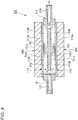
FIG. 3 is a vertical cross-sectional view of the structure of a cooling device according to an embodiment (taken along lines III-III inFIGs. 1 and2 ). -
FIG. 4 is vertical cross-sectional view of a modification example showing a modified structure of a cooling device according to an embodiment. -
FIG. 5 is vertical cross-sectional view of a modification example showing a modified structure of a cooling device according to an embodiment. - Embodiments of a cooling device according to the present invention will now be described in detail with reference to the accompanying drawings. It will be understood that the present invention is not limited to the following embodiment and may be modified in various ways within the scope of the present invention.
- With reference to
FIGs. 1 and3 , the structure of a cooling device according to an embodiment of the present invention will now be described. - As shown in
FIGs. 1 and2 , thecooling device 1 includes a cooling medium flow-passage forming member 11 having a substantially plate shape, made of aluminum. Thefirst member 2, thesecond member 3, thethird member 4, and thefourth member 5, which are electrical components to be cooled, are attachable to the cooling medium flow-passage forming member 11. - Herein, the
first member 2 and thethird member 4 are disposed on asurface 11a (upper surface; the upper surface inFIG. 1 ) of the cooling medium flow-passage forming member 11, next to each other along the longitudinal direction of the cooling medium flow-passage forming member 11, and thesecond member 3 and thefourth member 5 are disposed on theother surface 11b (lower surface; the lower surface inFIG. 1 ) of the cooling medium flow-passage forming member 11, next to each other along the longitudinal direction of the cooling medium flow-passage forming member 11. -
FIG. 1 is a schematic perspective view of thecooling device 1 as seen from above obliquely, andFIG. 2 is a schematic perspective view of thecooling device 1 as seen from below obliquely. InFIGs. 1 and2 , to show the structure of the cooling medium flow-passage forming member 11 and thefirst member 2 to thefourth member 5 clearly, thefirst member 2 to thefourth member 5 before attached to the cooling medium flow-passage forming member 11 are shown in solid lines, and thefirst member 2 to thefourth member 5 after attached to the cooling medium flow-passage forming member 11 are shown in double-dotted chain lines. - Furthermore, the first member and the second member in the claims of the present invention correspond to the
first member 2 and thesecond member 3, or thethird member 4 and thefourth member 5 in the present embodiment. - Furthermore, the first cooling space on the side of the first member in the claims of the present invention corresponds to the second cooling space S2 in the present embodiment, and the second cooling space on the side of the second member in the claims of the present invention corresponds to the third cooling space S3 in the present embodiment.
- As shown in
FIGs. 1 and2 , thefirst heatsink 12, thesecond heatsink 13, thethird heatsink 14, and thefourth heatsink 15 are mounted to thefirst member 2 to thefourth member 5, respectively, at the side attached to the cooling medium flow-passage forming member 11. Thefirst heatsink 12 to thefourth heatsink 15 include:bodies first member 2 to thefourth member 5; and a plurality ofcooling fins passage forming member 11 from thebodies 12a to 15a. - As shown in
FIGs. 1 to 3 , the cooling medium flow-passage forming member 11 has a throughhole 21 penetrating in an up-down direction (having openings on theupper surface 11a and thelower surface 11b) and disposed on the first side with respect to the longitudinal direction. The throughhole 21 has an area slightly smaller than thefirst heatsink 12 and thesecond heatsink 13, and the first member 2 (first heatsink 12) and the second member 3 (second heatsink 13) are attached from the up-down direction so as to close the throughhole 21. - Thus, a space (first cooling space) S1 is formed in the
cooling device 1, surrounded by the cooling medium flow-passage forming member 11 (through hole 21), the first member 2 (first heatsink 12), and the second member 3 (second heatsink 13). - In
FIG. 3 , thecooling fins 12b to 15b of thefirst heatsink 12 to thefourth heatsink 15 are simplified (shown by double-dotted chain line squares) for clarity. - Furthermore, as shown in
FIGs. 1 to 3 , the cooling medium flow-passage forming member 11 has anupper recess section 22 having an opening on theupper surface 11 a, disposed on the second side with respect to the longitudinal direction, and alower recess section 23 having an opening on thelower surface 11b, disposed on the second side with respect to the longitudinal direction. Theupper recess section 22 has an area slightly smaller than thethird heatsink 14, and the third member 4 (third heatsink 14) is attached from above so as to close theupper recess section 22. Furthermore, thelower recess section 23 has an area slightly smaller than thefourth heatsink 15, and the fourth member 5 (fourth heatsink 15) is attached from below so as to close thelower recess section 23. - Thus, a space (second cooling space) S2 and a space (third cooling space) S3 are formed in the
cooling device 1. The space S2 is surrounded by the cooling medium flow-passage forming member 11 (upper recess section 22) and thethird member 4. The space S3 is surrounded by the cooling medium flow-passage forming member 11 (lower recess section 23) and thefourth member 5. - Furthermore, as shown in
FIGs. 1 to 3 , the cooling medium flow-passage forming member 11 has: a coolingmedium supply port 31 that brings the outside and the first cooling space S1 into communication; a first coolingmedium communication port 32 that brings the first cooling space S1 and the second cooling space S2 into communication; a second coolingmedium communication port 33 that brings the second cooling space S2 and the third cooling space S3 into communication; and a coolingmedium discharge port 34 that brings the third cooling space S3 and the outside in to communication. - Thus, in the
cooling device 1, the cooling medium flow-passage forming member 11 and thefirst member 2 to the fourth member 5 (first heat sink 12 to fourth heatsink 15) form a cooling medium flow passage R (including the first cooling space S1 to the third cooling space S3) through which a cooling medium flows, and the cooling medium flowing through the cooling medium flow passage R cools thefirst heatsink 12 to thefourth heatsink 15, i.e., thefirst member 2 to thefourth member 5, which are disposed facing the cooling medium flow passage R. - Herein, as shown in
FIGs. 2 and3 , the lower recess section 23 (third cooling space S3) has aguide wall 41 for guiding (controlling) flow of the cooling medium. Theguide wall 41 is formed to have a substantially U shape which has an opening toward the first side in the longitudinal direction of the cooling medium flow-passage forming member 11, surrounding the second coolingmedium communication port 33, theguide walls 41 being erected on thebottom portion 23a (partition wall) of thelower recess section 23 and adjoining to thefourth heatsink 15. - Accordingly, while the cooling medium flows from the first side (left in
FIG. 3 ) of the cooling medium flow-passage forming member 11 with respect to the longitudinal direction to the second side (right inFIG. 3 ) with respect to the longitudinal direction in the first cooling space S1 and the second cooling space S2, the cooling medium flows from the second side with respect to the longitudinal direction to the first side with respect to the longitudinal direction on the inner side of the guide wall in the third cooling space, and then flows outward with respect to the width direction of theguide wall 41, and from the first side with respect to the longitudinal direction toward the second side with respect to the longitudinal direction on the outer side of theguide wall 41. - Furthermore, as shown in
FIGs. 1 to 3 , thecooling device 1 is provided with a first swirlgeneration enhancing member 51, a second swirlgeneration enhancing member 52, and a third swirlgeneration enhancing member 53 which generate swirls of the cooling medium in the first cooling space S1 to the third cooling space S3. The first swirlgeneration enhancing member 51 to the third swirlgeneration enhancing member 53 are rod-shaped members formed to extend in the width direction of the cooling medium flow-passage forming member 11 so as to cross the first cooling space S1 to the third cooling space S3, respectively. The first swirlgeneration enhancing member 51 to the third swirlgeneration enhancing member 53 havewall surfaces - Thus, in the first cooling space S1 to the third cooling space S3, when the cooling medium hits the first swirl
generation enhancing member 51 to the third swirl generation enhancing member 53 (wall surfaces 51a to 53a), the flow direction of the cooling medium is changed, and generation of swirls of the cooling medium is enhanced. - Swirls of the cooling medium cause the cooling medium around the
cooling fins 12b to 15b to circulate without being accumulated, so that cooling (heat dissipation) is efficiently performed for thefirst heatsink 12 to thefourth heatsink 15, i.e., thefirst member 2 to thefourth member 5. - Herein, as shown in
FIG. 3 , the first swirlgeneration enhancing member 51 is disposed substantially in the center of the cooling medium flow-passage forming member 11 with respect to the up-down direction, and spaces D1, D2 through each of which the cooling medium flows are disposed between the first swirlgeneration enhancing member 51 and thefirst heatsink 12, and between the first swirlgeneration enhancing member 51 and thesecond heatsink 13. Furthermore, the second swirlgeneration enhancing member 52 and the third swirlgeneration enhancing member 53 are erected on thebottom portion 22a (partition wall) of theupper recess section 22 and abottom portion 23a (partition wall) of thelower recess section 23, respectively, and spaces D3, D4 through each of which the cooling medium flows are disposed between the second swirlgeneration enhancing member 52 and thethird heatsink 14, and between the third swirlgeneration enhancing member 53 and thefourth heatsink 15. Thus, after hitting the first swirlgeneration enhancing member 51 to the third swirlgeneration enhancing member 53 and turning into swirls, the cooling medium passes through the respective spaces D1 to D4 and flows downstream. - Furthermore, the first swirl
generation enhancing member 51 has a crank-shaped cross section (taken in the direction shown inFIG. 3 ), and thewall surface 51a of the first swirlgeneration enhancing member 51 has a step. Herein, thewall surface 51a (first wall surface 51a1) formed adjacent to the first member 2 (upper side inFIG. 3 ) is disposed on the most upstream side of the first swirlgeneration enhancing member 51 with respect to the flow direction of the cooling medium, and thewall surface 51a (second wall surface 51a2) formed adjacent to the second member 3 (lower side inFIG. 3 ) is disposed downstream of thefirst wall surface 51a1 with respect to the flow direction of the cooling medium. - Thus, in the first cooling space S1, firstly, the cooling medium hits the
first wall surface 51a1 and thereby generation of swirls of the cooling medium is enhanced in the vicinity of the first heatsink 12 (coolingfin 12b), and then the cooling medium hits thesecond wall surface 51a2, and thereby generation of swirls of the cooling medium is enhanced in the vicinity of the second heatsink 13 (coolingfin 13b). - That is, in the first cooling space S1, generation of swirls is enhanced by the first swirl
generation enhancing member 51 at different positions and times, so that the first heatsink 12 (first member 2) is cooled prior to the second heatsink 13 (second member 3) by a slight difference. - With reference to
FIGs. 1 and3 , the effect of a cooling device according to an embodiment of the present invention will now be described. - First, the cooling medium is supplied to the first cooling space S1 via the cooling
medium supply port 31 from outside, and flows through the first cooling space S1 from the first side toward the second side with respect to the longitudinal direction of the cooling medium flow-passage forming member 11 (seeFIGs. 1 to 3 ). - Accordingly, in the first cooling space S1, the first swirl
generation enhancing member 51 enhances generation of swirls of the cooling medium. That is, the cooling medium hits thefirst wall surface 51a1 of the first swirlgeneration enhancing member 51, and thereby generation of swirls of the cooling medium is enhanced in the vicinity of the first heatsink 12 (cooling fin 12b), and then the cooling medium hits thesecond wall surface 51a2 of the first swirlgeneration enhancing member 11, and thereby generation of swirls of the cooling medium is enhanced in the vicinity of the second heatsink 13 (cooling fin 13b) (seeFIG. 3 ). Furthermore, after the first swirlgeneration enhancing member 51 enhances generation of swirls of the cooling medium, the cooling medium passes through the spaces D1, D2 to flow downstream (toward the second side with respect to the longitudinal direction of the cooling medium flow-passage forming member 11). - Next, the cooling medium is supplied to the second cooling space S2 via the cooling
medium communication port 32 from the first cooling space S1, and flows through the second cooling space S2 from the first side toward the second side with respect to the longitudinal direction of the cooling medium flow-passage forming member 11 (seeFIGs. 1 to 3 ). - Meanwhile, in the second cooling space S2, the second swirl
generation enhancing member 52 enhances generation of swirls of the cooling medium. That is, the cooling medium hits thesecond wall surface 52a of the second swirlgeneration enhancing member 52, and thereby generation of swirls of the cooling medium is enhanced in the vicinity of the third heatsink 14 (coolingfin 14b) (seeFIG. 3 ). Furthermore, after the second swirlgeneration enhancing member 52 enhances generation of swirls of the cooling medium, the cooling medium passes through the space D3 to flow downstream (toward the second side with respect to the longitudinal direction of the cooling medium flow-passage forming member 11). - Next, the cooling medium is supplied to the third cooling space S3 via the second cooling
medium communication port 33 from the second cooling space S2, and flows through the third cooling space S3 from the second side toward the first side with respect to the longitudinal direction of the cooling medium flow-passage forming member 11, at the inner side of theguide wall 41, then flows outward with respect to the width direction of theguide wall 41, and then flows from the first side toward the second side with respect to the longitudinal direction of the cooling medium flow-passage forming member 11 (seeFIGs. 1 to 3 ). - Meanwhile, in the third cooling space S3, the third swirl
generation enhancing member 53 enhances generation of swirls of the cooling medium, at the inner side and the outer side of theguide wall 41. That is, the cooling medium hits thewall surface 53a of the third swirlgeneration enhancing member 53, and thereby generation of swirls of the cooling medium is enhanced in the vicinity of the fourth heatsink 15 (coolingfin 15b) at the inner side and the outer side of the guide wall 41 (seeFIG. 3 ). Furthermore, after the third swirlgeneration enhancing member 53 enhances generation of swirls of the cooling medium, the cooling medium passes through the space D4 to flow downstream (toward the first side with respect to the longitudinal direction of the cooling medium flow-passage forming member 11 at the inner side of theguide wall 41, toward the second side with respect to the longitudinal direction of the cooling medium flow-passage forming member 11 at the outer side of the guide wall 41). - Next, the cooling medium is discharged outside from the third cooling space S3 via the cooling
medium discharge port 34. - As described above, in the
cooling device 1, firstly, the first member 2 (first heatsink 12) and the second member 3 (second heatsink 13) are cooled at the substantially same time, then the third member 4 (third heatsink 14) is cooled, and finally, the fourth member 5 (fourth heatsink 15) is cooled. - In the present embodiment, the
cooling device 1 and thefirst member 2 to thefourth member 5 are to be mounted to an electric vehicle, and thefirst member 2 to thefourth member 5 are preferably arranged in an order of priority of cooling. Herein, for the plurality of electrical components to be cooled, the order of priority of cooling is determined on the basis of the usage frequency and the amount of heat generation of the electrical components, for instance. - For instance, the
first member 2 may be a switching module for a driving motor, which houses an insulated gate bipolar transistor (IGBT) constituting a front motor control unit (FMCU), thesecond member 3 may be a switching module for a power generator housing an IGBT constituting a generator control unit (GCU), thethird member 4 may be a switching module for pressure increase housing an IGBT constituting a voltage control unit (VCU), and thefourth member 5 may include a coil for pressure increase behaving as a reactor. - Furthermore, in the present embodiment, as shown in
FIG. 3 , a partition wall 42 (member forming thebottom portion fin 14b) of thethird member 4 and the fourth heatsink 15 (coolingfin 15b) of thefourth member 5, thepartition wall 42 dividing the second cooling space S2 and the third cooling space S3, and the first coolingmedium communication port 32 and the second coolingmedium communication port 33 are provided, so that the cooling medium flows through the second cooling space S2 and then the third cooling space S3. In other words, thethird member 4 attached to the second cooling space S2 is cooled in priority to thefourth member 5 mounted to the third cooling space S3. - It will be understood that the present invention is not limited to this, and, for instance as shown in
FIG. 4 , apartition wall 142 may be provided between anupper heatsink 112 of an upper member (first member) 102 and alower heatsink 113 of a lower member (second member) 103, so as to divide the upper cooling space S102 and the lower cooling space S103, and a cooling medium supply port (cooling medium supply flow passage) 131 and a coolingmedium discharge port 134 that are in communication with both of the cooling spaces S102, S103 may be provided, so that the cooling medium flows through both of the cooling spaces S102, S103 at the substantially same time. - With this configuration, it is possible to suppress a large amount of cooling medium flowing through gaps (where the cooling
fins heatsinks heatsinks 112, 113 (members 102, 103) are cooled efficiently. - In the
cooling device 101 having the above configuration, swirlgeneration enhancing members partition wall 142, respectively, to enhance generation of swirls of the cooling medium in both of the upper and lower spaces of the partition wall 142 (upper cooling space S102 and lower cooling space S103), thus cooling both of theheatsinks 112, 113 (members 102, 103) even more efficiently. - Furthermore, in the present embodiment, as shown in
FIG. 3 , the cooling medium flow passage R through which the cooling medium flows is formed by thefirst heatsink 12 and thethird heatsink 14, thesecond heatsink 13 and thefourth heatsink 15, and the cooling medium flow-passage forming member 11 disposed between thefirst heatsink 12 to thefourth heatsink 15. - It will be understood that the present invention is not limited to this, and, for instance as shown in
FIG. 5 , the cooling medium flow passage R may be formed by anupper heatsink 212 disposed on an upper member (first member) 202 and alower heatsink 213 disposed on a lower member (second member) 203. - With this configuration, it is possible to exert a similar effect to that of an embodiment, while reducing the number of components of the
cooling device 201. - In the
cooling device 201 having the above configuration, swirlgeneration enhancing members heatsinks heatsinks 212, 213), thus cooling both of theheatsinks 212, 213 (members 202, 203) even more efficiently.
Claims (10)
- A cooling device for cooling a first member (2, 4) and a second member (3, 5), the cooling device comprising:a cooling medium flow passage (R) which is formed between the first member and the second member, and through which a cooling medium for cooling the first member and the second member flows; anda swirl generation enhancing portion (51, 52, 53) disposed in the cooling medium flow passage and configured to enhance generation of a swirl of the cooling medium flowing therein.
- The cooling device according to claim 1,
wherein the swirl generation enhancing portion (51, 52, 53) is a wall member having a wall surface (51a, 52a, 53a) extending in a direction which is perpendicular to a flow direction of the cooling medium. - The cooling device according to claim 1 or 2,
wherein the swirl generation enhancing portion is disposed so as to have a space (D1, D2, D3, D4), between itself and the first member and between itself and the second member. - The cooling device according to any one of claims 1 to 3,
wherein the swirl generation enhancing portion includes a first wall surface (51a1) formed on a side of the first member and a second wall surface (51a2) formed on a side of the second member, and
wherein the first wall surface is disposed upstream of the second wall surface in a flow direction of the cooling medium. - The cooling device according to any one of claims 1 to 4, comprising a partition wall (42) extending in a direction along a flow direction of the cooling medium and dividing a first cooling space (S2) on a side of the first member (4) and a second cooling space (S3) on a side of the second member (5).
- The cooling device according to claim 5, comprising a cooling medium supply flow passage (32, 33) for supplying the cooling medium to the first cooling space (S2) and the second cooling space (S3).
- The cooling device according to claim 5, comprising:a first cooling medium supply flow passage (32) for supplying the cooling medium to the first cooling space (S2); anda second cooling medium flow passage (33) for supplying the cooling medium to the second cooling space (S3) from the first cooling space.
- The cooling device according to any one of claims 1 to 7,
wherein the first member (2) comprises a first heatsink (12) having a cooling fin (12b) protruding toward the cooling medium flow passage formed thereon, and
wherein the second member (3) comprises a second heatsink (13) having a cooling fin (13b) protruding toward the cooling medium flow passage formed thereon. - The cooling device according to claim 8,
wherein the cooling medium flow passage (R) is formed by the first heatsink (12), the second heatsink (13), and a housing (11) disposed between the first heatsink and the second heatsink. - The cooling device according to claim 8,
wherein the cooling medium flow passage (R) is formed by the first heatsink (12) and the second heatsink (13).
Applications Claiming Priority (1)
| Application Number | Priority Date | Filing Date | Title |
|---|---|---|---|
| JP2016254595A JP2018107361A (en) | 2016-12-28 | 2016-12-28 | Cooling system |
Publications (1)
| Publication Number | Publication Date |
|---|---|
| EP3343606A1 true EP3343606A1 (en) | 2018-07-04 |
Family
ID=60953601
Family Applications (1)
| Application Number | Title | Priority Date | Filing Date |
|---|---|---|---|
| EP17210421.8A Withdrawn EP3343606A1 (en) | 2016-12-28 | 2017-12-22 | Cooling device |
Country Status (4)
| Country | Link |
|---|---|
| US (1) | US20180184543A1 (en) |
| EP (1) | EP3343606A1 (en) |
| JP (1) | JP2018107361A (en) |
| CN (1) | CN108257930A (en) |
Families Citing this family (15)
| Publication number | Priority date | Publication date | Assignee | Title |
|---|---|---|---|---|
| US10850623B2 (en) | 2017-10-30 | 2020-12-01 | Sf Motors, Inc. | Stacked electric vehicle inverter cells |
| US10790758B2 (en) | 2018-03-08 | 2020-09-29 | Chongqing Jinkang New Energy Vehicle Co., Ltd. | Power converter for electric vehicle drive systems |
| US10756649B2 (en) | 2018-03-23 | 2020-08-25 | Chongqing Jinkang New Energy Vehicle Co., Ltd. | Inverter module having multiple half-bridge modules for a power converter of an electric vehicle |
| US10779445B2 (en) | 2018-03-23 | 2020-09-15 | Chongqing Jinkang New Energy Vehicle Co., Ltd. | Inverter module having multiple half-bridge modules for a power converter of an electric vehicle |
| US10594230B2 (en) | 2018-03-23 | 2020-03-17 | Sf Motors, Inc. | Inverter module having multiple half-bridge modules for a power converter of an electric vehicle |
| US10772242B2 (en) | 2018-04-17 | 2020-09-08 | Chongqing Jinkang New Energy Vehicle Co., Ltd. | Inverter module of an electric vehicle |
| US10778117B2 (en) | 2018-04-17 | 2020-09-15 | Chongqing Jinkang New Energy Vehicle Co., Ltd. | Inverter module of an electric vehicle |
| US10600578B2 (en) | 2018-04-26 | 2020-03-24 | Sf Motors, Inc. | Electric vehicle inverter module capacitors |
| US10660242B2 (en) | 2018-04-26 | 2020-05-19 | Chongqing Jinkang New Energy Vehicle Co., Ltd. | Electric vehicle inverter module heat sink |
| US10608423B2 (en) | 2018-04-26 | 2020-03-31 | Sf Motors, Inc. | Electric vehicle inverter module laminated bus bar |
| US10600577B2 (en) | 2018-04-26 | 2020-03-24 | Sf Motors, Inc. | Electric vehicle inverter module capacitors |
| TWM607522U (en) * | 2020-04-12 | 2021-02-11 | 湛積股份有限公司 | Heat dissipating module and motor controller thereof |
| JP7487550B2 (en) * | 2020-05-13 | 2024-05-21 | マツダ株式会社 | Cooling structure for mobile computing device |
| JP7184138B1 (en) * | 2021-10-01 | 2022-12-06 | 富士電機株式会社 | power converter |
| DE102023113542A1 (en) * | 2023-05-24 | 2024-11-28 | Erwin Quarder Systemtechnik Gmbh | cooling component for dissipating heat |
Citations (6)
| Publication number | Priority date | Publication date | Assignee | Title |
|---|---|---|---|---|
| US20040184237A1 (en) * | 2003-03-05 | 2004-09-23 | Shyy-Woei Chang | Heat dissipation device with liquid coolant |
| EP1925898A1 (en) * | 2005-09-13 | 2008-05-28 | Mitsubishi Denki Kabushiki Kaisha | Heat sink |
| US20090250195A1 (en) * | 2006-06-14 | 2009-10-08 | Toyota Jidosha Kabushiki Kaisha | Heat sink and cooler |
| US20100090336A1 (en) * | 2007-01-11 | 2010-04-15 | Toyota Jidosha Kabushiki Kaisha | Semiconductor element cooling structure |
| WO2012029165A1 (en) | 2010-09-02 | 2012-03-08 | トヨタ自動車株式会社 | Semiconductor module |
| DE102015209274A1 (en) * | 2015-05-21 | 2016-11-24 | Robert Bosch Gmbh | Heat exchanger, cooling system |
Family Cites Families (5)
| Publication number | Priority date | Publication date | Assignee | Title |
|---|---|---|---|---|
| JP2007250753A (en) * | 2006-03-15 | 2007-09-27 | Mitsubishi Electric Corp | Cold plate |
| JP2011066199A (en) * | 2009-09-17 | 2011-03-31 | Toyota Motor Corp | Power controller |
| JP2011096765A (en) * | 2009-10-28 | 2011-05-12 | Toyota Motor Corp | Cooling apparatus for semiconductor device |
| JP4920071B2 (en) * | 2009-11-12 | 2012-04-18 | 株式会社日本自動車部品総合研究所 | Semiconductor device cooling device |
| JP5523542B1 (en) * | 2012-12-07 | 2014-06-18 | 三菱電機株式会社 | Cooling system |
-
2016
- 2016-12-28 JP JP2016254595A patent/JP2018107361A/en active Pending
-
2017
- 2017-12-15 US US15/843,688 patent/US20180184543A1/en not_active Abandoned
- 2017-12-22 EP EP17210421.8A patent/EP3343606A1/en not_active Withdrawn
- 2017-12-26 CN CN201711435390.5A patent/CN108257930A/en active Pending
Patent Citations (6)
| Publication number | Priority date | Publication date | Assignee | Title |
|---|---|---|---|---|
| US20040184237A1 (en) * | 2003-03-05 | 2004-09-23 | Shyy-Woei Chang | Heat dissipation device with liquid coolant |
| EP1925898A1 (en) * | 2005-09-13 | 2008-05-28 | Mitsubishi Denki Kabushiki Kaisha | Heat sink |
| US20090250195A1 (en) * | 2006-06-14 | 2009-10-08 | Toyota Jidosha Kabushiki Kaisha | Heat sink and cooler |
| US20100090336A1 (en) * | 2007-01-11 | 2010-04-15 | Toyota Jidosha Kabushiki Kaisha | Semiconductor element cooling structure |
| WO2012029165A1 (en) | 2010-09-02 | 2012-03-08 | トヨタ自動車株式会社 | Semiconductor module |
| DE102015209274A1 (en) * | 2015-05-21 | 2016-11-24 | Robert Bosch Gmbh | Heat exchanger, cooling system |
Also Published As
| Publication number | Publication date |
|---|---|
| JP2018107361A (en) | 2018-07-05 |
| US20180184543A1 (en) | 2018-06-28 |
| CN108257930A (en) | 2018-07-06 |
Similar Documents
| Publication | Publication Date | Title |
|---|---|---|
| US20180184543A1 (en) | Cooling device | |
| JP6482954B2 (en) | Liquid cooling system | |
| US9245821B2 (en) | Cooling device for semiconductor module, and semiconductor module | |
| US8291967B2 (en) | Heat sink and cooler | |
| US9320158B2 (en) | Vehicle control device | |
| KR20150025755A (en) | Apparatus for cooling inverter | |
| JP6482955B2 (en) | Liquid cooling system | |
| CN103812356B (en) | The cooling structure of inverter | |
| JP6324457B2 (en) | Electrical equipment | |
| KR102392458B1 (en) | Cover having cooling protrusion for battery cell of eco-friendly vehicle | |
| JP2016219572A (en) | Liquid cooling cooler | |
| JP2016219571A (en) | Liquid cooling cooler | |
| KR102392459B1 (en) | Cover having cooling hole for battery cell of eco-friendly vehicle | |
| KR102034649B1 (en) | Air cooling system | |
| EP3782835B1 (en) | Vehicle battery pack | |
| JP7644236B2 (en) | Power Semiconductor Components | |
| JP6837565B2 (en) | Railroad vehicle power converters and railroad vehicles equipped with power converters | |
| JP2017216293A (en) | Fluid-cooling type cooling device | |
| JP5471891B2 (en) | Power converter | |
| JP6932632B2 (en) | Liquid cooling system | |
| JP6632879B2 (en) | Liquid cooling system | |
| JP4797954B2 (en) | Cooling structure of radiating fin | |
| JP2014066250A (en) | Structure of cooling water tank | |
| WO2018229902A1 (en) | Casing, electronic machine, and cooling method | |
| JP2017195226A (en) | Liquid cooling system |
Legal Events
| Date | Code | Title | Description |
|---|---|---|---|
| PUAI | Public reference made under article 153(3) epc to a published international application that has entered the european phase |
Free format text: ORIGINAL CODE: 0009012 |
|
| 17P | Request for examination filed |
Effective date: 20171222 |
|
| AK | Designated contracting states |
Kind code of ref document: A1 Designated state(s): AL AT BE BG CH CY CZ DE DK EE ES FI FR GB GR HR HU IE IS IT LI LT LU LV MC MK MT NL NO PL PT RO RS SE SI SK SM TR |
|
| AX | Request for extension of the european patent |
Extension state: BA ME |
|
| RBV | Designated contracting states (corrected) |
Designated state(s): AL AT BE BG CH CY CZ DE DK EE ES FI FR GB GR HR HU IE IS IT LI LT LU LV MC MK MT NL NO PL PT RO RS SE SI SK SM TR |
|
| 17Q | First examination report despatched |
Effective date: 20190226 |
|
| RAP1 | Party data changed (applicant data changed or rights of an application transferred) |
Owner name: MITSUBISHI JIDOSHA ENGINEERING KABUSHIKI KAISHA Owner name: MITSUBISHI JIDOSHA KOGYO KABUSHIKI KAISHA |
|
| STAA | Information on the status of an ep patent application or granted ep patent |
Free format text: STATUS: THE APPLICATION IS DEEMED TO BE WITHDRAWN |
|
| 18D | Application deemed to be withdrawn |
Effective date: 20200701 |