EP3343584B1 - Non-contact switch devices for use on material handling equipment - Google Patents
Non-contact switch devices for use on material handling equipment Download PDFInfo
- Publication number
- EP3343584B1 EP3343584B1 EP17156115.2A EP17156115A EP3343584B1 EP 3343584 B1 EP3343584 B1 EP 3343584B1 EP 17156115 A EP17156115 A EP 17156115A EP 3343584 B1 EP3343584 B1 EP 3343584B1
- Authority
- EP
- European Patent Office
- Prior art keywords
- magnet
- contact switch
- switch
- reed
- switch device
- Prior art date
- Legal status (The legal status is an assumption and is not a legal conclusion. Google has not performed a legal analysis and makes no representation as to the accuracy of the status listed.)
- Active
Links
Images



Classifications
-
- H—ELECTRICITY
- H01—ELECTRIC ELEMENTS
- H01H—ELECTRIC SWITCHES; RELAYS; SELECTORS; EMERGENCY PROTECTIVE DEVICES
- H01H36/00—Switches actuated by change of magnetic field or of electric field, e.g. by change of relative position of magnet and switch, by shielding
- H01H36/0006—Permanent magnet actuating reed switches
- H01H36/0013—Permanent magnet actuating reed switches characterised by the co-operation between reed switch and permanent magnet; Magnetic circuits
-
- H—ELECTRICITY
- H01—ELECTRIC ELEMENTS
- H01H—ELECTRIC SWITCHES; RELAYS; SELECTORS; EMERGENCY PROTECTIVE DEVICES
- H01H36/00—Switches actuated by change of magnetic field or of electric field, e.g. by change of relative position of magnet and switch, by shielding
- H01H36/0006—Permanent magnet actuating reed switches
- H01H36/0046—Limit switches, also fail-safe operation or anti-tamper considerations
-
- B—PERFORMING OPERATIONS; TRANSPORTING
- B62—LAND VEHICLES FOR TRAVELLING OTHERWISE THAN ON RAILS
- B62B—HAND-PROPELLED VEHICLES, e.g. HAND CARTS OR PERAMBULATORS; SLEDGES
- B62B3/00—Hand carts having more than one axis carrying transport wheels; Steering devices therefor; Equipment therefor
- B62B3/04—Hand carts having more than one axis carrying transport wheels; Steering devices therefor; Equipment therefor involving means for grappling or securing in place objects to be carried; Loading or unloading equipment
- B62B3/06—Hand carts having more than one axis carrying transport wheels; Steering devices therefor; Equipment therefor involving means for grappling or securing in place objects to be carried; Loading or unloading equipment for simply clearing the load from the ground
- B62B3/0618—Hand carts having more than one axis carrying transport wheels; Steering devices therefor; Equipment therefor involving means for grappling or securing in place objects to be carried; Loading or unloading equipment for simply clearing the load from the ground using fluid lifting mechanisms
-
- B—PERFORMING OPERATIONS; TRANSPORTING
- B62—LAND VEHICLES FOR TRAVELLING OTHERWISE THAN ON RAILS
- B62D—MOTOR VEHICLES; TRAILERS
- B62D51/00—Motor vehicles characterised by the driver not being seated
- B62D51/001—Motor vehicles characterised by the driver not being seated characterised by the vehicle control device
- B62D51/002—Motor vehicles characterised by the driver not being seated characterised by the vehicle control device comprising safety arrangements
-
- H—ELECTRICITY
- H01—ELECTRIC ELEMENTS
- H01H—ELECTRIC SWITCHES; RELAYS; SELECTORS; EMERGENCY PROTECTIVE DEVICES
- H01H36/00—Switches actuated by change of magnetic field or of electric field, e.g. by change of relative position of magnet and switch, by shielding
- H01H36/0006—Permanent magnet actuating reed switches
-
- H—ELECTRICITY
- H01—ELECTRIC ELEMENTS
- H01H—ELECTRIC SWITCHES; RELAYS; SELECTORS; EMERGENCY PROTECTIVE DEVICES
- H01H36/00—Switches actuated by change of magnetic field or of electric field, e.g. by change of relative position of magnet and switch, by shielding
- H01H36/0006—Permanent magnet actuating reed switches
- H01H36/0013—Permanent magnet actuating reed switches characterised by the co-operation between reed switch and permanent magnet; Magnetic circuits
- H01H36/002—Actuation by moving ferromagnetic material, switch and magnet being fixed
-
- H—ELECTRICITY
- H01—ELECTRIC ELEMENTS
- H01H—ELECTRIC SWITCHES; RELAYS; SELECTORS; EMERGENCY PROTECTIVE DEVICES
- H01H36/00—Switches actuated by change of magnetic field or of electric field, e.g. by change of relative position of magnet and switch, by shielding
- H01H36/0006—Permanent magnet actuating reed switches
- H01H36/0066—Permanent magnet actuating reed switches magnet being removable, e.g. part of key pencil
-
- H—ELECTRICITY
- H01—ELECTRIC ELEMENTS
- H01H—ELECTRIC SWITCHES; RELAYS; SELECTORS; EMERGENCY PROTECTIVE DEVICES
- H01H36/00—Switches actuated by change of magnetic field or of electric field, e.g. by change of relative position of magnet and switch, by shielding
- H01H36/02—Switches actuated by change of magnetic field or of electric field, e.g. by change of relative position of magnet and switch, by shielding actuated by movement of a float carrying a magnet
-
- H—ELECTRICITY
- H01—ELECTRIC ELEMENTS
- H01H—ELECTRIC SWITCHES; RELAYS; SELECTORS; EMERGENCY PROTECTIVE DEVICES
- H01H2223/00—Casings
- H01H2223/002—Casings sealed
Definitions
- the invention relates to a pallet truck using a non-contact switch device, wherein the non-contact switch device realizes switch on and off positions by the presence or absence of magnetic induction between a magnet and a reed switch.
- switch actuation to move from the off to the on position may occur based on the presence or absence of a magnet and/or shielding or non-shielding of a magnet relative to a reed switch.
- Material handling equipment is widely used in warehouses, stores and other facilities, and electric powered vehicles are continuing to become more popular for at least environmental and noise related advantages over gas powered vehicles. Electric powered vehicles also have advantages over manual powered vehicles relating to at least capacity, operator safety and efficiency. Electrical switches are commonly used on material handling equipment to realize different functions, such as a main key switch device having power on and off positions relating to providing power to the material handling equipment, an interlock switch device having on and off positions relating to being able to drive the material handling equipment, and a limit switch device having on and off positions relating to controlling movement of a load lift portion of material handling equipment.
- Switches used in material handling equipment generally are of a type of electro-mechanical switch or mechanical micro switch. Such switches provide a particular function by having the operator directly move an electrical contact to touch or engage another electrical contact in a specific position, such as when turning a key in a switch lock cylinder.
- the switches may require a fairly large volume, and tend to make switch design and layout somewhat difficult.
- the common switches used also have a relatively short service life because the contacts may be exposed to the atmosphere and their ability to function is subject to wear, corrosion and dirty working conditions. These issues can lead to increased costs due to downtime of the equipment and the need for maintenance or replacement.
- US 3 896 892 A relates to improvements in a manual control for a self-propelled vehicle which allows the vehicle to be driven and steered by an operator on foot.
- the improved vehicle includes control means composed of a plurality of reed switches.
- JP H07 61790 A relates to a control apparatus for a forklift truck, the control system of this control apparatus including a reed switch.
- JP 2002 178738 A provides a rear wheel suspension device of a reach forklift in which a plurality of memory-type reed switches are disposed.
- JP S63 29850 U relates to a forklift truck with interlock switch functionality.
- EP 1 285 568 A1 relates to electric lawn mowers including a non-contact reed switch.
- US 3 009 033 A relates to a limit switch operated without physical contact with the actuating member.
- US 2015/045948 A1 relates to a robotic lawnmower having a deactivated state, a stand by state and an activated state.
- US 2005/016779 A1 relates to a pallet truck having a tiller arm.
- the non-contact switch devices of the present disclosure include reed switch configurations that include switch elements in the form of a pair of contacts on ferrous metal reeds that are encapsulated within inert gas or a vacuum as they are hermetically sealed in a glass tube or chamber. As such, the reeds and contacts are not subject to the atmosphere, or the heavy wear, corrosion or dirty working conditions of the traditional switches.
- the sealed structure provides greater safety because they permit use of the non-contact switch devices in a corrosive atmosphere or in the presence of flammable or explosive gas.
- the non-contact switch devices also are relatively compact, reliable and provide for easy design and layout, with simple actuation.
- the switches also can be designed with the reed contacts normally in an open position, so as to close when subjected to a magnetic field, or normally closed, so as to open when subjected to a magnetic field, with the reed contacts returning to their normal position when the magnet is removed or shielded from the reed switch.
- a pallet truck according to claim 1 is provided.
- FIGS. 1A-5C Examples of non-contact switch devices that realize switch on and off positions by the presence or absence of magnetic induction between a magnet and a reed switch are shown in various forms in FIGS. 1A-5C for use on material handling equipment, such as a pallet truck.
- the non-contact switch devices are shown for example in the form of a main power switch 1 for a pallet truck in FIGS. 1A-1C , with a schematic view of the reed switch elements of that non-contact switch device in FIGS. 2A-2B , in the form of an interlock switch 20 on a handle of a pallet truck in FIGS.
- FIGS. 4A-4B with a schematic view of the reed switch elements of that non-contact switch device in FIGS. 4A-4B , and in the form of a limit switch 40 associated with movement of the load lift portion of the pallet truck in FIGS. 5 and 5A-5B , which also is represented by the schematic view of the reed switch elements of that non-contact switch device in FIGS. 4A-4B .
- the non-contact switch devices 1, 20 and 40 of the present disclosure are embodied in reed switch configurations that include reed switch elements in the form of a pair of contacts on the ends of reeds that are within a hermetically sealed glass envelope or chamber. At least one of the reeds is constructed using ferromagnetic material, such as a ferrous metal, for example iron, cobalt and nickel, while depending on the design, the other reed may be constructed using non-magnetic material.
- the reed switch elements may be predisposed to normally be open or spaced apart when not in the presence of a magnet, so as to close or touch together in the presence of a magnet, such as in the non-contact switch device 1 represented in FIGS.
- the reed switch elements may be predisposed to normally be closed or touching together when not in the presence of a magnet, so as to open or move to be spaced apart in the presence of a magnet, such as in the non-contact switch devices 20 and 40 represented in FIGS. 3 and 3A-3C , 4A-4B , 5 and 5A-5C .
- the reed switch may be designed to have one or both reeds move when subjected to a magnetic force.
- the disclosure provides a first example non-contact switch 1 that is a main power switch, which includes a magnet 2 and a reed switch 3.
- the reed switch 3 is held within and connected to a switch body 4 that includes a switch socket 5 and may be mounted on a surface of material handling equipment for convenient acccss by an operator, such as on a top surface of a pallet truck or the like.
- the magnet 2 may be a permanent magnet and is held or embedded within a magnet cap 6, which simply otherwise may be constructed of plastic and which is removably receivable in the switch socket 5.
- the reed switch 3 includes reed elements 7 and 8 that are encapsulated within inert gas or a vacuum as they are hermetically sealed in a glass tube or chamber 9.
- the non-contact switch device 1 is normally in an open position because the reed elements 7 and 8 are normally in a spaced apart position when not in the presence of the magnet 2.
- the magnet cap 6 is placed in the switch socket 5, the magnet 2 is brought into close proximity of the reed switch 3.
- the magnetic field caused by the presence of the magnet 2 causes the reed element 7 to be attracted to and move toward the magnet 2, which results in the reed element 7 moving into contact with the reed element 8, closing the reed switch 3 and thereby moving the non-contact switch device 1 to an on position.
- the non-contact switch device 1 including the magnet 2 and magnetic reed switch 3 preferably provides an easier structure to employ, requires a smaller volume, is actuated at a faster speed, and yields a longer service life than traditional mechanical switches used on material handling equipment.
- the non-contact switch device 1 also has stronger resistance and is more reliable than electric switches. Its switching reed elements 7 and 8 are sealed in an inert gas or vacuum, and are not in contact with the external environment. This greatly reduces the co-oxidation and carbonization by contacts during the opening and closing proccss. It also prevents external vapor, dust and other impurities from eroding the contacts.
- FIGS. 1A-1C and 2A-2B a first example non-contact switch device 1 is represented in FIGS. 1A-1C and 2A-2B.
- the non-contact switch device 1 for use on material handling equipment includes a magnet 2 and a reed switch 3, wherein the non-contact switch device 1 has on and off positions achieved by the presence or absence of magnetic induction between the magnet 2 and the reed switch 3.
- the non-contact switch device 1 is in the on position when the magnet 2 is placed in close proximity to the reed switch 3, and is in the off position when the magnet 2 is not in close proximity to the reed switch 3.
- the example non-contact switch device 1 has the magnet cap 6 that includes the magnet 2 and the switch socket 5 that includes the reed switch 3.
- the magnet cap 6 When the magnet cap 6 is placed in the switch socket 5, the magnet 2 is in close proximity to the reed switch 3 and the non-contact switch device 1 is in the on position.
- the magnet cap 6 When the magnet cap 6 is removed from the switch socket 5, the magnet 2 is not in close proximity to the reed switch 3 and the non-contact switch device 1 is in the off position.
- the magnet cap 6 and switch socket 5 are part of a main power switch device for material handling equipment, such as a pallet truck, with the main power switch having a power on and off function corresponding to the on and off positions, wherein the magnet cap 6 may simply be removed and placed in a pocket when the equipment is not in use.
- the disclosure provides a second example non-contact switch 20 wherein a magnet 22 and a reed switch 23 are in a spaced apart position and the non-contact switch device 20 is in the off position when a shielding member 21 is located between the magnet 22 and the reed switch 23, and is in the on position when the shielding member 21 is not located between the magnet 22 and the reed switch 23.
- the second example non-contact switch device 20 is in the form of an interlock switch.
- the magnet 22 and reed switch 23 may be connected to the same component, such as a bracket, and are connected to a base portion 24 of a pallet truck P and are spaced apart by a gap 25.
- the magnet 22 may be a permanent magnet.
- the shielding member 21 is connected to an operator handle 26 that pivots relative to the base portion 24, and the shielding member 21 has more than one extensions that act as a shield.
- the magnet 22 and the reed switch 23 are spaced apart by the gap 25 and the non-contact switch device 20 is in the off position when the shielding member 21 is located between the magnet 22 and the reed switch 23, and is in the on position when the shielding member 21 is not located between the magnet 22 and the reed switch 23.
- the reed switch 23 includes reed elements 27 and 28 that are encapsulated within inert gas or a vacuum as they are hermetically sealed in a glass tube or chamber 29.
- the non-contact switch device 20 which has the magnet 22 and reed switch 23 in fixed positions with the gap 25 therebetween, normally is in a closed position because the magnet 22 attracts the reed element 27 toward and into contact with the reed elements 28.
- the shielding element 21 is moved to be located in the gap 25 between the magnet 22 and the reed switch 23, as seen in FIG. 4A , the reed element 27 returns to a pre-deflected position spaced apart from reed element 28, opening the reed switch 23, so as to be moved to the off position.
- FIG. 3 is a side view of the pallet truck P showing the operator handle 26 in three example positions A, B and C, which provide different operational states of the non-contact switch device 20 in the form of an interlock switch.
- the example pallet truck P is shown with the operator handle in a generally vertical parked position A, an angled operating position B, and a generally horizontal inactive position C.
- a close up view of the non-contact switch device 20 in FIG. 3A corresponds to the generally parked position A of the operator handle 26.
- the shielding member 21 is located between the magnet 22 and the reed switch 23, placing the non-contact switch device 20 in an open position, as shown in FIG. 4A .
- the reed elements 27 and 28 no longer in contact, the power cannot flow through the reed switch 23 and a controller prevents the pallet truck P from being driven.
- the operator may grasp the operator handle 26 and tilt it to an inclined operating position, such as position B.
- the operating position generally may be at an angular position anywhere between the generally vertical or fully upright position A and the generally horizontal or fully lowered position C.
- the shielding member 21 that is connected to the operator handle 26 is moved so as to no longer be located in the gap 25 between the magnet 22 and the reed switch 23, as represented in FIGS. 3B and 4B .
- the operator is able to utilize the controls on the operator handle 26 to operate and drive the pallet truck P.
- the disclosure provides a third example non-contact switch 40 wherein a magnet 42 and a reed switch 43 are in a spaced apart position and the non-contact switch device 40 is in the off position when a shielding member 41 is located between the magnet 42 and the reed switch 43, and is in the on position when the shielding member 41 is not located between the magnet 42 and the reed switch 43.
- the third example non-contact switch device 40 is in the form of a limit switch.
- the magnet 42 and reed switch 43 may be connected to the same component, such as a bracket, and are connected to a load lift portion 44 of a pallet truck P and are spaced apart by a gap 45.
- the magnet 42 may be a permanent magnet.
- the shielding member 41 is connected to a rotating link 46 that pivots relative to the load lift portion 44 as the load lift portion 44 is raised or lowered.
- the magnet 42 and the reed switch 43 are spaced apart by the gap 45 and the non-contact switch device 40 is in the on position when the shielding member 41 is not located between the magnet 42 and the reed switch 43, and is in the off position when the shielding member 41 is located between the magnet 42 and the reed switch 43.
- the reed switch 43 of the third example includes reed elements 27 and 28 that are encapsulated within inert gas or a vacuum as they are hermetically sealed in a glass tube or chamber 29.
- FIG. 5 shows a lowered position A of the load lift portion 44, which corresponds to the position shown in FIG. 5A .
- the load lift portion 44 may be raised to a preselected position, such as the position B shown in FIG. 5 .
- FIG. 5 corresponds to the position of the non-contact switch device 40 shown in FIGS. 5B and 5C , where the link 46 has rotated sufficiently to cause the shielding member 41 to move to a location in the gap 45 between the magnet 42 and the reed switch 43.
- This further corresponds to the schematic view seen in FIG. 4A where the non-contact switch device 40 is in the off position, which stops the rising load lift portion 44 at a preselected uppermost raised position, which represents a limit of travel.
- the magnet 42 and reed switch 43 are in fixed positions with the gap 45 therebetween, and when the load lift portion 44 is in the lowered position, the non-contact switch device 40 normally is in a closed position because the magnet 42 attracts the reed element 27 toward and into contact with the reed elements 28, as shown in FIG. 4B .
- the link 46 rotates as the load lift portion 44 is raised, the shielding element 41 is moved to be located in the gap 45 between the magnet 42 and the reed switch 43, as seen in FIG. 4A , where the reed element 27 returns to a pre-deflected position spaced apart from reed element 28, opening the reed switch 43, so as to be moved to the off position.
- this third example non-contact switch device 40 includes a shielding member 41, it will be appreciated that the non-contact switch device 40 also operates in response to the presence or absence of a magnetic field between the magnet 42 and the reed switch 43.
- the reed switch and magnet of the non-contact switch device of the invention may be in a spaced apart position, wherein it is possible for the non-contact switch device to be in the off position when a shielding member is located between the magnet and the reed switch, and to be in the on position when the shielding member is not located between the magnet and the reed switch.
- the non-contact switch device may be part of a pallet truck having an operator handle and may be in the off position with the shielding member located between the magnet and the reed switch when the operator handle is in a generally vertical position, wherein it also may be so that the pallet truck is in a parked position when the operator handle is in the generally vertical position.
- the non-contact switch device may be part of a pallet truck having an operator handle and may be in the on position with the shielding member not located between the magnet and the reed switch when the operator handle is in a generally inclined operating position, wherein it also may be so that when the operator handle is in the generally inclined operating position, the pallet truck is drivable. Still further, the non-contact switch device may be part of a pallet truck having an operator handle and may be in the off position with the shielding member located between the magnet and the reed switch when the operator handle is in a generally horizontal position, wherein it also may be so that the operator handle is in an inactive position when the operator handle has been moved to the generally horizontal position.
- the non-contact switch devices provide advantageous features by permitting more compact, reliable switches that are less susceptible to wear, corrosion and issues that shorten switch service life. This results in lower costs and less downtime for maintenance or switch replacement.
Landscapes
- Engineering & Computer Science (AREA)
- Chemical & Material Sciences (AREA)
- Combustion & Propulsion (AREA)
- Transportation (AREA)
- Mechanical Engineering (AREA)
- Switches That Are Operated By Magnetic Or Electric Fields (AREA)
Description
- The invention relates to a pallet truck using a non-contact switch device, wherein the non-contact switch device realizes switch on and off positions by the presence or absence of magnetic induction between a magnet and a reed switch. Depending on the structure of the non-contact switch device, switch actuation to move from the off to the on position may occur based on the presence or absence of a magnet and/or shielding or non-shielding of a magnet relative to a reed switch.
- Material handling equipment is widely used in warehouses, stores and other facilities, and electric powered vehicles are continuing to become more popular for at least environmental and noise related advantages over gas powered vehicles. Electric powered vehicles also have advantages over manual powered vehicles relating to at least capacity, operator safety and efficiency. Electrical switches are commonly used on material handling equipment to realize different functions, such as a main key switch device having power on and off positions relating to providing power to the material handling equipment, an interlock switch device having on and off positions relating to being able to drive the material handling equipment, and a limit switch device having on and off positions relating to controlling movement of a load lift portion of material handling equipment.
- Traditional contact switches used in material handling equipment generally are of a type of electro-mechanical switch or mechanical micro switch. Such switches provide a particular function by having the operator directly move an electrical contact to touch or engage another electrical contact in a specific position, such as when turning a key in a switch lock cylinder. The switches may require a fairly large volume, and tend to make switch design and layout somewhat difficult. The common switches used also have a relatively short service life because the contacts may be exposed to the atmosphere and their ability to function is subject to wear, corrosion and dirty working conditions. These issues can lead to increased costs due to downtime of the equipment and the need for maintenance or replacement.
-
US 3 896 892 A relates to improvements in a manual control for a self-propelled vehicle which allows the vehicle to be driven and steered by an operator on foot. The improved vehicle includes control means composed of a plurality of reed switches. -
JP H07 61790 A -
JP 2002 178738 A -
JP S63 29850 U -
EP 1 285 568 A1 -
US 3 009 033 A relates to a limit switch operated without physical contact with the actuating member. -
US 2015/045948 A1 relates to a robotic lawnmower having a deactivated state, a stand by state and an activated state. -
US 2005/016779 A1 relates to a pallet truck having a tiller arm. - The subject matter of this disclosure provides advantages over the typical electrical switches normally used on prior art electrical material handling equipment, such as pallet trucks, pallet stackers and the like. The non-contact switch devices of the present disclosure include reed switch configurations that include switch elements in the form of a pair of contacts on ferrous metal reeds that are encapsulated within inert gas or a vacuum as they are hermetically sealed in a glass tube or chamber. As such, the reeds and contacts are not subject to the atmosphere, or the heavy wear, corrosion or dirty working conditions of the traditional switches. The sealed structure provides greater safety because they permit use of the non-contact switch devices in a corrosive atmosphere or in the presence of flammable or explosive gas.
- The non-contact switch devices also are relatively compact, reliable and provide for easy design and layout, with simple actuation. The switches also can be designed with the reed contacts normally in an open position, so as to close when subjected to a magnetic field, or normally closed, so as to open when subjected to a magnetic field, with the reed contacts returning to their normal position when the magnet is removed or shielded from the reed switch.
- This non-contact actuation based on the presence or absence of a magnetic field is in contrast to prior art electric switches used on material handling equipment that have switch contacts that require touching or engagement between contacts that also may be exposed to the atmosphere and suffer due to wear, corrosion and dirty conditions, leading to a short service life.
- According to the present invention a pallet truck according to
claim 1 is provided. - It is to be understood that both the foregoing general description and the following detailed description are exemplary and provided for purposes of explanation only, and are not restrictive with respect to the claimed subject matter. Further features and advantages will become more fully apparent in the following description of the example preferred embodiment and from the appended claims.
- In describing the preferred examples, references are made to the accompanying drawing figures wherein like parts have like reference numerals. For ease of viewing and comprehension, the figures show only particular operative components of the electrical systems.
-
FIG. 1A shows a top view of a non-contact switch device functioning as a main power switch for material handling equipment, with a magnet cap having a magnet and being inserted into a switch socket of a switch body. -
FIG. 1B is a side view of the switch body ofFIG 1A , with a partial cutaway in the area of the inserted magnet cap and the switch socket. -
FIG. 1C is a bottom view of the switch body ofFIG. 1A , showing components of the switch socket. -
FIG. 2A is a schematic view corresponding to an open position of the non-contact switch device ofFIGS. 1A-1C , showing the reed switch elements disengaged, which occurs when the magnet cap is not inserted into the switch socket. -
FIG. 2B is a schematic view corresponding to a closed position of the non-contact switch device ofFIGS. 1A-1C , showing the reed switch elements engaged, which occurs when the magnet cap is inserted into the switch socket. -
FIG. 3 is a side view of an example pallet truck with the operator handle shown in a generally vertical or fully upright parked position A, an angled operating position B, and a generally horizontal or fully lowered inactive position C, with the non-contact switch device area shown in a circle and the non-contact switch device functioning as an interlock switch. -
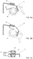
FIG. 3A is a close up view of the non-contact switch device area circled inFIG. 3 when the operator handle is in the generally vertical or fully upright parked position A, with the non-contact switch device in the off position. -
FIG. 3B is a close up view of the non-contact switch device area circled inFIG. 3 when in the operator handle is in the angled operating position B, with the non-contact switch device in the on position. -
FIG. 3C is a close up view of the non-contact switch device area circled inFIG. 3 when the operator handle is in the generally horizontal or fully lowered inactive position A, with the non-contact switch device in the off position. -
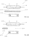
FIG. 4A is a schematic view corresponding to the open position of the non-contact switch device inFIGS. 3A and 3C , showing the reed switch elements disengaged, which occurs when a shielding member is located between the magnet and the reed switch. -
FIG. 4B is a schematic view corresponding to the closed position of the non-contact switch device inFIG. 3B , showing the reed switch elements engaged, which occurs when the shielding member is not located between the magnet and the reed switch. -
FIG. 5 is a side view of the example pallet truck with the load lift portion in a lowered position A in the upper view, and in a preselected uppermost raised position B in the lower view, with the non-contact switch device area shown in a circle and the non-contact switch device functioning as a limit switch. -
FIG. 5A is a close up side view of the non-contact switch device area circled inFIG. 5 when the load lift portion is in the lowered position A, with the non-contact switch device in the on position as the shielding member is not located between the magnet and the reed switch. -
FIG. 5B is a close up side view of the non-contact switch device area circled inFIG. 5 when the load lift portion is in the preselected uppermost raised position B, with the non-contact switch device in the off position as the shielding member is located between the magnet and the reed switch. -
FIG. 5C is a close up top view of the non-contact switch device area circled inFIG. 5 when in the load lift portion is in the preselected uppermost raised position B, with the non-contact switch device in the off position as the shielding member is located between the magnet and the reed switch. - It should be understood that the drawings are not necessarily to scale. While some details of the material handling equipment, and other plan and section views of the particular components have been omitted, such details are considered to be within the comprehension of those skilled in the art in light of the present disclosure. It also should be understood that the present disclosure is not limited to the examples illustrated and described.
- This disclosure provides solutions to the technical problems presented by electrical switches commonly used for various functions when operating material handling equipment, such as are used in pallet trucks, pallet stackers and the like. Examples of non-contact switch devices that realize switch on and off positions by the presence or absence of magnetic induction between a magnet and a reed switch are shown in various forms in
FIGS. 1A-5C for use on material handling equipment, such as a pallet truck. The non-contact switch devices are shown for example in the form of amain power switch 1 for a pallet truck inFIGS. 1A-1C , with a schematic view of the reed switch elements of that non-contact switch device inFIGS. 2A-2B , in the form of aninterlock switch 20 on a handle of a pallet truck inFIGS. 3 and 3A-3C , with a schematic view of the reed switch elements of that non-contact switch device inFIGS. 4A-4B , and in the form of alimit switch 40 associated with movement of the load lift portion of the pallet truck inFIGS. 5 and5A-5B , which also is represented by the schematic view of the reed switch elements of that non-contact switch device inFIGS. 4A-4B . - The
non-contact switch devices non-contact switch device 1 represented inFIGS. 1A-1C and2A-2B . Alternatively, the reed switch elements may be predisposed to normally be closed or touching together when not in the presence of a magnet, so as to open or move to be spaced apart in the presence of a magnet, such as in thenon-contact switch devices FIGS. 3 and 3A-3C ,4A-4B ,5 and5A-5C . It will be appreciated that the reed switch may be designed to have one or both reeds move when subjected to a magnetic force. - As shown in
FIGS. 1A-1C , the disclosure provides a first examplenon-contact switch 1 that is a main power switch, which includes amagnet 2 and areed switch 3. Thereed switch 3 is held within and connected to aswitch body 4 that includes aswitch socket 5 and may be mounted on a surface of material handling equipment for convenient acccss by an operator, such as on a top surface of a pallet truck or the like. Themagnet 2 may be a permanent magnet and is held or embedded within amagnet cap 6, which simply otherwise may be constructed of plastic and which is removably receivable in theswitch socket 5. - As seen in the schematic view in
FIGS. 2A and 2B , thereed switch 3 includesreed elements chamber 9. In this example, as seen inFIG. 2A , thenon-contact switch device 1 is normally in an open position because thereed elements magnet 2. When themagnet cap 6 is placed in theswitch socket 5, themagnet 2 is brought into close proximity of thereed switch 3. The magnetic field caused by the presence of themagnet 2 causes thereed element 7 to be attracted to and move toward themagnet 2, which results in thereed element 7 moving into contact with thereed element 8, closing thereed switch 3 and thereby moving thenon-contact switch device 1 to an on position. - The
non-contact switch device 1 including themagnet 2 andmagnetic reed switch 3 preferably provides an easier structure to employ, requires a smaller volume, is actuated at a faster speed, and yields a longer service life than traditional mechanical switches used on material handling equipment. Thenon-contact switch device 1 also has stronger resistance and is more reliable than electric switches. Its switchingreed elements - Thus, a first example
non-contact switch device 1 is represented inFIGS. 1A-1C and 2A-2B. Thenon-contact switch device 1 for use on material handling equipment includes amagnet 2 and areed switch 3, wherein thenon-contact switch device 1 has on and off positions achieved by the presence or absence of magnetic induction between themagnet 2 and thereed switch 3. Thenon-contact switch device 1 is in the on position when themagnet 2 is placed in close proximity to thereed switch 3, and is in the off position when themagnet 2 is not in close proximity to thereed switch 3. - The example
non-contact switch device 1 has themagnet cap 6 that includes themagnet 2 and theswitch socket 5 that includes thereed switch 3. When themagnet cap 6 is placed in theswitch socket 5, themagnet 2 is in close proximity to thereed switch 3 and thenon-contact switch device 1 is in the on position. When themagnet cap 6 is removed from theswitch socket 5, themagnet 2 is not in close proximity to thereed switch 3 and thenon-contact switch device 1 is in the off position. In light of this disclosure, it will be appreciated that with thenon-contact switch device 1 of the first example, themagnet cap 6 and switchsocket 5 are part of a main power switch device for material handling equipment, such as a pallet truck, with the main power switch having a power on and off function corresponding to the on and off positions, wherein themagnet cap 6 may simply be removed and placed in a pocket when the equipment is not in use. - As shown in
FIGS. 3 and 3A-3C , the disclosure provides a second examplenon-contact switch 20 wherein amagnet 22 and areed switch 23 are in a spaced apart position and thenon-contact switch device 20 is in the off position when a shieldingmember 21 is located between themagnet 22 and thereed switch 23, and is in the on position when the shieldingmember 21 is not located between themagnet 22 and thereed switch 23. The second examplenon-contact switch device 20 is in the form of an interlock switch. Themagnet 22 andreed switch 23 may be connected to the same component, such as a bracket, and are connected to abase portion 24 of a pallet truck P and are spaced apart by a gap 25. Themagnet 22 may be a permanent magnet. The shieldingmember 21 is connected to anoperator handle 26 that pivots relative to thebase portion 24, and the shieldingmember 21 has more than one extensions that act as a shield. - With the second example
non-contact switch device 20, themagnet 22 and thereed switch 23 are spaced apart by the gap 25 and thenon-contact switch device 20 is in the off position when the shieldingmember 21 is located between themagnet 22 and thereed switch 23, and is in the on position when the shieldingmember 21 is not located between themagnet 22 and thereed switch 23. - As seen in the schematic view in
FIGS. 4A and 4B , thereed switch 23 includesreed elements chamber 29. In this example, as seen inFIG. 4B , thenon-contact switch device 20, which has themagnet 22 andreed switch 23 in fixed positions with the gap 25 therebetween, normally is in a closed position because themagnet 22 attracts thereed element 27 toward and into contact with thereed elements 28. When the shieldingelement 21 is moved to be located in the gap 25 between themagnet 22 and thereed switch 23, as seen inFIG. 4A , thereed element 27 returns to a pre-deflected position spaced apart fromreed element 28, opening thereed switch 23, so as to be moved to the off position. - While this second example
non-contact switch device 20 includes a shieldingmember 21, it will be appreciated that thenon-contact switch device 20 also operates in response to the presence or absence of a magnetic field between themagnet 22 and thereed switch 23.FIG. 3 is a side view of the pallet truck P showing the operator handle 26 in three example positions A, B and C, which provide different operational states of thenon-contact switch device 20 in the form of an interlock switch. - The example pallet truck P is shown with the operator handle in a generally vertical parked position A, an angled operating position B, and a generally horizontal inactive position C. A close up view of the
non-contact switch device 20 inFIG. 3A corresponds to the generally parked position A of theoperator handle 26. With the operator handle 26 essentially fully upright in a parked position, the shieldingmember 21 is located between themagnet 22 and thereed switch 23, placing thenon-contact switch device 20 in an open position, as shown inFIG. 4A . With thereed elements reed switch 23 and a controller prevents the pallet truck P from being driven. - When an operator wishes to drive the pallet truck P, the operator may grasp the operator handle 26 and tilt it to an inclined operating position, such as position B. The operating position generally may be at an angular position anywhere between the generally vertical or fully upright position A and the generally horizontal or fully lowered position C. In an operating position B, the shielding
member 21 that is connected to the operator handle 26 is moved so as to no longer be located in the gap 25 between themagnet 22 and thereed switch 23, as represented inFIGS. 3B and4B . This permits thereed switch 23 to close, which corresponds to being in the on position shown inFIG. 4B , wherein power is able to flow through thereed switch 23 and a controller makes the pallet truck P drivable. Thus, the operator is able to utilize the controls on the operator handle 26 to operate and drive the pallet truck P. - If the operator were to inadvertently drop the
operator handle 26, it would move to the generally horizontal, fully lowered position C, shown inFIG. 3 . This would result in thenon-contact switch device 20 being in the position shown inFIG. 3C , wherein another shieldingmember 21 on the operator handle 26 is moved to be located in the gap 25 between themagnet 22 and thereed switch 23. Thus, as a safety precaution, thenon-contact switch device 20 would be opened and moved to the off position, rendering the drive system inactive when the operator handle is moved to a generally horizontal position C. - As shown in
FIGS. 5 and5A-5C , the disclosure provides a third examplenon-contact switch 40 wherein amagnet 42 and areed switch 43 are in a spaced apart position and thenon-contact switch device 40 is in the off position when a shieldingmember 41 is located between themagnet 42 and thereed switch 43, and is in the on position when the shieldingmember 41 is not located between themagnet 42 and thereed switch 43. The third examplenon-contact switch device 40 is in the form of a limit switch. Themagnet 42 andreed switch 43 may be connected to the same component, such as a bracket, and are connected to aload lift portion 44 of a pallet truck P and are spaced apart by agap 45. Themagnet 42 may be a permanent magnet. The shieldingmember 41 is connected to arotating link 46 that pivots relative to theload lift portion 44 as theload lift portion 44 is raised or lowered. - With the third example
non-contact switch device 40, themagnet 42 and thereed switch 43 are spaced apart by thegap 45 and thenon-contact switch device 40 is in the on position when the shieldingmember 41 is not located between themagnet 42 and thereed switch 43, and is in the off position when the shieldingmember 41 is located between themagnet 42 and thereed switch 43. - As seen in the schematic view in
FIGS. 4A and 4B , and similar to the second example, thereed switch 43 of the third example includesreed elements chamber 29. In this third example,FIG. 5 shows a lowered position A of theload lift portion 44, which corresponds to the position shown inFIG. 5A . This further corresponds to the schematic view seen inFIG. 4B where thenon-contact switch device 40 is in the on position, which permits an operator to raise theload lift portion 44. Theload lift portion 44 may be raised to a preselected position, such as the position B shown inFIG. 5 . The raised position B inFIG. 5 corresponds to the position of thenon-contact switch device 40 shown inFIGS. 5B and 5C , where thelink 46 has rotated sufficiently to cause the shieldingmember 41 to move to a location in thegap 45 between themagnet 42 and thereed switch 43. This further corresponds to the schematic view seen inFIG. 4A where thenon-contact switch device 40 is in the off position, which stops the risingload lift portion 44 at a preselected uppermost raised position, which represents a limit of travel. - The
magnet 42 andreed switch 43 are in fixed positions with thegap 45 therebetween, and when theload lift portion 44 is in the lowered position, thenon-contact switch device 40 normally is in a closed position because themagnet 42 attracts thereed element 27 toward and into contact with thereed elements 28, as shown inFIG. 4B . When thelink 46 rotates as theload lift portion 44 is raised, the shieldingelement 41 is moved to be located in thegap 45 between themagnet 42 and thereed switch 43, as seen inFIG. 4A , where thereed element 27 returns to a pre-deflected position spaced apart fromreed element 28, opening thereed switch 43, so as to be moved to the off position. - While this third example
non-contact switch device 40 includes a shieldingmember 41, it will be appreciated that thenon-contact switch device 40 also operates in response to the presence or absence of a magnetic field between themagnet 42 and thereed switch 43. - As explained in the foregoing, the reed switch and magnet of the non-contact switch device of the invention may be in a spaced apart position, wherein it is possible for the non-contact switch device to be in the off position when a shielding member is located between the magnet and the reed switch, and to be in the on position when the shielding member is not located between the magnet and the reed switch. In such a case, the non-contact switch device may be part of a pallet truck having an operator handle and may be in the off position with the shielding member located between the magnet and the reed switch when the operator handle is in a generally vertical position, wherein it also may be so that the pallet truck is in a parked position when the operator handle is in the generally vertical position. Further, the non-contact switch device may be part of a pallet truck having an operator handle and may be in the on position with the shielding member not located between the magnet and the reed switch when the operator handle is in a generally inclined operating position, wherein it also may be so that when the operator handle is in the generally inclined operating position, the pallet truck is drivable. Still further, the non-contact switch device may be part of a pallet truck having an operator handle and may be in the off position with the shielding member located between the magnet and the reed switch when the operator handle is in a generally horizontal position, wherein it also may be so that the operator handle is in an inactive position when the operator handle has been moved to the generally horizontal position.
- The above description is provided with respect to preferred examples of the non-contact switch devices for use on material handling equipment, such as pallet trucks, pallet stackers and the like. It will be appreciated, however, that the invention may be constructed and configured in various ways and is not limited to the specific examples shown and described herein, and its use is not limited to pallet trucks.
- Thus, the present disclosure presents alternatives to traditional switches used on prior art material handling equipment. The non-contact switch devices provide advantageous features by permitting more compact, reliable switches that are less susceptible to wear, corrosion and issues that shorten switch service life. This results in lower costs and less downtime for maintenance or switch replacement.
- It will be appreciated that the present disclosure shows and demonstrates preferred examples of non-contact switch devices for use on material handling equipment, which is discussed in the context of an example pallet truck, a pallet stacker or other material handling equipment. Indeed, these examples are merely illustrative and are not to be considered limiting. It will be apparent to those of ordinary skill in the art that the devices may be constructed and configured for use in various material handling equipment.
Claims (5)
- A pallet truck (P) comprising:an operator handle (26); anda non-contact switch device (20) comprising a magnet (22) and a reed switch (23),wherein the non-contact switch device has on and off positions that are achievable by the presence or absence of magnetic induction between the magnet and the reed switch,wherein the reed switch and magnet of the non-contact switch device are in a spaced apart position and the non-contact switch device is in the off position when a shielding member (21) is located between the magnet and the reed switch, and is in the on position when the shielding member is not located between the magnet and the reed switch,wherein the non-contact switch device is in the off position with the shielding member located between the magnet and the reed switch when the operator handle is in a generally vertical position, andwherein the shielding member has more than one extensions that act as a shield.
- The pallet truck according to claim 1, wherein the non-contact switch device is part of an interlock switch.
- The pallet truck according to claim 1 or 2, wherein the magnet and reed switch are connected to a base portion (24) and the shielding member is connected to the operator handle that pivots relative to the base portion.
- The pallet truck according to any of claims 1-3, wherein the non-contact switch device is in the on position with the shielding member not located between the magnet and the reed switch when the operator handle is in a generally inclined operating position.
- The pallet truck according to any of claims 1-3, wherein the non-contact switch device is in the off position with the shielding member located between the magnet and the reed switch when the operator handle is in a generally horizontal position.
Applications Claiming Priority (1)
| Application Number | Priority Date | Filing Date | Title |
|---|---|---|---|
| US15/393,428 US10014141B1 (en) | 2016-12-29 | 2016-12-29 | Non-contact switch devices for use on material handling equipment |
Publications (2)
| Publication Number | Publication Date |
|---|---|
| EP3343584A1 EP3343584A1 (en) | 2018-07-04 |
| EP3343584B1 true EP3343584B1 (en) | 2021-04-07 |
Family
ID=58046539
Family Applications (1)
| Application Number | Title | Priority Date | Filing Date |
|---|---|---|---|
| EP17156115.2A Active EP3343584B1 (en) | 2016-12-29 | 2017-02-14 | Non-contact switch devices for use on material handling equipment |
Country Status (2)
| Country | Link |
|---|---|
| US (1) | US10014141B1 (en) |
| EP (1) | EP3343584B1 (en) |
Families Citing this family (5)
| Publication number | Priority date | Publication date | Assignee | Title |
|---|---|---|---|---|
| JP7300400B2 (en) * | 2020-01-10 | 2023-06-29 | 株式会社エクセディ | drive unit |
| CN215364722U (en) | 2021-06-26 | 2021-12-31 | 浙江中力机械股份有限公司 | Carrier vehicle |
| CN216133771U (en) * | 2021-06-26 | 2022-03-25 | 浙江中力机械股份有限公司 | Handle joint seat and carrier control handle |
| CN114890344B (en) * | 2022-04-24 | 2025-04-22 | 宁波如意股份有限公司 | A foldable manual pallet truck |
| US11673736B1 (en) | 2022-04-29 | 2023-06-13 | Zhejiang E-P Eouipment Co., Ltd. | Packing systems and methods for shipping pallet truck vehicles |
Citations (1)
| Publication number | Priority date | Publication date | Assignee | Title |
|---|---|---|---|---|
| US20050016779A1 (en) * | 2003-07-25 | 2005-01-27 | Lindsay Ryan Philip | Pallet truck tiller arm with angle detector for speed select |
Family Cites Families (18)
| Publication number | Priority date | Publication date | Assignee | Title |
|---|---|---|---|---|
| US2913062A (en) * | 1957-12-03 | 1959-11-17 | Yale & Towne Mfg Co | Rider operated control for pedestrian truck |
| US3009033A (en) * | 1959-04-20 | 1961-11-14 | Gen Electric | Limit switches |
| US3164696A (en) * | 1961-08-04 | 1965-01-05 | Gen Electric | Vane operated magnetic reed switch |
| US3803575A (en) * | 1971-02-15 | 1974-04-09 | M Gotanda | Device for setting-up a power source of electrical alarm |
| US3896892A (en) * | 1973-09-20 | 1975-07-29 | Webb Co Jervis B | Manual control for a self-propelled vehicle |
| JPS6329850U (en) * | 1986-08-11 | 1988-02-26 | ||
| JPH0761790A (en) * | 1993-08-27 | 1995-03-07 | Mitsubishi Heavy Ind Ltd | Control device for forklift |
| US5541562A (en) * | 1994-10-16 | 1996-07-30 | Honeywell Inc. | Apparatus for sensing the closure of a door |
| US6124792A (en) * | 1998-11-25 | 2000-09-26 | U-Haul International, Inc. | Latch integrated, tamper resistant, electro-magnetic alarm switch |
| US6359538B1 (en) * | 2000-09-12 | 2002-03-19 | Daniel M. Jolley | Bracket assembly for mounting a reed switch and associated magnet |
| JP3858967B2 (en) * | 2000-12-15 | 2006-12-20 | 日産自動車株式会社 | Reach-type forklift rear wheel suspension system |
| JP4500472B2 (en) * | 2001-08-13 | 2010-07-14 | アルプス電気株式会社 | Magnetic switch and magnetic sensor |
| JP3776772B2 (en) * | 2001-08-22 | 2006-05-17 | 本田技研工業株式会社 | Electric lawn mower |
| US8111119B2 (en) * | 2003-02-19 | 2012-02-07 | Gilmore Glendell N | Reed switch apparatus and method of using same |
| US20060231301A1 (en) * | 2005-04-19 | 2006-10-19 | Rose Timothy L | Coast control for motorized pallet truck |
| DE202005013065U1 (en) * | 2005-08-18 | 2007-01-04 | Liebherr-Hausgeräte Ochsenhausen GmbH | Refrigerator door position sensor has magnet fields influenced by relative movement of ferromagnetic plate moved by lip to control switch settings |
| US9241441B2 (en) * | 2012-02-22 | 2016-01-26 | Husqvarna Ab | Robotic lawnmower |
| DE102014107082A1 (en) * | 2014-05-20 | 2015-11-26 | Jungheinrich Aktiengesellschaft | Truck with ramp lift function |
-
2016
- 2016-12-29 US US15/393,428 patent/US10014141B1/en active Active
-
2017
- 2017-02-14 EP EP17156115.2A patent/EP3343584B1/en active Active
Patent Citations (1)
| Publication number | Priority date | Publication date | Assignee | Title |
|---|---|---|---|---|
| US20050016779A1 (en) * | 2003-07-25 | 2005-01-27 | Lindsay Ryan Philip | Pallet truck tiller arm with angle detector for speed select |
Also Published As
| Publication number | Publication date |
|---|---|
| EP3343584A1 (en) | 2018-07-04 |
| US20180190454A1 (en) | 2018-07-05 |
| US10014141B1 (en) | 2018-07-03 |
Similar Documents
| Publication | Publication Date | Title |
|---|---|---|
| US10014141B1 (en) | Non-contact switch devices for use on material handling equipment | |
| CN105433859A (en) | Self-Propelled Working Device | |
| US3753265A (en) | Translatable suction cleaning vehicle | |
| KR20010020483A (en) | Device for a materials handling vehicle | |
| CN108516505A (en) | Fork truck work safety control and control method | |
| EP0911295B1 (en) | Clamp assembly with automatic rotation control | |
| US5088879A (en) | Forward tilt limit system for lift trucks | |
| AU2003200364A1 (en) | Load control system for tandem pallet truck | |
| WO2021081336A1 (en) | A portable vacuum lifter system | |
| US3907141A (en) | Operator{3 s station optionally stationary or elevated | |
| JP7178359B2 (en) | A linear actuator system that moves the tines of a work vehicle | |
| CN206516563U (en) | Carrier and the non-contact switch apparatus on carrier | |
| JP3773561B2 (en) | Wafer processing equipment | |
| JP6555766B2 (en) | forklift | |
| CN106744505A (en) | An automatic guided transport vehicle | |
| CN110550124A (en) | Transport mechanism | |
| CN110562882A (en) | An AGV trolley using electromagnetic hydraulic jacking | |
| JPH0210881Y2 (en) | ||
| JP6355143B1 (en) | forklift | |
| CN108253735B (en) | Safety device for vacuum drying tank and vacuum drying tank | |
| CN110509305A (en) | Excavator with permanent magnetic adsorption mechanism | |
| CN107380952B (en) | A kind of alarm protecting apparatus for tipping-bucket hoisting machine | |
| CN1105077C (en) | Position detecting apparatus for forklifts | |
| KR20160115968A (en) | Working vehicle | |
| JPH0826695A (en) | Safety device for order-picker |
Legal Events
| Date | Code | Title | Description |
|---|---|---|---|
| PUAI | Public reference made under article 153(3) epc to a published international application that has entered the european phase |
Free format text: ORIGINAL CODE: 0009012 |
|
| STAA | Information on the status of an ep patent application or granted ep patent |
Free format text: STATUS: THE APPLICATION HAS BEEN PUBLISHED |
|
| AK | Designated contracting states |
Kind code of ref document: A1 Designated state(s): AL AT BE BG CH CY CZ DE DK EE ES FI FR GB GR HR HU IE IS IT LI LT LU LV MC MK MT NL NO PL PT RO RS SE SI SK SM TR |
|
| AX | Request for extension of the european patent |
Extension state: BA ME |
|
| STAA | Information on the status of an ep patent application or granted ep patent |
Free format text: STATUS: REQUEST FOR EXAMINATION WAS MADE |
|
| 17P | Request for examination filed |
Effective date: 20181221 |
|
| RBV | Designated contracting states (corrected) |
Designated state(s): AL AT BE BG CH CY CZ DE DK EE ES FI FR GB GR HR HU IE IS IT LI LT LU LV MC MK MT NL NO PL PT RO RS SE SI SK SM TR |
|
| STAA | Information on the status of an ep patent application or granted ep patent |
Free format text: STATUS: EXAMINATION IS IN PROGRESS |
|
| 17Q | First examination report despatched |
Effective date: 20190227 |
|
| GRAP | Despatch of communication of intention to grant a patent |
Free format text: ORIGINAL CODE: EPIDOSNIGR1 |
|
| STAA | Information on the status of an ep patent application or granted ep patent |
Free format text: STATUS: GRANT OF PATENT IS INTENDED |
|
| INTG | Intention to grant announced |
Effective date: 20201019 |
|
| GRAS | Grant fee paid |
Free format text: ORIGINAL CODE: EPIDOSNIGR3 |
|
| GRAA | (expected) grant |
Free format text: ORIGINAL CODE: 0009210 |
|
| STAA | Information on the status of an ep patent application or granted ep patent |
Free format text: STATUS: THE PATENT HAS BEEN GRANTED |
|
| AK | Designated contracting states |
Kind code of ref document: B1 Designated state(s): AL AT BE BG CH CY CZ DE DK EE ES FI FR GB GR HR HU IE IS IT LI LT LU LV MC MK MT NL NO PL PT RO RS SE SI SK SM TR |
|
| REG | Reference to a national code |
Ref country code: GB Ref legal event code: FG4D |
|
| REG | Reference to a national code |
Ref country code: AT Ref legal event code: REF Ref document number: 1380770 Country of ref document: AT Kind code of ref document: T Effective date: 20210415 Ref country code: CH Ref legal event code: EP |
|
| REG | Reference to a national code |
Ref country code: DE Ref legal event code: R096 Ref document number: 602017036003 Country of ref document: DE |
|
| REG | Reference to a national code |
Ref country code: IE Ref legal event code: FG4D |
|
| REG | Reference to a national code |
Ref country code: LT Ref legal event code: MG9D |
|
| REG | Reference to a national code |
Ref country code: NL Ref legal event code: MP Effective date: 20210407 Ref country code: AT Ref legal event code: MK05 Ref document number: 1380770 Country of ref document: AT Kind code of ref document: T Effective date: 20210407 |
|
| PG25 | Lapsed in a contracting state [announced via postgrant information from national office to epo] |
Ref country code: NL Free format text: LAPSE BECAUSE OF FAILURE TO SUBMIT A TRANSLATION OF THE DESCRIPTION OR TO PAY THE FEE WITHIN THE PRESCRIBED TIME-LIMIT Effective date: 20210407 Ref country code: HR Free format text: LAPSE BECAUSE OF FAILURE TO SUBMIT A TRANSLATION OF THE DESCRIPTION OR TO PAY THE FEE WITHIN THE PRESCRIBED TIME-LIMIT Effective date: 20210407 Ref country code: AT Free format text: LAPSE BECAUSE OF FAILURE TO SUBMIT A TRANSLATION OF THE DESCRIPTION OR TO PAY THE FEE WITHIN THE PRESCRIBED TIME-LIMIT Effective date: 20210407 Ref country code: BG Free format text: LAPSE BECAUSE OF FAILURE TO SUBMIT A TRANSLATION OF THE DESCRIPTION OR TO PAY THE FEE WITHIN THE PRESCRIBED TIME-LIMIT Effective date: 20210707 Ref country code: FI Free format text: LAPSE BECAUSE OF FAILURE TO SUBMIT A TRANSLATION OF THE DESCRIPTION OR TO PAY THE FEE WITHIN THE PRESCRIBED TIME-LIMIT Effective date: 20210407 Ref country code: LT Free format text: LAPSE BECAUSE OF FAILURE TO SUBMIT A TRANSLATION OF THE DESCRIPTION OR TO PAY THE FEE WITHIN THE PRESCRIBED TIME-LIMIT Effective date: 20210407 |
|
| PG25 | Lapsed in a contracting state [announced via postgrant information from national office to epo] |
Ref country code: NO Free format text: LAPSE BECAUSE OF FAILURE TO SUBMIT A TRANSLATION OF THE DESCRIPTION OR TO PAY THE FEE WITHIN THE PRESCRIBED TIME-LIMIT Effective date: 20210707 Ref country code: PL Free format text: LAPSE BECAUSE OF FAILURE TO SUBMIT A TRANSLATION OF THE DESCRIPTION OR TO PAY THE FEE WITHIN THE PRESCRIBED TIME-LIMIT Effective date: 20210407 Ref country code: PT Free format text: LAPSE BECAUSE OF FAILURE TO SUBMIT A TRANSLATION OF THE DESCRIPTION OR TO PAY THE FEE WITHIN THE PRESCRIBED TIME-LIMIT Effective date: 20210809 Ref country code: RS Free format text: LAPSE BECAUSE OF FAILURE TO SUBMIT A TRANSLATION OF THE DESCRIPTION OR TO PAY THE FEE WITHIN THE PRESCRIBED TIME-LIMIT Effective date: 20210407 Ref country code: SE Free format text: LAPSE BECAUSE OF FAILURE TO SUBMIT A TRANSLATION OF THE DESCRIPTION OR TO PAY THE FEE WITHIN THE PRESCRIBED TIME-LIMIT Effective date: 20210407 Ref country code: GR Free format text: LAPSE BECAUSE OF FAILURE TO SUBMIT A TRANSLATION OF THE DESCRIPTION OR TO PAY THE FEE WITHIN THE PRESCRIBED TIME-LIMIT Effective date: 20210708 Ref country code: IS Free format text: LAPSE BECAUSE OF FAILURE TO SUBMIT A TRANSLATION OF THE DESCRIPTION OR TO PAY THE FEE WITHIN THE PRESCRIBED TIME-LIMIT Effective date: 20210807 Ref country code: LV Free format text: LAPSE BECAUSE OF FAILURE TO SUBMIT A TRANSLATION OF THE DESCRIPTION OR TO PAY THE FEE WITHIN THE PRESCRIBED TIME-LIMIT Effective date: 20210407 |
|
| REG | Reference to a national code |
Ref country code: DE Ref legal event code: R097 Ref document number: 602017036003 Country of ref document: DE |
|
| PG25 | Lapsed in a contracting state [announced via postgrant information from national office to epo] |
Ref country code: SM Free format text: LAPSE BECAUSE OF FAILURE TO SUBMIT A TRANSLATION OF THE DESCRIPTION OR TO PAY THE FEE WITHIN THE PRESCRIBED TIME-LIMIT Effective date: 20210407 Ref country code: SK Free format text: LAPSE BECAUSE OF FAILURE TO SUBMIT A TRANSLATION OF THE DESCRIPTION OR TO PAY THE FEE WITHIN THE PRESCRIBED TIME-LIMIT Effective date: 20210407 Ref country code: CZ Free format text: LAPSE BECAUSE OF FAILURE TO SUBMIT A TRANSLATION OF THE DESCRIPTION OR TO PAY THE FEE WITHIN THE PRESCRIBED TIME-LIMIT Effective date: 20210407 Ref country code: EE Free format text: LAPSE BECAUSE OF FAILURE TO SUBMIT A TRANSLATION OF THE DESCRIPTION OR TO PAY THE FEE WITHIN THE PRESCRIBED TIME-LIMIT Effective date: 20210407 Ref country code: DK Free format text: LAPSE BECAUSE OF FAILURE TO SUBMIT A TRANSLATION OF THE DESCRIPTION OR TO PAY THE FEE WITHIN THE PRESCRIBED TIME-LIMIT Effective date: 20210407 Ref country code: RO Free format text: LAPSE BECAUSE OF FAILURE TO SUBMIT A TRANSLATION OF THE DESCRIPTION OR TO PAY THE FEE WITHIN THE PRESCRIBED TIME-LIMIT Effective date: 20210407 Ref country code: ES Free format text: LAPSE BECAUSE OF FAILURE TO SUBMIT A TRANSLATION OF THE DESCRIPTION OR TO PAY THE FEE WITHIN THE PRESCRIBED TIME-LIMIT Effective date: 20210407 |
|
| PLBE | No opposition filed within time limit |
Free format text: ORIGINAL CODE: 0009261 |
|
| STAA | Information on the status of an ep patent application or granted ep patent |
Free format text: STATUS: NO OPPOSITION FILED WITHIN TIME LIMIT |
|
| 26N | No opposition filed |
Effective date: 20220110 |
|
| PG25 | Lapsed in a contracting state [announced via postgrant information from national office to epo] |
Ref country code: IS Free format text: LAPSE BECAUSE OF FAILURE TO SUBMIT A TRANSLATION OF THE DESCRIPTION OR TO PAY THE FEE WITHIN THE PRESCRIBED TIME-LIMIT Effective date: 20210807 Ref country code: AL Free format text: LAPSE BECAUSE OF FAILURE TO SUBMIT A TRANSLATION OF THE DESCRIPTION OR TO PAY THE FEE WITHIN THE PRESCRIBED TIME-LIMIT Effective date: 20210407 |
|
| PG25 | Lapsed in a contracting state [announced via postgrant information from national office to epo] |
Ref country code: IT Free format text: LAPSE BECAUSE OF FAILURE TO SUBMIT A TRANSLATION OF THE DESCRIPTION OR TO PAY THE FEE WITHIN THE PRESCRIBED TIME-LIMIT Effective date: 20210407 |
|
| PG25 | Lapsed in a contracting state [announced via postgrant information from national office to epo] |
Ref country code: MC Free format text: LAPSE BECAUSE OF FAILURE TO SUBMIT A TRANSLATION OF THE DESCRIPTION OR TO PAY THE FEE WITHIN THE PRESCRIBED TIME-LIMIT Effective date: 20210407 |
|
| REG | Reference to a national code |
Ref country code: CH Ref legal event code: PL |
|
| REG | Reference to a national code |
Ref country code: BE Ref legal event code: MM Effective date: 20220228 |
|
| PG25 | Lapsed in a contracting state [announced via postgrant information from national office to epo] |
Ref country code: LU Free format text: LAPSE BECAUSE OF NON-PAYMENT OF DUE FEES Effective date: 20220214 |
|
| PG25 | Lapsed in a contracting state [announced via postgrant information from national office to epo] |
Ref country code: LI Free format text: LAPSE BECAUSE OF NON-PAYMENT OF DUE FEES Effective date: 20220228 Ref country code: IE Free format text: LAPSE BECAUSE OF NON-PAYMENT OF DUE FEES Effective date: 20220214 Ref country code: CH Free format text: LAPSE BECAUSE OF NON-PAYMENT OF DUE FEES Effective date: 20220228 |
|
| PG25 | Lapsed in a contracting state [announced via postgrant information from national office to epo] |
Ref country code: BE Free format text: LAPSE BECAUSE OF NON-PAYMENT OF DUE FEES Effective date: 20220228 |
|
| P01 | Opt-out of the competence of the unified patent court (upc) registered |
Effective date: 20230424 |
|
| PG25 | Lapsed in a contracting state [announced via postgrant information from national office to epo] |
Ref country code: HU Free format text: LAPSE BECAUSE OF FAILURE TO SUBMIT A TRANSLATION OF THE DESCRIPTION OR TO PAY THE FEE WITHIN THE PRESCRIBED TIME-LIMIT; INVALID AB INITIO Effective date: 20170214 |
|
| PG25 | Lapsed in a contracting state [announced via postgrant information from national office to epo] |
Ref country code: MK Free format text: LAPSE BECAUSE OF FAILURE TO SUBMIT A TRANSLATION OF THE DESCRIPTION OR TO PAY THE FEE WITHIN THE PRESCRIBED TIME-LIMIT Effective date: 20210407 Ref country code: CY Free format text: LAPSE BECAUSE OF FAILURE TO SUBMIT A TRANSLATION OF THE DESCRIPTION OR TO PAY THE FEE WITHIN THE PRESCRIBED TIME-LIMIT Effective date: 20210407 |
|
| PGFP | Annual fee paid to national office [announced via postgrant information from national office to epo] |
Ref country code: DE Payment date: 20240227 Year of fee payment: 8 Ref country code: GB Payment date: 20240226 Year of fee payment: 8 |
|
| PGFP | Annual fee paid to national office [announced via postgrant information from national office to epo] |
Ref country code: FR Payment date: 20240208 Year of fee payment: 8 |
|
| PG25 | Lapsed in a contracting state [announced via postgrant information from national office to epo] |
Ref country code: TR Free format text: LAPSE BECAUSE OF FAILURE TO SUBMIT A TRANSLATION OF THE DESCRIPTION OR TO PAY THE FEE WITHIN THE PRESCRIBED TIME-LIMIT Effective date: 20210407 |
|
| PG25 | Lapsed in a contracting state [announced via postgrant information from national office to epo] |
Ref country code: MT Free format text: LAPSE BECAUSE OF FAILURE TO SUBMIT A TRANSLATION OF THE DESCRIPTION OR TO PAY THE FEE WITHIN THE PRESCRIBED TIME-LIMIT Effective date: 20210407 |
|
| REG | Reference to a national code |
Ref country code: DE Ref legal event code: R119 Ref document number: 602017036003 Country of ref document: DE |
|
| GBPC | Gb: european patent ceased through non-payment of renewal fee |
Effective date: 20250214 |
|
| PG25 | Lapsed in a contracting state [announced via postgrant information from national office to epo] |
Ref country code: DE Free format text: LAPSE BECAUSE OF NON-PAYMENT OF DUE FEES Effective date: 20250902 |
|
| PG25 | Lapsed in a contracting state [announced via postgrant information from national office to epo] |
Ref country code: GB Free format text: LAPSE BECAUSE OF NON-PAYMENT OF DUE FEES Effective date: 20250214 |
|
| PG25 | Lapsed in a contracting state [announced via postgrant information from national office to epo] |
Ref country code: FR Free format text: LAPSE BECAUSE OF NON-PAYMENT OF DUE FEES Effective date: 20250228 |