EP3343575B1 - A pressure compensator of a subsea installation - Google Patents
A pressure compensator of a subsea installation Download PDFInfo
- Publication number
- EP3343575B1 EP3343575B1 EP16207075.9A EP16207075A EP3343575B1 EP 3343575 B1 EP3343575 B1 EP 3343575B1 EP 16207075 A EP16207075 A EP 16207075A EP 3343575 B1 EP3343575 B1 EP 3343575B1
- Authority
- EP
- European Patent Office
- Prior art keywords
- fluid
- subsea installation
- heating
- installation according
- subsea
- Prior art date
- Legal status (The legal status is an assumption and is not a legal conclusion. Google has not performed a legal analysis and makes no representation as to the accuracy of the status listed.)
- Active
Links
Images


Classifications
-
- H—ELECTRICITY
- H01—ELECTRIC ELEMENTS
- H01F—MAGNETS; INDUCTANCES; TRANSFORMERS; SELECTION OF MATERIALS FOR THEIR MAGNETIC PROPERTIES
- H01F27/00—Details of transformers or inductances, in general
- H01F27/008—Details of transformers or inductances, in general with temperature compensation
-
- H—ELECTRICITY
- H05—ELECTRIC TECHNIQUES NOT OTHERWISE PROVIDED FOR
- H05K—PRINTED CIRCUITS; CASINGS OR CONSTRUCTIONAL DETAILS OF ELECTRIC APPARATUS; MANUFACTURE OF ASSEMBLAGES OF ELECTRICAL COMPONENTS
- H05K5/00—Casings, cabinets or drawers for electric apparatus
- H05K5/06—Hermetically-sealed casings
- H05K5/068—Hermetically-sealed casings having a pressure compensation device, e.g. membrane
-
- F—MECHANICAL ENGINEERING; LIGHTING; HEATING; WEAPONS; BLASTING
- F15—FLUID-PRESSURE ACTUATORS; HYDRAULICS OR PNEUMATICS IN GENERAL
- F15B—SYSTEMS ACTING BY MEANS OF FLUIDS IN GENERAL; FLUID-PRESSURE ACTUATORS, e.g. SERVOMOTORS; DETAILS OF FLUID-PRESSURE SYSTEMS, NOT OTHERWISE PROVIDED FOR
- F15B21/00—Common features of fluid actuator systems; Fluid-pressure actuator systems or details thereof, not covered by any other group of this subclass
- F15B21/006—Compensation or avoidance of ambient pressure variation
-
- H—ELECTRICITY
- H01—ELECTRIC ELEMENTS
- H01F—MAGNETS; INDUCTANCES; TRANSFORMERS; SELECTION OF MATERIALS FOR THEIR MAGNETIC PROPERTIES
- H01F27/00—Details of transformers or inductances, in general
- H01F27/02—Casings
-
- H—ELECTRICITY
- H01—ELECTRIC ELEMENTS
- H01F—MAGNETS; INDUCTANCES; TRANSFORMERS; SELECTION OF MATERIALS FOR THEIR MAGNETIC PROPERTIES
- H01F27/00—Details of transformers or inductances, in general
- H01F27/08—Cooling; Ventilating
- H01F27/10—Liquid cooling
- H01F27/12—Oil cooling
- H01F27/14—Expansion chambers; Oil conservators; Gas cushions; Arrangements for purifying, drying, or filling
-
- H—ELECTRICITY
- H01—ELECTRIC ELEMENTS
- H01F—MAGNETS; INDUCTANCES; TRANSFORMERS; SELECTION OF MATERIALS FOR THEIR MAGNETIC PROPERTIES
- H01F38/00—Adaptations of transformers or inductances for specific applications or functions
-
- F—MECHANICAL ENGINEERING; LIGHTING; HEATING; WEAPONS; BLASTING
- F15—FLUID-PRESSURE ACTUATORS; HYDRAULICS OR PNEUMATICS IN GENERAL
- F15B—SYSTEMS ACTING BY MEANS OF FLUIDS IN GENERAL; FLUID-PRESSURE ACTUATORS, e.g. SERVOMOTORS; DETAILS OF FLUID-PRESSURE SYSTEMS, NOT OTHERWISE PROVIDED FOR
- F15B1/00—Installations or systems with accumulators; Supply reservoir or sump assemblies
- F15B1/02—Installations or systems with accumulators
- F15B1/04—Accumulators
- F15B1/08—Accumulators using a gas cushion; Gas charging devices; Indicators or floats therefor
- F15B1/24—Accumulators using a gas cushion; Gas charging devices; Indicators or floats therefor with rigid separating means, e.g. pistons
-
- F—MECHANICAL ENGINEERING; LIGHTING; HEATING; WEAPONS; BLASTING
- F15—FLUID-PRESSURE ACTUATORS; HYDRAULICS OR PNEUMATICS IN GENERAL
- F15B—SYSTEMS ACTING BY MEANS OF FLUIDS IN GENERAL; FLUID-PRESSURE ACTUATORS, e.g. SERVOMOTORS; DETAILS OF FLUID-PRESSURE SYSTEMS, NOT OTHERWISE PROVIDED FOR
- F15B2201/00—Accumulators
- F15B2201/30—Accumulator separating means
- F15B2201/31—Accumulator separating means having rigid separating means, e.g. pistons
-
- H—ELECTRICITY
- H05—ELECTRIC TECHNIQUES NOT OTHERWISE PROVIDED FOR
- H05K—PRINTED CIRCUITS; CASINGS OR CONSTRUCTIONAL DETAILS OF ELECTRIC APPARATUS; MANUFACTURE OF ASSEMBLAGES OF ELECTRICAL COMPONENTS
- H05K7/00—Constructional details common to different types of electric apparatus
- H05K7/20—Modifications to facilitate cooling, ventilating, or heating
- H05K7/2089—Modifications to facilitate cooling, ventilating, or heating for power electronics, e.g. for inverters for controlling motor
- H05K7/20927—Liquid coolant without phase change
Definitions
- the present invention relates to a subsea installation.
- Subsea installations are assemblies comprising several apparatuses used under water. Said assemblies can be installed for example on the bottom ground of a sea.
- power transformers used under water can be mentioned.
- these power transformers comprise a tank filled with insulation and/or cooling fluid to encounter for the high pressure due to deep water depth.
- the other subsea liquid filled objects are subsea motors, subsea switchgears, subsea frequency converters, rectifiers and hydraulic store tanks.
- the subsea installations are used for example in modern oil and gas production in which the collection, separation, boosting and transport of production fluids takes place on the seabed. These processes require large amounts of power that has to be transferred from a remote location at suitable voltages and currents for minimum power loss, to the subsea installations.
- pressure compensator which is in fluid communication with the tank of the installation.
- the pressure compensator receives excess fluid when its temperature and volume increase, and returns the fluid back to the vessel when it cools down.
- the pressure compensator may also have a variable volume when it performs an expansive and a contracting movement for compensating the volume variation of the insulating fluid.
- An example of this type of pressure compensator is a bellow compensator.
- EP 2 738 780 discloses a subsea pressure compensation arrangement comprising a vessel filled with insulating fluid, and a pressure compensator for compensating pressure variations of the insulating fluid.
- the arrangement comprises further a fluid connection pipe for fluid communication between the vessel and the pressure compensator, wherein the fluid connection pipe is connected to a bottom wall of the pressure compensator.
- a pipe opening arranged at an end of the fluid connection pipe extends above a level of the bottom wall of the pressure compensator.
- An object of the present invention is to provide a subsea installation to solve the above problems.
- the objects of the invention are achieved by a subsea installation which is characterized by what is stated in the independent claims.
- the preferred embodiments of the invention are disclosed in the dependent claims.
- the invention is based on a subsea installation comprising a tank with an insulation fluid or other fluid.
- a pressure compensator is in fluid communication with the tank.
- the pressure compensator is configured to compensate volume variations of the insulation fluid or the other fluid by performing an expansive and a contracting movement.
- the subsea installation comprises further means for heating the insulation fluid or the other fluid for reducing the volume variations of the insulation fluid or the other fluid.
- An advantage of the subsea installation of the invention is that it provides a longer pressure compensator lifetime and better reliability.
- Figure 1 shows a pressure compensator 1 of a subsea installation 2.
- the subsea installation 2 comprises a tank 3 comprising an insulation fluid 4 or other fluid.
- the pressure compensator 1 is in fluid communication with the tank 3, and the pressure compensator 1 is configured to compensate volume variations of the insulation fluid 4 or the other fluid by performing an expansive and a contracting movement.
- the subsea installation 1 comprises means for heating 5 the insulation fluid 4 or the other fluid for reducing the volume variations of the insulation fluid 4 or the other fluid.
- the fluid communication between the pressure compensator and the tank 3 may be provided by a connection pipe 10 as shown in Fig.1 .
- the pressure compensator receives excess insulation fluid 4 from the tank 3 when fluid's temperature and volume increases, and returns the insulation fluid 4 back to the tank 3 when the fluid's 4 temperature and volume decreases.
- the heating of the insulation fluid 4 or the other fluid inside the tank 3 of the subsea installation 2 reduces the temperature variation of the fluid 4.
- the other fluid may be a cooling fluid, for instance.
- the reduction of temperature variation of the insulating fluid 4 or other fluid results in reduction of volume variation of the insulating fluid 4 or other fluid in the tank 3.
- the reduction of the volume variation reduces the number of the mechanical movements of the pressure compensator 1. Further, also the extent of the mechanical movements is reduced. This means that large amplitude cycling of the pressure compensator 1 decreases. This decreases mechanical stress and strain on the pressure compensator 1 parts in the presence of hydrostatic pressure of the sea water 6. Further, the risk of fatigue failures in the moving parts of the pressure compensator 1 due to a repetitive stress diminishes.
- the reduction of the volume variations of the insulation fluid 4 or the other fluid in the tank 3 enables a better utilization of the compensation capacity of the subsea pressure compensators 1.
- the dimensioning of a pressure compensator 1 system of a subsea installation 2 is preferably made to allow a full volume variation of the insulation fluid 4 or the other fluid. This prevents damages in the subsea installation 2 if there is a temporal failure in the heating and/or cooling of the insulation fluid 4 or the other fluid in the tank 3.
- the full variation means the difference of the volumes between the volume of the insulation fluid 4 or the other fluid at the temperature reached with the full heat load produced by the heat generating electric apparatus 7 and at the temperature of the surrounding water 6.
- the pressure compensator 1 of a subsea installation 2 can be used in a subsea environment, e.g. exist on the sea bed.
- the pressure compensator 1 of a subsea installation 2 is also suitable for deep waters, where the water depth is high, 1000...3000 m, and the prevailing pressure is 100...300 bar.
- the water temperature in an ocean is typically 5-6°C in the depth of 1000 m and 0-3°C in the depth of 3000 m.
- Examples of pressure compensators 1 performing an expansive and a contracting movement are a bellow compensator 8 and a cylinder compensator 9.
- a bellow compensator 8 has one or more foldable and/or flexible side walls 14 for allowing volume variations of the bellow compensator 8.
- a top wall 13 or a bottom wall 11 may be arranged to move vertically y to compensate for the volume variations of the insulating 4 or cooling fluid.
- Fig.2 shows a bellow compensator 8.
- the compensator is in fluid communication with the tank 3.
- the fluid communication between the bellow compensator and the tank 3 is provided by a connection pipe 10.
- the connection pipe 10 may enter the bellow compensator 8 through the bottom wall 11 of the compensator 8.
- the bottom of the bellow 12 may be arranged fixedly with respect to the tank 3.
- the compensator 8 is thus allowed to expand and contract such that its top wall 13 may move in the vertical direction y, and its foldable side walls 14 may straighten and fold depending on the fluid volume within the compensator 8.
- the expansive and contracting movement of the bellow 12 for compensating the volume variation of the insulating fluid 4 may also be provided by the bottom wall 11.
- the bellow compensator 8 has a top wall 13 which is rigidly arranged with respect to the tank 3.
- the bellow compensator 8 is mounted to the side wall of the tank 3 but the bellow compensator 8 may be arranged to the roof of the tank, for instance.
- the expansive and contracting movement of the bellow 12 part of the pressure compensator 1 provides repetitive stress causing fatigue to the material of the bellow 12 part. As the cycling is reduced by controlling the volume variation the fatigue risk is diminished.
- FIG. 3 shows a cylinder compensator 9.
- a cylinder compensator 9 has a movable piston 15 which is arranged to compensate for the volume variations of the insulating fluid 4 and which separates the insulating fluid 4 from exterior seawater 6.
- a cylinder compensator 9 is a vertically arranged cylinder housing a piston 15, which can move vertically y due to the volume variations of the insulating 4 or another fluid, e.g. cooling fluid.
- Below the piston 15 is arranged a fluid space 16 for the insulating fluid 4 and above the piston 15 is a sea water space 17.
- the piston 15 is sealed such that mixing of the insulating fluid 4 and seawater 6 is prevented.
- the subsea installation comprises a heat generating electric apparatus 7.
- the heat generating electric apparatus 7 is a subsea transformer and the insulation fluid 4 is transformer oil.
- the transformer oil is mineral oil or silicon oil, for instance. Examples of other heat generating apparatuses 7 are motors, switchgears, frequency converters, rectifiers and hydraulic store tanks.
- parts of the heat generating electric apparatus 7 or the total apparatus can be located within the tank 3.
- the active parts of the transformer i.e. the transformer windings and a transformer core, can be located within the tank 3.
- Fig.4 shows also the transformer input connections 18 and the load 19 to the transformer. Same reference signs in the Figures refer to corresponding parts in Figures.
- the heat generating electric apparatus 7 may comprise an electric power switch and /or a variable speed drive which can be located within the tank 3, for example.
- the means for heating 5 may be configured to provide heating to the insulation fluid 4 or the other fluid when the heat generating electric apparatus 7 is in a non-operating state.
- the heating of the insulation fluid 4 or the other fluid prevents the cooling of the insulation fluid 4 or the other fluid close to the temperature of the surrounding water 6 when the heat generating electric apparatus 7 is not providing heating to the insulation fluid 4 or the other fluid in the tank 3.
- the contracting movement of the pressure compensator 1 due to the volume reduction of the insulation fluid 4 or the other fluid remains also smaller.
- Another advantage of keeping the insulation fluid 4 or the other fluid temperature higher than the surrounding water 6 is that it keeps also the parts of heat generating electric apparatus 7 located within the tank 3 at a higher temperature. For instance, the lifetime of a transformer is increased by keeping the hot spot area of the transformer winding drier.
- the means for heating 5 may be configured to gradually close down the heating to the insulation fluid 4 or the other fluid during the start-up of the heat generating electric apparatus 7.
- the subsea installation 2 may comprise means for cooling 20 the insulation fluid 4 or the other fluid for reducing the volume variations of the insulation fluid 4 or the other fluid.
- Fig.5 shows a pressure compensator of a subsea installation comprising means for heating 5 and means for cooling 20.
- the means for cooling 20 is configured to provide cooling when the heat generating electric apparatus 7 is in an operating state. As the temperature increase remains smaller the expanding movement of the pressure compensator 1 due to the volume increase of the insulation fluid 4 or the other fluid remains also smaller.
- Cooling can be provided through natural or forced convection, for instance.
- the means for cooling may be a heat pump 21 as shown in Fig.6 .
- the part of the heat pump 22a which is in heat transferring contact with the surrounding water 6 operates as a condenser and the part of the heat pump 22b which is in heat transferring contact with the insulating fluid 4 or the other fluid operates as an evaporator.
- the heat pump transfers heat from the insulating fluid 4 or the other fluid in the tank 3 to the surrounding water 6.
- the part of the heat pump 22a which is in heat transferring contact with the surrounding water 6 may be an external unit heat exchanger outside of the tank 3.
- the part of the heat pump 22a which is in heat transferring contact with the surrounding water 6 may also be integrated to an outer wall 23 of the tank 3.
- An example of the integration is shown in Fig.6 where an outer wall of the tank 23 is forming a part of the condenser housing. Surrounding water 6 freely flows across an outer wall 23 of the tank 3 and cools the working fluid circulating in the heat pump 21 as the heat is dissipated through the outer wall of the tank 23 to the surrounding water 6.
- the part of the heat pump 22a forming the condenser is separated from the insulation fluid 4 with a cover 24 which prevents the heat transfer from the condenser to the insulation fluid 4.
- a cover 24 prevents the heat transfer from the condenser to the insulation fluid 4.
- the outer surface of the condenser housing may be attached, e.g. connected with thermal grease, to the outer wall 23 of the tank 3.
- An advantage of controlling the insulation fluid 4 or the other fluid temperature increase by providing cooling is that it keeps also the parts of heat generating electric apparatus 7 located within the tank 3 at a lower temperature. For instance, the lifetime of a transformer is increased by keeping the temperature rise of the transformer winding within limits.
- Another advantage of providing cooling to a transformer is that it increases the loading capability of the transformer which is limited mainly by winding temperature.
- a further advantage of providing cooling to a transformer is the possibility of obtaining a higher power density in a low volume subsea transformer.
- the subsea installation comprises a temperature sensor 25 for measuring the temperature of the insulation fluid 4 or the other fluid, and a temperature controller 26 comprising a temperature range.
- the temperature sensor 25 and the temperature controller 26 are shown in Fig.5 only.
- the temperature sensor 25 and the temperature controller 26 may be installed in any pressure compensator of a subsea installation presented in the Figures.
- the temperature range of the temperature controller 26 is a pre-set range or the temperature range is adjustable by remote control through data transmission.
- the means for heating 5 when the heat generating electric apparatus 7 is in an operating state the means for heating 5 is configured to provide heating if the measured temperature goes below a set temperature range and the means for cooling 20 are configured to provide cooling if the measured temperature exceeds the set temperature range.
- the heat load to the insulating fluid 4 or the other fluid produced by the heat generating electric apparatus 7 depends on the loading 19 of the apparatus. Thus the need of heating or cooling the insulating fluid 4 or the other fluid in the tank varies when the heat generating electric apparatus 7 is in an operating state.
- An advantage of controlling the insulation fluid 4 or the other fluid temperature to remain in a set temperature range is that the volume variations of the insulation fluid 4 or the other fluid remain in a volume range defined by the temperature variation range.
- the means for heating 5 and the means for cooling 20 is a reversible heat pump working in direction either to provide heating or to provide cooling.
- the heat pump 21 shown in Fig.6 may also present a reversible heat pump.
- the part of the heat pump 22a which is in heat transferring contact with the surrounding water 6 operates as an evaporator and the part of the heat pump 22b which is in heat transferring contact with the insulating fluid 4 or the other fluid operates as a condenser.
- the heat pump 21 transfers heat from the surrounding water 6 to the insulating fluid 4 or the other fluid in the tank.
- the part of the heat pump 22a which is in heat transferring contact with the surrounding water 6 operates as a condenser and the part of the heat pump 22b which is in heat transferring contact with the insulating fluid 4 or the other fluid operates as an evaporator.
- the heat pump 21 transfers heat from the insulating fluid 4 or the other fluid in the tank 3 to the surrounding water 6.
- the means for heating 5 comprises a resistive heater, an inductive heater or a heating cable with an internal temperature control or a heat pump 21.
- the heat pump When the heat pump is used only for heating the insulating fluid 4 or another fluid the part of the heat pump 22a which is in heat transferring contact with the surrounding water 6 operates as an evaporator and the part of the heat pump 22b which is in heat transferring contact with the insulating fluid 4 or the other fluid operates as a condenser. Thus the heat pump transfers heat from the surrounding water 6 to the insulating fluid or the other fluid in the tank 3.
- the required power to the heating or cooling the insulating 4 or the other fluid can be taken with several means, e.g. by separate heating transformer or reactor.
- the inventive subsea installation provides a longer lifetime for the pressure compensator and better reliability, which are key factors for a deep water subsea transformer operation.
- the inventive subsea installation is advantageous in case the subsea installation has a high heat generation causing large volume variations to the insulating fluid.
- inventive subsea installation can be applied to different types of subsea assemblies comprising insulation or other fluid in a tank.
- subsea assemblies comprising insulation or other fluid in a tank.
- subsea assemblies are subsea motors, subsea switchgears, subsea frequency converters, rectifiers and hydraulic store tanks.
Landscapes
- Engineering & Computer Science (AREA)
- Power Engineering (AREA)
- Fluid Mechanics (AREA)
- Chemical & Material Sciences (AREA)
- Analytical Chemistry (AREA)
- Physics & Mathematics (AREA)
- Microelectronics & Electronic Packaging (AREA)
- Mechanical Engineering (AREA)
- General Engineering & Computer Science (AREA)
- Fluid-Pressure Circuits (AREA)
- Transformer Cooling (AREA)
- Supply Devices, Intensifiers, Converters, And Telemotors (AREA)
- Filling Or Discharging Of Gas Storage Vessels (AREA)
- Lasers (AREA)
Description
- The present invention relates to a subsea installation.
- Subsea installations are assemblies comprising several apparatuses used under water. Said assemblies can be installed for example on the bottom ground of a sea. As an example of said subsea installations power transformers used under water can be mentioned. Typically these power transformers comprise a tank filled with insulation and/or cooling fluid to encounter for the high pressure due to deep water depth. Examples of the other subsea liquid filled objects are subsea motors, subsea switchgears, subsea frequency converters, rectifiers and hydraulic store tanks.
- The subsea installations are used for example in modern oil and gas production in which the collection, separation, boosting and transport of production fluids takes place on the seabed. These processes require large amounts of power that has to be transferred from a remote location at suitable voltages and currents for minimum power loss, to the subsea installations.
- During operation of the subsea installation, temperature and volume of the insulation and/or cooling fluid varies, whereby pressure compensation of the fluid is needed. This involves use of a pressure compensator, which is in fluid communication with the tank of the installation. The pressure compensator receives excess fluid when its temperature and volume increase, and returns the fluid back to the vessel when it cools down. The pressure compensator may also have a variable volume when it performs an expansive and a contracting movement for compensating the volume variation of the insulating fluid. An example of this type of pressure compensator is a bellow compensator.
- Large pressure compensator movements due to large insulation fluid volume variations in a high hydrostatic pressure decrease mechanical cycling lifetime of the pressure compensator. Therefore only a small part of the full compensation capacity of the pressure compensator is used when the water depth is high (1...3 km) having 100...300 bar pressure in order to improve the cycling lifetime of the pressure compensator. This, in turn, will generate a need of using a high number of pressure compensators leading to an expensive price of the large subsea installations and other related subsea components.
-
EP 2 738 780 - An object of the present invention is to provide a subsea installation to solve the above problems. The objects of the invention are achieved by a subsea installation which is characterized by what is stated in the independent claims. The preferred embodiments of the invention are disclosed in the dependent claims.
- The invention is based on a subsea installation comprising a tank with an insulation fluid or other fluid. A pressure compensator is in fluid communication with the tank. The pressure compensator is configured to compensate volume variations of the insulation fluid or the other fluid by performing an expansive and a contracting movement. The subsea installation comprises further means for heating the insulation fluid or the other fluid for reducing the volume variations of the insulation fluid or the other fluid.
- An advantage of the subsea installation of the invention is that it provides a longer pressure compensator lifetime and better reliability.
- In the following the invention will be described in greater detail by means of preferred embodiments with reference to the attached drawings, in which
- Figure 1
- shows a pressure compensator of a subsea installation;
- Figure 2
- shows a bellow compensator;
- Figure 3
- shows a cylinder compensator;
- Figure 4
- shows a pressure compensator of a subsea installation;
- Figure 5
- shows a pressure compensator of a subsea installation;
- Figure 6
- shows a heat pump.
-
Figure 1 shows apressure compensator 1 of asubsea installation 2. Thesubsea installation 2 comprises atank 3 comprising aninsulation fluid 4 or other fluid. Thepressure compensator 1 is in fluid communication with thetank 3, and thepressure compensator 1 is configured to compensate volume variations of theinsulation fluid 4 or the other fluid by performing an expansive and a contracting movement. Thesubsea installation 1 comprises means forheating 5 theinsulation fluid 4 or the other fluid for reducing the volume variations of theinsulation fluid 4 or the other fluid. - The fluid communication between the pressure compensator and the
tank 3 may be provided by aconnection pipe 10 as shown inFig.1 . The pressure compensator receivesexcess insulation fluid 4 from thetank 3 when fluid's temperature and volume increases, and returns theinsulation fluid 4 back to thetank 3 when the fluid's 4 temperature and volume decreases. - The heating of the
insulation fluid 4 or the other fluid inside thetank 3 of thesubsea installation 2 reduces the temperature variation of thefluid 4. The other fluid may be a cooling fluid, for instance. The reduction of temperature variation of the insulatingfluid 4 or other fluid results in reduction of volume variation of the insulatingfluid 4 or other fluid in thetank 3. The reduction of the volume variation reduces the number of the mechanical movements of thepressure compensator 1. Further, also the extent of the mechanical movements is reduced. This means that large amplitude cycling of thepressure compensator 1 decreases. This decreases mechanical stress and strain on thepressure compensator 1 parts in the presence of hydrostatic pressure of thesea water 6. Further, the risk of fatigue failures in the moving parts of thepressure compensator 1 due to a repetitive stress diminishes. - The reduction of the volume variations of the
insulation fluid 4 or the other fluid in thetank 3 enables a better utilization of the compensation capacity of thesubsea pressure compensators 1. As the number of large amplitude cycling of thepressure compensator 1 decreases larger pressure compensator axial movements in high hydrostatic pressure can be allowed leading the need offewer pressure compensators 1, longer pressure compensator cyclic lifetime and more competitive price of thesubsea installation 2. - The dimensioning of a
pressure compensator 1 system of asubsea installation 2 is preferably made to allow a full volume variation of theinsulation fluid 4 or the other fluid. This prevents damages in thesubsea installation 2 if there is a temporal failure in the heating and/or cooling of theinsulation fluid 4 or the other fluid in thetank 3. The full variation means the difference of the volumes between the volume of theinsulation fluid 4 or the other fluid at the temperature reached with the full heat load produced by the heat generatingelectric apparatus 7 and at the temperature of the surroundingwater 6. - The
pressure compensator 1 of asubsea installation 2 can be used in a subsea environment, e.g. exist on the sea bed. Thepressure compensator 1 of asubsea installation 2 is also suitable for deep waters, where the water depth is high, 1000...3000 m, and the prevailing pressure is 100...300 bar. The water temperature in an ocean is typically 5-6°C in the depth of 1000 m and 0-3°C in the depth of 3000 m. - Examples of
pressure compensators 1 performing an expansive and a contracting movement are abellow compensator 8 and acylinder compensator 9. - A
bellow compensator 8 has one or more foldable and/orflexible side walls 14 for allowing volume variations of thebellow compensator 8. For instance, atop wall 13 or abottom wall 11 may be arranged to move vertically y to compensate for the volume variations of the insulating 4 or cooling fluid. -
Fig.2 shows abellow compensator 8. The compensator is in fluid communication with thetank 3. The fluid communication between the bellow compensator and thetank 3 is provided by aconnection pipe 10. Theconnection pipe 10 may enter thebellow compensator 8 through thebottom wall 11 of thecompensator 8. The bottom of thebellow 12 may be arranged fixedly with respect to thetank 3. Thecompensator 8 is thus allowed to expand and contract such that itstop wall 13 may move in the vertical direction y, and itsfoldable side walls 14 may straighten and fold depending on the fluid volume within thecompensator 8. - The expansive and contracting movement of the
bellow 12 for compensating the volume variation of the insulatingfluid 4 may also be provided by thebottom wall 11. Then thebellow compensator 8 has atop wall 13 which is rigidly arranged with respect to thetank 3. - In
Figure 2 , thebellow compensator 8 is mounted to the side wall of thetank 3 but thebellow compensator 8 may be arranged to the roof of the tank, for instance. - The expansive and contracting movement of the
bellow 12 part of thepressure compensator 1 provides repetitive stress causing fatigue to the material of thebellow 12 part. As the cycling is reduced by controlling the volume variation the fatigue risk is diminished. -
Figure 3 shows acylinder compensator 9. Acylinder compensator 9 has amovable piston 15 which is arranged to compensate for the volume variations of the insulatingfluid 4 and which separates the insulatingfluid 4 fromexterior seawater 6. For instance, acylinder compensator 9 is a vertically arranged cylinder housing apiston 15, which can move vertically y due to the volume variations of the insulating 4 or another fluid, e.g. cooling fluid. Below thepiston 15 is arranged afluid space 16 for the insulatingfluid 4 and above thepiston 15 is asea water space 17. Thepiston 15 is sealed such that mixing of the insulatingfluid 4 andseawater 6 is prevented. - In the shown
Figure 1 there is shown onepressure compensator 1 but the number of the pressure compensators is naturally not limited to one but can be any number greater than one. - In an embodiment, the subsea installation comprises a heat generating
electric apparatus 7. InFig.1 the heat generatingelectric apparatus 7 is a subsea transformer and theinsulation fluid 4 is transformer oil. The transformer oil is mineral oil or silicon oil, for instance. Examples of otherheat generating apparatuses 7 are motors, switchgears, frequency converters, rectifiers and hydraulic store tanks. - In another embodiment, parts of the heat generating
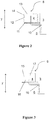
electric apparatus 7 or the total apparatus can be located within thetank 3. As shown inFig.4 , the active parts of the transformer, i.e. the transformer windings and a transformer core, can be located within thetank 3.Fig.4 shows also thetransformer input connections 18 and theload 19 to the transformer. Same reference signs in the Figures refer to corresponding parts in Figures. - Further, the heat generating
electric apparatus 7 may comprise an electric power switch and /or a variable speed drive which can be located within thetank 3, for example. - In yet another embodiment, the means for
heating 5 may be configured to provide heating to theinsulation fluid 4 or the other fluid when the heat generatingelectric apparatus 7 is in a non-operating state. The heating of theinsulation fluid 4 or the other fluid prevents the cooling of theinsulation fluid 4 or the other fluid close to the temperature of the surroundingwater 6 when the heat generatingelectric apparatus 7 is not providing heating to theinsulation fluid 4 or the other fluid in thetank 3. As the temperature decrease remains smaller the contracting movement of thepressure compensator 1 due to the volume reduction of theinsulation fluid 4 or the other fluid remains also smaller. - Another advantage of keeping the
insulation fluid 4 or the other fluid temperature higher than the surroundingwater 6 is that it keeps also the parts of heat generatingelectric apparatus 7 located within thetank 3 at a higher temperature. For instance, the lifetime of a transformer is increased by keeping the hot spot area of the transformer winding drier. - In a further another embodiment, the means for
heating 5 may be configured to gradually close down the heating to theinsulation fluid 4 or the other fluid during the start-up of the heat generatingelectric apparatus 7. - In a still another embodiment, the
subsea installation 2 may comprise means for cooling 20 theinsulation fluid 4 or the other fluid for reducing the volume variations of theinsulation fluid 4 or the other fluid.Fig.5 shows a pressure compensator of a subsea installation comprising means forheating 5 and means for cooling 20. - In an embodiment, the means for cooling 20 is configured to provide cooling when the heat generating
electric apparatus 7 is in an operating state. As the temperature increase remains smaller the expanding movement of thepressure compensator 1 due to the volume increase of theinsulation fluid 4 or the other fluid remains also smaller. - Cooling can be provided through natural or forced convection, for instance.
- The means for cooling may be a
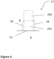
heat pump 21 as shown inFig.6 . The part of theheat pump 22a which is in heat transferring contact with the surroundingwater 6 operates as a condenser and the part of theheat pump 22b which is in heat transferring contact with the insulatingfluid 4 or the other fluid operates as an evaporator. Thus the heat pump transfers heat from the insulatingfluid 4 or the other fluid in thetank 3 to the surroundingwater 6. - The part of the
heat pump 22a which is in heat transferring contact with the surroundingwater 6 may be an external unit heat exchanger outside of thetank 3. The part of theheat pump 22a which is in heat transferring contact with the surroundingwater 6 may also be integrated to anouter wall 23 of thetank 3. An example of the integration is shown inFig.6 where an outer wall of thetank 23 is forming a part of the condenser housing. Surroundingwater 6 freely flows across anouter wall 23 of thetank 3 and cools the working fluid circulating in theheat pump 21 as the heat is dissipated through the outer wall of thetank 23 to the surroundingwater 6. The part of theheat pump 22a forming the condenser is separated from theinsulation fluid 4 with acover 24 which prevents the heat transfer from the condenser to theinsulation fluid 4. Another example of the integration is where the outer surface of the condenser housing may be attached, e.g. connected with thermal grease, to theouter wall 23 of thetank 3. - An advantage of controlling the
insulation fluid 4 or the other fluid temperature increase by providing cooling is that it keeps also the parts of heat generatingelectric apparatus 7 located within thetank 3 at a lower temperature. For instance, the lifetime of a transformer is increased by keeping the temperature rise of the transformer winding within limits. Another advantage of providing cooling to a transformer is that it increases the loading capability of the transformer which is limited mainly by winding temperature. A further advantage of providing cooling to a transformer is the possibility of obtaining a higher power density in a low volume subsea transformer. - In another embodiment, the subsea installation comprises a
temperature sensor 25 for measuring the temperature of theinsulation fluid 4 or the other fluid, and atemperature controller 26 comprising a temperature range. Thetemperature sensor 25 and thetemperature controller 26 are shown inFig.5 only. Thetemperature sensor 25 and thetemperature controller 26 may be installed in any pressure compensator of a subsea installation presented in the Figures. - In yet another embodiment, the temperature range of the
temperature controller 26 is a pre-set range or the temperature range is adjustable by remote control through data transmission. - In a further another embodiment, when the heat generating
electric apparatus 7 is in an operating state the means forheating 5 is configured to provide heating if the measured temperature goes below a set temperature range and the means for cooling 20 are configured to provide cooling if the measured temperature exceeds the set temperature range. - The heat load to the insulating
fluid 4 or the other fluid produced by the heat generatingelectric apparatus 7 depends on the loading 19 of the apparatus. Thus the need of heating or cooling the insulatingfluid 4 or the other fluid in the tank varies when the heat generatingelectric apparatus 7 is in an operating state. - An advantage of controlling the
insulation fluid 4 or the other fluid temperature to remain in a set temperature range is that the volume variations of theinsulation fluid 4 or the other fluid remain in a volume range defined by the temperature variation range. - In a still another embodiment, the means for
heating 5 and the means for cooling 20 is a reversible heat pump working in direction either to provide heating or to provide cooling. - The
heat pump 21 shown inFig.6 may also present a reversible heat pump. In the heating mode the part of theheat pump 22a which is in heat transferring contact with the surroundingwater 6 operates as an evaporator and the part of theheat pump 22b which is in heat transferring contact with the insulatingfluid 4 or the other fluid operates as a condenser. Thus theheat pump 21 transfers heat from the surroundingwater 6 to the insulatingfluid 4 or the other fluid in the tank. - In the cooling mode the part of the
heat pump 22a which is in heat transferring contact with the surroundingwater 6 operates as a condenser and the part of theheat pump 22b which is in heat transferring contact with the insulatingfluid 4 or the other fluid operates as an evaporator. Thus theheat pump 21 transfers heat from the insulatingfluid 4 or the other fluid in thetank 3 to the surroundingwater 6. - In an embodiment, the means for
heating 5 comprises a resistive heater, an inductive heater or a heating cable with an internal temperature control or aheat pump 21. - When the heat pump is used only for heating the insulating
fluid 4 or another fluid the part of theheat pump 22a which is in heat transferring contact with the surroundingwater 6 operates as an evaporator and the part of theheat pump 22b which is in heat transferring contact with the insulatingfluid 4 or the other fluid operates as a condenser. Thus the heat pump transfers heat from the surroundingwater 6 to the insulating fluid or the other fluid in thetank 3. - The required power to the heating or cooling the insulating 4 or the other fluid can be taken with several means, e.g. by separate heating transformer or reactor.
- The inventive subsea installation provides a longer lifetime for the pressure compensator and better reliability, which are key factors for a deep water subsea transformer operation. The inventive subsea installation is advantageous in case the subsea installation has a high heat generation causing large volume variations to the insulating fluid.
- The inventive subsea installation can be applied to different types of subsea assemblies comprising insulation or other fluid in a tank. Examples of such subsea assemblies are subsea motors, subsea switchgears, subsea frequency converters, rectifiers and hydraulic store tanks.
- Part list: 1 a pressure compensator; 2 a subsea installation; 3 a tank; 4 an insulation fluid; 5 means for heating; 6 water; 7 a heat generating apparatus; 8 a bellow compensator; 9 a cylinder compensator;10 a connection pipe; 11 a bottom wall; 12 a bellow; 13 a top wall; 14 side walls; 15 a piston; 16 a fluid space; 17 a sea water space; 18 input connections; 19 a load; 20 means for cooling; 21 a heat pump; 22a-b a part of the heat pump; 23 an outer wall of a tank; 24 a cover; 25 a temperature sensor; 26 a temperature controller; y vertical direction.
Claims (15)
- A subsea installation (2) comprising a tank (3) containing an insulation fluid (4) or other fluid, a heat generating electric apparatus (7) positioned at least partly within the tank (3), and a pressure compensator (1) being in fluid communication with the tank (3) and being configured to compensate volume variations of the insulation fluid (4) or the other fluid by performing an expansive and a contracting movement, characterized in that the subsea installation (2) further comprises means for heating (5) the insulation fluid (4) or the other fluid, said means for heating (5) being configured to provide heating to the insulation fluid (4) or the other fluid when the heat generating electric apparatus (7) is in a non-operating state in order to reduce the volume variations of the insulation fluid (4) or the other fluid.
- A subsea installation according to claim 1, characterized in that the means for heating (5) is configured to gradually close down the heating to the insulation fluid (4) or the other fluid during the start-up of the heat generating electric apparatus (7).
- A subsea installation according to claim 1 or 2, characterized in that the subsea installation (2) comprises means for cooling (20) the insulation fluid (4) or the other fluid for reducing the volume variations of the insulation fluid (4) or the other fluid.
- A subsea installation according to claim 3, characterized in that the means for cooling (20) is configured to provide cooling when the heat generating electric apparatus (7) is in an operating state.
- A subsea installation according to any of claims 1-4, characterized in that the subsea installation (2) comprises a temperature sensor (25) for measuring the temperature of the insulation fluid (4) or the other fluid, and a temperature controller (26) comprising a temperature range.
- A subsea installation according to claim 5, characterized in that the temperature range of the temperature controller (26) is a pre-set range or the temperature range is adjustable by remote control through data transmission.
- A subsea installation according to any of claims 3-6, characterized in that when the heat generating electric apparatus (7) is in an operating state the means for heating (5) is configured to provide heating if the measured temperature goes below the temperature range and the means for cooling (20) are configured to provide cooling if the measured temperature exceeds the temperature range.
- A subsea installation according to claim 7, characterized in that the means for heating (5) and the means for cooling (20) comprises a reversible heat pump (21) working in direction either to provide heating or to provide cooling.
- A subsea installation according to any of claims 3-4, characterized in that the means for cooling (20) comprises a heat pump.
- A subsea installation according to claim 1, characterized in that the means for heating (5) comprises a resistive heater or an inductive heater or a heat pump (21).
- A subsea installation according to claim 1, characterized in that the means for heating (5) comprises a heating cable with an internal temperature control.
- A subsea installation according to any of claims 1-11, characterized in that the heat generating electric apparatus (7) comprises a subsea transformer.
- A subsea installation according to claim 12, characterized in that the insulation fluid (4) is transformer oil.
- A subsea installation according to claim 12, characterized in that transformer windings and a transformer core are located within the tank (3).
- A subsea installation according to any of claims 1-14, characterized in that an electric power switch and/or a variable speed drive are located within the tank (3).
Priority Applications (12)
| Application Number | Priority Date | Filing Date | Title |
|---|---|---|---|
| EP16207075.9A EP3343575B1 (en) | 2016-12-28 | 2016-12-28 | A pressure compensator of a subsea installation |
| DK16207075.9T DK3343575T3 (en) | 2016-12-28 | 2016-12-28 | PRESSURE COMPENSATOR IN AN UNDERWATER INSTALLATION |
| CN201780080788.3A CN110168677B (en) | 2016-12-28 | 2017-12-22 | Subsea equipment |
| NZ754923A NZ754923B (en) | 2016-12-28 | 2017-12-22 | A subsea installation |
| KR1020197022119A KR20190100346A (en) | 2016-12-28 | 2017-12-22 | Pressure compensator for subsea equipment |
| BR112019013343-7A BR112019013343B1 (en) | 2016-12-28 | 2017-12-22 | SUBMARINE INSTALLATION |
| JP2019535253A JP2020504448A (en) | 2016-12-28 | 2017-12-22 | Underwater equipment pressure compensator |
| AU2017390076A AU2017390076B2 (en) | 2016-12-28 | 2017-12-22 | A pressure compensator of a subsea installation |
| MX2019007712A MX2019007712A (en) | 2016-12-28 | 2017-12-22 | A pressure compensator of a subsea installation. |
| PCT/EP2017/084319 WO2018122152A1 (en) | 2016-12-28 | 2017-12-22 | A pressure compensator of a subsea installation |
| US16/454,530 US11212931B2 (en) | 2016-12-28 | 2019-06-27 | Subsea installation |
| JP2021001331U JP3234650U (en) | 2016-12-28 | 2021-04-12 | Underwater equipment |
Applications Claiming Priority (1)
| Application Number | Priority Date | Filing Date | Title |
|---|---|---|---|
| EP16207075.9A EP3343575B1 (en) | 2016-12-28 | 2016-12-28 | A pressure compensator of a subsea installation |
Publications (2)
| Publication Number | Publication Date |
|---|---|
| EP3343575A1 EP3343575A1 (en) | 2018-07-04 |
| EP3343575B1 true EP3343575B1 (en) | 2020-03-18 |
Family
ID=57749751
Family Applications (1)
| Application Number | Title | Priority Date | Filing Date |
|---|---|---|---|
| EP16207075.9A Active EP3343575B1 (en) | 2016-12-28 | 2016-12-28 | A pressure compensator of a subsea installation |
Country Status (9)
| Country | Link |
|---|---|
| US (1) | US11212931B2 (en) |
| EP (1) | EP3343575B1 (en) |
| JP (2) | JP2020504448A (en) |
| KR (1) | KR20190100346A (en) |
| CN (1) | CN110168677B (en) |
| AU (1) | AU2017390076B2 (en) |
| DK (1) | DK3343575T3 (en) |
| MX (1) | MX2019007712A (en) |
| WO (1) | WO2018122152A1 (en) |
Families Citing this family (4)
| Publication number | Priority date | Publication date | Assignee | Title |
|---|---|---|---|---|
| CN110290663A (en) * | 2019-06-20 | 2019-09-27 | 深圳市洛丁光电有限公司 | A kind of water proof type communication electric component box |
| CN110534293A (en) * | 2019-09-20 | 2019-12-03 | 徐州科奥电气有限公司 | A kind of fault-tolerant underwater transformer |
| NO346035B1 (en) * | 2019-10-02 | 2022-01-10 | Fmc Kongsberg Subsea As | Pressure compensator and assembly comprising a subsea installation and such a pressure compensator |
| JP7808240B1 (en) | 2023-02-03 | 2026-01-28 | ヒタチ・エナジー・リミテッド | Systems that include transformers |
Family Cites Families (53)
| Publication number | Priority date | Publication date | Assignee | Title |
|---|---|---|---|---|
| US2800612A (en) * | 1954-05-05 | 1957-07-23 | Taylor Winfield Corp | Control system for the protection of welding transformers |
| US3142029A (en) * | 1960-08-22 | 1964-07-21 | Gen Electric | Shielding of foil wound electrical apparatus |
| US3264589A (en) * | 1963-09-03 | 1966-08-02 | Gen Electric | Transformer pockets for vaporized cooling |
| JPS5710214A (en) * | 1980-06-23 | 1982-01-19 | Fuji Electric Co Ltd | Underwater electric device |
| DE3025661C2 (en) * | 1980-07-07 | 1982-11-04 | Transformatoren Union Ag, 7000 Stuttgart | Device for utilizing the heat loss from internally liquid-cooled transformers or inductors |
| JPS57119515U (en) * | 1981-01-16 | 1982-07-24 | ||
| JPS58202512A (en) * | 1982-05-21 | 1983-11-25 | Mitsubishi Electric Corp | Gas-insulated electrical apparatus |
| DE69021966T2 (en) * | 1989-07-10 | 1996-04-18 | Hitachi Ltd | Electrical machine immersed in insulating liquid. |
| JP2766574B2 (en) * | 1992-01-07 | 1998-06-18 | 三菱電機株式会社 | Oil inlet abnormality monitoring device |
| JPH07167526A (en) | 1993-12-14 | 1995-07-04 | Shikoku Sogo Kenkyusho:Kk | Heater/cooler for liquid |
| SE0001673L (en) * | 2000-05-08 | 2001-09-17 | Kjell Andersson | Plant for disposing of excess heat from a power transformer |
| NO313068B1 (en) * | 2000-11-14 | 2002-08-05 | Abb As | Underwater transformer - distribution system with a first and a second chamber |
| US7220365B2 (en) * | 2001-08-13 | 2007-05-22 | New Qu Energy Ltd. | Devices using a medium having a high heat transfer rate |
| US6842718B2 (en) * | 2003-02-06 | 2005-01-11 | General Electric Company | Intelligent auxiliary cooling system |
| US7223941B2 (en) * | 2003-02-08 | 2007-05-29 | Walker Ip And Business Enterprises, Llc | Reduced-volume commercial space heating system and method for manufacturing same |
| US8203411B2 (en) * | 2004-06-17 | 2012-06-19 | Maclennan Grant A | Potted inductor apparatus and method of use thereof |
| US8519813B2 (en) * | 2004-06-17 | 2013-08-27 | Grant A. MacLennan | Liquid cooled inductor apparatus and method of use thereof |
| GB2439026B (en) * | 2005-04-05 | 2009-10-28 | Vetco Gray Scandinavia As | An arrangement for heat transport or cooling |
| EP1911050B1 (en) * | 2005-07-01 | 2015-06-17 | Siemens Aktiengesellschaft | Transformer with electrical switch |
| NO324576B1 (en) * | 2005-11-11 | 2007-11-26 | Norsk Hydro Produksjon As | Underwater Transformer Arrangement |
| US7931090B2 (en) * | 2005-11-15 | 2011-04-26 | Schlumberger Technology Corporation | System and method for controlling subsea wells |
| WO2008035194A2 (en) * | 2006-09-21 | 2008-03-27 | Vetco Gray Scandinavia As | A method and an apparatus for cold start of a subsea production system |
| BRPI0703726B1 (en) * | 2007-10-10 | 2018-06-12 | Petróleo Brasileiro S.A. - Petrobras | PUMP MODULE AND SYSTEM FOR SUBMARINE HYDROCARBON PRODUCTS WITH HIGH FRACTION ASSOCIATED GAS |
| PL2104116T3 (en) * | 2008-03-12 | 2017-09-29 | Alstom Transport Technologies | Oil cooling system, particularly for transformers feeding traction electric motors, transformer with said system and method for determining the cooling fluid flow in a cooling system |
| AU2009282170B2 (en) * | 2008-08-11 | 2014-11-27 | Green Revolution Cooling, Inc. | Liquid submerged, horizontal computer server rack and systems and methods of cooling such a server rack |
| EP2169690B1 (en) * | 2008-09-24 | 2012-08-29 | ABB Technology AG | Pressure compensator |
| TR200900450A2 (en) * | 2009-01-22 | 2009-11-23 | �Uhaci �Brah�M | Thermochemical Thermodynamic Recycling Machine |
| ES2437750T3 (en) * | 2009-11-17 | 2014-01-14 | Abb Research Ltd | Electric transformer with diaphragm and cooling method |
| WO2011067290A1 (en) * | 2009-12-01 | 2011-06-09 | Vestas Wind Systems A/S | A wind turbine nacelle comprising a heat exchanger assembly |
| EP2431985A1 (en) * | 2010-09-16 | 2012-03-21 | Starkstrom-Gerätebau GmbH | Integrated cooling system |
| EP2511919A1 (en) * | 2011-04-11 | 2012-10-17 | ABB Technology AG | Dry transformer heating |
| US8405991B2 (en) | 2011-05-20 | 2013-03-26 | General Electric Company | Heat transfer element temperature variation system |
| WO2013007697A1 (en) * | 2011-07-08 | 2013-01-17 | Abb Research Ltd | Gas-insulated delta transformer |
| ES2679821T3 (en) * | 2011-07-18 | 2018-08-31 | Abb Schweiz Ag | Dry transformer |
| EP2571034A1 (en) * | 2011-09-19 | 2013-03-20 | Siemens Aktiengesellschaft | Subsea transformer enclosure |
| EP2590185B1 (en) * | 2011-11-02 | 2014-04-02 | ABB Technology AG | High voltage transformer module |
| ES2453979T3 (en) * | 2011-12-08 | 2014-04-09 | Abb Technology Ag | Oil transformer |
| ES2841987T3 (en) * | 2012-01-18 | 2021-07-12 | Abb Power Grids Switzerland Ag | Transformer core |
| EP2810134B1 (en) * | 2012-02-01 | 2016-06-01 | ABB Research Ltd. | Monitoring of primary devices in a power system |
| US9435819B1 (en) * | 2012-04-27 | 2016-09-06 | Cree Fayetteville, Inc. | Autonomous temperature accelerometer sensor |
| US20130286591A1 (en) * | 2012-04-30 | 2013-10-31 | General Electric Company | Power Electronics Cooling |
| US8928443B2 (en) * | 2012-05-17 | 2015-01-06 | Elwha Llc | Electrical device with emergency cooling system |
| EP2738780B1 (en) * | 2012-11-28 | 2016-03-16 | ABB Technology AG | Subsea pressure compensation arrangement |
| US20140307384A1 (en) * | 2013-04-11 | 2014-10-16 | Green Revolution Cooling, Inc. | Integrated computing module with power and liquid cooling components |
| NO337146B1 (en) * | 2013-06-24 | 2016-02-01 | Fmc Kongsberg Subsea As | Subsea system and method for filtration and treatment of seawater. |
| NO337246B1 (en) * | 2014-06-11 | 2016-02-22 | Fmc Kongsberg Subsea As | Underwater cooling assembly |
| DK2988311T3 (en) * | 2014-08-22 | 2021-07-26 | Abb Schweiz Ag | Pressure compensated subsea electrical system |
| EP3048619B1 (en) * | 2015-01-23 | 2017-05-17 | Siemens Aktiengesellschaft | Pressure compensator for subsea device |
| US10026537B2 (en) * | 2015-02-25 | 2018-07-17 | Onesubsea Ip Uk Limited | Fault tolerant subsea transformer |
| WO2016144805A1 (en) * | 2015-03-06 | 2016-09-15 | Oceaneering International, Inc. | Subsea rov-mounted hot water injection skid |
| US20170005468A1 (en) * | 2015-06-30 | 2017-01-05 | General Electric Company | Power supply and distribution system and an associated method thereof |
| BE1024914B1 (en) * | 2017-01-16 | 2018-08-16 | Minnoy Bvba | A HEATING SYSTEM AND A HEATING METHOD |
| EP3397034B1 (en) * | 2017-04-26 | 2019-12-04 | ABB Schweiz AG | Subsea arrangement and method for detecting a malfunction of a subsea arrangement |
-
2016
- 2016-12-28 EP EP16207075.9A patent/EP3343575B1/en active Active
- 2016-12-28 DK DK16207075.9T patent/DK3343575T3/en active
-
2017
- 2017-12-22 WO PCT/EP2017/084319 patent/WO2018122152A1/en not_active Ceased
- 2017-12-22 JP JP2019535253A patent/JP2020504448A/en active Pending
- 2017-12-22 AU AU2017390076A patent/AU2017390076B2/en active Active
- 2017-12-22 CN CN201780080788.3A patent/CN110168677B/en active Active
- 2017-12-22 KR KR1020197022119A patent/KR20190100346A/en not_active Ceased
- 2017-12-22 MX MX2019007712A patent/MX2019007712A/en unknown
-
2019
- 2019-06-27 US US16/454,530 patent/US11212931B2/en active Active
-
2021
- 2021-04-12 JP JP2021001331U patent/JP3234650U/en active Active
Non-Patent Citations (1)
| Title |
|---|
| None * |
Also Published As
| Publication number | Publication date |
|---|---|
| US20190320545A1 (en) | 2019-10-17 |
| JP2020504448A (en) | 2020-02-06 |
| KR20190100346A (en) | 2019-08-28 |
| NZ754923A (en) | 2020-03-27 |
| CN110168677A (en) | 2019-08-23 |
| MX2019007712A (en) | 2019-09-09 |
| JP3234650U (en) | 2021-10-28 |
| WO2018122152A1 (en) | 2018-07-05 |
| DK3343575T3 (en) | 2020-06-22 |
| AU2017390076B2 (en) | 2020-06-11 |
| US11212931B2 (en) | 2021-12-28 |
| EP3343575A1 (en) | 2018-07-04 |
| CN110168677B (en) | 2021-11-02 |
| AU2017390076A1 (en) | 2019-07-11 |
| BR112019013343A2 (en) | 2019-12-24 |
Similar Documents
| Publication | Publication Date | Title |
|---|---|---|
| US11212931B2 (en) | Subsea installation | |
| RU2680722C2 (en) | Pressure compensated subsea electrical system | |
| RU2693035C1 (en) | Transformer with temperature-dependent cooling | |
| EP2169691B1 (en) | Pressure compensator | |
| EP2738780B1 (en) | Subsea pressure compensation arrangement | |
| AU2010231128B2 (en) | Power unit | |
| EP3404198B1 (en) | A cooling arrangement of a subsea installation | |
| EP2679765B1 (en) | Subsea unit comprising a two-phase cooling system | |
| EP2988579A1 (en) | Oil cooling configuration for an electronic subsea system | |
| EP2919571A1 (en) | Arrangement for subsea cooling of electric equipment | |
| NZ754923B (en) | A subsea installation | |
| EP4038257B1 (en) | Pressure compensator and assembly comprising a subsea installation and such a pressure compensator | |
| BR112019013343B1 (en) | SUBMARINE INSTALLATION | |
| CN206558320U (en) | Ripple compensation radiator | |
| DK2733265T3 (en) | Cooling system for a transformer platform | |
| EP3211980A1 (en) | Arrangement for subsea cooling of power electronic cells | |
| JPH0786049A (en) | Stationary induction |
Legal Events
| Date | Code | Title | Description |
|---|---|---|---|
| PUAI | Public reference made under article 153(3) epc to a published international application that has entered the european phase |
Free format text: ORIGINAL CODE: 0009012 |
|
| STAA | Information on the status of an ep patent application or granted ep patent |
Free format text: STATUS: THE APPLICATION HAS BEEN PUBLISHED |
|
| AK | Designated contracting states |
Kind code of ref document: A1 Designated state(s): AL AT BE BG CH CY CZ DE DK EE ES FI FR GB GR HR HU IE IS IT LI LT LU LV MC MK MT NL NO PL PT RO RS SE SI SK SM TR |
|
| AX | Request for extension of the european patent |
Extension state: BA ME |
|
| STAA | Information on the status of an ep patent application or granted ep patent |
Free format text: STATUS: REQUEST FOR EXAMINATION WAS MADE |
|
| 17P | Request for examination filed |
Effective date: 20180907 |
|
| RBV | Designated contracting states (corrected) |
Designated state(s): AL AT BE BG CH CY CZ DE DK EE ES FI FR GB GR HR HU IE IS IT LI LT LU LV MC MK MT NL NO PL PT RO RS SE SI SK SM TR |
|
| STAA | Information on the status of an ep patent application or granted ep patent |
Free format text: STATUS: EXAMINATION IS IN PROGRESS |
|
| 17Q | First examination report despatched |
Effective date: 20190102 |
|
| GRAP | Despatch of communication of intention to grant a patent |
Free format text: ORIGINAL CODE: EPIDOSNIGR1 |
|
| STAA | Information on the status of an ep patent application or granted ep patent |
Free format text: STATUS: GRANT OF PATENT IS INTENDED |
|
| INTG | Intention to grant announced |
Effective date: 20191015 |
|
| GRAS | Grant fee paid |
Free format text: ORIGINAL CODE: EPIDOSNIGR3 |
|
| GRAJ | Information related to disapproval of communication of intention to grant by the applicant or resumption of examination proceedings by the epo deleted |
Free format text: ORIGINAL CODE: EPIDOSDIGR1 |
|
| GRAL | Information related to payment of fee for publishing/printing deleted |
Free format text: ORIGINAL CODE: EPIDOSDIGR3 |
|
| STAA | Information on the status of an ep patent application or granted ep patent |
Free format text: STATUS: EXAMINATION IS IN PROGRESS |
|
| GRAR | Information related to intention to grant a patent recorded |
Free format text: ORIGINAL CODE: EPIDOSNIGR71 |
|
| STAA | Information on the status of an ep patent application or granted ep patent |
Free format text: STATUS: GRANT OF PATENT IS INTENDED |
|
| GRAA | (expected) grant |
Free format text: ORIGINAL CODE: 0009210 |
|
| STAA | Information on the status of an ep patent application or granted ep patent |
Free format text: STATUS: THE PATENT HAS BEEN GRANTED |
|
| INTC | Intention to grant announced (deleted) | ||
| AK | Designated contracting states |
Kind code of ref document: B1 Designated state(s): AL AT BE BG CH CY CZ DE DK EE ES FI FR GB GR HR HU IE IS IT LI LT LU LV MC MK MT NL NO PL PT RO RS SE SI SK SM TR |
|
| INTG | Intention to grant announced |
Effective date: 20200207 |
|
| REG | Reference to a national code |
Ref country code: GB Ref legal event code: FG4D |
|
| REG | Reference to a national code |
Ref country code: DE Ref legal event code: R096 Ref document number: 602016031946 Country of ref document: DE |
|
| REG | Reference to a national code |
Ref country code: AT Ref legal event code: REF Ref document number: 1246865 Country of ref document: AT Kind code of ref document: T Effective date: 20200415 Ref country code: IE Ref legal event code: FG4D |
|
| REG | Reference to a national code |
Ref country code: FI Ref legal event code: FGE |
|
| REG | Reference to a national code |
Ref country code: DK Ref legal event code: T3 Effective date: 20200615 Ref country code: NO Ref legal event code: T2 Effective date: 20200318 |
|
| PG25 | Lapsed in a contracting state [announced via postgrant information from national office to epo] |
Ref country code: RS Free format text: LAPSE BECAUSE OF FAILURE TO SUBMIT A TRANSLATION OF THE DESCRIPTION OR TO PAY THE FEE WITHIN THE PRESCRIBED TIME-LIMIT Effective date: 20200318 |
|
| REG | Reference to a national code |
Ref country code: NL Ref legal event code: MP Effective date: 20200318 |
|
| PG25 | Lapsed in a contracting state [announced via postgrant information from national office to epo] |
Ref country code: BG Free format text: LAPSE BECAUSE OF FAILURE TO SUBMIT A TRANSLATION OF THE DESCRIPTION OR TO PAY THE FEE WITHIN THE PRESCRIBED TIME-LIMIT Effective date: 20200618 Ref country code: SE Free format text: LAPSE BECAUSE OF FAILURE TO SUBMIT A TRANSLATION OF THE DESCRIPTION OR TO PAY THE FEE WITHIN THE PRESCRIBED TIME-LIMIT Effective date: 20200318 Ref country code: LV Free format text: LAPSE BECAUSE OF FAILURE TO SUBMIT A TRANSLATION OF THE DESCRIPTION OR TO PAY THE FEE WITHIN THE PRESCRIBED TIME-LIMIT Effective date: 20200318 Ref country code: HR Free format text: LAPSE BECAUSE OF FAILURE TO SUBMIT A TRANSLATION OF THE DESCRIPTION OR TO PAY THE FEE WITHIN THE PRESCRIBED TIME-LIMIT Effective date: 20200318 Ref country code: GR Free format text: LAPSE BECAUSE OF FAILURE TO SUBMIT A TRANSLATION OF THE DESCRIPTION OR TO PAY THE FEE WITHIN THE PRESCRIBED TIME-LIMIT Effective date: 20200619 |
|
| REG | Reference to a national code |
Ref country code: LT Ref legal event code: MG4D |
|
| PG25 | Lapsed in a contracting state [announced via postgrant information from national office to epo] |
Ref country code: NL Free format text: LAPSE BECAUSE OF FAILURE TO SUBMIT A TRANSLATION OF THE DESCRIPTION OR TO PAY THE FEE WITHIN THE PRESCRIBED TIME-LIMIT Effective date: 20200318 |
|
| PG25 | Lapsed in a contracting state [announced via postgrant information from national office to epo] |
Ref country code: SK Free format text: LAPSE BECAUSE OF FAILURE TO SUBMIT A TRANSLATION OF THE DESCRIPTION OR TO PAY THE FEE WITHIN THE PRESCRIBED TIME-LIMIT Effective date: 20200318 Ref country code: IS Free format text: LAPSE BECAUSE OF FAILURE TO SUBMIT A TRANSLATION OF THE DESCRIPTION OR TO PAY THE FEE WITHIN THE PRESCRIBED TIME-LIMIT Effective date: 20200718 Ref country code: LT Free format text: LAPSE BECAUSE OF FAILURE TO SUBMIT A TRANSLATION OF THE DESCRIPTION OR TO PAY THE FEE WITHIN THE PRESCRIBED TIME-LIMIT Effective date: 20200318 Ref country code: EE Free format text: LAPSE BECAUSE OF FAILURE TO SUBMIT A TRANSLATION OF THE DESCRIPTION OR TO PAY THE FEE WITHIN THE PRESCRIBED TIME-LIMIT Effective date: 20200318 Ref country code: SM Free format text: LAPSE BECAUSE OF FAILURE TO SUBMIT A TRANSLATION OF THE DESCRIPTION OR TO PAY THE FEE WITHIN THE PRESCRIBED TIME-LIMIT Effective date: 20200318 Ref country code: CZ Free format text: LAPSE BECAUSE OF FAILURE TO SUBMIT A TRANSLATION OF THE DESCRIPTION OR TO PAY THE FEE WITHIN THE PRESCRIBED TIME-LIMIT Effective date: 20200318 Ref country code: PT Free format text: LAPSE BECAUSE OF FAILURE TO SUBMIT A TRANSLATION OF THE DESCRIPTION OR TO PAY THE FEE WITHIN THE PRESCRIBED TIME-LIMIT Effective date: 20200812 Ref country code: RO Free format text: LAPSE BECAUSE OF FAILURE TO SUBMIT A TRANSLATION OF THE DESCRIPTION OR TO PAY THE FEE WITHIN THE PRESCRIBED TIME-LIMIT Effective date: 20200318 |
|
| REG | Reference to a national code |
Ref country code: AT Ref legal event code: MK05 Ref document number: 1246865 Country of ref document: AT Kind code of ref document: T Effective date: 20200318 |
|
| REG | Reference to a national code |
Ref country code: DE Ref legal event code: R097 Ref document number: 602016031946 Country of ref document: DE |
|
| PLBE | No opposition filed within time limit |
Free format text: ORIGINAL CODE: 0009261 |
|
| STAA | Information on the status of an ep patent application or granted ep patent |
Free format text: STATUS: NO OPPOSITION FILED WITHIN TIME LIMIT |
|
| PG25 | Lapsed in a contracting state [announced via postgrant information from national office to epo] |
Ref country code: IT Free format text: LAPSE BECAUSE OF FAILURE TO SUBMIT A TRANSLATION OF THE DESCRIPTION OR TO PAY THE FEE WITHIN THE PRESCRIBED TIME-LIMIT Effective date: 20200318 Ref country code: ES Free format text: LAPSE BECAUSE OF FAILURE TO SUBMIT A TRANSLATION OF THE DESCRIPTION OR TO PAY THE FEE WITHIN THE PRESCRIBED TIME-LIMIT Effective date: 20200318 Ref country code: AT Free format text: LAPSE BECAUSE OF FAILURE TO SUBMIT A TRANSLATION OF THE DESCRIPTION OR TO PAY THE FEE WITHIN THE PRESCRIBED TIME-LIMIT Effective date: 20200318 |
|
| 26N | No opposition filed |
Effective date: 20201221 |
|
| PG25 | Lapsed in a contracting state [announced via postgrant information from national office to epo] |
Ref country code: PL Free format text: LAPSE BECAUSE OF FAILURE TO SUBMIT A TRANSLATION OF THE DESCRIPTION OR TO PAY THE FEE WITHIN THE PRESCRIBED TIME-LIMIT Effective date: 20200318 |
|
| PG25 | Lapsed in a contracting state [announced via postgrant information from national office to epo] |
Ref country code: SI Free format text: LAPSE BECAUSE OF FAILURE TO SUBMIT A TRANSLATION OF THE DESCRIPTION OR TO PAY THE FEE WITHIN THE PRESCRIBED TIME-LIMIT Effective date: 20200318 |
|
| REG | Reference to a national code |
Ref country code: CH Ref legal event code: PL |
|
| PG25 | Lapsed in a contracting state [announced via postgrant information from national office to epo] |
Ref country code: MC Free format text: LAPSE BECAUSE OF FAILURE TO SUBMIT A TRANSLATION OF THE DESCRIPTION OR TO PAY THE FEE WITHIN THE PRESCRIBED TIME-LIMIT Effective date: 20200318 |
|
| REG | Reference to a national code |
Ref country code: BE Ref legal event code: MM Effective date: 20201231 |
|
| PG25 | Lapsed in a contracting state [announced via postgrant information from national office to epo] |
Ref country code: IE Free format text: LAPSE BECAUSE OF NON-PAYMENT OF DUE FEES Effective date: 20201228 Ref country code: LU Free format text: LAPSE BECAUSE OF NON-PAYMENT OF DUE FEES Effective date: 20201228 |
|
| PG25 | Lapsed in a contracting state [announced via postgrant information from national office to epo] |
Ref country code: CH Free format text: LAPSE BECAUSE OF NON-PAYMENT OF DUE FEES Effective date: 20201231 Ref country code: LI Free format text: LAPSE BECAUSE OF NON-PAYMENT OF DUE FEES Effective date: 20201231 |
|
| PG25 | Lapsed in a contracting state [announced via postgrant information from national office to epo] |
Ref country code: TR Free format text: LAPSE BECAUSE OF FAILURE TO SUBMIT A TRANSLATION OF THE DESCRIPTION OR TO PAY THE FEE WITHIN THE PRESCRIBED TIME-LIMIT Effective date: 20200318 Ref country code: MT Free format text: LAPSE BECAUSE OF FAILURE TO SUBMIT A TRANSLATION OF THE DESCRIPTION OR TO PAY THE FEE WITHIN THE PRESCRIBED TIME-LIMIT Effective date: 20200318 Ref country code: CY Free format text: LAPSE BECAUSE OF FAILURE TO SUBMIT A TRANSLATION OF THE DESCRIPTION OR TO PAY THE FEE WITHIN THE PRESCRIBED TIME-LIMIT Effective date: 20200318 |
|
| PG25 | Lapsed in a contracting state [announced via postgrant information from national office to epo] |
Ref country code: MK Free format text: LAPSE BECAUSE OF FAILURE TO SUBMIT A TRANSLATION OF THE DESCRIPTION OR TO PAY THE FEE WITHIN THE PRESCRIBED TIME-LIMIT Effective date: 20200318 Ref country code: AL Free format text: LAPSE BECAUSE OF FAILURE TO SUBMIT A TRANSLATION OF THE DESCRIPTION OR TO PAY THE FEE WITHIN THE PRESCRIBED TIME-LIMIT Effective date: 20200318 |
|
| PG25 | Lapsed in a contracting state [announced via postgrant information from national office to epo] |
Ref country code: BE Free format text: LAPSE BECAUSE OF NON-PAYMENT OF DUE FEES Effective date: 20201231 |
|
| PGFP | Annual fee paid to national office [announced via postgrant information from national office to epo] |
Ref country code: DE Payment date: 20251211 Year of fee payment: 10 |
|
| PGFP | Annual fee paid to national office [announced via postgrant information from national office to epo] |
Ref country code: GB Payment date: 20251219 Year of fee payment: 10 |
|
| PGFP | Annual fee paid to national office [announced via postgrant information from national office to epo] |
Ref country code: FI Payment date: 20251223 Year of fee payment: 10 Ref country code: DK Payment date: 20251224 Year of fee payment: 10 |
|
| PGFP | Annual fee paid to national office [announced via postgrant information from national office to epo] |
Ref country code: FR Payment date: 20251229 Year of fee payment: 10 |
|
| PGFP | Annual fee paid to national office [announced via postgrant information from national office to epo] |
Ref country code: NO Payment date: 20251230 Year of fee payment: 10 |