EP3343239A1 - Differenzstromüberwachung mehrerer schaltkreise - Google Patents
Differenzstromüberwachung mehrerer schaltkreise Download PDFInfo
- Publication number
- EP3343239A1 EP3343239A1 EP17210755.9A EP17210755A EP3343239A1 EP 3343239 A1 EP3343239 A1 EP 3343239A1 EP 17210755 A EP17210755 A EP 17210755A EP 3343239 A1 EP3343239 A1 EP 3343239A1
- Authority
- EP
- European Patent Office
- Prior art keywords
- nodes
- pulse
- control module
- issuing
- node
- Prior art date
- Legal status (The legal status is an assumption and is not a legal conclusion. Google has not performed a legal analysis and makes no representation as to the accuracy of the status listed.)
- Granted
Links
Images

Classifications
-
- G—PHYSICS
- G01—MEASURING; TESTING
- G01R—MEASURING ELECTRIC VARIABLES; MEASURING MAGNETIC VARIABLES
- G01R31/00—Arrangements for testing electric properties; Arrangements for locating electric faults; Arrangements for electrical testing characterised by what is being tested not provided for elsewhere
- G01R31/50—Testing of electric apparatus, lines, cables or components for short-circuits, continuity, leakage current or incorrect line connections
-
- G—PHYSICS
- G06—COMPUTING OR CALCULATING; COUNTING
- G06F—ELECTRIC DIGITAL DATA PROCESSING
- G06F1/00—Details not covered by groups G06F3/00 - G06F13/00 and G06F21/00
- G06F1/26—Power supply means, e.g. regulation thereof
- G06F1/30—Means for acting in the event of power-supply failure or interruption, e.g. power-supply fluctuations
- G06F1/305—Means for acting in the event of power-supply failure or interruption, e.g. power-supply fluctuations in the event of power-supply fluctuations
-
- G—PHYSICS
- G06—COMPUTING OR CALCULATING; COUNTING
- G06F—ELECTRIC DIGITAL DATA PROCESSING
- G06F1/00—Details not covered by groups G06F3/00 - G06F13/00 and G06F21/00
- G06F1/26—Power supply means, e.g. regulation thereof
- G06F1/32—Means for saving power
- G06F1/3203—Power management, i.e. event-based initiation of a power-saving mode
- G06F1/3206—Monitoring of events, devices or parameters that trigger a change in power modality
-
- G—PHYSICS
- G01—MEASURING; TESTING
- G01R—MEASURING ELECTRIC VARIABLES; MEASURING MAGNETIC VARIABLES
- G01R19/00—Arrangements for measuring currents or voltages or for indicating presence or sign thereof
- G01R19/0092—Measuring current only
-
- H—ELECTRICITY
- H02—GENERATION; CONVERSION OR DISTRIBUTION OF ELECTRIC POWER
- H02H—EMERGENCY PROTECTIVE CIRCUIT ARRANGEMENTS
- H02H1/00—Details of emergency protective circuit arrangements
- H02H1/0061—Details of emergency protective circuit arrangements concerning transmission of signals
-
- H—ELECTRICITY
- H02—GENERATION; CONVERSION OR DISTRIBUTION OF ELECTRIC POWER
- H02H—EMERGENCY PROTECTIVE CIRCUIT ARRANGEMENTS
- H02H7/00—Emergency protective circuit arrangements specially adapted for specific types of electric machines or apparatus or for sectionalised protection of cable or line systems, and effecting automatic switching in the event of an undesired change from normal working conditions
- H02H7/26—Sectionalised protection of cable or line systems, e.g. for disconnecting a section on which a short-circuit, earth fault, or arc discharge has occured
- H02H7/261—Sectionalised protection of cable or line systems, e.g. for disconnecting a section on which a short-circuit, earth fault, or arc discharge has occured involving signal transmission between at least two stations
Definitions
- the present disclosure relates to current protection, and more particularly to differential current monitoring for current protection.
- a system for differential current monitoring includes a control module and a plurality of nodes operatively connected to the control module. Each node is configured to monitor current from a bus to a respective load.
- the control module and nodes are configured to monitor current at each of the nodes, issue a pulse for each node, wherein the pulse has a duration that is proportional to current at (or through) the node, concatenate all of the pulses for the nodes to determine the total current drawn from the bus at the nodes, compare the total current drawn from the bus at the nodes to current input to the bus, and signal a fault condition if the total current drawn from the bus is not within a predetermined range of the current input to the bus.
- the nodes can be arranged in a daisy chain and wherein issuing a pulse for each node includes sequentially issuing a pulse from one node to another along the daisy chain to create a pulse train, wherein each node in the daisy chain adds its pulse duration cumulatively to the total time to the end of the pulse train.
- the control module can be directly connected to a first one of the nodes and wherein issuing a pulse for each node includes issuing an initial pulse from a control module to the first one of the nodes to initiate transmission of the pulse train along the daisy chain.
- the control module can be directly connected to a final one of the nodes, wherein issuing a pulse for each node includes transmitting the pulse train back from a final one of the nodes in the daisy chain to the control module.
- the control module can be directly connected to each of the nodes, wherein the control module and nodes are configured to simultaneously issue a start pulse from a control module to each of the nodes so that all nodes sample their respective currents at the same time.
- a method of differential current monitoring includes monitoring current at each of a plurality of nodes where loads are powered from a bus, issuing a pulse for each node, wherein the pulse has a duration that is proportional to current at the node, concatenating all of the pulses for the nodes to determine the total current drawn from the bus at the nodes, comparing the total current drawn from the bus at the nodes to current input to the bus, and signaling a fault condition if the total current drawn from the bus is not within a predetermined range of the current input to the bus.
- Summing all of the pulses can include measuring duration of round trip time from the first pulse out of the control module until the end of the very last pulse back to the control module, wherein the duration of round trip time is proportional to the sum of all the current through the nodes.
- the method can include monitoring for a timeout condition in the control module in response to failure to receive the pulse train from the last one of the nodes in the daisy chain, and reporting a fault in response to the timeout condition.
- Each of the nodes can use a common time/current scale factor for issuing the respective pulse, so the number of nodes can be adjusted.
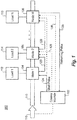
- Fig. 1 a partial view of an exemplary embodiment of a system in accordance with the disclosure is shown in Fig. 1 and is designated generally by reference character 100.
- Fig. 2 Other embodiments of systems in accordance with the disclosure, or aspects thereof, are provided in Fig. 2 , as will be described.
- the systems and methods described herein can be used for differential current monitoring, for example in high power and/or solid state systems.
- System 100 for differential current monitoring includes a control module 102 and a plurality of nodes 104, 106, and 108 operatively connected to the control module 102.
- Each node 104, 106, and 108 is configured to monitor current from a bus 110 to a respective load 112, 114, and 116.
- the ellipsis in Fig. 1 indicate any suitable number of nodes and respective loads can be included without departing from the scope of this disclosure.
- the control module 102 and nodes 104, 106, and 108 are configured to monitor current at each of the nodes 104, 106, and 108 and issue a pulse for each node 104, 106, and 108 (the control module 102 need only directly monitor the current at input 118 of bus 110 and need have no direct bearing on the measurement of current at the nodes 104, 106, and 108).
- the pulse from each node has a pulse duration that is proportional to current measured or monitored at the node 104, 106, and 108.
- Control module 102 can sum all of the pulses, e.g. pulse durations, for the nodes 104, 106, and 108 to determine the total current drawn from the bus 110 at the nodes 104, 106, and 108.
- the concatenation of the pulses is what performs the sum.
- the control module can simply measure the resulting pulse duration from end to end and compares to the current 118. In other words the summation can be the inherent result of the daisy chain of the pulses as further explained below.
- Control module 102 is connected to the input 118 of bus 110 so control module 102 can compare the total current drawn from the bus 110 at the nodes 104, 106, and 108 to the current input to the bus 110. If the total current drawn from the bus 110 is not within a predetermined range of the current input to the bus 110, control module 102 can signal a fault condition, such as a ground mode fault.
- the nodes 104, 106, and 108 are arranged in a daisy chain 120. Issuing a pulse for each node 104, 106, and 108 can include sequentially issuing a pulse from one node to another along the daisy chain 120 to create a pulse train 122 shown in Fig. 2 and described below, wherein each node 104, 106, and 108 in the daisy chain 120 adds its pulse duration cumulatively to the total time to the end of the pulse train 122. Summing all of the pulses can include measuring duration of round trip time from the first pulse out of the control module 102 until the end of the very last pulse back to the control module 102 from node 108. The duration of round trip time is proportional to the sum of all the current through the nodes 104, 106, and 108.
- the control module 102 is directly connected to a first one of the nodes 104 at line 124. Issuing a pulse for each node 104, 106, and 108 can include issuing an initial pulse from control module 102 to the first one of the nodes 104 to initiate transmission of the pulse train 122 along the daisy chain 120.
- the control module 102 is directly connected to a final one of the nodes 108 at line 126, wherein issuing a pulse for each node 104, 106, and 108 includes transmitting the pulse train 122 back from the final one of the nodes 108 in the daisy chain 120 to the control module 102.
- the control module 102 can optionally be directly connected to each of the nodes 104, 106, and 108, e.g., using the dashed extensions of line lines 124 in Fig. 1 , or using dedicated lines 128 and 130.
- the control module 102 and nodes 104, 106, and 108 can be configured to simultaneously issue a start pulse from the control module 102 to each of the nodes 104, 106, and 108 so that all nodes 104, 106, and 108 sample their respective currents at the same time.
- the nodes 106 and 108 delay issuing their pulses until the node 104 transmits is pulse to node 106, which transmits its pulse and so on along the daisy chain 120 as described above until the pulse train 122 is returned to control module 102.
- This arrangement with simultaneous current sampling from all nodes 104, 106, and 108 can be used to reduce errors arising from changes in load while sampling.
- Both methods e.g., sending a start pulse to each node simultaneously versus sending a start pulse from each node to the next, can be used and the resulting total sum of current drawn from bus 110 can be compared across the two methods as in internal test for fault modes, e.g., wherein a fault is detected if the difference in pulse train duration across these two methods fails to fall within a predetermined limit.
- the method can include monitoring for a timeout condition in the control module 102 in response to failure to receive the pulse train 122 from the last one of the nodes 108 in the daisy chain 120, and reporting a fault in response to the timeout condition.
- Each of the nodes 104, 106, and 108 can use a common time/current scale factor for issuing the respective pulse, regardless of the number of nodes. The number of nodes can be adjusted, e.g., if loads are added or removed from bus 110.
- Fig. 2 shows a start pulse 132, which is issued along line 124 to node 104.
- Node 104 issues its pulse 134 to node 106 along daisy chain 120.
- the length or duration of pulse 134 along the horizontal axis in Fig. 2 is proportional to the current monitored at node 104.
- Node 106 likewise issues its pulse to the next node (in Fig. 2 an exemplary four nodes are used), which issues its pulse 138 to final node 108, which issues its pulse 140 back to control module 102.
- the total time 142 measured at control module 102 from the end of the start pulse 132 to the end of the pulse train 122, in other words, the end of pulse 140 from the final node 108, is proportional to the sum of the current drawn from bus 110.
- aspects of the present embodiments may be embodied as a system, method or computer program product. Accordingly, aspects of the present embodiments may take the form of an entirely hardware embodiment, an entirely software embodiment (including firmware, resident software, micro-code, etc.) or an embodiment combining software and hardware aspects that may all generally be referred to herein as a "circuit,” “module” or “system.” Furthermore, aspects of the present disclosure may take the form of a computer program product embodied in one or more computer readable medium(s) having computer readable program code embodied thereon.
- the computer readable medium may be a computer readable signal medium or a computer readable storage medium.
- a computer readable storage medium may be, for example, but not limited to, an electronic, magnetic, optical, electromagnetic, infrared, or semiconductor system, apparatus, or device, or any suitable combination of the foregoing.
- a computer readable storage medium may be any tangible medium that can contain, or store a program for use by or in connection with an instruction execution system, apparatus, or device.
- a computer readable signal medium may include a propagated data signal with computer readable program code embodied therein, for example, in baseband or as part of a carrier wave. Such a propagated signal may take any of a variety of forms, including, but not limited to, electro-magnetic, optical, or any suitable combination thereof.
- a computer readable signal medium may be any computer readable medium that is not a computer readable storage medium and that can communicate, propagate, or transport a program for use by or in connection with an instruction execution system, apparatus, or device.
- Program code embodied on a computer readable medium may be transmitted using any appropriate medium, including but not limited to wireless, wireline, optical fiber cable, RF, etc., or any suitable combination of the foregoing.
- Computer program code for carrying out operations for aspects of the present disclosure may be written in any combination of one or more programming languages, including an object oriented programming language such as Java, Smalltalk, C++ or the like and conventional procedural programming languages, such as the "C" programming language or similar programming languages.
- the program code may execute entirely on the user's computer, partly on the user's computer, as a stand-alone software package, partly on the user's computer and partly on a remote computer or entirely on the remote computer or server.
- the remote computer may be connected to the user's computer through any type of network, including a local area network (LAN) or a wide area network (WAN), or the connection may be made to an external computer (for example, through the Internet using an Internet Service Provider).
- LAN local area network
- WAN wide area network
- Internet Service Provider for example, AT&T, MCI, Sprint, EarthLink, MSN, GTE, etc.
- These computer program instructions may also be stored in a computer readable medium that can direct a computer, other programmable data processing apparatus, or other devices to function in a particular manner, such that the instructions stored in the computer readable medium produce an article of manufacture including instructions which implement the function/act specified in the flowchart and/or block diagram block or blocks.
- the computer program instructions may also be loaded onto a computer, other programmable data processing apparatus, or other devices to cause a series of operational steps to be performed on the computer, other programmable apparatus or other devices to produce a computer implemented process such that the instructions which execute on the computer or other programmable apparatus provide processes for implementing the functions/acts specified in a flowchart and/or block diagram block or blocks.
- Embodiments described herein provide a hybrid digital/analog system and method for differential monitoring of multiple circuits.
- the methods and systems of the present disclosure as described above and shown in the drawings, provide for differential current monitoring with superior properties including better noise immunity and accuracy than conventional analog systems and reduced hardware relative to conventional digital techniques.
- Potential benefits of embodiments disclosed herein include the ability to obtain digital accuracy without the need for field programmable gate arrays (FPGAs) and digital signal processing arithmetic functions, and making use of simple pulse width modulation (PWM) logic that is built into embedded controllers for generating time/current pulses and using a simple timer/counter or simple subtraction to determine if input and output currents are equal.
- FPGAs field programmable gate arrays
- PWM pulse width modulation
Landscapes
- Engineering & Computer Science (AREA)
- Theoretical Computer Science (AREA)
- Physics & Mathematics (AREA)
- General Physics & Mathematics (AREA)
- General Engineering & Computer Science (AREA)
- Measurement Of Current Or Voltage (AREA)
- Remote Monitoring And Control Of Power-Distribution Networks (AREA)
Applications Claiming Priority (1)
| Application Number | Priority Date | Filing Date | Title |
|---|---|---|---|
| US15/392,766 US20180181181A1 (en) | 2016-12-28 | 2016-12-28 | Differential current monitoring of multiple circuits |
Publications (2)
| Publication Number | Publication Date |
|---|---|
| EP3343239A1 true EP3343239A1 (de) | 2018-07-04 |
| EP3343239B1 EP3343239B1 (de) | 2024-05-01 |
Family
ID=60942870
Family Applications (1)
| Application Number | Title | Priority Date | Filing Date |
|---|---|---|---|
| EP17210755.9A Active EP3343239B1 (de) | 2016-12-28 | 2017-12-27 | Differenzstromüberwachung mehrerer schaltkreise |
Country Status (2)
| Country | Link |
|---|---|
| US (2) | US20180181181A1 (de) |
| EP (1) | EP3343239B1 (de) |
Families Citing this family (1)
| Publication number | Priority date | Publication date | Assignee | Title |
|---|---|---|---|---|
| FR3072462B1 (fr) * | 2017-10-16 | 2020-05-22 | Schneider Electric Industries Sas | Dispositif de mesure de courant, procede de fabrication, module de protection et disjoncteur differentiel utilisant un tel dispositif de mesure de courant |
Citations (7)
| Publication number | Priority date | Publication date | Assignee | Title |
|---|---|---|---|---|
| US4833459A (en) * | 1987-01-27 | 1989-05-23 | Wolfgang Geuer | Circuit arrangement for continually monitoring the quality of a multicell battery |
| RU2015595C1 (ru) * | 1991-06-18 | 1994-06-30 | Александр Андреевич Привалихин | Устройство для дифференциальной токовой защиты шин |
| EP1618442A2 (de) * | 2003-03-28 | 2006-01-25 | Power-One Limited | Verfahren und system zum strom-sharing zwischen mehreren leistungsmodulen |
| US20110254561A1 (en) * | 2008-11-20 | 2011-10-20 | Stefan Butzmann | Device for synchronized cell voltage measurement in a plurality of electrical storage cells |
| US20130004871A1 (en) * | 2011-06-28 | 2013-01-03 | GM Global Technology Operations LLC | Method of providing a calibrating reference voltage and index synchronization sequence for a cell voltage measurement system |
| EP2710700A1 (de) * | 2011-05-19 | 2014-03-26 | ABB Technology AG | System und verfahren zum schutz eines stromnetzes |
| US20150162157A1 (en) * | 2013-12-06 | 2015-06-11 | Eaton Corporation | System and method for adjusting the trip characteristics of a circuit breaker |
Family Cites Families (4)
| Publication number | Priority date | Publication date | Assignee | Title |
|---|---|---|---|---|
| JP3177636B2 (ja) * | 1997-02-05 | 2001-06-18 | 広島大学長 | パルス変調演算回路 |
| US8346498B2 (en) * | 2004-11-05 | 2013-01-01 | Leannoux Properties Ag L.L.C. | Programmable device testing |
| US20070279068A1 (en) * | 2006-05-31 | 2007-12-06 | Harres Daniel N | Power diagnostic system and method |
| US9645192B2 (en) * | 2013-03-14 | 2017-05-09 | Semiconductor Components Industries, Llc | Ground fault circuit interrupter and method |
-
2016
- 2016-12-28 US US15/392,766 patent/US20180181181A1/en not_active Abandoned
-
2017
- 2017-12-27 EP EP17210755.9A patent/EP3343239B1/de active Active
-
2021
- 2021-07-19 US US17/379,966 patent/US20210349159A1/en not_active Abandoned
Patent Citations (7)
| Publication number | Priority date | Publication date | Assignee | Title |
|---|---|---|---|---|
| US4833459A (en) * | 1987-01-27 | 1989-05-23 | Wolfgang Geuer | Circuit arrangement for continually monitoring the quality of a multicell battery |
| RU2015595C1 (ru) * | 1991-06-18 | 1994-06-30 | Александр Андреевич Привалихин | Устройство для дифференциальной токовой защиты шин |
| EP1618442A2 (de) * | 2003-03-28 | 2006-01-25 | Power-One Limited | Verfahren und system zum strom-sharing zwischen mehreren leistungsmodulen |
| US20110254561A1 (en) * | 2008-11-20 | 2011-10-20 | Stefan Butzmann | Device for synchronized cell voltage measurement in a plurality of electrical storage cells |
| EP2710700A1 (de) * | 2011-05-19 | 2014-03-26 | ABB Technology AG | System und verfahren zum schutz eines stromnetzes |
| US20130004871A1 (en) * | 2011-06-28 | 2013-01-03 | GM Global Technology Operations LLC | Method of providing a calibrating reference voltage and index synchronization sequence for a cell voltage measurement system |
| US20150162157A1 (en) * | 2013-12-06 | 2015-06-11 | Eaton Corporation | System and method for adjusting the trip characteristics of a circuit breaker |
Also Published As
| Publication number | Publication date |
|---|---|
| EP3343239B1 (de) | 2024-05-01 |
| US20210349159A1 (en) | 2021-11-11 |
| US20180181181A1 (en) | 2018-06-28 |
Similar Documents
| Publication | Publication Date | Title |
|---|---|---|
| US10352984B2 (en) | Fault location in power distribution systems | |
| US8756031B2 (en) | Matched filter testing of data transmission cables | |
| US10394640B2 (en) | Requirement runtime monitor using temporal logic or a regular expression | |
| US9524223B2 (en) | Performance metrics of a computer system | |
| US20200204253A1 (en) | Method and apparatus for locating fault cause, and storage medium | |
| CN106874135B (zh) | 用于检测机房故障的方法、装置及设备 | |
| ES460869A1 (es) | Mejoras en un aparato para vigilar la frecuencia de una fuente de corriente alterna. | |
| US10212058B2 (en) | System and method for detecting system's performance regression | |
| CN103235176A (zh) | 获取组件功耗的方法及服务器 | |
| US10427665B2 (en) | Force feedback fault detection and accommodation for a multi-channel electric brake actuator controller | |
| CN110398384A (zh) | 旋转机械的机器健康监测 | |
| US20160054364A1 (en) | Power monitoring system for a power system, and power monitoring device thereof | |
| CN105093047A (zh) | 电力线路载流量监测预警系统 | |
| US11932131B2 (en) | Electric vehicle charging monitoring device and method | |
| US20210349159A1 (en) | Differential current monitoring of multiple circuits | |
| JP5755116B2 (ja) | 放射線測定装置 | |
| RU2668336C1 (ru) | Способ определения места короткого замыкания на линиях электропередач | |
| EP3037831A1 (de) | System und Verfahren zum Messen der Leistungsqualität | |
| JP2013195425A (ja) | モニタリングシステムにおいて不適切なワイヤリングまたは構成を検知するためのシステムおよび方法 | |
| WO2019101963A1 (en) | Method and device for monitoring a process of generating metric data for predicting anomalies | |
| US20160063407A1 (en) | Computing behavioral group performance characteristics | |
| US20220206482A1 (en) | Substation equipment monitoring using a scada system | |
| US10739391B2 (en) | Duty cycle measurement | |
| CN107222332A (zh) | 测试方法、装置、系统及机器可读存储介质 | |
| CN117269686A (zh) | 一种基于粒子滤波算法的局部放电定位方法和系统 |
Legal Events
| Date | Code | Title | Description |
|---|---|---|---|
| PUAI | Public reference made under article 153(3) epc to a published international application that has entered the european phase |
Free format text: ORIGINAL CODE: 0009012 |
|
| STAA | Information on the status of an ep patent application or granted ep patent |
Free format text: STATUS: THE APPLICATION HAS BEEN PUBLISHED |
|
| AK | Designated contracting states |
Kind code of ref document: A1 Designated state(s): AL AT BE BG CH CY CZ DE DK EE ES FI FR GB GR HR HU IE IS IT LI LT LU LV MC MK MT NL NO PL PT RO RS SE SI SK SM TR |
|
| AX | Request for extension of the european patent |
Extension state: BA ME |
|
| STAA | Information on the status of an ep patent application or granted ep patent |
Free format text: STATUS: REQUEST FOR EXAMINATION WAS MADE |
|
| 17P | Request for examination filed |
Effective date: 20181228 |
|
| RBV | Designated contracting states (corrected) |
Designated state(s): AL AT BE BG CH CY CZ DE DK EE ES FI FR GB GR HR HU IE IS IT LI LT LU LV MC MK MT NL NO PL PT RO RS SE SI SK SM TR |
|
| STAA | Information on the status of an ep patent application or granted ep patent |
Free format text: STATUS: EXAMINATION IS IN PROGRESS |
|
| 17Q | First examination report despatched |
Effective date: 20211215 |
|
| REG | Reference to a national code |
Ref country code: DE Free format text: PREVIOUS MAIN CLASS: G01R0031020000 Ref country code: DE Ref legal event code: R079 Ref document number: 602017081498 Country of ref document: DE Free format text: PREVIOUS MAIN CLASS: G01R0031020000 Ipc: G01R0031500000 |
|
| RIC1 | Information provided on ipc code assigned before grant |
Ipc: G01R 19/00 20060101ALN20231023BHEP Ipc: G01R 31/50 20200101AFI20231023BHEP |
|
| GRAP | Despatch of communication of intention to grant a patent |
Free format text: ORIGINAL CODE: EPIDOSNIGR1 |
|
| STAA | Information on the status of an ep patent application or granted ep patent |
Free format text: STATUS: GRANT OF PATENT IS INTENDED |
|
| RIC1 | Information provided on ipc code assigned before grant |
Ipc: G01R 19/00 20060101ALN20231122BHEP Ipc: G01R 31/50 20200101AFI20231122BHEP |
|
| INTG | Intention to grant announced |
Effective date: 20231214 |
|
| GRAS | Grant fee paid |
Free format text: ORIGINAL CODE: EPIDOSNIGR3 |
|
| GRAA | (expected) grant |
Free format text: ORIGINAL CODE: 0009210 |
|
| STAA | Information on the status of an ep patent application or granted ep patent |
Free format text: STATUS: THE PATENT HAS BEEN GRANTED |
|
| AK | Designated contracting states |
Kind code of ref document: B1 Designated state(s): AL AT BE BG CH CY CZ DE DK EE ES FI FR GB GR HR HU IE IS IT LI LT LU LV MC MK MT NL NO PL PT RO RS SE SI SK SM TR |
|
| REG | Reference to a national code |
Ref country code: GB Ref legal event code: FG4D |
|
| REG | Reference to a national code |
Ref country code: CH Ref legal event code: EP |
|
| REG | Reference to a national code |
Ref country code: IE Ref legal event code: FG4D |
|
| REG | Reference to a national code |
Ref country code: DE Ref legal event code: R096 Ref document number: 602017081498 Country of ref document: DE |
|
| REG | Reference to a national code |
Ref country code: LT Ref legal event code: MG9D |
|
| REG | Reference to a national code |
Ref country code: NL Ref legal event code: MP Effective date: 20240501 |
|
| PG25 | Lapsed in a contracting state [announced via postgrant information from national office to epo] |
Ref country code: IS Free format text: LAPSE BECAUSE OF FAILURE TO SUBMIT A TRANSLATION OF THE DESCRIPTION OR TO PAY THE FEE WITHIN THE PRESCRIBED TIME-LIMIT Effective date: 20240901 |
|
| PG25 | Lapsed in a contracting state [announced via postgrant information from national office to epo] |
Ref country code: BG Free format text: LAPSE BECAUSE OF FAILURE TO SUBMIT A TRANSLATION OF THE DESCRIPTION OR TO PAY THE FEE WITHIN THE PRESCRIBED TIME-LIMIT Effective date: 20240501 |
|
| PG25 | Lapsed in a contracting state [announced via postgrant information from national office to epo] |
Ref country code: FI Free format text: LAPSE BECAUSE OF FAILURE TO SUBMIT A TRANSLATION OF THE DESCRIPTION OR TO PAY THE FEE WITHIN THE PRESCRIBED TIME-LIMIT Effective date: 20240501 Ref country code: HR Free format text: LAPSE BECAUSE OF FAILURE TO SUBMIT A TRANSLATION OF THE DESCRIPTION OR TO PAY THE FEE WITHIN THE PRESCRIBED TIME-LIMIT Effective date: 20240501 |
|
| PG25 | Lapsed in a contracting state [announced via postgrant information from national office to epo] |
Ref country code: GR Free format text: LAPSE BECAUSE OF FAILURE TO SUBMIT A TRANSLATION OF THE DESCRIPTION OR TO PAY THE FEE WITHIN THE PRESCRIBED TIME-LIMIT Effective date: 20240802 |
|
| PG25 | Lapsed in a contracting state [announced via postgrant information from national office to epo] |
Ref country code: PT Free format text: LAPSE BECAUSE OF FAILURE TO SUBMIT A TRANSLATION OF THE DESCRIPTION OR TO PAY THE FEE WITHIN THE PRESCRIBED TIME-LIMIT Effective date: 20240902 |
|
| REG | Reference to a national code |
Ref country code: AT Ref legal event code: MK05 Ref document number: 1683079 Country of ref document: AT Kind code of ref document: T Effective date: 20240501 |
|
| PG25 | Lapsed in a contracting state [announced via postgrant information from national office to epo] |
Ref country code: NL Free format text: LAPSE BECAUSE OF FAILURE TO SUBMIT A TRANSLATION OF THE DESCRIPTION OR TO PAY THE FEE WITHIN THE PRESCRIBED TIME-LIMIT Effective date: 20240501 |
|
| PG25 | Lapsed in a contracting state [announced via postgrant information from national office to epo] |
Ref country code: ES Free format text: LAPSE BECAUSE OF FAILURE TO SUBMIT A TRANSLATION OF THE DESCRIPTION OR TO PAY THE FEE WITHIN THE PRESCRIBED TIME-LIMIT Effective date: 20240501 |
|
| PG25 | Lapsed in a contracting state [announced via postgrant information from national office to epo] |
Ref country code: AT Free format text: LAPSE BECAUSE OF FAILURE TO SUBMIT A TRANSLATION OF THE DESCRIPTION OR TO PAY THE FEE WITHIN THE PRESCRIBED TIME-LIMIT Effective date: 20240501 |
|
| PG25 | Lapsed in a contracting state [announced via postgrant information from national office to epo] |
Ref country code: PL Free format text: LAPSE BECAUSE OF FAILURE TO SUBMIT A TRANSLATION OF THE DESCRIPTION OR TO PAY THE FEE WITHIN THE PRESCRIBED TIME-LIMIT Effective date: 20240501 |
|
| PG25 | Lapsed in a contracting state [announced via postgrant information from national office to epo] |
Ref country code: LV Free format text: LAPSE BECAUSE OF FAILURE TO SUBMIT A TRANSLATION OF THE DESCRIPTION OR TO PAY THE FEE WITHIN THE PRESCRIBED TIME-LIMIT Effective date: 20240501 |
|
| PG25 | Lapsed in a contracting state [announced via postgrant information from national office to epo] |
Ref country code: PT Free format text: LAPSE BECAUSE OF FAILURE TO SUBMIT A TRANSLATION OF THE DESCRIPTION OR TO PAY THE FEE WITHIN THE PRESCRIBED TIME-LIMIT Effective date: 20240902 Ref country code: PL Free format text: LAPSE BECAUSE OF FAILURE TO SUBMIT A TRANSLATION OF THE DESCRIPTION OR TO PAY THE FEE WITHIN THE PRESCRIBED TIME-LIMIT Effective date: 20240501 Ref country code: NO Free format text: LAPSE BECAUSE OF FAILURE TO SUBMIT A TRANSLATION OF THE DESCRIPTION OR TO PAY THE FEE WITHIN THE PRESCRIBED TIME-LIMIT Effective date: 20240801 Ref country code: NL Free format text: LAPSE BECAUSE OF FAILURE TO SUBMIT A TRANSLATION OF THE DESCRIPTION OR TO PAY THE FEE WITHIN THE PRESCRIBED TIME-LIMIT Effective date: 20240501 Ref country code: LV Free format text: LAPSE BECAUSE OF FAILURE TO SUBMIT A TRANSLATION OF THE DESCRIPTION OR TO PAY THE FEE WITHIN THE PRESCRIBED TIME-LIMIT Effective date: 20240501 Ref country code: IS Free format text: LAPSE BECAUSE OF FAILURE TO SUBMIT A TRANSLATION OF THE DESCRIPTION OR TO PAY THE FEE WITHIN THE PRESCRIBED TIME-LIMIT Effective date: 20240901 Ref country code: HR Free format text: LAPSE BECAUSE OF FAILURE TO SUBMIT A TRANSLATION OF THE DESCRIPTION OR TO PAY THE FEE WITHIN THE PRESCRIBED TIME-LIMIT Effective date: 20240501 Ref country code: GR Free format text: LAPSE BECAUSE OF FAILURE TO SUBMIT A TRANSLATION OF THE DESCRIPTION OR TO PAY THE FEE WITHIN THE PRESCRIBED TIME-LIMIT Effective date: 20240802 Ref country code: FI Free format text: LAPSE BECAUSE OF FAILURE TO SUBMIT A TRANSLATION OF THE DESCRIPTION OR TO PAY THE FEE WITHIN THE PRESCRIBED TIME-LIMIT Effective date: 20240501 Ref country code: ES Free format text: LAPSE BECAUSE OF FAILURE TO SUBMIT A TRANSLATION OF THE DESCRIPTION OR TO PAY THE FEE WITHIN THE PRESCRIBED TIME-LIMIT Effective date: 20240501 Ref country code: BG Free format text: LAPSE BECAUSE OF FAILURE TO SUBMIT A TRANSLATION OF THE DESCRIPTION OR TO PAY THE FEE WITHIN THE PRESCRIBED TIME-LIMIT Effective date: 20240501 Ref country code: AT Free format text: LAPSE BECAUSE OF FAILURE TO SUBMIT A TRANSLATION OF THE DESCRIPTION OR TO PAY THE FEE WITHIN THE PRESCRIBED TIME-LIMIT Effective date: 20240501 Ref country code: RS Free format text: LAPSE BECAUSE OF FAILURE TO SUBMIT A TRANSLATION OF THE DESCRIPTION OR TO PAY THE FEE WITHIN THE PRESCRIBED TIME-LIMIT Effective date: 20240801 |
|
| PG25 | Lapsed in a contracting state [announced via postgrant information from national office to epo] |
Ref country code: DK Free format text: LAPSE BECAUSE OF FAILURE TO SUBMIT A TRANSLATION OF THE DESCRIPTION OR TO PAY THE FEE WITHIN THE PRESCRIBED TIME-LIMIT Effective date: 20240501 |
|
| PG25 | Lapsed in a contracting state [announced via postgrant information from national office to epo] |
Ref country code: EE Free format text: LAPSE BECAUSE OF FAILURE TO SUBMIT A TRANSLATION OF THE DESCRIPTION OR TO PAY THE FEE WITHIN THE PRESCRIBED TIME-LIMIT Effective date: 20240501 |
|
| PG25 | Lapsed in a contracting state [announced via postgrant information from national office to epo] |
Ref country code: CZ Free format text: LAPSE BECAUSE OF FAILURE TO SUBMIT A TRANSLATION OF THE DESCRIPTION OR TO PAY THE FEE WITHIN THE PRESCRIBED TIME-LIMIT Effective date: 20240501 |
|
| PG25 | Lapsed in a contracting state [announced via postgrant information from national office to epo] |
Ref country code: RO Free format text: LAPSE BECAUSE OF FAILURE TO SUBMIT A TRANSLATION OF THE DESCRIPTION OR TO PAY THE FEE WITHIN THE PRESCRIBED TIME-LIMIT Effective date: 20240501 Ref country code: SK Free format text: LAPSE BECAUSE OF FAILURE TO SUBMIT A TRANSLATION OF THE DESCRIPTION OR TO PAY THE FEE WITHIN THE PRESCRIBED TIME-LIMIT Effective date: 20240501 |
|
| PG25 | Lapsed in a contracting state [announced via postgrant information from national office to epo] |
Ref country code: SM Free format text: LAPSE BECAUSE OF FAILURE TO SUBMIT A TRANSLATION OF THE DESCRIPTION OR TO PAY THE FEE WITHIN THE PRESCRIBED TIME-LIMIT Effective date: 20240501 |
|
| PG25 | Lapsed in a contracting state [announced via postgrant information from national office to epo] |
Ref country code: SM Free format text: LAPSE BECAUSE OF FAILURE TO SUBMIT A TRANSLATION OF THE DESCRIPTION OR TO PAY THE FEE WITHIN THE PRESCRIBED TIME-LIMIT Effective date: 20240501 Ref country code: SK Free format text: LAPSE BECAUSE OF FAILURE TO SUBMIT A TRANSLATION OF THE DESCRIPTION OR TO PAY THE FEE WITHIN THE PRESCRIBED TIME-LIMIT Effective date: 20240501 Ref country code: RO Free format text: LAPSE BECAUSE OF FAILURE TO SUBMIT A TRANSLATION OF THE DESCRIPTION OR TO PAY THE FEE WITHIN THE PRESCRIBED TIME-LIMIT Effective date: 20240501 Ref country code: EE Free format text: LAPSE BECAUSE OF FAILURE TO SUBMIT A TRANSLATION OF THE DESCRIPTION OR TO PAY THE FEE WITHIN THE PRESCRIBED TIME-LIMIT Effective date: 20240501 Ref country code: DK Free format text: LAPSE BECAUSE OF FAILURE TO SUBMIT A TRANSLATION OF THE DESCRIPTION OR TO PAY THE FEE WITHIN THE PRESCRIBED TIME-LIMIT Effective date: 20240501 Ref country code: CZ Free format text: LAPSE BECAUSE OF FAILURE TO SUBMIT A TRANSLATION OF THE DESCRIPTION OR TO PAY THE FEE WITHIN THE PRESCRIBED TIME-LIMIT Effective date: 20240501 |
|
| REG | Reference to a national code |
Ref country code: DE Ref legal event code: R097 Ref document number: 602017081498 Country of ref document: DE |
|
| PG25 | Lapsed in a contracting state [announced via postgrant information from national office to epo] |
Ref country code: IT Free format text: LAPSE BECAUSE OF FAILURE TO SUBMIT A TRANSLATION OF THE DESCRIPTION OR TO PAY THE FEE WITHIN THE PRESCRIBED TIME-LIMIT Effective date: 20240501 |
|
| PLBE | No opposition filed within time limit |
Free format text: ORIGINAL CODE: 0009261 |
|
| STAA | Information on the status of an ep patent application or granted ep patent |
Free format text: STATUS: NO OPPOSITION FILED WITHIN TIME LIMIT |
|
| 26N | No opposition filed |
Effective date: 20250204 |
|
| PG25 | Lapsed in a contracting state [announced via postgrant information from national office to epo] |
Ref country code: SI Free format text: LAPSE BECAUSE OF FAILURE TO SUBMIT A TRANSLATION OF THE DESCRIPTION OR TO PAY THE FEE WITHIN THE PRESCRIBED TIME-LIMIT Effective date: 20240501 |
|
| PG25 | Lapsed in a contracting state [announced via postgrant information from national office to epo] |
Ref country code: MC Free format text: LAPSE BECAUSE OF FAILURE TO SUBMIT A TRANSLATION OF THE DESCRIPTION OR TO PAY THE FEE WITHIN THE PRESCRIBED TIME-LIMIT Effective date: 20240501 |
|
| REG | Reference to a national code |
Ref country code: CH Ref legal event code: PL |
|
| PG25 | Lapsed in a contracting state [announced via postgrant information from national office to epo] |
Ref country code: LU Free format text: LAPSE BECAUSE OF NON-PAYMENT OF DUE FEES Effective date: 20241227 |
|
| PG25 | Lapsed in a contracting state [announced via postgrant information from national office to epo] |
Ref country code: SE Free format text: LAPSE BECAUSE OF FAILURE TO SUBMIT A TRANSLATION OF THE DESCRIPTION OR TO PAY THE FEE WITHIN THE PRESCRIBED TIME-LIMIT Effective date: 20240501 |
|
| REG | Reference to a national code |
Ref country code: BE Ref legal event code: MM Effective date: 20241231 |
|
| PG25 | Lapsed in a contracting state [announced via postgrant information from national office to epo] |
Ref country code: BE Free format text: LAPSE BECAUSE OF NON-PAYMENT OF DUE FEES Effective date: 20241231 |
|
| PG25 | Lapsed in a contracting state [announced via postgrant information from national office to epo] |
Ref country code: CH Free format text: LAPSE BECAUSE OF NON-PAYMENT OF DUE FEES Effective date: 20241231 |
|
| PG25 | Lapsed in a contracting state [announced via postgrant information from national office to epo] |
Ref country code: IE Free format text: LAPSE BECAUSE OF NON-PAYMENT OF DUE FEES Effective date: 20241227 |
|
| PGFP | Annual fee paid to national office [announced via postgrant information from national office to epo] |
Ref country code: DE Payment date: 20251126 Year of fee payment: 9 |
|
| PGFP | Annual fee paid to national office [announced via postgrant information from national office to epo] |
Ref country code: GB Payment date: 20251119 Year of fee payment: 9 |
|
| PGFP | Annual fee paid to national office [announced via postgrant information from national office to epo] |
Ref country code: FR Payment date: 20251120 Year of fee payment: 9 |