EP3343217A1 - Separation/purification apparatus - Google Patents
Separation/purification apparatus Download PDFInfo
- Publication number
- EP3343217A1 EP3343217A1 EP15902227.6A EP15902227A EP3343217A1 EP 3343217 A1 EP3343217 A1 EP 3343217A1 EP 15902227 A EP15902227 A EP 15902227A EP 3343217 A1 EP3343217 A1 EP 3343217A1
- Authority
- EP
- European Patent Office
- Prior art keywords
- flow path
- trap column
- elution solvent
- amount
- recovery
- Prior art date
- Legal status (The legal status is an assumption and is not a legal conclusion. Google has not performed a legal analysis and makes no representation as to the accuracy of the status listed.)
- Granted
Links
Images


Classifications
-
- G—PHYSICS
- G01—MEASURING; TESTING
- G01N—INVESTIGATING OR ANALYSING MATERIALS BY DETERMINING THEIR CHEMICAL OR PHYSICAL PROPERTIES
- G01N30/00—Investigating or analysing materials by separation into components using adsorption, absorption or similar phenomena or using ion-exchange, e.g. chromatography or field flow fractionation
- G01N30/02—Column chromatography
- G01N30/26—Conditioning of the fluid carrier; Flow patterns
-
- G—PHYSICS
- G01—MEASURING; TESTING
- G01N—INVESTIGATING OR ANALYSING MATERIALS BY DETERMINING THEIR CHEMICAL OR PHYSICAL PROPERTIES
- G01N30/00—Investigating or analysing materials by separation into components using adsorption, absorption or similar phenomena or using ion-exchange, e.g. chromatography or field flow fractionation
- G01N30/02—Column chromatography
- G01N30/26—Conditioning of the fluid carrier; Flow patterns
- G01N30/38—Flow patterns
-
- B—PERFORMING OPERATIONS; TRANSPORTING
- B01—PHYSICAL OR CHEMICAL PROCESSES OR APPARATUS IN GENERAL
- B01D—SEPARATION
- B01D15/00—Separating processes involving the treatment of liquids with solid sorbents; Apparatus therefor
- B01D15/08—Selective adsorption, e.g. chromatography
- B01D15/10—Selective adsorption, e.g. chromatography characterised by constructional or operational features
- B01D15/24—Selective adsorption, e.g. chromatography characterised by constructional or operational features relating to the treatment of the fractions to be distributed
-
- G—PHYSICS
- G01—MEASURING; TESTING
- G01N—INVESTIGATING OR ANALYSING MATERIALS BY DETERMINING THEIR CHEMICAL OR PHYSICAL PROPERTIES
- G01N30/00—Investigating or analysing materials by separation into components using adsorption, absorption or similar phenomena or using ion-exchange, e.g. chromatography or field flow fractionation
- G01N30/02—Column chromatography
- G01N30/26—Conditioning of the fluid carrier; Flow patterns
- G01N30/38—Flow patterns
- G01N30/40—Flow patterns using back flushing
-
- G—PHYSICS
- G01—MEASURING; TESTING
- G01N—INVESTIGATING OR ANALYSING MATERIALS BY DETERMINING THEIR CHEMICAL OR PHYSICAL PROPERTIES
- G01N30/00—Investigating or analysing materials by separation into components using adsorption, absorption or similar phenomena or using ion-exchange, e.g. chromatography or field flow fractionation
- G01N30/02—Column chromatography
- G01N30/26—Conditioning of the fluid carrier; Flow patterns
- G01N30/38—Flow patterns
- G01N30/46—Flow patterns using more than one column
-
- G—PHYSICS
- G01—MEASURING; TESTING
- G01N—INVESTIGATING OR ANALYSING MATERIALS BY DETERMINING THEIR CHEMICAL OR PHYSICAL PROPERTIES
- G01N30/00—Investigating or analysing materials by separation into components using adsorption, absorption or similar phenomena or using ion-exchange, e.g. chromatography or field flow fractionation
- G01N30/02—Column chromatography
- G01N30/26—Conditioning of the fluid carrier; Flow patterns
- G01N30/38—Flow patterns
- G01N30/46—Flow patterns using more than one column
- G01N30/466—Flow patterns using more than one column with separation columns in parallel
-
- G—PHYSICS
- G01—MEASURING; TESTING
- G01N—INVESTIGATING OR ANALYSING MATERIALS BY DETERMINING THEIR CHEMICAL OR PHYSICAL PROPERTIES
- G01N30/00—Investigating or analysing materials by separation into components using adsorption, absorption or similar phenomena or using ion-exchange, e.g. chromatography or field flow fractionation
- G01N30/02—Column chromatography
- G01N30/80—Fraction collectors
-
- G—PHYSICS
- G01—MEASURING; TESTING
- G01N—INVESTIGATING OR ANALYSING MATERIALS BY DETERMINING THEIR CHEMICAL OR PHYSICAL PROPERTIES
- G01N30/00—Investigating or analysing materials by separation into components using adsorption, absorption or similar phenomena or using ion-exchange, e.g. chromatography or field flow fractionation
- G01N30/02—Column chromatography
- G01N30/80—Fraction collectors
- G01N30/82—Automatic means therefor
-
- G—PHYSICS
- G01—MEASURING; TESTING
- G01N—INVESTIGATING OR ANALYSING MATERIALS BY DETERMINING THEIR CHEMICAL OR PHYSICAL PROPERTIES
- G01N30/00—Investigating or analysing materials by separation into components using adsorption, absorption or similar phenomena or using ion-exchange, e.g. chromatography or field flow fractionation
- G01N30/02—Column chromatography
- G01N30/84—Preparation of the fraction to be distributed
-
- G—PHYSICS
- G01—MEASURING; TESTING
- G01N—INVESTIGATING OR ANALYSING MATERIALS BY DETERMINING THEIR CHEMICAL OR PHYSICAL PROPERTIES
- G01N30/00—Investigating or analysing materials by separation into components using adsorption, absorption or similar phenomena or using ion-exchange, e.g. chromatography or field flow fractionation
- G01N30/02—Column chromatography
- G01N2030/022—Column chromatography characterised by the kind of separation mechanism
- G01N2030/027—Liquid chromatography
-
- G—PHYSICS
- G01—MEASURING; TESTING
- G01N—INVESTIGATING OR ANALYSING MATERIALS BY DETERMINING THEIR CHEMICAL OR PHYSICAL PROPERTIES
- G01N30/00—Investigating or analysing materials by separation into components using adsorption, absorption or similar phenomena or using ion-exchange, e.g. chromatography or field flow fractionation
- G01N30/02—Column chromatography
- G01N30/26—Conditioning of the fluid carrier; Flow patterns
- G01N30/38—Flow patterns
- G01N30/40—Flow patterns using back flushing
- G01N2030/402—Flow patterns using back flushing purging a device
-
- G—PHYSICS
- G01—MEASURING; TESTING
- G01N—INVESTIGATING OR ANALYSING MATERIALS BY DETERMINING THEIR CHEMICAL OR PHYSICAL PROPERTIES
- G01N30/00—Investigating or analysing materials by separation into components using adsorption, absorption or similar phenomena or using ion-exchange, e.g. chromatography or field flow fractionation
- G01N30/02—Column chromatography
- G01N30/84—Preparation of the fraction to be distributed
- G01N2030/8411—Intermediate storage of effluent, including condensation on surface
Definitions
- the present invention relates to a preparative purification apparatus for separating and recovering one or more components contained in a solution, using a liquid chromatograph.
- a preparative purification system using a liquid chromatograph is used for the purpose of collecting samples for storing various compounds obtained by chemical synthesis as libraries or analyzing various compounds in detail.
- a preparative separation system systems described in Patent Document 1 and 2 are known.
- target components compounds in a sample solution are introduced into separate trap columns for each target component and captured once, by being temporally separated with a liquid chromatograph. Thereafter, a solvent (elution solvent) is allowed to flow through each trap column to elute the target component captured in the column, thereby collecting a solution containing the target component in a container (collection container), and each solution is subjected to evaporation and dryness process to remove the solvent, thereby recovering the target component as solid matter. By recovering the target component as solid matter in this way, the storage and transportation are easily performed.
- a solvent elution solvent
- the evaporation and dryness process is generally carried out by a method such as heating or vacuum centrifugation of the recovered solution.
- the solution collected in the recovery container contains the elution solvent and a mobile phase used for capture in a trap column.
- an organic solvent is usually used for the mobile phase, in some cases, water or a solution containing water as a main component may be used.
- moisture is contained in the mobile phase, since it takes time for evaporation of water, there is a need for several hours to one day in the evaporation and dryness process.
- the solidified target component may be dissolved in the solvent again and used in a solution form.
- the elution solvent and the mobile phase are suspended in the vicinity of a boundary thereof. Since the target component is also eluted in the suspension, in order to recover the target component captured in the trap column as much as possible, the suspension is also included and collected. Therefore, the elution solvent and the mobile phase are mixed with each other in the recovered solution.
- a process such as analysis of a target component is performed using the recovered solution, in a case where a mixing ratio of the mobile phase and the elution solvent is varied, there is a problem that an accurate analysis is not performed or a rapid process is not performed.
- An object to be solved by the invention is to provide a preparative purification apparatus capable of adjusting a mixing ratio of a mobile phase and an elution solvent contained in a solution to be collected.
- a preparative purification apparatus which causes a solution eluted from a liquid chromatograph to flow through a trap column to capture a target component contained in the solution in the trap column, and thereafter, causes a elution solvent different from a mobile phase of the liquid chromatograph to flow through the trap column to elute the target component from the trap column, the apparatus including:
- a preparative purification method in which a solution eluted from a liquid chromatograph is caused to flow through a trap column to capture a target component contained in the solution in the trap column, and thereafter, a elution solvent different from a mobile phase of the liquid chromatograph is caused to flow through the trap column to elute the target component from the trap column, the method including:
- the target component is captured in the adsorbent in the trap column, the elution solvent is fed by the liquid feeding unit in a state in which the mobile phase is accumulated in the trap column, and the elution solvent is sent to the inlet of the trap column.
- the mobile phase is extruded from the exit of the trap column.
- the mobile phase extruded from the trap column flows to the waste liquid flow path, as an initial waste liquid.
- the flow path control unit controls the flow path switching unit to cause the liquid flowing out of the exit of the trap column to start to flow into the recovery flow path.
- the mobile phase or the turbid liquid of the mobile phase and the elution solvent (or the suspension when the mobile phase is an aqueous system) still remains in the trap column at the time of switching the flow path, the mobile phase or the turbid liquid are sent to the recovery flow path. Thereafter, when all of the mobile phase or the turbid liquid in the trap column is discharged, the solution discharged from the trap column is switched to the elution solvent.
- the flow path control unit controls the flow path switching unit to cause the elution solvent (later waste liquid) discharged from the trap column to flow through the waste liquid flow path. This makes it possible to set the ratio of the mobile phase and the elution solvent in a predetermined amount (solution recovery amount) recovered from the trap column to a desired value.
- a solvent having a boiling point lower than that of water such as acetonitrile and dichloromethane, can be suitably used as the elution solvent of the preparative purification apparatus.
- acetonitrile and dichloromethane can be suitably used as the elution solvent of the preparative purification apparatus.
- the flow path control unit may be configured to control the flow path switching unit so that the mixing ratios in the recovered solutions are all constant.
- the mixing ratio of the mobile phase and the elution solvent can be adjusted, by adjusting the recovery amount of the mobile phase and the elution solvent to be collected.
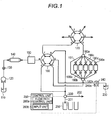
- Fig. 1 is a schematic configuration diagram of a preparative purification apparatus according to a first embodiment of the invention.
- the preparative purification apparatus includes a mobile phase container 110 which contains a mobile phase, a mobile phase liquid feeding pump 120 which delivers the mobile phase, an automatic sample injector 130 which injects a sample into the mobile phase, a separation column 140 which separates a target component in the sample, a detector 150 which detects the separated target component, a first flow path switching valve 160, a second flow path switching valve 170, a first column switching valve 180a, a second column switching valve 180b, a trap column 190 which captures a target component, a recovery/waste liquid switching valve 200, a recovery flow path 201, a waste liquid flow path 202, an eluate container 230, an eluate feeding pump 240, a recovery container 250, and a control unit 260.
- the separation column 140 has an inlet end connected to the automatic sample injector 130, and an outlet end connected to the detector 150.
- An outlet end of the detector 150 is connected to a port e of the first flow path switching valve 160.
- Various detectors for liquid chromatography such as an absorbance detector and a differential refractive index detector can be used as the detector 150.
- the first and second flow path switching valves 160 and 170 have ports a to f, and by selectively connecting one of the flow paths indicated by the solid line and broken line in Fig. 1 , it is possible to allow each port to communicate with either one of the two adjacent ports.
- the second flow path switching valve 170 is connected to the trap column via the first column switching valve 180a.
- the first column switching valve 180a selectively connects the port e of the second flow path switching valve 170 to one of the trap columns 190a to 190e and the drain flow path 191 to which no trap column is connected.
- the first flow path switching valve 160 is connected to the trap column via the second column switching valve 180b, and the second column switching valve selectively connects the port c of the first flow path switching valve 160 to the trap columns 190a to 190e and the drain flow path 191.
- the first and second column switching valves 180a and 180b are synchronized, and when one valve is switched, the other valve also switches to the same trap columns 190a to 190e or the drain flow path 191.
- the recovery/waste liquid switching valve 200 is connected to the trap column via the first flow path switching valve 160, and selectively connects the trap column 190 to either one of a recovery flow path 201 which allows a solution to flow through the recovery container 250 and a waste liquid flow path 202 for discarding the solution.
- the control unit 260 including a CPU and the like has a flow path control unit 260a and an input unit 260b, and is electrically connected to the liquid feed amount measurement unit 240a and the recovery/waste liquid switching valve 200.
- the flow path control unit 260a controls the recovery/waste liquid switching valve 200 in accordance with a preset program. Further, the initial waste liquid amount and the solution recovery amount from the input unit 260b can be set, respectively, and these set values are used for determining the switching timing of the recovery/waste liquid switching valve 200 in the flow path control unit 260a.
- the recovery container 250 has a plurality of containers which are set in accordance with the type of target components to be recovered.
- the eluate feeding pump 240 has the liquid feed amount measurement unit 240a.
- the liquid feed amount measurement unit 240a is electrically connected to the control unit 260, measures the amount of eluate fed from the eluate feeding pump 240, and transmits the measurement data to the control unit 260.
- containers in which a cleaning liquid or a diluting liquid (not illustrated) are stored or a liquid feeding pump for feeding the cleaning liquid or the diluting liquid are connected to the ports a, b, e and f of the second flow path switching valve 170, the description thereof will not be provided in the present embodiment.
- the operation of the preparative purification apparatus can be roughly divided into a capturing process and an elution process.
- the capturing process will be described.
- pure water is used as a mobile phase
- acetonitrile (CH3CN) is used as an elution solvent.
- the mobile phase contained in the mobile phase container 110 is fed by the mobile phase liquid feeding pump 120 at a constant flow rate.
- the sample containing the target component is injected into the mobile phase by the automatic sample injector 130, and delivered to the separation column 140.
- the separation column 140 the target component contained in the sample is temporally separated, and the target component is detected by the detector 150.
- the first and second flow path switching valves 160 and 170 are set in flow paths indicated by broken lines of Fig. 1 .
- the sample having passed through the detector 150 flows to the first column switching valve 180a, via the port e and the port f of the first flow path switching valve 160, and via the port d and the port c of the second flow path switching valve 170.
- the first column switching valve 180a is connected to the drain flow path 191.
- the mobile phase flows from the recovery/waste liquid switching valve 200 to the waste liquid flow path 202 via the port c and the port d of the first flow path switching valve 160, and is discarded.
- the target component flows into the first column switching valve 180a.
- the first column switching valve 180a switches the flow path to be connected from the drain flow path 191 to the trap column 190a, thereby capturing the target component in the trap column 190a.
- the mobile phase having passed through the trap column 190a flows from the recovery/waste liquid switching valve 200 to the waste liquid flow path 202 via the port c and the port d of the first flow path switching valve 160, and is discarded. Every time the target component detected by the detector 150 is switched, the first column switching valve 180a switches the flow path to capture the target components in the different trap columns for each type of target component.
- the preparative purification apparatus stops the mobile phase liquid feeding pump 120. At this time point, all the trap columns 190a to 190e are filled with the mobile phase.
- the first flow path switching valve 160 is switched to the flow path indicated by the solid line in Fig. 1 .
- the eluate feeding pump 240 feeds the elution solvent contained in the eluate container 230 to the trap column 190.
- the elution solvent passes through the port b and the port c of the first flow path switching valve 160, and flows from the second column switching valve 180b to the inlet of the trap column 190a to extrude the mobile phase filled in the trap column 190a.
- the mobile phase discharged from the outlet of the trap column 190a passes through the port c and the port d of the second flow path switching valve 170, flows through the port f and the port a of the first flow path switching valve 160, and flows into the recovery/waste liquid switching valve 200. Since the recovery/waste liquid switching valve 200 is connected to the waste liquid flow path 202 in the same manner as in the capturing process, the mobile phase is discarded as the initial waste liquid through the waste liquid flow path 202.
- the flow path control unit 260a connects the recovery/waste liquid switching valve 200 to the waste liquid flow path 202 until the measured value of the liquid feed amount measurement unit 240a becomes an initial waste liquid amount v1. At this time period, as illustrated in Figs. 2 and 3(a) , since the solvent discharged from the trap column 190a is water which is the mobile phase, the target component is not contained. Further, when the measured value of the liquid feed amount measurement unit 240a reaches the initial waste liquid amount v1, the flow path control unit 260a switches the recovery/waste liquid switching valve 200 to the recovery flow path 201 ( Fig. 3(b) ).
- the mobile phase starts to be recovered into the recovery container 250. Thereafter, the elution solvent and the turbid liquid of the mobile phase start to be gradually discharged from the trap column 190a ( Fig. 3 (c) ), and the solvent discharged at a liquid feed amount v2 of the elution solvent becomes only the elution solvent ( Fig. 3(d) ). Further, after all the target components are eluted, the flow path control unit 260a switches the recovery/waste liquid switching valve 200 to the waste liquid flow path 202 at a solution recovery amount v3, discards the elution solvent as the later waste liquid, and thereafter, the recovery process of the target component from the trap column 190a is terminated.
- the first and second column switching valves 180a and 180b are switched to the next trap column 190b, the recovery container 250 is also switched to a new container, and the recovery of the next target component is performed in the same procedure.
- the solution is recovered with the same mixing ratio as that of the trap column 190a.
- the target components are recovered by the same procedure, and when the recovery of all the trap columns is terminated, the process of the preparative purification apparatus is completed.
- Fig. 4 illustrates a schematic configuration diagram of the preparative purification apparatus according to the second embodiment.
- the configuration is the same as that of the first embodiment except that a preparative detector 470 is provided before the recovery/waste liquid switching valve 400.
- the operation of the preparative purification apparatus since the capturing process is the same as in the first embodiment, the explanation will not be provided, and the operation of the preparative detector 470 in the elution process will be mainly described.
- An eluate feeding pump 440 delivers the eluate contained in an eluate container 430 to the trap column 390.
- the eluate flows from a second column switching valve 380b to an inlet of a trap column 390a via a port b and a port c of a first flow path switching valve 360, and extrudes the mobile phase filled in a trap column 390a.
- the mobile phase discharged from the outlet of the trap column 390 passes through the detector 470 via a port c and a port d of a second flow path switching valve 370, and via the port f and then the port a of the first flow path switching valve 360, and flows into the recovery/waste liquid switching valve 400. Since the recovery/waste liquid switching valve 400 is connected to the waste liquid flow path 402 similarly to the capturing process, the mobile phase is discarded through the waste liquid flow path 402.
- the flow path control unit 460a connects the recovery/waste liquid switching valve 400 to the waste liquid flow path 402, until the target component is detected by the preparative detector 470.
- the target component is detected by the preparative detector 470, and the detection result is transmitted to the flow path control unit 460a.
- the flow path control unit 460a switches the recovery/waste liquid switching valve 400 to the recovery flow path 401, and starts the recovery of the eluate into the recovery container 450.
- the elution solvent begins to be discharged from the trap column 390a at the liquid feed amount v2 of the elution solvent. Further, at the timing when all the target components are eluted and the target components are no longer detected in the preparative detector 470, the flow path control unit 460a switches the recovery/waste liquid switching valve 400 to the waste liquid flow path 402, and terminates the recovery of the target component from the trap column 390a.
- the recovery/waste liquid switching valve 400 is switched in accordance with the measurement value of the preparative detector 470. In this case, by arbitrarily setting the flow rate and time of the eluate feeding pump, it is possible to adjust the recovery amount of the mobile phase, the elution solvent and the target component.
- the user inputs the initial waste liquid amount and the eluate recovery amount, respectively, a configuration in which the recovery start time and the recovery end time are input may be adopted. In this case, it is possible for the user to arbitrarily set the mixing ratio of the solvents, using the eluate feeding pump having a constant liquid feed amount.
- the liquid feed amount measurement unit is configured to be provided in the eluate feeding pump, the liquid feed amount measurement unit may be provided at any position other than the waste liquid flow path among the flow paths used in the preparative process.
- the number of trap columns is set to 5 in the aforementioned embodiments, the number may be 5 or more and may be less than 5. By providing a large number of trap columns, it is possible to sort out the large number of target components, respectively.
Landscapes
- Chemical & Material Sciences (AREA)
- Analytical Chemistry (AREA)
- Physics & Mathematics (AREA)
- Health & Medical Sciences (AREA)
- Life Sciences & Earth Sciences (AREA)
- Biochemistry (AREA)
- General Health & Medical Sciences (AREA)
- General Physics & Mathematics (AREA)
- Immunology (AREA)
- Pathology (AREA)
- Chemical Kinetics & Catalysis (AREA)
- Treatment Of Liquids With Adsorbents In General (AREA)
Abstract
Description
- The present invention relates to a preparative purification apparatus for separating and recovering one or more components contained in a solution, using a liquid chromatograph.
- In a pharmaceutical field, a preparative purification system using a liquid chromatograph is used for the purpose of collecting samples for storing various compounds obtained by chemical synthesis as libraries or analyzing various compounds in detail. As such a preparative separation system, systems described in
Patent Document 1 and 2 are known. - In the preparative purification systems described in
Patent Documents 1 and 2, target components (compounds) in a sample solution are introduced into separate trap columns for each target component and captured once, by being temporally separated with a liquid chromatograph. Thereafter, a solvent (elution solvent) is allowed to flow through each trap column to elute the target component captured in the column, thereby collecting a solution containing the target component in a container (collection container), and each solution is subjected to evaporation and dryness process to remove the solvent, thereby recovering the target component as solid matter. By recovering the target component as solid matter in this way, the storage and transportation are easily performed. - The evaporation and dryness process is generally carried out by a method such as heating or vacuum centrifugation of the recovered solution. The solution collected in the recovery container contains the elution solvent and a mobile phase used for capture in a trap column. Although an organic solvent is usually used for the mobile phase, in some cases, water or a solution containing water as a main component may be used. When moisture is contained in the mobile phase, since it takes time for evaporation of water, there is a need for several hours to one day in the evaporation and dryness process.
- On the other hand, when the recovered target component is used, the solidified target component may be dissolved in the solvent again and used in a solution form. In such a case, it is possible to drastically shorten the time required for the recovery process of the target component, by recovering and using the target component as a solution, without performing the evaporation and dryness process in the preparative purification system.
-
- Patent Document 1:
JP-A-2003-149217 - Patent Document 2: International Publication
WO 2009-044425 - In the case of recovering the target component in the above-mentioned preparative purification system, when the elution solvent is fed to the trap column, the elution solvent and the mobile phase are suspended in the vicinity of a boundary thereof. Since the target component is also eluted in the suspension, in order to recover the target component captured in the trap column as much as possible, the suspension is also included and collected. Therefore, the elution solvent and the mobile phase are mixed with each other in the recovered solution. When a process such as analysis of a target component is performed using the recovered solution, in a case where a mixing ratio of the mobile phase and the elution solvent is varied, there is a problem that an accurate analysis is not performed or a rapid process is not performed.
- An object to be solved by the invention is to provide a preparative purification apparatus capable of adjusting a mixing ratio of a mobile phase and an elution solvent contained in a solution to be collected.
- In order to solve the above problems, according to an aspect of the invention, there is provided a preparative purification apparatus which causes a solution eluted from a liquid chromatograph to flow through a trap column to capture a target component contained in the solution in the trap column, and thereafter, causes a elution solvent different from a mobile phase of the liquid chromatograph to flow through the trap column to elute the target component from the trap column, the apparatus including:
- a) a liquid feeding unit which feeds the elution solvent to an inlet of the trap column;
- b) a flow path switching unit which selectively connects an outlet of the trap column to one of a waste liquid flow path and a recovery flow path;
- c) a liquid feed amount measurement unit which measures an amount of the elution solvent fed to the trap column by the liquid feeding unit; and
- d) a flow path control unit which controls the flow path switching unit to connect the outlet of the trap column to the recovery flow path at a timing when the amount of the elution solvent fed to the trap column reaches a predetermined initial waste liquid amount, and thereafter, to connect the outlet of the trap column to the waste liquid flow path at a timing of reaching a predetermined solution recovery amount.
- Further, according to another aspect of the invention made to solve the above-mentioned problems, there is provided a preparative purification method in which a solution eluted from a liquid chromatograph is caused to flow through a trap column to capture a target component contained in the solution in the trap column, and thereafter, a elution solvent different from a mobile phase of the liquid chromatograph is caused to flow through the trap column to elute the target component from the trap column, the method including:
- a) feeding the elution solvent to an inlet of the trap column;
- b) measuring an amount of the elution solvent fed to the trap column; and
- c) connecting the outlet of the trap column to the recovery flow path at a timing when the amount of the elution solvent fed to the trap column reaches a predetermined initial waste liquid amount, and thereafter, connecting the outlet of the trap column to the waste liquid flow path at a timing of reaching a predetermined solution recovery amount.
- In the preparative purification apparatus according to the invention, the target component is captured in the adsorbent in the trap column, the elution solvent is fed by the liquid feeding unit in a state in which the mobile phase is accumulated in the trap column, and the elution solvent is sent to the inlet of the trap column. Thus, the mobile phase is extruded from the exit of the trap column. At this time, the mobile phase extruded from the trap column flows to the waste liquid flow path, as an initial waste liquid. When the amount of the elution solvent measured by the liquid feed amount measurement unit reaches a predetermined initial waste liquid amount, the flow path control unit controls the flow path switching unit to cause the liquid flowing out of the exit of the trap column to start to flow into the recovery flow path. When the mobile phase or the turbid liquid of the mobile phase and the elution solvent (or the suspension when the mobile phase is an aqueous system) still remains in the trap column at the time of switching the flow path, the mobile phase or the turbid liquid are sent to the recovery flow path. Thereafter, when all of the mobile phase or the turbid liquid in the trap column is discharged, the solution discharged from the trap column is switched to the elution solvent. When the amount of the elution solvent fed to the trap column reaches the predetermined solution recovery amount, the flow path control unit controls the flow path switching unit to cause the elution solvent (later waste liquid) discharged from the trap column to flow through the waste liquid flow path. This makes it possible to set the ratio of the mobile phase and the elution solvent in a predetermined amount (solution recovery amount) recovered from the trap column to a desired value.
- A solvent having a boiling point lower than that of water, such as acetonitrile and dichloromethane, can be suitably used as the elution solvent of the preparative purification apparatus. By using such a solvent, it is possible to perform the process in the case of concentrating the recovered solution in a short time.
- In the above preparative purification apparatus, the flow path control unit may be configured to control the flow path switching unit so that the mixing ratios in the recovered solutions are all constant.
- In the case of collecting and concentrating a plurality of solutions, since the time required for the concentration process varies depending on the mixing ratios in the collected solutions, it was necessary to perform a concentration process for each solution. In addition, in order to concentrate all the solutions at the same time, it is necessary to perform the concentration process after adjusting the respective solutions so that the mixing ratios in the solutions become constant, which is troublesome.
- According to the preparative purification apparatus according to the invention, since all the mixing ratios in the recovered solutions are constant, it is possible to process a plurality of solutions under uniform conditions when these solutions are concentrated.
- According to the preparative purification apparatus of the invention, the mixing ratio of the mobile phase and the elution solvent can be adjusted, by adjusting the recovery amount of the mobile phase and the elution solvent to be collected.
-
-
Fig. 1 is a schematic configuration diagram of a preparative purification apparatus according to a first embodiment of the invention. -
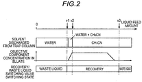
Fig. 2 is a diagram illustrating changes in a solvent and a target component in an eluate from a trap column. -
Fig. 3 is a schematic diagram illustrating a change in the solvent in the trap column. -
Fig. 4 is a schematic configuration diagram of a preparative purification apparatus according to a second embodiment of the invention. - Embodiments of the invention will be described below with reference to the drawings.
-
Fig. 1 is a schematic configuration diagram of a preparative purification apparatus according to a first embodiment of the invention. The preparative purification apparatus includes amobile phase container 110 which contains a mobile phase, a mobile phaseliquid feeding pump 120 which delivers the mobile phase, anautomatic sample injector 130 which injects a sample into the mobile phase, aseparation column 140 which separates a target component in the sample, adetector 150 which detects the separated target component, a first flowpath switching valve 160, a second flowpath switching valve 170, a firstcolumn switching valve 180a, a secondcolumn switching valve 180b, a trap column 190 which captures a target component, a recovery/wasteliquid switching valve 200, arecovery flow path 201, a wasteliquid flow path 202, aneluate container 230, aneluate feeding pump 240, arecovery container 250, and acontrol unit 260. - The
separation column 140 has an inlet end connected to theautomatic sample injector 130, and an outlet end connected to thedetector 150. An outlet end of thedetector 150 is connected to a port e of the first flowpath switching valve 160. Various detectors for liquid chromatography such as an absorbance detector and a differential refractive index detector can be used as thedetector 150. - The first and second flow
path switching valves Fig. 1 , it is possible to allow each port to communicate with either one of the two adjacent ports. - The second flow
path switching valve 170 is connected to the trap column via the firstcolumn switching valve 180a. The firstcolumn switching valve 180a selectively connects the port e of the second flowpath switching valve 170 to one of thetrap columns 190a to 190e and thedrain flow path 191 to which no trap column is connected. The first flowpath switching valve 160 is connected to the trap column via the secondcolumn switching valve 180b, and the second column switching valve selectively connects the port c of the first flowpath switching valve 160 to thetrap columns 190a to 190e and thedrain flow path 191. The first and secondcolumn switching valves same trap columns 190a to 190e or thedrain flow path 191. - The recovery/waste
liquid switching valve 200 is connected to the trap column via the first flowpath switching valve 160, and selectively connects the trap column 190 to either one of arecovery flow path 201 which allows a solution to flow through therecovery container 250 and a wasteliquid flow path 202 for discarding the solution. - The
control unit 260 including a CPU and the like has a flow path control unit 260a and aninput unit 260b, and is electrically connected to the liquid feedamount measurement unit 240a and the recovery/wasteliquid switching valve 200. The flow path control unit 260a controls the recovery/wasteliquid switching valve 200 in accordance with a preset program. Further, the initial waste liquid amount and the solution recovery amount from theinput unit 260b can be set, respectively, and these set values are used for determining the switching timing of the recovery/wasteliquid switching valve 200 in the flow path control unit 260a. - An eluate corresponding to the target component captured in the trap column 190 is contained in the
eluate container 230. Therecovery container 250 has a plurality of containers which are set in accordance with the type of target components to be recovered. - The
eluate feeding pump 240 has the liquid feedamount measurement unit 240a. The liquid feedamount measurement unit 240a is electrically connected to thecontrol unit 260, measures the amount of eluate fed from theeluate feeding pump 240, and transmits the measurement data to thecontrol unit 260. - Further, although containers in which a cleaning liquid or a diluting liquid (not illustrated) are stored or a liquid feeding pump for feeding the cleaning liquid or the diluting liquid are connected to the ports a, b, e and f of the second flow
path switching valve 170, the description thereof will not be provided in the present embodiment. - Next, the operation of the preparative purification apparatus will be described. The operation of the preparative purification apparatus can be roughly divided into a capturing process and an elution process. First, the capturing process will be described.
- In this embodiment, pure water is used as a mobile phase, and acetonitrile (CH3CN) is used as an elution solvent. First, after the user inputs the initial waste liquid amount and the solution recovery amount from the
input unit 260b, the user starts the preparative purification process. - First, the mobile phase contained in the
mobile phase container 110 is fed by the mobile phaseliquid feeding pump 120 at a constant flow rate. The sample containing the target component is injected into the mobile phase by theautomatic sample injector 130, and delivered to theseparation column 140. In theseparation column 140, the target component contained in the sample is temporally separated, and the target component is detected by thedetector 150. - In the capturing process, the first and second flow
path switching valves Fig. 1 . The sample having passed through thedetector 150 flows to the firstcolumn switching valve 180a, via the port e and the port f of the first flowpath switching valve 160, and via the port d and the port c of the second flowpath switching valve 170. Immediately after the mobile phaseliquid feeding pump 120 starts to feed liquid, since the target component is not contained in the mobile phase flowing into the firstcolumn selection valve 180a, the firstcolumn switching valve 180a is connected to thedrain flow path 191. The mobile phase flows from the recovery/wasteliquid switching valve 200 to the wasteliquid flow path 202 via the port c and the port d of the first flowpath switching valve 160, and is discarded. - When a predetermined time has elapsed from the time when the target component is detected in the
detector 150, the target component flows into the firstcolumn switching valve 180a. At this timing, the firstcolumn switching valve 180a switches the flow path to be connected from thedrain flow path 191 to thetrap column 190a, thereby capturing the target component in thetrap column 190a. The mobile phase having passed through thetrap column 190a flows from the recovery/wasteliquid switching valve 200 to the wasteliquid flow path 202 via the port c and the port d of the first flowpath switching valve 160, and is discarded. Every time the target component detected by thedetector 150 is switched, the firstcolumn switching valve 180a switches the flow path to capture the target components in the different trap columns for each type of target component. - When all the target components are collected in any one of the
trap columns 190a to 190e, the preparative purification apparatus stops the mobile phaseliquid feeding pump 120. At this time point, all thetrap columns 190a to 190e are filled with the mobile phase. - Next, an operation of recovering the target component captured in the trap column 190 to the
recovery container 250 will be described. - First, the first flow
path switching valve 160 is switched to the flow path indicated by the solid line inFig. 1 . Theeluate feeding pump 240 feeds the elution solvent contained in theeluate container 230 to the trap column 190. The elution solvent passes through the port b and the port c of the first flowpath switching valve 160, and flows from the secondcolumn switching valve 180b to the inlet of thetrap column 190a to extrude the mobile phase filled in thetrap column 190a. The mobile phase discharged from the outlet of thetrap column 190a passes through the port c and the port d of the second flowpath switching valve 170, flows through the port f and the port a of the first flowpath switching valve 160, and flows into the recovery/wasteliquid switching valve 200. Since the recovery/wasteliquid switching valve 200 is connected to the wasteliquid flow path 202 in the same manner as in the capturing process, the mobile phase is discarded as the initial waste liquid through the wasteliquid flow path 202. - The operation of the flow path control unit 260a will be described with reference to
Figs. 2 and3 . The flow path control unit 260a connects the recovery/wasteliquid switching valve 200 to the wasteliquid flow path 202 until the measured value of the liquid feedamount measurement unit 240a becomes an initial waste liquid amount v1. At this time period, as illustrated inFigs. 2 and3(a) , since the solvent discharged from thetrap column 190a is water which is the mobile phase, the target component is not contained. Further, when the measured value of the liquid feedamount measurement unit 240a reaches the initial waste liquid amount v1, the flow path control unit 260a switches the recovery/wasteliquid switching valve 200 to the recovery flow path 201 (Fig. 3(b) ). As a result, the mobile phase starts to be recovered into therecovery container 250. Thereafter, the elution solvent and the turbid liquid of the mobile phase start to be gradually discharged from thetrap column 190a (Fig. 3 (c) ), and the solvent discharged at a liquid feed amount v2 of the elution solvent becomes only the elution solvent (Fig. 3(d) ). Further, after all the target components are eluted, the flow path control unit 260a switches the recovery/wasteliquid switching valve 200 to the wasteliquid flow path 202 at a solution recovery amount v3, discards the elution solvent as the later waste liquid, and thereafter, the recovery process of the target component from thetrap column 190a is terminated. - Thereafter, the first and second
column switching valves next trap column 190b, therecovery container 250 is also switched to a new container, and the recovery of the next target component is performed in the same procedure. At this time, by setting the initial waste liquid amount v1 and the solution recovery amount v3 to the same values as those of thetrap column 190a, the solution is recovered with the same mixing ratio as that of thetrap column 190a. For other trap columns, the target components are recovered by the same procedure, and when the recovery of all the trap columns is terminated, the process of the preparative purification apparatus is completed. - Thereafter, in the case of recovering the target component using the same sample, it is possible to recover a solution with the same mixing ratio, using the same values of the initial waste liquid amount and the solution recovery amount as in the above process.
- In this way, in the preparative purification apparatus according to the above-described embodiment, it is possible to constantly adjust the mixing ratios in the recovered solutions in all the
recovery containers 250, by constantly setting the recovery amounts of the mobile phase and the eluate. - Next, a preparative purification apparatus according to a second embodiment of the invention will be described.
Fig. 4 illustrates a schematic configuration diagram of the preparative purification apparatus according to the second embodiment. In the second embodiment, the configuration is the same as that of the first embodiment except that apreparative detector 470 is provided before the recovery/wasteliquid switching valve 400. Also, regarding the operation of the preparative purification apparatus, since the capturing process is the same as in the first embodiment, the explanation will not be provided, and the operation of thepreparative detector 470 in the elution process will be mainly described. - An
eluate feeding pump 440 delivers the eluate contained in aneluate container 430 to the trap column 390. The eluate flows from a secondcolumn switching valve 380b to an inlet of atrap column 390a via a port b and a port c of a first flowpath switching valve 360, and extrudes the mobile phase filled in atrap column 390a. The mobile phase discharged from the outlet of the trap column 390 passes through thedetector 470 via a port c and a port d of a second flowpath switching valve 370, and via the port f and then the port a of the first flowpath switching valve 360, and flows into the recovery/wasteliquid switching valve 400. Since the recovery/wasteliquid switching valve 400 is connected to the wasteliquid flow path 402 similarly to the capturing process, the mobile phase is discarded through the wasteliquid flow path 402. - The flow path control
unit 460a connects the recovery/wasteliquid switching valve 400 to the wasteliquid flow path 402, until the target component is detected by thepreparative detector 470. When the suspension of the elution solvent and the mobile phase begin to be contained in the solvent discharged from thetrap column 390a, the target component is detected by thepreparative detector 470, and the detection result is transmitted to the flow path controlunit 460a. When the target component is detected, the flow path controlunit 460a switches the recovery/wasteliquid switching valve 400 to therecovery flow path 401, and starts the recovery of the eluate into therecovery container 450. - Thereafter, the elution solvent begins to be discharged from the
trap column 390a at the liquid feed amount v2 of the elution solvent. Further, at the timing when all the target components are eluted and the target components are no longer detected in thepreparative detector 470, the flow path controlunit 460a switches the recovery/wasteliquid switching valve 400 to the wasteliquid flow path 402, and terminates the recovery of the target component from thetrap column 390a. - In the preparative purification apparatus according to the second embodiment, the recovery/waste
liquid switching valve 400 is switched in accordance with the measurement value of thepreparative detector 470. In this case, by arbitrarily setting the flow rate and time of the eluate feeding pump, it is possible to adjust the recovery amount of the mobile phase, the elution solvent and the target component. - In the aforementioned embodiments, although the user inputs the initial waste liquid amount and the eluate recovery amount, respectively, a configuration in which the recovery start time and the recovery end time are input may be adopted. In this case, it is possible for the user to arbitrarily set the mixing ratio of the solvents, using the eluate feeding pump having a constant liquid feed amount.
- Although the liquid feed amount measurement unit is configured to be provided in the eluate feeding pump, the liquid feed amount measurement unit may be provided at any position other than the waste liquid flow path among the flow paths used in the preparative process. Although the number of trap columns is set to 5 in the aforementioned embodiments, the number may be 5 or more and may be less than 5. By providing a large number of trap columns, it is possible to sort out the large number of target components, respectively.
-
- 110, 310... mobile phase container
- 120, 320... mobile phase liquid feeding pump
- 130, 330... automatic sample injector
- 140, 340... separation column
- 150, 350... detector
- 160, 360... first flow path switching valve
- 170, 370... second flow path switching valve
- 180a, 380a... first column switching valve
- 180b, 380b... second column switching valve
- 190, 390... trap column
- 191, 391... drain flow path
- 200, 400... recovery/waste liquid switching valve
- 201, 401... recovery flow path
- 202, 402... waste liquid flow path
- 230, 430... eluate container
- 240, 440... eluate feeding pump
- 240a, 440a... liquid feed amount measurement unit
- 250, 450... recovery container
- 260, 460... control unit
- 260a, 460a... flow path control unit
- 260b, 460b... input unit
- 470... preparatory detector
Claims (4)
- A preparative purification apparatus which causes a solution eluted from a liquid chromatograph to flow through a trap column to capture a target component contained in the solution in the trap column, and thereafter, causes a elution solvent different from a mobile phase of the liquid chromatograph to flow through the trap column to elute the target component from the trap column, the apparatus comprising:a) a liquid feeding unit which feeds the elution solvent to an inlet of the trap column;b) a flow path switching unit which selectively connects an outlet of the trap column to one of a waste liquid flow path and a recovery flow path;c) a liquid feed amount measurement unit which measures an amount of the elution solvent fed to the trap column by the liquid feeding unit; andd) a flow path control unit which controls the flow path switching unit to connect the outlet of the trap column to the recovery flow path at a timing when the amount of the elution solvent fed to the trap column reaches a predetermined initial waste liquid amount, and thereafter, to connect the outlet of the trap column to the waste liquid flow path at a timing of reaching a predetermined solution recovery amount.
- The preparative purification apparatus according to claim 1, wherein the elution solvent has a boiling point lower than that of water.
- The preparative purification apparatus according to claim 1 or 2, wherein the flow path control unit controls the flow path switching unit so as to make all mixing ratios in a plurality of recovered solutions constant.
- A preparative purification method in which a solution eluted from a liquid chromatograph is caused to flow through a trap column to capture a target component contained in the solution in the trap column, and thereafter, a elution solvent different from a mobile phase of the liquid chromatograph is caused to flow through the trap column to elute the target component from the trap column, the method comprising:a) feeding the elution solvent to an inlet of the trap column;b) measuring an amount of the elution solvent fed to the trap column; andc) connecting the outlet of the trap column to the recovery flow path at a timing when the amount of the elution solvent fed to the trap column reaches a predetermined initial waste liquid amount, and thereafter, connecting the outlet of the trap column to the waste liquid flow path at a timing of reaching a predetermined solution recovery amount.
Applications Claiming Priority (1)
| Application Number | Priority Date | Filing Date | Title |
|---|---|---|---|
| PCT/JP2015/073702 WO2017033256A1 (en) | 2015-08-24 | 2015-08-24 | Separation/purification apparatus |
Publications (3)
| Publication Number | Publication Date |
|---|---|
| EP3343217A1 true EP3343217A1 (en) | 2018-07-04 |
| EP3343217A4 EP3343217A4 (en) | 2018-09-26 |
| EP3343217B1 EP3343217B1 (en) | 2025-07-09 |
Family
ID=58099631
Family Applications (1)
| Application Number | Title | Priority Date | Filing Date |
|---|---|---|---|
| EP15902227.6A Active EP3343217B1 (en) | 2015-08-24 | 2015-08-24 | Purification apparatus |
Country Status (5)
| Country | Link |
|---|---|
| US (1) | US10732153B2 (en) |
| EP (1) | EP3343217B1 (en) |
| JP (1) | JP6566035B2 (en) |
| CN (1) | CN107923887B (en) |
| WO (1) | WO2017033256A1 (en) |
Cited By (2)
| Publication number | Priority date | Publication date | Assignee | Title |
|---|---|---|---|---|
| WO2020173862A1 (en) * | 2019-02-28 | 2020-09-03 | Cytiva Sweden Ab | Improvements in and relating to optimizing the operation of a chromatography system |
| CN118707009A (en) * | 2024-08-30 | 2024-09-27 | 天津博蕴纯化装备材料科技有限公司 | A fully automatic chromatography purification system |
Families Citing this family (9)
| Publication number | Priority date | Publication date | Assignee | Title |
|---|---|---|---|---|
| WO2018167910A1 (en) * | 2017-03-16 | 2018-09-20 | 株式会社島津製作所 | Preparative liquid chromatograph |
| CN111316094B (en) * | 2017-12-04 | 2022-07-22 | 株式会社岛津制作所 | Liquid chromatograph |
| CN109276911A (en) * | 2018-11-29 | 2019-01-29 | 亿达康瑞生物科技(苏州)有限公司 | A kind of continuous chromatography separation system and method |
| EP3760292B1 (en) * | 2019-07-01 | 2023-04-12 | F. Hoffmann-La Roche AG | Liquid chromatography systems |
| JP7460566B2 (en) * | 2021-03-04 | 2024-04-02 | 学校法人東海大学 | Analysis method for advanced glycation products |
| CN117730254A (en) * | 2021-05-10 | 2024-03-19 | K.D.药物贝克斯巴赫有限公司 | Chromatography methods and equipment, especially for supercritical liquid chromatography |
| CN114392583A (en) * | 2022-01-28 | 2022-04-26 | 上海铨桓科技有限公司 | Chromatographic purification system and purification method |
| CN114705776B (en) * | 2022-03-31 | 2023-09-08 | 苏州汇通色谱分离纯化有限公司 | Method for purifying ginkgo flavone |
| CN116585797A (en) * | 2023-06-26 | 2023-08-15 | 中山康晟生物技术有限公司 | High-throughput affinity chromatography purification system for laboratory |
Family Cites Families (14)
| Publication number | Priority date | Publication date | Assignee | Title |
|---|---|---|---|---|
| US6002040A (en) * | 1998-05-14 | 1999-12-14 | The Standard Oil Company | Reduced pressure drop in acrylonitrile absorber via direct contact spray heat exchange |
| JP3719407B2 (en) | 2001-11-13 | 2005-11-24 | 株式会社島津製作所 | Preparative liquid chromatograph |
| FI114553B (en) * | 2001-12-31 | 2004-11-15 | Danisco Sweeteners Oy | Procedure for collecting sugar |
| JP3868899B2 (en) * | 2002-12-25 | 2007-01-17 | 株式会社島津製作所 | Liquid chromatograph |
| JP4840511B2 (en) * | 2007-10-02 | 2011-12-21 | 株式会社島津製作所 | Preparative purification equipment |
| WO2009044427A1 (en) * | 2007-10-02 | 2009-04-09 | Shimadzu Corporation | Fractionation purification apparatus |
| GB2465957B (en) | 2007-10-02 | 2012-04-04 | Shimadzu Corp | Preparative separation/ purification system |
| JP4985556B2 (en) * | 2008-06-24 | 2012-07-25 | 株式会社島津製作所 | Preparative liquid chromatograph apparatus and preparative purification method using the apparatus |
| JP5532999B2 (en) * | 2010-02-15 | 2014-06-25 | 株式会社島津製作所 | Preparative purification equipment |
| CN101972558B (en) * | 2010-11-30 | 2013-01-02 | 顾雄毅 | Expanded bed chromatographic separation column used for biochemical separation process and process flow |
| JP5821773B2 (en) | 2012-05-15 | 2015-11-24 | 株式会社島津製作所 | Control device and control method for reciprocating pump |
| JP5906936B2 (en) * | 2012-05-15 | 2016-04-20 | 株式会社島津製作所 | Preparative purification equipment |
| JP5799889B2 (en) * | 2012-05-15 | 2015-10-28 | 株式会社島津製作所 | Preparative purification equipment |
| SG10201704774VA (en) * | 2012-12-10 | 2017-07-28 | Seikagaku Kogyo Co Ltd | Novel recombinant factor c and method for producing the same, and method for measuring endotoxin |
-
2015
- 2015-08-24 JP JP2017536093A patent/JP6566035B2/en active Active
- 2015-08-24 WO PCT/JP2015/073702 patent/WO2017033256A1/en not_active Ceased
- 2015-08-24 EP EP15902227.6A patent/EP3343217B1/en active Active
- 2015-08-24 US US15/751,500 patent/US10732153B2/en active Active
- 2015-08-24 CN CN201580082607.1A patent/CN107923887B/en active Active
Cited By (3)
| Publication number | Priority date | Publication date | Assignee | Title |
|---|---|---|---|---|
| WO2020173862A1 (en) * | 2019-02-28 | 2020-09-03 | Cytiva Sweden Ab | Improvements in and relating to optimizing the operation of a chromatography system |
| US12616919B2 (en) | 2019-02-28 | 2026-05-05 | Cytiva Sweden Ab | Optimizing the operation of a chromatography system |
| CN118707009A (en) * | 2024-08-30 | 2024-09-27 | 天津博蕴纯化装备材料科技有限公司 | A fully automatic chromatography purification system |
Also Published As
| Publication number | Publication date |
|---|---|
| US20180231510A1 (en) | 2018-08-16 |
| US10732153B2 (en) | 2020-08-04 |
| EP3343217B1 (en) | 2025-07-09 |
| WO2017033256A1 (en) | 2017-03-02 |
| CN107923887B (en) | 2020-06-16 |
| JP6566035B2 (en) | 2019-08-28 |
| JPWO2017033256A1 (en) | 2018-04-19 |
| CN107923887A (en) | 2018-04-17 |
| EP3343217A4 (en) | 2018-09-26 |
Similar Documents
| Publication | Publication Date | Title |
|---|---|---|
| EP3343217B1 (en) | Purification apparatus | |
| JP4985556B2 (en) | Preparative liquid chromatograph apparatus and preparative purification method using the apparatus | |
| CN109416349B (en) | Preparative liquid chromatograph | |
| JP4840511B2 (en) | Preparative purification equipment | |
| US11774413B2 (en) | Preparative liquid chromatograph | |
| JP4840512B2 (en) | Preparative purification equipment | |
| CN101871856B (en) | Solid phase extraction and concentration system | |
| US9821250B2 (en) | Preparative separation-purification system for capturing target components | |
| WO2017122261A1 (en) | Liquid chromatograph analysis device | |
| JP6260719B2 (en) | Liquid chromatograph | |
| CN114137141A (en) | Multi-mode liquid chromatography system | |
| US12590933B2 (en) | Preparative separation and purification device and preparative separation and purification method | |
| JP2005099015A (en) | Liquid chromatography equipment | |
| KR100581019B1 (en) | Automatic pretreatment of sample | |
| US20220299485A1 (en) | Preparative liquid chromatograph and analysis method | |
| CN120154945A (en) | Preparative Chromatography Systems | |
| JP2022133555A (en) | Preparative liquid chromatograph |
Legal Events
| Date | Code | Title | Description |
|---|---|---|---|
| STAA | Information on the status of an ep patent application or granted ep patent |
Free format text: STATUS: THE INTERNATIONAL PUBLICATION HAS BEEN MADE |
|
| PUAI | Public reference made under article 153(3) epc to a published international application that has entered the european phase |
Free format text: ORIGINAL CODE: 0009012 |
|
| STAA | Information on the status of an ep patent application or granted ep patent |
Free format text: STATUS: REQUEST FOR EXAMINATION WAS MADE |
|
| 17P | Request for examination filed |
Effective date: 20180323 |
|
| AK | Designated contracting states |
Kind code of ref document: A1 Designated state(s): AL AT BE BG CH CY CZ DE DK EE ES FI FR GB GR HR HU IE IS IT LI LT LU LV MC MK MT NL NO PL PT RO RS SE SI SK SM TR |
|
| AX | Request for extension of the european patent |
Extension state: BA ME |
|
| A4 | Supplementary search report drawn up and despatched |
Effective date: 20180827 |
|
| RIC1 | Information provided on ipc code assigned before grant |
Ipc: G01N 30/40 20060101ALI20180821BHEP Ipc: G01N 30/46 20060101ALI20180821BHEP Ipc: B01D 15/24 20060101ALI20180821BHEP Ipc: G01N 30/26 20060101AFI20180821BHEP Ipc: G01N 30/82 20060101ALI20180821BHEP Ipc: G01N 30/84 20060101ALI20180821BHEP |
|
| DAV | Request for validation of the european patent (deleted) | ||
| DAX | Request for extension of the european patent (deleted) | ||
| STAA | Information on the status of an ep patent application or granted ep patent |
Free format text: STATUS: EXAMINATION IS IN PROGRESS |
|
| 17Q | First examination report despatched |
Effective date: 20210811 |
|
| GRAP | Despatch of communication of intention to grant a patent |
Free format text: ORIGINAL CODE: EPIDOSNIGR1 |
|
| STAA | Information on the status of an ep patent application or granted ep patent |
Free format text: STATUS: GRANT OF PATENT IS INTENDED |
|
| GRAJ | Information related to disapproval of communication of intention to grant by the applicant or resumption of examination proceedings by the epo deleted |
Free format text: ORIGINAL CODE: EPIDOSDIGR1 |
|
| STAA | Information on the status of an ep patent application or granted ep patent |
Free format text: STATUS: EXAMINATION IS IN PROGRESS |
|
| GRAP | Despatch of communication of intention to grant a patent |
Free format text: ORIGINAL CODE: EPIDOSNIGR1 |
|
| STAA | Information on the status of an ep patent application or granted ep patent |
Free format text: STATUS: GRANT OF PATENT IS INTENDED |
|
| INTG | Intention to grant announced |
Effective date: 20250213 |
|
| INTG | Intention to grant announced |
Effective date: 20250225 |
|
| GRAS | Grant fee paid |
Free format text: ORIGINAL CODE: EPIDOSNIGR3 |
|
| GRAA | (expected) grant |
Free format text: ORIGINAL CODE: 0009210 |
|
| STAA | Information on the status of an ep patent application or granted ep patent |
Free format text: STATUS: THE PATENT HAS BEEN GRANTED |
|
| AK | Designated contracting states |
Kind code of ref document: B1 Designated state(s): AL AT BE BG CH CY CZ DE DK EE ES FI FR GB GR HR HU IE IS IT LI LT LU LV MC MK MT NL NO PL PT RO RS SE SI SK SM TR |
|
| REG | Reference to a national code |
Ref country code: GB Ref legal event code: FG4D |
|
| REG | Reference to a national code |
Ref country code: CH Ref legal event code: EP |
|
| REG | Reference to a national code |
Ref country code: IE Ref legal event code: FG4D |
|
| REG | Reference to a national code |
Ref country code: DE Ref legal event code: R096 Ref document number: 602015091982 Country of ref document: DE |
|
| PGFP | Annual fee paid to national office [announced via postgrant information from national office to epo] |
Ref country code: DE Payment date: 20250827 Year of fee payment: 11 |
|
| PGFP | Annual fee paid to national office [announced via postgrant information from national office to epo] |
Ref country code: GB Payment date: 20250827 Year of fee payment: 11 |
|
| PGFP | Annual fee paid to national office [announced via postgrant information from national office to epo] |
Ref country code: FR Payment date: 20250827 Year of fee payment: 11 |
|
| REG | Reference to a national code |
Ref country code: NL Ref legal event code: MP Effective date: 20250709 |
|
| PG25 | Lapsed in a contracting state [announced via postgrant information from national office to epo] |
Ref country code: PT Free format text: LAPSE BECAUSE OF FAILURE TO SUBMIT A TRANSLATION OF THE DESCRIPTION OR TO PAY THE FEE WITHIN THE PRESCRIBED TIME-LIMIT Effective date: 20251110 |
|
| PG25 | Lapsed in a contracting state [announced via postgrant information from national office to epo] |
Ref country code: NL Free format text: LAPSE BECAUSE OF FAILURE TO SUBMIT A TRANSLATION OF THE DESCRIPTION OR TO PAY THE FEE WITHIN THE PRESCRIBED TIME-LIMIT Effective date: 20250709 |
|
| REG | Reference to a national code |
Ref country code: AT Ref legal event code: MK05 Ref document number: 1812236 Country of ref document: AT Kind code of ref document: T Effective date: 20250709 |
|
| PG25 | Lapsed in a contracting state [announced via postgrant information from national office to epo] |
Ref country code: IS Free format text: LAPSE BECAUSE OF FAILURE TO SUBMIT A TRANSLATION OF THE DESCRIPTION OR TO PAY THE FEE WITHIN THE PRESCRIBED TIME-LIMIT Effective date: 20251109 |
|
| PG25 | Lapsed in a contracting state [announced via postgrant information from national office to epo] |
Ref country code: NO Free format text: LAPSE BECAUSE OF FAILURE TO SUBMIT A TRANSLATION OF THE DESCRIPTION OR TO PAY THE FEE WITHIN THE PRESCRIBED TIME-LIMIT Effective date: 20251009 |
|
| REG | Reference to a national code |
Ref country code: LT Ref legal event code: MG9D |
|
| PG25 | Lapsed in a contracting state [announced via postgrant information from national office to epo] |
Ref country code: AT Free format text: LAPSE BECAUSE OF FAILURE TO SUBMIT A TRANSLATION OF THE DESCRIPTION OR TO PAY THE FEE WITHIN THE PRESCRIBED TIME-LIMIT Effective date: 20250709 |
|
| PG25 | Lapsed in a contracting state [announced via postgrant information from national office to epo] |
Ref country code: FI Free format text: LAPSE BECAUSE OF FAILURE TO SUBMIT A TRANSLATION OF THE DESCRIPTION OR TO PAY THE FEE WITHIN THE PRESCRIBED TIME-LIMIT Effective date: 20250709 |
|
| PG25 | Lapsed in a contracting state [announced via postgrant information from national office to epo] |
Ref country code: HR Free format text: LAPSE BECAUSE OF FAILURE TO SUBMIT A TRANSLATION OF THE DESCRIPTION OR TO PAY THE FEE WITHIN THE PRESCRIBED TIME-LIMIT Effective date: 20250709 |
|
| PG25 | Lapsed in a contracting state [announced via postgrant information from national office to epo] |
Ref country code: GR Free format text: LAPSE BECAUSE OF FAILURE TO SUBMIT A TRANSLATION OF THE DESCRIPTION OR TO PAY THE FEE WITHIN THE PRESCRIBED TIME-LIMIT Effective date: 20251010 |
|
| PG25 | Lapsed in a contracting state [announced via postgrant information from national office to epo] |
Ref country code: SE Free format text: LAPSE BECAUSE OF FAILURE TO SUBMIT A TRANSLATION OF THE DESCRIPTION OR TO PAY THE FEE WITHIN THE PRESCRIBED TIME-LIMIT Effective date: 20250709 |
|
| PG25 | Lapsed in a contracting state [announced via postgrant information from national office to epo] |
Ref country code: LV Free format text: LAPSE BECAUSE OF FAILURE TO SUBMIT A TRANSLATION OF THE DESCRIPTION OR TO PAY THE FEE WITHIN THE PRESCRIBED TIME-LIMIT Effective date: 20250709 |
|
| PG25 | Lapsed in a contracting state [announced via postgrant information from national office to epo] |
Ref country code: BG Free format text: LAPSE BECAUSE OF FAILURE TO SUBMIT A TRANSLATION OF THE DESCRIPTION OR TO PAY THE FEE WITHIN THE PRESCRIBED TIME-LIMIT Effective date: 20250709 Ref country code: PL Free format text: LAPSE BECAUSE OF FAILURE TO SUBMIT A TRANSLATION OF THE DESCRIPTION OR TO PAY THE FEE WITHIN THE PRESCRIBED TIME-LIMIT Effective date: 20250709 |
|
| PG25 | Lapsed in a contracting state [announced via postgrant information from national office to epo] |
Ref country code: RS Free format text: LAPSE BECAUSE OF FAILURE TO SUBMIT A TRANSLATION OF THE DESCRIPTION OR TO PAY THE FEE WITHIN THE PRESCRIBED TIME-LIMIT Effective date: 20251009 |
|
| PG25 | Lapsed in a contracting state [announced via postgrant information from national office to epo] |
Ref country code: ES Free format text: LAPSE BECAUSE OF FAILURE TO SUBMIT A TRANSLATION OF THE DESCRIPTION OR TO PAY THE FEE WITHIN THE PRESCRIBED TIME-LIMIT Effective date: 20250709 |
|
| PG25 | Lapsed in a contracting state [announced via postgrant information from national office to epo] |
Ref country code: RO Free format text: LAPSE BECAUSE OF FAILURE TO SUBMIT A TRANSLATION OF THE DESCRIPTION OR TO PAY THE FEE WITHIN THE PRESCRIBED TIME-LIMIT Effective date: 20250709 |
|
| REG | Reference to a national code |
Ref country code: CH Ref legal event code: H13 Free format text: ST27 STATUS EVENT CODE: U-0-0-H10-H13 (AS PROVIDED BY THE NATIONAL OFFICE) Effective date: 20260324 |
|
| PG25 | Lapsed in a contracting state [announced via postgrant information from national office to epo] |
Ref country code: SM Free format text: LAPSE BECAUSE OF FAILURE TO SUBMIT A TRANSLATION OF THE DESCRIPTION OR TO PAY THE FEE WITHIN THE PRESCRIBED TIME-LIMIT Effective date: 20250709 |
|
| PG25 | Lapsed in a contracting state [announced via postgrant information from national office to epo] |
Ref country code: DK Free format text: LAPSE BECAUSE OF FAILURE TO SUBMIT A TRANSLATION OF THE DESCRIPTION OR TO PAY THE FEE WITHIN THE PRESCRIBED TIME-LIMIT Effective date: 20250709 |
|
| PG25 | Lapsed in a contracting state [announced via postgrant information from national office to epo] |
Ref country code: LU Free format text: LAPSE BECAUSE OF NON-PAYMENT OF DUE FEES Effective date: 20250824 Ref country code: IT Free format text: LAPSE BECAUSE OF FAILURE TO SUBMIT A TRANSLATION OF THE DESCRIPTION OR TO PAY THE FEE WITHIN THE PRESCRIBED TIME-LIMIT Effective date: 20250709 |
|
| PG25 | Lapsed in a contracting state [announced via postgrant information from national office to epo] |
Ref country code: CZ Free format text: LAPSE BECAUSE OF FAILURE TO SUBMIT A TRANSLATION OF THE DESCRIPTION OR TO PAY THE FEE WITHIN THE PRESCRIBED TIME-LIMIT Effective date: 20250709 Ref country code: CH Free format text: LAPSE BECAUSE OF NON-PAYMENT OF DUE FEES Effective date: 20250831 |
|
| PG25 | Lapsed in a contracting state [announced via postgrant information from national office to epo] |
Ref country code: SK Free format text: LAPSE BECAUSE OF FAILURE TO SUBMIT A TRANSLATION OF THE DESCRIPTION OR TO PAY THE FEE WITHIN THE PRESCRIBED TIME-LIMIT Effective date: 20250709 Ref country code: EE Free format text: LAPSE BECAUSE OF FAILURE TO SUBMIT A TRANSLATION OF THE DESCRIPTION OR TO PAY THE FEE WITHIN THE PRESCRIBED TIME-LIMIT Effective date: 20250709 |
|
| PLBE | No opposition filed within time limit |
Free format text: ORIGINAL CODE: 0009261 |
|
| STAA | Information on the status of an ep patent application or granted ep patent |
Free format text: STATUS: NO OPPOSITION FILED WITHIN TIME LIMIT |