EP3343201A1 - Zähl- und charakterisierungsverfahren von teilchen in einem fluid in bewegung - Google Patents
Zähl- und charakterisierungsverfahren von teilchen in einem fluid in bewegung Download PDFInfo
- Publication number
- EP3343201A1 EP3343201A1 EP17210133.9A EP17210133A EP3343201A1 EP 3343201 A1 EP3343201 A1 EP 3343201A1 EP 17210133 A EP17210133 A EP 17210133A EP 3343201 A1 EP3343201 A1 EP 3343201A1
- Authority
- EP
- European Patent Office
- Prior art keywords
- image
- max
- particles
- instant
- acquired
- Prior art date
- Legal status (The legal status is an assumption and is not a legal conclusion. Google has not performed a legal analysis and makes no representation as to the accuracy of the status listed.)
- Granted
Links
- 239000002245 particle Substances 0.000 title claims abstract description 231
- 239000012530 fluid Substances 0.000 title claims abstract description 70
- 238000000034 method Methods 0.000 title claims abstract description 50
- 238000006073 displacement reaction Methods 0.000 claims abstract description 152
- 230000033001 locomotion Effects 0.000 claims abstract description 21
- 238000001514 detection method Methods 0.000 claims description 29
- 238000005286 illumination Methods 0.000 claims description 13
- 238000004364 calculation method Methods 0.000 claims description 10
- 230000015572 biosynthetic process Effects 0.000 claims description 9
- GNFTZDOKVXKIBK-UHFFFAOYSA-N 3-(2-methoxyethoxy)benzohydrazide Chemical compound COCCOC1=CC=CC(C(=O)NN)=C1 GNFTZDOKVXKIBK-UHFFFAOYSA-N 0.000 claims description 7
- 238000010200 validation analysis Methods 0.000 claims description 7
- 230000008569 process Effects 0.000 claims description 6
- 230000001902 propagating effect Effects 0.000 claims description 5
- FGUUSXIOTUKUDN-IBGZPJMESA-N C1(=CC=CC=C1)N1C2=C(NC([C@H](C1)NC=1OC(=NN=1)C1=CC=CC=C1)=O)C=CC=C2 Chemical compound C1(=CC=CC=C1)N1C2=C(NC([C@H](C1)NC=1OC(=NN=1)C1=CC=CC=C1)=O)C=CC=C2 FGUUSXIOTUKUDN-IBGZPJMESA-N 0.000 claims description 4
- 230000003287 optical effect Effects 0.000 abstract description 5
- 230000006870 function Effects 0.000 description 10
- 230000000694 effects Effects 0.000 description 8
- 238000003384 imaging method Methods 0.000 description 8
- 238000012360 testing method Methods 0.000 description 7
- 238000000605 extraction Methods 0.000 description 6
- 238000001914 filtration Methods 0.000 description 6
- 239000013598 vector Substances 0.000 description 6
- 239000007788 liquid Substances 0.000 description 5
- 230000003595 spectral effect Effects 0.000 description 5
- 241001080024 Telles Species 0.000 description 4
- 241000897276 Termes Species 0.000 description 4
- 230000008901 benefit Effects 0.000 description 4
- 239000004793 Polystyrene Substances 0.000 description 3
- 230000001419 dependent effect Effects 0.000 description 3
- 239000000428 dust Substances 0.000 description 3
- 239000012071 phase Substances 0.000 description 3
- 229920002223 polystyrene Polymers 0.000 description 3
- 241000894006 Bacteria Species 0.000 description 2
- 240000008042 Zea mays Species 0.000 description 2
- 238000010521 absorption reaction Methods 0.000 description 2
- 238000013459 approach Methods 0.000 description 2
- 239000011324 bead Substances 0.000 description 2
- 239000013060 biological fluid Substances 0.000 description 2
- 238000002592 echocardiography Methods 0.000 description 2
- 230000005484 gravity Effects 0.000 description 2
- 230000004899 motility Effects 0.000 description 2
- 239000007787 solid Substances 0.000 description 2
- 238000012935 Averaging Methods 0.000 description 1
- 241000588724 Escherichia coli Species 0.000 description 1
- 241000295644 Staphylococcaceae Species 0.000 description 1
- 239000000443 aerosol Substances 0.000 description 1
- 238000004458 analytical method Methods 0.000 description 1
- 239000008346 aqueous phase Substances 0.000 description 1
- 230000035605 chemotaxis Effects 0.000 description 1
- 230000003750 conditioning effect Effects 0.000 description 1
- 230000005684 electric field Effects 0.000 description 1
- 239000003344 environmental pollutant Substances 0.000 description 1
- 238000009499 grossing Methods 0.000 description 1
- 230000036541 health Effects 0.000 description 1
- 238000010191 image analysis Methods 0.000 description 1
- 239000011159 matrix material Substances 0.000 description 1
- 238000005259 measurement Methods 0.000 description 1
- 239000011325 microbead Substances 0.000 description 1
- 244000005700 microbiome Species 0.000 description 1
- 239000013307 optical fiber Substances 0.000 description 1
- 238000012634 optical imaging Methods 0.000 description 1
- 238000005457 optimization Methods 0.000 description 1
- 238000000917 particle-image velocimetry Methods 0.000 description 1
- 231100000719 pollutant Toxicity 0.000 description 1
- 238000012545 processing Methods 0.000 description 1
- 230000000644 propagated effect Effects 0.000 description 1
- 230000000717 retained effect Effects 0.000 description 1
- 230000011218 segmentation Effects 0.000 description 1
- 238000013519 translation Methods 0.000 description 1
- XLYOFNOQVPJJNP-UHFFFAOYSA-N water Substances O XLYOFNOQVPJJNP-UHFFFAOYSA-N 0.000 description 1
Images


Classifications
-
- G—PHYSICS
- G06—COMPUTING; CALCULATING OR COUNTING
- G06T—IMAGE DATA PROCESSING OR GENERATION, IN GENERAL
- G06T7/00—Image analysis
- G06T7/20—Analysis of motion
- G06T7/246—Analysis of motion using feature-based methods, e.g. the tracking of corners or segments
- G06T7/248—Analysis of motion using feature-based methods, e.g. the tracking of corners or segments involving reference images or patches
-
- G—PHYSICS
- G03—PHOTOGRAPHY; CINEMATOGRAPHY; ANALOGOUS TECHNIQUES USING WAVES OTHER THAN OPTICAL WAVES; ELECTROGRAPHY; HOLOGRAPHY
- G03H—HOLOGRAPHIC PROCESSES OR APPARATUS
- G03H1/00—Holographic processes or apparatus using light, infrared or ultraviolet waves for obtaining holograms or for obtaining an image from them; Details peculiar thereto
- G03H1/04—Processes or apparatus for producing holograms
- G03H1/0443—Digital holography, i.e. recording holograms with digital recording means
-
- G—PHYSICS
- G01—MEASURING; TESTING
- G01N—INVESTIGATING OR ANALYSING MATERIALS BY DETERMINING THEIR CHEMICAL OR PHYSICAL PROPERTIES
- G01N15/00—Investigating characteristics of particles; Investigating permeability, pore-volume, or surface-area of porous materials
- G01N15/10—Investigating individual particles
- G01N15/14—Electro-optical investigation, e.g. flow cytometers
- G01N15/1429—Electro-optical investigation, e.g. flow cytometers using an analyser being characterised by its signal processing
-
- G—PHYSICS
- G01—MEASURING; TESTING
- G01N—INVESTIGATING OR ANALYSING MATERIALS BY DETERMINING THEIR CHEMICAL OR PHYSICAL PROPERTIES
- G01N15/00—Investigating characteristics of particles; Investigating permeability, pore-volume, or surface-area of porous materials
- G01N15/10—Investigating individual particles
- G01N15/14—Electro-optical investigation, e.g. flow cytometers
- G01N15/1434—Electro-optical investigation, e.g. flow cytometers using an analyser being characterised by its optical arrangement
-
- G—PHYSICS
- G01—MEASURING; TESTING
- G01N—INVESTIGATING OR ANALYSING MATERIALS BY DETERMINING THEIR CHEMICAL OR PHYSICAL PROPERTIES
- G01N15/00—Investigating characteristics of particles; Investigating permeability, pore-volume, or surface-area of porous materials
- G01N15/10—Investigating individual particles
- G01N15/14—Electro-optical investigation, e.g. flow cytometers
- G01N15/1456—Electro-optical investigation, e.g. flow cytometers without spatial resolution of the texture or inner structure of the particle, e.g. processing of pulse signals
- G01N15/1459—Electro-optical investigation, e.g. flow cytometers without spatial resolution of the texture or inner structure of the particle, e.g. processing of pulse signals the analysis being performed on a sample stream
-
- H—ELECTRICITY
- H04—ELECTRIC COMMUNICATION TECHNIQUE
- H04N—PICTORIAL COMMUNICATION, e.g. TELEVISION
- H04N23/00—Cameras or camera modules comprising electronic image sensors; Control thereof
- H04N23/56—Cameras or camera modules comprising electronic image sensors; Control thereof provided with illuminating means
-
- G—PHYSICS
- G01—MEASURING; TESTING
- G01N—INVESTIGATING OR ANALYSING MATERIALS BY DETERMINING THEIR CHEMICAL OR PHYSICAL PROPERTIES
- G01N15/00—Investigating characteristics of particles; Investigating permeability, pore-volume, or surface-area of porous materials
- G01N15/10—Investigating individual particles
- G01N2015/1006—Investigating individual particles for cytology
-
- G—PHYSICS
- G01—MEASURING; TESTING
- G01N—INVESTIGATING OR ANALYSING MATERIALS BY DETERMINING THEIR CHEMICAL OR PHYSICAL PROPERTIES
- G01N15/00—Investigating characteristics of particles; Investigating permeability, pore-volume, or surface-area of porous materials
- G01N15/10—Investigating individual particles
- G01N15/14—Electro-optical investigation, e.g. flow cytometers
- G01N15/1434—Electro-optical investigation, e.g. flow cytometers using an analyser being characterised by its optical arrangement
- G01N2015/144—Imaging characterised by its optical setup
-
- G—PHYSICS
- G01—MEASURING; TESTING
- G01N—INVESTIGATING OR ANALYSING MATERIALS BY DETERMINING THEIR CHEMICAL OR PHYSICAL PROPERTIES
- G01N15/00—Investigating characteristics of particles; Investigating permeability, pore-volume, or surface-area of porous materials
- G01N15/10—Investigating individual particles
- G01N15/14—Electro-optical investigation, e.g. flow cytometers
- G01N15/1434—Electro-optical investigation, e.g. flow cytometers using an analyser being characterised by its optical arrangement
- G01N2015/1454—Electro-optical investigation, e.g. flow cytometers using an analyser being characterised by its optical arrangement using phase shift or interference, e.g. for improving contrast
-
- G—PHYSICS
- G01—MEASURING; TESTING
- G01N—INVESTIGATING OR ANALYSING MATERIALS BY DETERMINING THEIR CHEMICAL OR PHYSICAL PROPERTIES
- G01N15/00—Investigating characteristics of particles; Investigating permeability, pore-volume, or surface-area of porous materials
- G01N15/10—Investigating individual particles
- G01N15/14—Electro-optical investigation, e.g. flow cytometers
- G01N2015/1486—Counting the particles
-
- G—PHYSICS
- G03—PHOTOGRAPHY; CINEMATOGRAPHY; ANALOGOUS TECHNIQUES USING WAVES OTHER THAN OPTICAL WAVES; ELECTROGRAPHY; HOLOGRAPHY
- G03H—HOLOGRAPHIC PROCESSES OR APPARATUS
- G03H1/00—Holographic processes or apparatus using light, infrared or ultraviolet waves for obtaining holograms or for obtaining an image from them; Details peculiar thereto
- G03H1/0005—Adaptation of holography to specific applications
- G03H2001/0033—Adaptation of holography to specific applications in hologrammetry for measuring or analysing
-
- G—PHYSICS
- G03—PHOTOGRAPHY; CINEMATOGRAPHY; ANALOGOUS TECHNIQUES USING WAVES OTHER THAN OPTICAL WAVES; ELECTROGRAPHY; HOLOGRAPHY
- G03H—HOLOGRAPHIC PROCESSES OR APPARATUS
- G03H1/00—Holographic processes or apparatus using light, infrared or ultraviolet waves for obtaining holograms or for obtaining an image from them; Details peculiar thereto
- G03H1/04—Processes or apparatus for producing holograms
- G03H1/0443—Digital holography, i.e. recording holograms with digital recording means
- G03H2001/0447—In-line recording arrangement
-
- G—PHYSICS
- G03—PHOTOGRAPHY; CINEMATOGRAPHY; ANALOGOUS TECHNIQUES USING WAVES OTHER THAN OPTICAL WAVES; ELECTROGRAPHY; HOLOGRAPHY
- G03H—HOLOGRAPHIC PROCESSES OR APPARATUS
- G03H2210/00—Object characteristics
- G03H2210/62—Moving object
-
- G—PHYSICS
- G06—COMPUTING; CALCULATING OR COUNTING
- G06T—IMAGE DATA PROCESSING OR GENERATION, IN GENERAL
- G06T2207/00—Indexing scheme for image analysis or image enhancement
- G06T2207/10—Image acquisition modality
- G06T2207/10141—Special mode during image acquisition
- G06T2207/10152—Varying illumination
-
- G—PHYSICS
- G06—COMPUTING; CALCULATING OR COUNTING
- G06T—IMAGE DATA PROCESSING OR GENERATION, IN GENERAL
- G06T2207/00—Indexing scheme for image analysis or image enhancement
- G06T2207/20—Special algorithmic details
- G06T2207/20212—Image combination
- G06T2207/20224—Image subtraction
Definitions
- the technical field of the invention is the counting of particles flowing in a fluidic chamber using an optical method.
- the document WO2008090330 describes a device allowing the observation of samples comprising cells by imaging without a lens.
- the sample is disposed between a light source and an image sensor without having an optical image forming system between the sample and the image sensor.
- the image sensor collects an image, also called a hologram, formed of interference patterns between the light wave emitted by the light source and transmitted by the sample, and diffraction waves, resulting from the diffraction by the sample of the light wave emitted by the light source.
- These interference patterns are generally formed by a succession of concentric rings. They are sometimes called diffraction patterns, or designated by the term "diffraction pattern". We thus acquire images whose field of view is much larger than that of a microscope.
- each cell may be associated with an interference pattern; their enumeration allows the counting of the cells present in the sample.
- the hologram does not allow reliable counting of cells when concentration increases, and / or when the particles are in motion.
- the method also exhibits limitations when the hologram has a low noise ratio, for example when the particle size is small or when a particle has a refractive index close to that of the sample medium.
- This document also describes a determination of a three-dimensional position of particles by combining different holograms.
- This document also describes an application of lensless imaging to particle tracking, especially in a chemotaxis application, the particles being mobile with respect to a medium in which they are immersed.
- the patent application EP3031180 describes a determination of a three-dimensional position of particles, by applying a digital focusing algorithm, to an image obtained by defocused imaging.
- the patent application US2012 / 148141 describes a process incorporating the principles of WO2008090330 , by implementing a holographic reconstruction algorithm with a succession of images acquired to reconstruct complex images of spermatozoa.
- the goal is to characterize their motility. It is a process based on an individual tracking of moving particle trajectories in an immobile fluid, based on three-dimensional coordinates of the particles, obtained by the holographic reconstruction. Indeed, such a reconstruction makes it possible to provide an estimate of a distance between an image sensor and a particle, making it possible to access a so-called depth information, completing the two-dimensional information obtained by conventional image sensors. .
- the method makes it possible to determine a displacement model of each particle, the displacement model being a result obtained by the implementation of the method.
- Particle Imaging Velocimetry implement optical particle detection methods so as to characterize their movement, which is representative of the movement of the fluid studied.
- the inventors of the present invention have proposed a method for locating and counting particles circulating in a fluid chamber, which can be automated and used in a fluid in motion.
- the method can be implemented automatically, and address high particle speeds or amounts.
- the process can allow discrimination between different types of particles, so as to count the number of particles of different types, based on their respective displacements.
- Steps f) and g) are optional. When they are not implemented, the method comprises a step of determining a number of particles and / or the coordinates of the particles at the first instant and / or the second instant from the potential displacements determined during the step e).
- the fluid may flow in a flow direction, and the particle displacement may be in another direction not parallel to said flow direction.
- the method may be such that no image forming optics are disposed between the image sensor and the fluid chamber. It may also be such that the image sensor has an image forming optics between the image sensor and the fluid chamber, the image formed in step b) being a defocused image.
- the selection of three-dimensional positions can be performed by forming an image of the maximas and by determining a signal-to-noise ratio at each pixel of the maxima image, as previously described.
- the Figure 1A represents an example of a device for implementing the invention.
- a light source 11 is able to emit a light wave 12, called incident light wave, propagating towards a sample 10, along an axis of propagation Z.
- the light wave is emitted according to a spectral band ⁇ .
- Sample 10 is a sample comprising particles 10a which it is desired to count, the particles being placed in a transparent or translucent carrier fluid medium 10b.
- the particles are small elements, and are inscribed in a diameter between 0.1 microns and 100 microns; or between 1 ⁇ m and 100 ⁇ m.
- the particles are solid or liquid. It may be dust, or cells or microorganisms or microbeads, usually used in biological applications, or microalgae. It may also be droplets that are insoluble in the fluid 10b, for example oil droplets dispersed in an aqueous phase.
- the carrier medium 10b is a fluid, for example air or a liquid, for example water or a biological fluid.
- the sample may be for example an aerosol comprising particles suspended in a gas, the latter may especially be air.
- the sample 10 is contained in a fluidic chamber 15.
- the thickness e of the sample 10 along the axis of propagation typically varies between 10 ⁇ m and 2 cm or 3 cm, and is preferably between 20 ⁇ m and 1 ⁇ m. cm.
- the sample extends in a plane, called the plane of the sample, preferably perpendicular to the axis of propagation Z.
- the fluidic chamber 15 is held on a support 10s facing the image sensor 20.
- the particles 10a are movable in the fluidic chamber 15, being carried by the fluid 10b, the latter being movable in the fluid chamber 15.
- the fluid flows in the fluidic chamber 15, along an axis of longitudinal flow X.
- the particles 10a are then driven by the fluidic movement of the medium 10b, the latter acting as a carrier medium, and forming a fluidic flow inside the fluidic chamber 15.
- the displacement of the medium is modelable.
- the particles 10a can also be movable relative to the medium 10b, the movement of the particles with respect to the fluid carrying them being referred to as particle movement.
- the displacement of the particles 10a in the fluidic chamber 15 is not random and obeys a predetermined displacement pattern, combining the fluid motion of the medium 10b and, optionally, the particulate movement of the particles with respect to the fluid.
- the distance D between the light source 11 and the sample 10 is preferably greater than 1 cm. It is preferably between 2 and 30 cm.
- the light source, seen by the sample is considered as point. This means that its diameter (or diagonal) is preferably less than one-tenth, better one-hundredth of the distance between the sample and the light source.
- the light source 11 is a laser diode.
- the light source 11 is a white light source or a light emitting diode.
- a spatial filter is advantageously arranged between the light source and the sample, so that the light source appears as punctual.
- the spatial filter may be a pinhole or an optical fiber.
- a wavelength filter is also preferably placed between the light source and the sample, in order to adjust the emission spectral band ⁇ of the incident light wave 12.
- the emission spectral band ⁇ of the light wave incident light wave 12 has a width less than 100 nm.
- Spectral bandwidth means a width at half height of said spectral band.
- the fluidic chamber 15 is disposed between the light source 11 and the image sensor 20 previously mentioned.
- the latter preferably extends parallel to, or substantially parallel to, the plane along which the sample extends.
- substantially parallel means that the two elements may not be strictly parallel, an angular tolerance of a few degrees, less than 20 ° or 10 ° being allowed.
- the image sensor 20 is able to form an image I according to a detection plane P 0 .
- the image sensor comprises an array of pixels, with each pixel being associated with coordinates (x, y), called radial coordinates, in the detection plane P 0 .
- the image sensor may in particular be a CCD type sensor or a CMOS.
- the detection plane P 0 preferably extends perpendicular to the propagation axis Z of the incident light wave 12.
- the distance between the sample 10 and the pixel matrix of the image sensor 20 is between a distance minimum dmin and a maximum distance d max.
- the thickness e of the fluidic chamber corresponds to the difference between d max and d min .
- d min may be between 50 microns and 2 cm, preferably between 100 microns and 2 mm.
- the thickness of the fluidic chamber is generally between 100 ⁇ m and 5 cm.
- magnification optics between the image sensor 20 and the sample 10. This does not prevent the possible presence of microlenses focusing at each pixel of the image sensor 20, the latter having no function of magnification of the image acquired by the image sensor.
- the image sensor 20 is thus placed in a configuration called imaging without a lens. Such a configuration makes it possible to obtain a high field of observation.
- Other configurations are nevertheless conceivable, in particular a configuration according to which a focusing optics is interposed between the image sensor 20 and the fluidic chamber 15. In such a configuration, the image sensor acquires a defocused image of the image sensor. sample 10, as described in EP3031180 .
- the image I acquired by the image sensor 20 has interference patterns (or diffraction patterns), each interference pattern being generated by a particle 10a of the sample 10.
- the processor is a microprocessor connected to a programmable memory 32 in which is stored a sequence of instructions to perform the image processing operations and calculations described in this description.
- the processor may be coupled to a screen 34 for displaying images acquired by the image sensor 20 or calculated by the processor 30.
- the fluidic chamber 15 is fixed with respect to the image sensor 20. Thus, the fluid medium 10b and the particles 10a flowing in the fluidic chamber are moving relative to the image sensor 20.
- a propagation operator h so as to calculate a complex quantity representative of the exposure light wave. It is then possible to calculate a complex expression A of the light wave 14 at any coordinate point ( x, y, z ) of the space, and in particular according to a reconstruction surface extending towards the image sensor 20
- the reconstruction surface is usually a plane P z , called the reconstruction plane, extending parallel to the image sensor 20, at a coordinate z of the detection plane P 0 .
- the reconstruction plane P z is then parallel to the detection plane P 0 .
- the propagation operator h describes the propagation of light between the detection plane P 0 and the reconstruction plane P z .
- a feature of the invention is that the particles 10a move, being driven by the fluid 10b.
- the fluid moves between an inlet and an outlet of the fluidic chamber 15, along an axis of flow X.
- the time shift ⁇ t t 2 - t 1 between the two instants depending on a maximum speed V max of the fluid in the fluidic chamber 15 as well as the size of the part of the the fluidic chamber seen by the sensor.
- V max maximum speed of the fluid in the fluidic chamber 15
- L denotes a dimension of the fluidic chamber 15, seen by the image sensor 20, along the axis of propagation X of the fluid, it is preferable that: ⁇ t ⁇ The 2 V max .
- the image sensor acquires two successive images I ( t 1 ) and I ( t 2 ), respectively at the first instant t 1 and at the second instant t 2 . From each image, we obtain three-dimensional coordinates of the particles at each moment.
- the same image of the fluidic chamber is acquired at both times, the acquisition of this image being performed at the first instant and at the second instant.
- Step 100 Acquisition It is to acquire an image I ( t i ) at different times t i , according to an acquisition frequency.
- the instant t i is a first moment t 1 and acquires an image called first image I ( t 1 ).
- the instant t i is a second instant t 2 , the second instant being later than the first instant.
- the image acquired at time t 2 is a second image I ( t 2 ).
- Step 110 extraction of an image of interest from the acquired image, the image of interest representing a mobile component I m ( t i ) of the acquired image.
- the acquired image I ( t i ) comprises a component I f ( t i ), called the fixed component, representing the elements considered as not dependent on time, and a component I m ( t i ) called the mobile component, representing the considered elements as in motion in the image.
- the particles moving in the sample are in motion and form the motion component.
- the first filtering aims to remove the fixed component of the acquired image.
- the fixed component can be obtained by means of one or more images acquired at different times different from the acquisition time of the filtered image.
- the fixed component I f ( t i ) can be estimated by an initial image I ( t 0 ), acquired while no particle circulates in the fluidic chamber 15. This makes it possible to obtain an image of the fixed elements, for example dust, not representative of the mobile particles to be counted.
- the estimation of the fixed component is thus renewed with each new acquisition of an image. It corresponds to an average of two images respectively acquired before and after the acquired image considered, the average being weighted by a weighting factor of 1 ⁇ 2. This allows a regular update of the fixed component.
- the fixed component is subtracted from each acquired image, so as to obtain a mobile component I v , representative of the moving elements in the image, and in particular moving particles.
- I v t i I t i - I f i
- the mobile component forms an image of interest on the basis of which the following steps are performed.
- the image of interest is noted I v ( t 1 ).
- the image of interest is noted I v ( t 2 ).
- the Figures 2B to 2D represent modeled examples of intensity profiles of a hologram, corresponding to a particle, on an image acquired by the image sensor 20, respectively at times t i -1 , t i , and t i + 1 .
- the particle moves along the axis of flow of the fluid X, which translates into a translation of the hologram, the latter being represented by a hug on each of these figures.
- the undulations observed on either side of the hologram correspond to the effect of mounting imperfections. These imperfections include nonuniformities of illumination and interference between reflections taking place at the interfaces of the chamber. This is reflected in the fact that Figures 2B, 2C and 2D , the profiles at the level of holograms are dissymmetrical and different.
- the figure 2E shows the fixed component, I f ( t i ) as determined by the expression (2).
- the fixed component I f ( t i ) comprises the effect of the imperfections of the assembly as well as the holograms corresponding to instants t i -1 and t i +1 , the latter being weighted with a weighting factor equal to 1 ⁇ 2.
- the figure 2F represents the mobile component I v ( t i ) obtained according to the expression (3). It is observed that the effect of the imperfections has disappeared.
- the central hologram corresponding to the position of the particle at time t i , is symmetrical.
- the holograms corresponding to instants t i -1 and t i +1 are also symmetrical and are weighted with a weighting factor equal to -1/2. These residual holograms are called echoes.
- this step makes it possible to estimate a moving component I v ( t i ) of the acquired image, this mobile component being representative of the moving elements, with respect to the image sensor, at the acquisition instant t i .
- This mobile component I v ( t i ) makes it possible to better show the mobile particles that one seeks to enumerate.
- Step 120 Frequency filtering.
- the image of interest I v ( t i ), resulting from step 110 is the subject of a frequency bandpass filtering: such a filtering makes it possible to eliminate low spatial frequencies, related to heterogeneities of the band. sample illumination, as well as high spatial frequencies, the latter being considered a noise.
- the bandwidth of the frequency filter is preferably between a low cutoff frequency and a high cutoff frequency.
- the low cutoff frequency can be 0.02 f.
- Step 130 Propagation of the filtered image.
- the image resulting from step 120 is propagated according to different reconstruction distances z j , along the axis of propagation Z.
- the reconstruction distances are determined in such a way that the reconstruction plans P z j respectively associated with each reconstruction distance z j are included in the sample.
- a stack of complex images A z is formed.
- j ( t i ) rebuilt at different reconstruction distances z j . If d min and d max respectively denote the minimum distance and the maximum distance between the sample and the image sensor, the reconstruction is carried out so as to obtain different reconstruction planes between d min and d max .
- the number of reconstruction distances considered determines the spatial resolution with which the coordinates of the particles are determined, as described below.
- the interval between two different reconstruction distances may for example be 100 microns.
- Step 140 Extraction of a component from each complex image. It involves associating, with each pixel of the complex image, a real number.
- the stack of complex images A zj ( t i ) is replaced by a stack of images A ' z j ( t i ) real numbers, each pixel A ' z j ( t i , x, y ) of each real image being a component comp ( A ' z j ( t i , x, y )) of a complex image A z j ( t i ), at the transverse coordinate z j , at the same radial coordinate ( x , y ) (i.e., the same pixel).
- component of a complex image is meant a quantity obtained from the complex image at the radial coordinate ( x, y ).
- the component can be or comprise the real part, the imaginary part, or the module, or the phase, of the complex amplitude A z j ( x, y ) of the complex image A z j ( t i ) at the radial position ( x , y ).
- the component can combine quantities listed in the previous sentence. We seek here to obtain a transverse coordinate z j , denoted z xy , maximizing the component, and this for each radial coordinate ( x, y ). This maximization is the subject of step 145.
- the Figures 2G and 2H respectively represent a profile of a component of a reconstructed complex image, at a radial coordinate z j , the complex image being obtained by holographic reconstruction of the image I v ( t i ) whose profile is represented on the figure 2F .
- the profile of the module of the reconstructed complex image is represented.
- the profile of the opposite of the real part of the reconstructed complex image is shown.
- Figures 2G and 2H represent the profile of an image of real numbers obtained after extraction of a component of the reconstructed complex image, the component being respectively the module,
- the central hologram visible on the profile of the figure 2H , is represented by a high and positive value.
- the holograms located on either side of the central hologram correspond to residues, or echoes, from of the extraction of the image of the mobile component. Their amplitude is smaller than that of the central histogram, and is negative.
- the "useful" holograms that is to say corresponding to a position of the particle, to the echo holograms, corresponding to a position of a particle at an earlier or later time.
- Figures 2G and 2H show that the fact of considering the real part, or its opposite, has an advantage, in particular compared to conventional approaches of holographic reconstruction, according to which one considers the modulus of a complex amplitude.
- a real part of an image is signed, in the sense that it can be positive or negative. It makes it possible to discriminate on the basis of a sign, which is not possible when considering modules.
- the taking into account of the real part appears particularly relevant when it follows arithmetical combinations of images including a subtraction of images.
- Step 145 Digital focus.
- This is to apply a so-called digital focusing principle known to those skilled in the art.
- a particle is present at an unknown distance from the image sensor. The closer the reconstruction distance is to this distance, the more the particle forms, on the reconstructed complex image, a narrow and intense spot.
- the complex image comprising a real part and an imaginary part
- the search for the distance separating the particle from the detector is performed by analyzing the spatial evolution of a component of each complex image along the axis of propagation.
- This step is repeated for all or part of the radial positions ( x , y ) of the image sensor so that at each radial coordinate (x, y) is associated a transverse coordinate z x, y as defined in the expression (4).
- Step 150 formation of the image of maximas.
- This image comprises, at each pixel ( x , y ), the maximum value of the component, in the stack of complex images A z j , along the propagation axis Z, determined in step 145.
- At each pixel ( x , y ) of the image of maxima A max is associated the transverse coordinate z xy identified during step 145.
- Step 160 search for local maxima in the image of maxima.
- a search for local maximum values is performed by groups of adjacent pixels. For example, each pixel group has 51 * 51 adjacent pixels.
- a pixel of the image of maxima A max is considered as a local maximum if it is the pixel having the highest value in a group of 51 * 51 pixels centered on said pixel forming a pixel of the neighborhood area.
- the image of maxima A max can be smoothed before looking for local maxima. It can be a smoothing by applying a Gaussian filter or a low-pass filter.
- Step 170 taking account of the signal to noise ratio.
- the search for local maxima in the image of maxima A max can be affected by a non-homogeneous background. This inhomogeneous background is notably caused by fluctuations of fringes of interference produced by the multiple interfaces between the light source 11 and the image sensor 20.
- the inventors have considered that it is preferable to take into account a signal-to-noise ratio at each radial coordinate determined during of step 160.
- a signal-to-noise ratio SNR x max , y max ) is calculated, this ratio being calculated using the information contained in the image of maxima A max .
- a local noise level is calculated, in the maxima image, around each radial position ( x max , y max ), for example in a noise calculation area centered on the position ( x max , y max ) and of diameter equal to 200 pixels.
- the pixels considered for the calculation of the local noise may be the set of pixels of the noise calculation zone, or certain pixels of this zone.
- the inventors have, for example, taken into account 100 pixels regularly distributed over the circle delimiting the noise calculation zone, the noise level being estimated by calculating the median of the value of these 100 pixels.
- This step makes it possible to establish a list of the radial coordinates ( x max , y max ) corresponding to a local maximum in the maxima image, each pair of radial coordinates being associated with a transverse coordinate z x max there max .
- At each three-dimensional position ( x max , y max , z x max there max ) is associated with an estimate of the signal-to-noise ratio SNR ( x max , y max ) of the image A max at the position ( x max , y max ).
- SNR signal-to-noise ratio
- Step 180 thresholding.
- the three-dimensional positions are subject to a thresholding of the signal-to-noise ratio which is respectively assigned to them. Thresholding is performed according to a threshold value S that can be predetermined. Only the three-dimensional positions whose associated signal-to-noise ratio is greater than the threshold value are conserved, the others being considered as not representative of particles.
- the threshold may be predetermined, for example on the basis of calibrations, or optimized as described later, in connection with step 250.
- Step 190 reiteration. Steps 110 to 180 are reiterated on the basis of an image I ( t 2 ) acquired at the second time t 2 . This gives a list of three-dimensional positions ( x max , y max , z x max there max ) at time t 2 , and a signal-to-noise ratio associated with each position.
- step 190 there is a first list of three-dimensional positions ( x max , y max , z x max there max ) ( t 1 ) at the first moment t 1 and a second list three-dimensional positions ( x max , y max , z x max there max ) ( t 2 ) at the second time t 2 , and a signal-to-noise ratio associated with each position.
- Step 200 Calculation of potential displacements.
- ⁇ resulting from the comparison between each three-dimensional position at the first instant ( x max , y max , z x max there max ) ( t 1 ) and at the second moment ( x max , y max , z x max there max ) ( t 2 ) .
- the result is a list of potential displacement vectors whose coordinates represent potential displacements.
- the figure 3B represents displacement vectors whose coordinates are indicated along the X axis (abscissa axis) and the Z axis (ordinate axis).
- Each displacement vector corresponds to a pair comprising a three-dimensional position of a particle ( x max , y max , z x max there max ) (T 1) in the first instant, selected from the first list and another position a three-dimensional of a particle (x max, y max, z x max there max ) ( t 2 ), at the second moment, chosen in the second list.
- a first sort is performed, based on a minimum displacement and a maximum displacement along each axis, and on the basis of a criterion relating to the signal-to-noise ratio assigned to each three-dimensional position: the signal-to-noise ratio SNR ( x max , y max ) of the position at the first instant must correspond to the signal-to-noise ratio assigned to the position at the second instant to an uncertainty.
- Step 210 Taking into account a displacement model mod. It is a question of being based on an understanding of the kinematic parameters of the displacement of the particles 10a in the fluidic chamber 15.
- the medium 10b in which the particles 10a evolve is moving in the fluidic chamber 15, the medium 10b bearing the particles.
- the movement of the medium 10b can be modeled, the particles being considered as following the movement of the medium, at least in one plane.
- the particles are supposed to follow the model of the displacement in the horizontal plane, with a fluctuation corresponding to a movement of the particles in a vertical plane, the latter being due to gravity and depending on the mass of the particles.
- the mod displacement model makes it possible to define a range of displacement, extending between a first terminal and a second terminal.
- the displacement range defines the coordinates of the possible displacement vectors taking into account the adopted displacement model. Potential trips outside the range are disabled.
- the displacement model can be a parametric model, whose parameters are adjusted experimentally, based on a statistical treatment of the displacements detected on a series of image acquisitions.
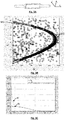
- the figure 3B represents for example in the form of a scatter plot the set of displacements obtained following an analysis of a series of 500 image acquisitions.
- Each displacement is represented by a circle whose abscissa is the component ⁇ x of displacement along the longitudinal axis X and whose ordinate is the coordinate of the reconstruction plane z j corresponding to the position of the particle at the start of the displacement.
- the points having the same ordinate correspond to displacements whose starting position is situated in a plane parallel to the image sensor situated at the distance z j from the latter.
- the taking into account of multiple acquisitions of images makes it possible to constitute data relating to the displacement, whose statistic is sufficient to determine or to adjust the parameters of the model.
- the cloud of points clearly shows a zone of high density which has a boomerang shape.
- the displacements At the center of the fluid chamber 15 (z j close to 35), the displacements have a maximum amplitude. At the borders of the fluid chamber 15 (z j close to 0 or z j close to 60), the displacements are lower, because of the presence of the walls of the fluidic chamber.
- the displacement model is three-dimensional, so as to take into account a fluid flow velocity distribution in a transverse plane YZ perpendicular to the flow axis X of the fluid, in particular because edge effects resulting from the walls of the fluidic chamber 15.
- the boomerang form is modeled by a polynomial of degree 3.
- the coefficients of this polynomial can be determined by a quadratic adjustment with respect to the measured data. It is thus possible to determine or refine the parameters of the model, on the basis of the images acquired. Thus, it is based on a parametric displacement model, the parameters of the model can be determined or updated by the experimental measurements.
- Step 220 Commitment validation During step 220, the potential displacements ⁇ determined during step 200 are compared with the displacement range defined during step 210. The displacements not included in the displacement range are considered invalid and are eliminated. . The displacements ⁇ v included in the range are validated.
- the displacement range is defined according to a plane ( ⁇ x , z j ), in which case the validation is carried out on the basis of a projection of each potential displacement vector according to this plane.
- Step 230 definition of the positions and / or the number of particles corresponding to valid displacements.
- a list of validated positions ( x , y , z ) ( t 1 ) of particles at the first instant and a list of positions ( x, y, z ) ( t 2 ) of particles validated at the second instant are then determined. This list is made considering that at the first instant and at the second instant, a particle is associated with only one displacement.
- Each list thus obtained makes it possible to estimate a position of the particles at the first instant, as well as a position of the particles at the second instant, as well as the number N of particles 10a circulating in the fluidic chamber 15.
- t i a particle at a time t i
- the instant t i represents a so-called current instant, the instants t i -1 and t i +1 being instants respectively anterior and posterior to the current instant.
- a first list is established positions torques between t i and t i -1.
- a second list of pairs of positions is established between instants t i and t i +1 .
- the list of particles at the current instant t i is obtained by performing the union of the first list and the second list, the duplicates being eliminated.
- Step 250 Threshold optimization
- a parameter that may be important for the implementation of the method is the threshold S used during step 180, to select or not particle positions.
- This threshold conditions the number of particles considered to establish the potential displacements.
- the figure 3C represents an evolution of the number of particles counted, by implementing the method described above, whose signal to noise ratio is greater than the value of the abscissa.
- Such a representation makes it possible to modify the threshold a posteriori, for example by fixing the value of the threshold at an optimum value corresponding to a flat part of the curve.
- the inventors consider that an optimal threshold corresponds to a flatter part of the curve, that is to say to a weak derivative, the derivative being calculated with respect to the value of the threshold.
- the optimal value of the threshold by implementing the process is 2.2 or 2.3. It is therefore possible to remove the posteriori particles having a signal-to-noise ratio below the threshold.
- the figure also shows an evolution of the number of particles N ' counted without considering a displacement, that is to say, based only on an image acquired at a given moment. It is observed that taking into account displacements makes it possible to reduce the number of particles counted, in particular when the threshold is weak.
- a fluid chamber as shown in FIG. figure 3A , vertically oriented.
- the test was carried out according to a configuration as described on the figure 1 the X axis, which propagates the particles, being vertical and downward.
- the potential displacement ⁇ is determined, the latter being represented in the form of circles having a ⁇ x coordinate along the X axis, a coordinated ⁇ z along the Z axis and a Coordinate ⁇ y along the Y axis.
- the potential displacements were obtained by taking into account the following sorting criteria: 0 ⁇ ⁇ x ⁇ 2.2 mm ; 0 ⁇ ⁇ y ⁇ 66 ⁇ m ; 0 ⁇ ⁇ z ⁇ 200 ⁇ m .
- the figure 3B illustrates these potential displacements in the form of a cloud of points in the plane ( ⁇ x , Z).
- a displacement model was taken into account, forming boundaries represented by the curves M1 and M2 plotted on the figure 3B . Displacements between these curves have been validated.
- the number N of particles has been counted, as a function of the signal to noise ratio threshold considered during step 180, the evolution of the number N of particles counted as a function of the signal ratio threshold S on noise being represented on the figure 3C .
- This figure also represents a number of particles N ' as a function of the signal to noise ratio threshold, without taking into account the displacement. It is found that beyond a certain threshold, the estimate without taking into account the displacement is reliable.
- the method may comprise a step 450 of adjustment of the signal to noise ratio threshold used, similarly to step 250 previously described.
- An advantage of this embodiment is to avoid the use of image sensors having an acquisition frequency too high. For example, when the time interval between the first instant and the second instant is 5 ms, the first embodiment, based on an acquisition of two successive images, would impose an acquisition rate of 200 images per second, which is not within the reach of conventional image sensors. This embodiment is therefore suitable for particles having high speeds.
- This embodiment was the subject of a second experimental test, the particles being polystyrene beads with a diameter of 2 ⁇ m moving in the air.
- the Figure 4B represents displacements as well as a modeled border.
- a limitation of this embodiment is that it only takes into account the particles present in the field of view of the image sensor at the two times considered.
- the inventors have estimated that by applying a weighting factor to each detected movement, the number of particles counted is more reliable.
- the weighting factor for each displacement ⁇ k is determined according to a probabilistic approach.
- K denotes the number of validated displacements ⁇ k , each displacement having for coordinates A X k and ⁇ Y k
- each type of particle may have a displacement, said particulate displacement, relative to the fluid, which is specific to it.
- the particle displacement can be induced by a property of the particle, conditioning the displacement of the particle with respect to the fluid.
- the particle then moves in the fluid under the effect of a force dependent on said property, for example under the effect of a field to which the particle is subjected.
- It can for example be an electric field, or magnetic, in which case a particle is subjected to a force dependent on its charge. It can also act of a gravitational field, in which case the particle moves with respect to the fluid according to its mass.
- a particulate particle displacement model with respect to the fluid, a parameter of which is said property of the particle.
- the particle displacement of each particle is preferably oriented in an orientation not parallel to the direction of flow of the fluid, but this condition is not necessary. It is optimal for the particle displacement to be perpendicular to the flow direction of the fluid.
- a particle displacement model corresponding to a predetermined value of the property can be taken into account. Then, for each particle, a difference ⁇ is determined with respect to this model. The particles can then be classified according to the difference ⁇ , with respect to the particle displacement model, which has been assigned to them. The particles are then classified according to their particle displacement. Particles for which the deviation is zero have a property corresponding to the predetermined value. The property of the other particles depends on the difference calculated for each one of them.
- a third experimental test was carried out to implement this variant, using polystyrene beads of 1 .mu.m diameter and 2 .mu.m diameter.
- the fluid chamber was kept arranged so that the particles were entrained by horizontally circulating air, the flow axis X being horizontal.
- the experimental device is represented on the Figure 1A , the XZ plane being a horizontal plane.
- the particles were driven horizontally by the carrier fluid, in this case air, along the horizontal axis X. They suffered the effect of gravity, along a vertical axis Y, perpendicular to the flow axis .
- the dimensions of the fluid chamber 15 were 10 mm and 20 mm respectively along the Z and Y axes.
- the fluid chamber had, in a YZ plane, a rectangular section of dimensions 9.6 mm ⁇ 20 mm.
- the property of each particle considered is the aerodynamic diameter, corresponding to the product of the diameter of a particle by the square root of its density.
- ⁇ Y is respectively equal to 12.4 and 31 ⁇ m, ie 5.6 and 14.1 pixels, for the first type and the second type of particles.
- a displacement is considered as potential when the signal-to-noise ratio associated with the two positions, defining the displacement, is similar. It is then possible to assign a signal-to-noise ratio S ⁇ to each displacement ⁇ , this ratio being obtained by averaging the signal-to-noise ratios respectively associated with each position forming the displacement.
- the signal to noise ratio S ⁇ displacements of the first type of particle is less than the signal to noise ratio of the displacements of the second type of particles (2 .mu.m particle size).
- the displacement, along the vertical axis Y, of the first type of particles is less than the displacement along the same axis of the second type of particles.
- the displacements associated with the first type of particle have a signal-to-noise ratio S ⁇ less than the displacements associated with the second type of particles.
- This variant makes it possible to count particles according to a property, such as mass, load, aerodynamic diameter. It can also be used to discriminate bacteria according to their motility. Staphylococci bacteria (non-motile that follow the fluid) can then be discriminated from bacteria of the Escherichia coli type (motiles, which move relative to the fluid).
- the images are acquired by an image sensor 20 placed in a lensless imaging configuration, with no image forming optics disposed between the image sensor and the image sensor. fluidic chamber.
- a device allows a determination of three-dimensional positions of particles using a two-dimensional image sensor, by implementing an inexpensive instrumentation.
- Such a device is therefore particularly suitable for implementing the invention.
- the invention applies to other imaging configurations for obtaining particle positions at two successive times, and in particular three-dimensional positions.
- the embodiments described above apply to a defocused image sensor, forming a defocused image of the sample, according to the known principle of digital holographic microscopes. The advantage is to be able to observe smaller particles, to the detriment of a reduced field of view.
- the invention can be applied to the detection of solid particles in the air, for example pollutants or dust, but also to the detection of particles, in particular biological particles, in a liquid. It will find applications in applications related to fluid control, for industry, the environment, health or agribusiness.
Applications Claiming Priority (1)
| Application Number | Priority Date | Filing Date | Title |
|---|---|---|---|
| FR1663475A FR3061297B1 (fr) | 2016-12-28 | 2016-12-28 | Procede de comptage et de caracterisation de particules dans un fluide en mouvement |
Publications (2)
| Publication Number | Publication Date |
|---|---|
| EP3343201A1 true EP3343201A1 (de) | 2018-07-04 |
| EP3343201B1 EP3343201B1 (de) | 2023-08-09 |
Family
ID=59031016
Family Applications (1)
| Application Number | Title | Priority Date | Filing Date |
|---|---|---|---|
| EP17210133.9A Active EP3343201B1 (de) | 2016-12-28 | 2017-12-22 | Zähl- und charakterisierungsverfahren von teilchen in einem fluid in bewegung, und gerät |
Country Status (3)
| Country | Link |
|---|---|
| US (1) | US10467764B2 (de) |
| EP (1) | EP3343201B1 (de) |
| FR (1) | FR3061297B1 (de) |
Families Citing this family (9)
| Publication number | Priority date | Publication date | Assignee | Title |
|---|---|---|---|---|
| WO2018227193A1 (en) * | 2017-06-09 | 2018-12-13 | miDiagnostics NV | Systems and methods for counting particles |
| JP6971842B2 (ja) * | 2017-12-28 | 2021-11-24 | キオクシア株式会社 | 計測装置および計測方法 |
| FR3082944A1 (fr) | 2018-06-20 | 2019-12-27 | Commissariat A L'energie Atomique Et Aux Energies Alternatives | Procede d'observation d'un echantillon par imagerie sans lentille, avec prise en compte d'une dispersion spatiale dans l'echantillon |
| EP3839479B1 (de) * | 2019-12-20 | 2024-04-03 | IMEC vzw | Vorrichtung zum nachweis von partikeln in der luft |
| EP3839636B1 (de) | 2019-12-20 | 2024-03-13 | Imec VZW | Vorrichtung zum nachweis von partikeln in der luft |
| US11828696B2 (en) | 2020-12-16 | 2023-11-28 | Caterpillar Inc. | System and method for processing data from a particle monitoring sensor |
| CN114219858A (zh) * | 2021-11-26 | 2022-03-22 | 华南理工大学 | 一种微粒的三维快速定位方法 |
| FR3130971A1 (fr) * | 2021-12-17 | 2023-06-23 | Commissariat A L'energie Atomique Et Aux Energies Alternatives | Procédé et appareil de sélection, détection, comptage et identification de pollens et/ou de moisissures initialement en suspension dans l’air atmosphérique. |
| US11506588B1 (en) * | 2022-05-06 | 2022-11-22 | HavaTell Inc. | Air quality meter |
Citations (2)
| Publication number | Priority date | Publication date | Assignee | Title |
|---|---|---|---|---|
| WO2008090330A1 (en) * | 2007-01-22 | 2008-07-31 | Cancer Research Technology Ltd | Detecting objects |
| FR3031180A1 (fr) * | 2014-12-30 | 2016-07-01 | Commissariat Energie Atomique | Methode et dispositf de controle de la position d'une particule transparente par pile d'images holographiques |
Family Cites Families (3)
| Publication number | Priority date | Publication date | Assignee | Title |
|---|---|---|---|---|
| WO2008132995A1 (ja) * | 2007-04-12 | 2008-11-06 | The University Of Electro-Communications | 粒子計測装置、及び粒径計測装置 |
| JP5478814B2 (ja) * | 2007-06-05 | 2014-04-23 | 株式会社東芝 | 超音波診断装置及び超音波による速度測定方法 |
| US8994945B2 (en) * | 2011-10-27 | 2015-03-31 | Fluid Imaging Technologies, Inc. | Method of treatment analysis with particle imaging |
-
2016
- 2016-12-28 FR FR1663475A patent/FR3061297B1/fr active Active
-
2017
- 2017-12-22 EP EP17210133.9A patent/EP3343201B1/de active Active
- 2017-12-28 US US15/856,679 patent/US10467764B2/en active Active
Patent Citations (2)
| Publication number | Priority date | Publication date | Assignee | Title |
|---|---|---|---|---|
| WO2008090330A1 (en) * | 2007-01-22 | 2008-07-31 | Cancer Research Technology Ltd | Detecting objects |
| FR3031180A1 (fr) * | 2014-12-30 | 2016-07-01 | Commissariat Energie Atomique | Methode et dispositf de controle de la position d'une particule transparente par pile d'images holographiques |
Non-Patent Citations (1)
| Title |
|---|
| PASQUALE MEMMOLO ET AL: "Twin-beams digital holography for 3D tracking and quantitative phase-contrast microscopy in microfluidics", OPTICS EXPRESS, vol. 19, no. 25, 5 December 2011 (2011-12-05), pages 25833, XP055145579, ISSN: 1094-4087, DOI: 10.1364/OE.19.025833 * |
Also Published As
| Publication number | Publication date |
|---|---|
| US10467764B2 (en) | 2019-11-05 |
| EP3343201B1 (de) | 2023-08-09 |
| US20180189963A1 (en) | 2018-07-05 |
| FR3061297A1 (fr) | 2018-06-29 |
| FR3061297B1 (fr) | 2019-05-24 |
Similar Documents
| Publication | Publication Date | Title |
|---|---|---|
| EP3343201B1 (de) | Zähl- und charakterisierungsverfahren von teilchen in einem fluid in bewegung, und gerät | |
| EP3274689B1 (de) | Verfahren und vorrichtung zur analyse von partikeln | |
| EP3274694B1 (de) | Verfahren zur bestimmung des zustandes einer zelle | |
| EP3234550B1 (de) | Verfahren zur identifizierung biologischer partikel mit stapeln von defokussierten holografischen bildern | |
| EP3465153B1 (de) | Vorrichtung und verfahren zur erfassung eines partikels, das in einer probe enthalten ist | |
| EP3218769B1 (de) | Analyseverfahren mit holographischer bestimmung einer position eines biologischen partikels | |
| EP2556164B1 (de) | Verfahren für den nachweis von clustern aus biologischen partikeln | |
| WO2017178723A1 (fr) | Procédé de caractérisation holographique d'une particule dans un échantillon | |
| EP3584560A1 (de) | Verfahren zur beobachtung einer probe mit linsenloser bildgebung unter berücksichtigung einer räumlichen dispersion in der probe | |
| EP3640743A1 (de) | Beobachtungsverfahren einer probe | |
| EP2356429B1 (de) | Vorrichtung zur analyse eines mehrphasengemischs über einen durch das gemisch zurückgestreuten lichtstrahl | |
| EP3637194B1 (de) | Verfahren zu bestimmung der parameter eines teilchens | |
| EP3520022A1 (de) | Verfahren zur zählung von leukozyten in einer probe | |
| EP3754431A1 (de) | Holografisches rekonstruktionsverfahren | |
| EP3114459B1 (de) | Verfahren und system zur charakterisierung eines adhäsionstatus von partikeln wie etwa zellen | |
| EP4232946A1 (de) | Verfahren zur klassifizierung einer sequenz von eingabebildern, die ein teilchen in einer probe im laufe der zeit darstellen | |
| EP2649430B1 (de) | Verfahren und vorrichtung zur charakterisierung der internen dynamik einer materialprobe in gegenwart einer starrkörperverschiebung | |
| FR3115387A1 (fr) | Procédé de classification d’une image d’entrée représentant une particule dans un échantillon | |
| EP3735578A1 (de) | Verfahren und system zur optischen inspektion eines substrats | |
| FR3082943A1 (fr) | Procede de comptage de particules de petite taille dans un echantillon | |
| EP3724725A1 (de) | Verfahren zur kalibrierung einer analysevorrichtung und zugehörige vorrichtung | |
| EP3617646B1 (de) | Messmethode der linienrauheit eines liniennetzes durch beugung von röntgenstrahlen | |
| EP3995991A2 (de) | Verfahren zur erfassung eines zellulären ereignisses | |
| FR3027112A1 (fr) | Procede de caracterisation d'un champ electromagnetique genere par l'interaction d'une onde electromagnetique avec une structure photonique et/ou plasmonique |
Legal Events
| Date | Code | Title | Description |
|---|---|---|---|
| PUAI | Public reference made under article 153(3) epc to a published international application that has entered the european phase |
Free format text: ORIGINAL CODE: 0009012 |
|
| STAA | Information on the status of an ep patent application or granted ep patent |
Free format text: STATUS: REQUEST FOR EXAMINATION WAS MADE |
|
| 17P | Request for examination filed |
Effective date: 20171222 |
|
| AK | Designated contracting states |
Kind code of ref document: A1 Designated state(s): AL AT BE BG CH CY CZ DE DK EE ES FI FR GB GR HR HU IE IS IT LI LT LU LV MC MK MT NL NO PL PT RO RS SE SI SK SM TR |
|
| AX | Request for extension of the european patent |
Extension state: BA ME |
|
| RIN1 | Information on inventor provided before grant (corrected) |
Inventor name: ROUSIER, RODRIGUE Inventor name: ELVIRA, DAVID Inventor name: JOLY, PIERRE |
|
| STAA | Information on the status of an ep patent application or granted ep patent |
Free format text: STATUS: EXAMINATION IS IN PROGRESS |
|
| 17Q | First examination report despatched |
Effective date: 20210510 |
|
| STAA | Information on the status of an ep patent application or granted ep patent |
Free format text: STATUS: EXAMINATION IS IN PROGRESS |
|
| GRAP | Despatch of communication of intention to grant a patent |
Free format text: ORIGINAL CODE: EPIDOSNIGR1 |
|
| STAA | Information on the status of an ep patent application or granted ep patent |
Free format text: STATUS: GRANT OF PATENT IS INTENDED |
|
| INTG | Intention to grant announced |
Effective date: 20230309 |
|
| GRAS | Grant fee paid |
Free format text: ORIGINAL CODE: EPIDOSNIGR3 |
|
| GRAA | (expected) grant |
Free format text: ORIGINAL CODE: 0009210 |
|
| STAA | Information on the status of an ep patent application or granted ep patent |
Free format text: STATUS: THE PATENT HAS BEEN GRANTED |
|
| AK | Designated contracting states |
Kind code of ref document: B1 Designated state(s): AL AT BE BG CH CY CZ DE DK EE ES FI FR GB GR HR HU IE IS IT LI LT LU LV MC MK MT NL NO PL PT RO RS SE SI SK SM TR |
|
| REG | Reference to a national code |
Ref country code: GB Ref legal event code: FG4D Free format text: NOT ENGLISH |
|
| REG | Reference to a national code |
Ref country code: CH Ref legal event code: EP |
|
| REG | Reference to a national code |
Ref country code: DE Ref legal event code: R096 Ref document number: 602017072402 Country of ref document: DE |
|
| REG | Reference to a national code |
Ref country code: IE Ref legal event code: FG4D Free format text: LANGUAGE OF EP DOCUMENT: FRENCH |
|
| REG | Reference to a national code |
Ref country code: LT Ref legal event code: MG9D |
|
| REG | Reference to a national code |
Ref country code: NL Ref legal event code: MP Effective date: 20230809 |
|
| REG | Reference to a national code |
Ref country code: AT Ref legal event code: MK05 Ref document number: 1598061 Country of ref document: AT Kind code of ref document: T Effective date: 20230809 |
|
| PG25 | Lapsed in a contracting state [announced via postgrant information from national office to epo] |
Ref country code: GR Free format text: LAPSE BECAUSE OF FAILURE TO SUBMIT A TRANSLATION OF THE DESCRIPTION OR TO PAY THE FEE WITHIN THE PRESCRIBED TIME-LIMIT Effective date: 20231110 |
|
| PGFP | Annual fee paid to national office [announced via postgrant information from national office to epo] |
Ref country code: GB Payment date: 20231221 Year of fee payment: 7 |
|
| PG25 | Lapsed in a contracting state [announced via postgrant information from national office to epo] |
Ref country code: IS Free format text: LAPSE BECAUSE OF FAILURE TO SUBMIT A TRANSLATION OF THE DESCRIPTION OR TO PAY THE FEE WITHIN THE PRESCRIBED TIME-LIMIT Effective date: 20231209 |
|
| PG25 | Lapsed in a contracting state [announced via postgrant information from national office to epo] |
Ref country code: SE Free format text: LAPSE BECAUSE OF FAILURE TO SUBMIT A TRANSLATION OF THE DESCRIPTION OR TO PAY THE FEE WITHIN THE PRESCRIBED TIME-LIMIT Effective date: 20230809 Ref country code: RS Free format text: LAPSE BECAUSE OF FAILURE TO SUBMIT A TRANSLATION OF THE DESCRIPTION OR TO PAY THE FEE WITHIN THE PRESCRIBED TIME-LIMIT Effective date: 20230809 Ref country code: PT Free format text: LAPSE BECAUSE OF FAILURE TO SUBMIT A TRANSLATION OF THE DESCRIPTION OR TO PAY THE FEE WITHIN THE PRESCRIBED TIME-LIMIT Effective date: 20231211 Ref country code: NO Free format text: LAPSE BECAUSE OF FAILURE TO SUBMIT A TRANSLATION OF THE DESCRIPTION OR TO PAY THE FEE WITHIN THE PRESCRIBED TIME-LIMIT Effective date: 20231109 Ref country code: NL Free format text: LAPSE BECAUSE OF FAILURE TO SUBMIT A TRANSLATION OF THE DESCRIPTION OR TO PAY THE FEE WITHIN THE PRESCRIBED TIME-LIMIT Effective date: 20230809 Ref country code: LV Free format text: LAPSE BECAUSE OF FAILURE TO SUBMIT A TRANSLATION OF THE DESCRIPTION OR TO PAY THE FEE WITHIN THE PRESCRIBED TIME-LIMIT Effective date: 20230809 Ref country code: LT Free format text: LAPSE BECAUSE OF FAILURE TO SUBMIT A TRANSLATION OF THE DESCRIPTION OR TO PAY THE FEE WITHIN THE PRESCRIBED TIME-LIMIT Effective date: 20230809 Ref country code: IS Free format text: LAPSE BECAUSE OF FAILURE TO SUBMIT A TRANSLATION OF THE DESCRIPTION OR TO PAY THE FEE WITHIN THE PRESCRIBED TIME-LIMIT Effective date: 20231209 Ref country code: HR Free format text: LAPSE BECAUSE OF FAILURE TO SUBMIT A TRANSLATION OF THE DESCRIPTION OR TO PAY THE FEE WITHIN THE PRESCRIBED TIME-LIMIT Effective date: 20230809 Ref country code: GR Free format text: LAPSE BECAUSE OF FAILURE TO SUBMIT A TRANSLATION OF THE DESCRIPTION OR TO PAY THE FEE WITHIN THE PRESCRIBED TIME-LIMIT Effective date: 20231110 Ref country code: FI Free format text: LAPSE BECAUSE OF FAILURE TO SUBMIT A TRANSLATION OF THE DESCRIPTION OR TO PAY THE FEE WITHIN THE PRESCRIBED TIME-LIMIT Effective date: 20230809 Ref country code: AT Free format text: LAPSE BECAUSE OF FAILURE TO SUBMIT A TRANSLATION OF THE DESCRIPTION OR TO PAY THE FEE WITHIN THE PRESCRIBED TIME-LIMIT Effective date: 20230809 |
|
| PGFP | Annual fee paid to national office [announced via postgrant information from national office to epo] |
Ref country code: FR Payment date: 20231221 Year of fee payment: 7 Ref country code: DE Payment date: 20231219 Year of fee payment: 7 |
|
| PG25 | Lapsed in a contracting state [announced via postgrant information from national office to epo] |
Ref country code: PL Free format text: LAPSE BECAUSE OF FAILURE TO SUBMIT A TRANSLATION OF THE DESCRIPTION OR TO PAY THE FEE WITHIN THE PRESCRIBED TIME-LIMIT Effective date: 20230809 |
|
| PG25 | Lapsed in a contracting state [announced via postgrant information from national office to epo] |
Ref country code: ES Free format text: LAPSE BECAUSE OF FAILURE TO SUBMIT A TRANSLATION OF THE DESCRIPTION OR TO PAY THE FEE WITHIN THE PRESCRIBED TIME-LIMIT Effective date: 20230809 |
|
| PG25 | Lapsed in a contracting state [announced via postgrant information from national office to epo] |
Ref country code: SM Free format text: LAPSE BECAUSE OF FAILURE TO SUBMIT A TRANSLATION OF THE DESCRIPTION OR TO PAY THE FEE WITHIN THE PRESCRIBED TIME-LIMIT Effective date: 20230809 Ref country code: RO Free format text: LAPSE BECAUSE OF FAILURE TO SUBMIT A TRANSLATION OF THE DESCRIPTION OR TO PAY THE FEE WITHIN THE PRESCRIBED TIME-LIMIT Effective date: 20230809 Ref country code: ES Free format text: LAPSE BECAUSE OF FAILURE TO SUBMIT A TRANSLATION OF THE DESCRIPTION OR TO PAY THE FEE WITHIN THE PRESCRIBED TIME-LIMIT Effective date: 20230809 Ref country code: EE Free format text: LAPSE BECAUSE OF FAILURE TO SUBMIT A TRANSLATION OF THE DESCRIPTION OR TO PAY THE FEE WITHIN THE PRESCRIBED TIME-LIMIT Effective date: 20230809 Ref country code: DK Free format text: LAPSE BECAUSE OF FAILURE TO SUBMIT A TRANSLATION OF THE DESCRIPTION OR TO PAY THE FEE WITHIN THE PRESCRIBED TIME-LIMIT Effective date: 20230809 Ref country code: CZ Free format text: LAPSE BECAUSE OF FAILURE TO SUBMIT A TRANSLATION OF THE DESCRIPTION OR TO PAY THE FEE WITHIN THE PRESCRIBED TIME-LIMIT Effective date: 20230809 Ref country code: SK Free format text: LAPSE BECAUSE OF FAILURE TO SUBMIT A TRANSLATION OF THE DESCRIPTION OR TO PAY THE FEE WITHIN THE PRESCRIBED TIME-LIMIT Effective date: 20230809 |