EP3343191A1 - Magnetostrictive sensor - Google Patents
Magnetostrictive sensor Download PDFInfo
- Publication number
- EP3343191A1 EP3343191A1 EP16851919.7A EP16851919A EP3343191A1 EP 3343191 A1 EP3343191 A1 EP 3343191A1 EP 16851919 A EP16851919 A EP 16851919A EP 3343191 A1 EP3343191 A1 EP 3343191A1
- Authority
- EP
- European Patent Office
- Prior art keywords
- substrate
- outer peripheral
- peripheral surface
- plating film
- base portion
- Prior art date
- Legal status (The legal status is an assumption and is not a legal conclusion. Google has not performed a legal analysis and makes no representation as to the accuracy of the status listed.)
- Granted
Links
Images



Classifications
-
- G—PHYSICS
- G01—MEASURING; TESTING
- G01L—MEASURING FORCE, STRESS, TORQUE, WORK, MECHANICAL POWER, MECHANICAL EFFICIENCY, OR FLUID PRESSURE
- G01L3/00—Measuring torque, work, mechanical power, or mechanical efficiency, in general
- G01L3/02—Rotary-transmission dynamometers
- G01L3/04—Rotary-transmission dynamometers wherein the torque-transmitting element comprises a torsionally-flexible shaft
- G01L3/10—Rotary-transmission dynamometers wherein the torque-transmitting element comprises a torsionally-flexible shaft involving electric or magnetic means for indicating
- G01L3/101—Rotary-transmission dynamometers wherein the torque-transmitting element comprises a torsionally-flexible shaft involving electric or magnetic means for indicating involving magnetic or electromagnetic means
- G01L3/102—Rotary-transmission dynamometers wherein the torque-transmitting element comprises a torsionally-flexible shaft involving electric or magnetic means for indicating involving magnetic or electromagnetic means involving magnetostrictive means
-
- G—PHYSICS
- G01—MEASURING; TESTING
- G01L—MEASURING FORCE, STRESS, TORQUE, WORK, MECHANICAL POWER, MECHANICAL EFFICIENCY, OR FLUID PRESSURE
- G01L3/00—Measuring torque, work, mechanical power, or mechanical efficiency, in general
- G01L3/02—Rotary-transmission dynamometers
- G01L3/04—Rotary-transmission dynamometers wherein the torque-transmitting element comprises a torsionally-flexible shaft
- G01L3/10—Rotary-transmission dynamometers wherein the torque-transmitting element comprises a torsionally-flexible shaft involving electric or magnetic means for indicating
Definitions
- the present teaching relates to a magnetostrictive sensor.
- a magnetostrictive sensor has been conventionally used for detecting a torque acting on a component of equipment or detecting a load acting on the component.
- a known configuration example of the magnetostrictive sensor includes: a columnar substrate having an outer peripheral surface on which a magnetostrictive portion is provided; and a detection coil that generates a magnetic flux passing through the magnetostrictive portion.
- the magnetostrictive sensor having such a configuration as a torque sensor, when a force in a rotation direction is applied to the substrate, a tensile stress or a compressive stress occurs in the magnetostrictive portion. Accordingly, the magnetic permeability of the magnetostrictive portion changes.
- the torque sensor detects a change in the magnetic permeability of the magnetostrictive portion using the detection coil to thereby detect a force acting on the substrate.
- an amorphous thin strap or a plating film can be used as the magnetostrictive portions.
- the sensitivity of the magnetostrictive sensor can be increased.
- the amorphous thin strap needs to be bonded to the outer peripheral surface of the substrate with an adhesive. To accurately bond the amorphous thin strap to the outer peripheral surface of the substrate, the adhesive needs to be uniformly applied onto the outer peripheral surface of the substrate. It is, however, difficult to uniformly apply the adhesive onto the outer peripheral surface of the substrate.
- the adhesive is likely to extend off between the amorphous thin strap and the substrate in bonding the amorphous thin strap to the substrate. In this case, a process for removing the excess adhesive is needed.
- the amorphous thin strap is thin, it is difficult to use the amorphous thin strap with an industrial robot. In view of these circumstances, in the case of using the amorphous thin strap as the magnetostrictive portion, it is difficult to enhance productivity.
- the use of a plating film as the magnetostrictive portion is conceivable.
- the substrate is immersed in a plating solution with a predetermined portion of the substrate masked with a masking member. Thereafter, a current is caused to flow in the plating solution so that a plating film is formed in an unmasked portion of the substrate.
- Patent Document 1 Japanese Patent No. 4936969
- plating films e.g., distribution of film thickness
- outputs of the magnetostrictive sensors also vary.
- plating films need to be formed with high reproducibility in order to prevent variations in the shape of the plating films. In this case, the masking needs to be controlled with high accuracy.
- the inventors of the present teaching studied the formation of a plating film by electroplating and found that, in some cases, the thickness of the plating film increases in an end portion thereof (a portion to come into contact with a masking member during the formation). It was found that in such cases, a magnetic flux generated by, for example, a detection coil and passing through the end portion of the plating film become nonuniform, resulting in the occurrence of variations in outputs of magnetostrictive sensors.
- a variation also occurs in thickness distribution of the plating film in the circumferential direction of the substrate.
- the amount of a magnetic flux passing through the plating film varies depending on a rotation angle of the substrate relative to the detection coil, for example. Accordingly, even in a state where a force in the rotation direction does not act on the substrate (i.e., under no load), the value of a current flowing in the detection coil varies depending on the rotation angle of the substrate. Consequently, an output of a magnetostrictive sensor under no load varies depending on the rotation angle of the substrate, and thus, accuracy in detection by the magnetostrictive sensor decreases.
- the inventors intensively studied the thickness of the plating film to find that the thickness of the end portion of the plating film increases and/or thickness distribution varies in the end portion of the plating film in a case where the masking is insufficiently controlled in forming the plating film.
- the thickness of the end portion of the plating film can be reduced by causing a portion of the outer peripheral surface of the substrate where the end portion of the plating film is located to tilt relative to the shaft center of the substrate.
- the inventors arrived at a configuration of a magnetostrictive sensor described below.
- a magnetostrictive sensor includes: a columnar or tubular substrate; and a plating film disposed on an outer peripheral surface of the substrate, wherein the substrate includes a first base portion, a second base portion having a diameter larger than a diameter of the first base portion, and a tilt portion disposed between the first base portion and the second base portion in an axial direction of the substrate and connecting the first base portion and the second base portion, the first base portion has an outer peripheral surface parallel to a shaft center of the substrate in a cross-section including the shaft center and extending in the axial direction of the substrate, the tilt portion has an outer peripheral surface that is a slope tilted relative to the shaft center in the cross-section, the plating film is formed on the outer peripheral surface of the first base portion and on the slope in such a manner that one end of the plating film in the axial direction is located on the slope, and the plating film has a thickness on the slope smaller than a thickness of the plating film on the outer peripheral surface of the first base portion.
- a magnetostrictive sensor according to an embodiment of the present teaching can obtain both enhancement of productivity and reduction of variations in outputs.
- a magnetostrictive sensor according to an embodiment of the present teaching will now be described.
- a magnetostrictive torque sensor will be hereinafter described as a magnetostrictive sensor according to an embodiment of the present teaching.
- FIG. 1 is a front view illustrating a schematic configuration of a torque sensor 10 according to an embodiment of the present teaching.
- FIG. 2 is a vertical cross-sectional view illustrating the schematic configuration of the torque sensor 10 in cross-section.
- the torque sensor 10 includes a magnetostrictive unit 10a and a detection unit 10b.
- Each of the magnetostrictive unit 10a and the detection unit 10b has a substantially tubular shape.
- the magnetostrictive unit 10a is rotatably inserted in the detection unit 10b, which will be described in detail later.
- a torque acts on a substrate 12 described later of the magnetostrictive unit 10a so that the magnetic permeability of a plating film 14 (see FIG. 3 ) described later of the magnetostrictive unit 10a thereby changes.
- the change in the magnetic permeability of the plating film 14 is detected by a pair of detection coils 42a and 42b described later of the detection unit 10b. In this manner, the torque acting on the substrate 12 is detected.
- the torque sensor 10 can be used, for example, as a torque sensor for detecting a pedaling force in a driving device of an electric motor-assisted bicycle.
- FIG. 3 is a front view illustrating the magnetostrictive unit 10a.
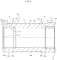
- FIG. 4 is a vertical cross-sectional view illustrating the magnetostrictive unit 10a in cross-section.
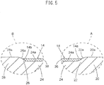
- FIG. 5 shows enlarged views illustrating portions A and B surrounded by broken lines in FIG. 4 in an enlarged manner.
- the magnetostrictive unit 10a includes the tubular substrate 12, the plating film 14 disposed on the outer peripheral surface of the substrate 12, and an annular bearing member 16 fitted in an end portion of the substrate 12.
- FIG. 2 does not show the plating film 14 to simplify the illustration.
- the substrate 12 includes a flange portion 18, a support portion 20, a tilt portion 22, a plating portion 24 (first base portion), a tilt portion 26, a support portion 28, a holding portion 30, and a flange portion 32, from one end 12a to the other end 12b of the substrate 12 in an axial direction.
- a spline groove is formed on the outer peripheral surface of the flange portion 18 to extend in the axial direction of the substrate 12.
- the flange portion 18 projects from the detection unit 10b in the axial direction of the detection unit 10b in a state where the magnetostrictive unit 10a is inserted in the detection unit 10b.
- an outer peripheral surface 20a of the support portion 20 is a surface parallel to a shaft center of the substrate 12 (see a chain line in FIG. 4 ) in a cross-section of the substrate 12 including the shaft center and extending in the axial direction of the substrate 12 (hereinafter referred to as a vertical cross-section of the substrate 12).
- each of an outer peripheral surface 24a of the plating portion 24 and an outer peripheral surface 28a of the support portion 28 is a surface parallel to the shaft center of the substrate 12 in the vertical cross-section of the substrate 12.
- the plating portion 24 has a diameter smaller than the diameter of the support portion 20.
- the plating portion 24 has a diameter smaller than the diameter of the support portion 28.
- each of the support portions 20 and 28 correspond to a second base portion, and the outer peripheral surface 24a corresponds to the outer peripheral surface of the first base portion.
- each of the support portions 20 and 28 has a diameter smaller than the diameter of the flange portion 18 (spline outer diameter).
- the tilt portion 22 is disposed between the support portion 20 and the plating portion 24 in the axial direction of the substrate 12, and connects the support portion 20 and the plating portion 24 to each other.
- An outer peripheral surface 22a of the tilt portion 22 is a slope tilted relative to the shaft center of the substrate 12 in the vertical cross-section of the substrate 12.
- the diameter of the tilt portion 22 gradually decreases from the support portion 20 toward the plating portion 24. Accordingly, in the vertical cross-section of the substrate 12, the outer peripheral surface 22a tilts relative to the shaft center of the substrate 12 radially inward in the substrate 12 from the outer peripheral surface 20a toward the outer peripheral surface 24a.
- the tilt portion 26 is disposed between the support portion 28 and the plating portion 24 in the axial direction of the substrate 12, and connects the support portion 28 and the plating portion 24 to each other.
- An outer peripheral surface 26a of the tilt portion 26 is a slope tilted relative to the shaft center of the substrate 12 in the vertical cross-section of the substrate 12.
- the diameter of the tilt portion 26 gradually decreases from the support portion 28 toward the plating portion 24. Accordingly, in the vertical cross-section, the outer peripheral surface 26a tilts relative to the shaft center of the substrate 12 radially inward in the substrate 12 from the outer peripheral surface 28a toward the outer peripheral surface 24a.
- a connection portion between the outer peripheral surface 22a and the outer peripheral surface 20a and a connection portion between the outer peripheral surface 22a and the outer peripheral surface 24a have curved shapes in the vertical cross-section of the substrate 12.
- a connection portion between the outer peripheral surface 26a and the outer peripheral surface 28a and a connection portion between the outer peripheral surface 26a and the outer peripheral surface 24a have curved shapes in the vertical cross-section of the substrate 12.
- the holding portion 30 has a diameter smaller than each of the diameter of the support portion 28 and the diameter of the flange portion 32. In this manner, a groove 30a is formed between the support portion 28 and the flange portion 32.
- a spline groove 34 is formed on the inner peripheral surface of the substrate 12 to extend in the axial direction of the substrate 12.
- the spline groove 34 is simplified.
- the spline groove 34 is formed closer to the other end 12b than the center of the substrate 12 in the axial direction of the substrate 12.
- a front end 34a of the spline groove 34 (an end toward the other end 12b in the axial direction of the substrate 12) is located closer to the inside of the substrate 12 than the other end 12b in the axial direction of the substrate 12. That is, the spline groove 34 is formed closer to the inside of the substrate 12 than the other end 12b in the axial direction of the substrate 12.
- the thickness of the substrate 12 is larger in a center portion of the substrate 12 than in end portions of the substrate 12 in the axial direction thereof.
- the thickness of the substrate 12 in portions facing a pair of detection coils 42a and 42b described later is larger than the thickness of end portions of the substrate 12.
- the substrate 12 is made of, for example, a metal material (e.g., chromium molybdenum steel).
- the substrate 12 is produced by, for example, forging and machining. Specifically, for example, first, a metal material cut out from a metal wire material to have a predetermined length is forged, and thereby, a hollow member is obtained. The spline groove 34 and the spline groove in the flange portion 18 described above are shaped by the forging. Next, the forged member is subjected to thermal refining (e.g., hardening and tempering), and then, the outer peripheral surface of the member is cut by machining (e.g., turning). In this manner, the outer peripheral surfaces 20a, 22a, 24a, 26a, and 28a having predetermined shapes are formed, and the substrate 12 is obtained.
- thermal refining e.g., hardening and tempering
- machining e.g., turning
- the plating film 14 is made of a magnetostrictive material (e.g., a Fe-Ni alloy) and functions as a magnetostrictive portion.
- the plating film 14 is formed by, for example, electroplating.
- the plating film 14 is formed on the outer peripheral surface 24a of the plating portion 24 and the outer peripheral surfaces 22a and 26a of the tilt portions 22 and 26 to have a tubular shape.
- one end 14a of the plating film 14 is located on the outer peripheral surface 22a, and the other end 14b of the plating film 14 is located on the outer peripheral surface 26a.
- the thickness of the plating film 14 on the outer peripheral surface 22a and the thickness of the plating film 14 on the outer peripheral surface 26a are smaller than the thickness of the plating film 14 on the outer peripheral surface 24a.
- the thickness of the plating film 14 on the outer peripheral surface 22a, the thickness of the plating film 14 on the outer peripheral surface 26a, and the thickness of the plating film 14 on the outer peripheral surface 24a respectively refer to an average thickness of the plating film 14 on the outer peripheral surface 22a, an average thickness of the plating film 14 on the outer peripheral surface 26a, and an average thickness of the plating film 14 on the outer peripheral surface 24a.
- the plating film 14 includes a magnetostrictive portion 36 and a magnetostrictive portion 38.
- the magnetostrictive portion 36 includes a plurality of slits 36a.
- the magnetostrictive portion 38 includes a plurality of slits 38a.
- the plurality of slits 36a are arranged at regular intervals in the circumferential direction of the substrate 12.
- the plurality of slits 38a are arranged at regular intervals in the circumferential direction of the substrate 12.
- the slits 36a When viewed from outside in the radial direction of the substrate 12, the slits 36a are tilted 45° relative to the shaft center of the substrate 12. When viewed from outside in the radial direction of the substrate 12, the slits 38a are tilted 45° in a direction different from the slits 36a relative to the shaft center of the substrate 12. That is, in this embodiment, the plurality of slits 36a and 38a are formed in the plating film 14 in such a manner that the slits 36a and the slits 38a intersect with each other perpendicularly.
- FIGS. 4 and 5 do not show the plurality of slits 36a and 38a.
- the bearing member 16 is made of, for example, a metal material.
- the bearing member 16 is press fitted in the substrate 12 from the one end 12a of the substrate 12.
- the detection unit 10b includes a bobbin 40, a pair of detection coils 42a and 42b, a connector 44, a case 46, a pair of protective plates 48a and 48b, and a circlip 50.
- the bobbin 40 is made of, for example, a resin material. With reference to FIG. 2 , the bobbin 40 has a substantially tubular shape. Specifically, the bobbin 40 includes a tubular portion 40a and a plurality of (four in this embodiment) flange portions 40b through 40e projecting from the outer peripheral surface of the tubular portion 40a outward in the radial direction of the tubular portion 40a. The flange portions 40b through 40e are arranged at intervals from one another in the axial direction of the tubular portion 40a.
- the detection coil 42a is wound around the tubular portion 40a between the flange portion 40b and the flange portion 40c.
- the detection coil 42b is wound around the tubular portion 40a between the flange portion 40d and the flange portion 40e.
- the detection coils 42a and 42b include welded layers.
- adjacent coil wires are fixed to each other by self-welding.
- the detection coils 42a and 42b may not include welded layers. In this case, adjacent coil wires may be fixed to each other with another technique such as impregnation.
- the flange portion 40b is provided with a plurality of terminals electrically connected to the detection coils 42a and 42b. To protect these terminals, a connector 44 is attached to the flange portion 40b. These plurality of terminals are electrically connected to terminals of an unillustrated control board.
- the control board is provided with an arithmetic circuit. The arithmetic circuit calculates a torque acting on the substrate 12 based on changes in the impedances of the detection coils 42a and 42b, for example.
- the case 46 is made of, for example, a metal material such as low-carbon steel.
- the case 46 has a tubular shape.
- the bobbin 40 is inserted in the case 46.
- the case 46 covers radially outsides of the detection coils 42a and 42b.
- one end portion of the case 46 has a plurality of substantially U-shaped through holes 46a.
- the formation of the through holes 46a forms substantially rectangular swaging portions 46b.
- the plurality of swaging portions 46b are formed at regular intervals in the circumferential direction of the case 46.
- the case 46 is fixed to the bobbin 40 by swaging using the plurality of swaging portions 46b.
- each of the protective plates 48a and 48b has an annular shape.
- Each of the protective plates 48a and 48b is made of, for example, a resin material.
- the protective plate 48a is disposed between one end surface of the bobbin 40 and the flange portion 18 of the substrate 12.
- the protective plate 48b is disposed between the other end surface of the bobbin 40 and the circlip 50.
- the protective plate 48a is provided to prevent abrasion of the one end surface of the bobbin 40.
- the protective plate 48a is provided to prevent abrasion of the other end surface of the bobbin 40.
- the circlip 50 has a substantially C-shape, and is fitted in the groove 30a of the substrate 12.
- the circlip 50 is made of a metal material.
- the circlip 50 is disposed to prevent the bobbin 40 and the protective plates 48a and 48b from moving in the axial direction of the substrate 12 relative to the substrate 12.
- the protective plate 48a is fitted in the substrate 12 from the other end 12b of the substrate 12, for example.
- the bobbin 40, the detection coils 42a and 42b, the connector 44, and the case 46 that are integrally formed are fitted in the substrate 12 from the other end 12b of the substrate 12.
- the protective plate 48b is fitted in the substrate 12 from the other end 12b of the substrate 12.
- the circlip 50 is fitted in the groove 30a. In this manner, attachment of the detection unit 10b to the magnetostrictive unit 10a is completed.
- the outer peripheral surface 20a of the support portion 20 and the outer peripheral surface 28a of the support portion 28 are rotatably supported on the inner peripheral surface of the bobbin 40.
- the bobbin 40 covers the plating film 14 from radially outside of the substrate 12 not to contact the plating film 14 (see FIG. 3 ).
- the detection coils 42a and 42b are disposed at positions facing the plating film 14 in the radial direction of the substrate 12. More specifically, in the radial direction of the substrate 12, the detection coil 42a is disposed at a position facing the magnetostrictive portion 36, and the detection coil 42b is disposed at a position facing the magnetostrictive portion 38.
- the substrate 12 is directly supported on the inner peripheral surface of the bobbin 40 as described above.
- the substrate 12 may be indirectly supported on the inner peripheral surface of the bobbin 40 with a ring-shaped bearing member or another member interposed therebetween.
- the torque sensor 10 can be used, for example, as a torque sensor for detecting a pedaling force in a driving device of an electric motor-assisted bicycle.
- a crank shaft 52 of the electric motor-assisted bicycle is inserted in the substrate 12.
- the crank shaft 52 is inserted in the substrate 12 in such a manner that a spline groove (not shown) formed on the outer peripheral surface of the crank shaft 52 and the spline groove 34 on the inner peripheral surface of the substrate 12 mesh with each other. In this manner, a torque can be transferred from the crank shaft 52 to the substrate 12.
- the flange portion 18 of the substrate 12 is, for example, connected to a chain sprocket (not shown) of the electric motor-assisted bicycle through a one-way clutch.
- the detection unit 10b (more specifically the bobbin 40, for example) is fixed to a housing of the driving device (not shown) by using an unillustrated fixing member.
- FIG. 6 is a view for describing an example of a method for forming the plating film 14.
- the method for forming the plating film 14 is not limited to the following examples, and the plating film 14 may be formed by using various known methods.
- an electrode 54 is disposed radially outside the substrate 12 in a plating solution, for example.
- Masking members 56 and 58 are used to mask outer peripheral surfaces (masking surfaces) 20a and 28a of the support portions 20 and 28.
- a front end portion of the masking member 56 projects toward the outer peripheral surface 22a relative to a connection portion between the outer peripheral surface 20a and the outer peripheral surface 22a.
- a front end portion of the masking member 58 projects toward the outer peripheral surface 26a relative to a connection portion between the outer peripheral surface 28a and the outer peripheral surface 26a.
- the flange portion 18, the holding portion 30, and the flange portion 32 are also masked with the masking members 56 and 58.
- a potential difference is generated between the electrode 54 and the substrate 12. Accordingly, a plating film 14 is formed on the outer peripheral surface of the substrate 12 by metal ions in the plating solution.
- the plating film 14 is formed on the outer peripheral surfaces 22a, 24a, and 26a.
- the tilt portion 22 is disposed between the plating portion 24 (first base portion) and the support portion (second base portion) 20, and is connected to the plating portion 24 and the support portion 20.
- the tilt portion 26 is disposed between the plating portion 24 (first base portion) and the support portion (second base portion) 28, and is connected to the plating portion 24 and the support portion 28.
- the plating portion 24 has a diameter smaller than the diameter of each of the support portions 20 and 28. The diameters of the tilt portions 22 and 26 gradually decrease from the support portions 20 and 28 toward the plating portion 24.
- a space that gradually narrows toward the support portion 20 is formed between the front end portion of the masking member 56 and the outer peripheral surface 22a.
- a space that gradually narrows toward the support portion 28 is formed between the front end portion of the masking member 58 and the outer peripheral surface 26a.
- the amount of metal ions supplied to the outer peripheral surfaces 22a and 26a decreases toward the support portions 20 and 28.
- the thickness of the plating film 14 formed on the outer peripheral surfaces 22a and 26a also decreases toward the support portions 20 and 28.
- the thicknesses of the end portions 14a and 14b of the plating film 14 can be easily made smaller than the thickness of the plating film 14 on the outer peripheral surface 24a of the plating portion 24.
- the thicknesses of the end portions 14a and 14b of the plating film 14 refer to averages of the thicknesses of the plating film 14 in the end portions 14a and 14b, respectively.
- the thickness of the plating film 14 on the outer peripheral surface 24a of the plating portion 24 refers to an average thickness of the plating film 14 on the outer peripheral surface 24a of the plating portion 24.
- the thicknesses of the end portions 14a and 14b of the plating film 14 are small as described above, in generating a magnetic flux by the detection coils 42a and 42b, for example, it is possible to reduce unevenness of magnetic fluxes passing through the end portions 14a and 14b.
- the thicknesses of the end portions 14a and 14b of the plating film 14 are small, even when the shape of the end portions 14a and 14b varies, it is possible to reduce variations in the amount of magnetic fluxes passing through the end portions 14a and 14b of the plating film 14 depending on the rotation angle of the substrate 12. In this manner, it is possible to reduce variations in the amount of the magnetic fluxes passing through the plating film 14 depending on the rotation angle of the substrate 12. As a result, an output of the torque sensor 10 can be stabilized.
- a connection portion between the outer peripheral surface 22a of the tilt portion 22 and the outer peripheral surface 20a of the support portion 20 has a curved shape in the vertical cross-section of the substrate 12.
- a connection portion between the outer peripheral surface 26a of the tilt portion 26 and the outer peripheral surface 28a of the support portion 28 has a curved shape in the vertical cross-section of the substrate 12.
- the burrs enlarged by plating might damage components (e.g., the bobbin 40) of the torque sensor 10.
- the connection portions have curved shapes in the vertical cross-section of the substrate 12, the occurrence of burrs in the connection portions in cutting the substrate 12 can be prevented. In this manner, damage of components of the torque sensor 10 can be prevented.
- the bobbin 40 covers the plating film 14 from radially outside of the substrate 12. Accordingly, the plating film 14 can be protected by the bobbin 40.
- the outer peripheral surfaces 20a and 28a are rotatably supported on the inner peripheral surface of the bobbin 40. In this manner, contact between the plating film 14 and the bobbin 40 can be prevented. Consequently, damage of the plating film 14 can be prevented.
- the diameter of the plating portion 24 (first base portion) is smaller than the diameters of the support portions (second base portion) 20 and 28.
- the shape of the substrate is not limited to the example described above.
- the diameter of the plating portion (first base portion) may be larger than the diameter of the support portion (second base portion).
- a torque sensor 60 having such a configuration will be briefly described below.
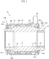
- FIG. 7 is a vertical cross-sectional view illustrating a schematic configuration of the torque sensor 60 according to another embodiment of the present teaching in cross-section.
- the torque sensor 60 includes a magnetostrictive unit 60a and a detection unit 60b.
- the torque sensor 60 will now be briefly described mainly for aspects different from the torque sensor 10 described above.
- FIG. 7 does not show a plating film 64 described later in order to simplify the illustration.
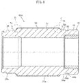
- FIG. 8 is a vertical cross-sectional view illustrating the magnetostrictive unit 60a in cross-section.
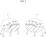
- FIG. 9 shows enlarged views illustrating portions C and D surrounded by broken lines in FIG. 8 in an enlarged manner.
- the magnetostrictive unit 60a is different from the magnetostrictive unit 10a described above in the following aspects.
- the magnetostrictive unit 60a includes a substrate 62 and a plating film 64, instead of the substrate 12 and the plating film 14 of the magnetostrictive unit 10a.
- the substrate 62 is different from the substrate 12 described above in the following aspects.
- the substrate 62 includes a holding portion 66, a support portion 68, a tilt portion 70, a plating portion 72 (first base portion), and a tilt portion 74, instead of the support portion 20, the tilt portion 22, the plating portion 24, and the tilt portion 26 of the substrate 12.
- an outer peripheral surface 66a of the holding portion 66 is a surface parallel to a shaft center of the substrate 62 (see a chain line in FIG. 8 ) in a cross-section of the substrate 62 including the shaft center and extending in the axial direction of the substrate 62 (hereinafter referred to as a vertical cross-section of the substrate 62).
- an outer peripheral surface 68a of the support portion 68 and an outer peripheral surface 72a of the plating portion 72 are surfaces parallel to the shaft center of the substrate 62 in the vertical cross-section of the substrate 62.
- the holding portion 66 has a diameter smaller than each of the diameter of the flange portion 18 and the diameter of the support portion 68.
- a groove 66b is formed between the flange portion 18 and the support portion 68.
- the plating portion 72 has a diameter larger than the diameter of each of the support portions 68 and 28.
- the support portions 68 and 28 correspond to a second base portion, and the outer peripheral surface 72a corresponds to the outer peripheral surface of the first base portion.
- the support portion 68 has a diameter larger than each of the diameter of the flange portion 18 and the diameter of the support portion 28.
- the tilt portion 70 is disposed between the support portion 68 and the plating portion 72 in the axial direction of the substrate 62, and connects the support portion 68 and the plating portion 72 to each other.
- an outer peripheral surface 70a of the tilt portion 70 is a slope tilted relative to the shaft center of the substrate 62 in the vertical cross-section of the substrate 62.
- the diameter of the tilt portion 70 gradually increases from the support portion 68 toward the plating portion 72. Accordingly, in the vertical cross-section, the outer peripheral surface 70a tilts relative to the shaft center of the substrate 62 radially outward of the substrate 62 from the outer peripheral surface 68a toward the outer peripheral surface 72a.
- the tilt portion 74 is disposed between the support portion 28 and the plating portion 72 in the axial direction of the substrate 62, and connects the support portion 28 and the plating portion 72 to each other.
- an outer peripheral surface 74a of the tilt portion 74 is a slope tilted relative to the shaft center of the substrate 62 in the vertical cross-section of the substrate 62.
- the diameter of the tilt portion 74 gradually increases from the support portion 28 toward the plating portion 72. Accordingly, in the vertical cross-section, the outer peripheral surface 74a tilts relative to the shaft center of the substrate 62 radially outward of the substrate 62 from the outer peripheral surface 28a toward the outer peripheral surface 72a.
- connection portion between the outer peripheral surface 70a and the outer peripheral surface 68a and a connection portion between the outer peripheral surface 70a and the outer peripheral surface 72a has a curved shape in the vertical cross-section of the substrate 62.
- connection portion between the outer peripheral surface 74a and the outer peripheral surface 28a and a connection portion between the outer peripheral surface 74a and the outer peripheral surface 72a has a curved shape in the vertical cross-section of the substrate 62.
- the plating film 64 is formed on the outer peripheral surface 72a of the plating portion 72 and the outer peripheral surfaces 70a and 74a of the tilt portions 70 and 74 to have a tubular shape.
- one end portion 64a of the plating film 64 is located on the outer peripheral surface 70a.
- the other end portion 64b of the plating film 64 is located on the outer peripheral surface 74a.
- the thickness of the plating film 64 on the outer peripheral surface 70a and the thickness of the plating film 64 on the outer peripheral surface 74a are smaller than the thickness of the plating film 64 on the outer peripheral surface 72a.
- the plating film 64 also includes a plurality of slits similar to the plurality of slits 36a and 38a.
- the thickness of the plating film 64 on the outer peripheral surface 70a, the thickness of the plating film 64 on the outer peripheral surface 74a, and the thickness of the plating film 64 on the outer peripheral surface 72a respectively refer to an average thickness of the plating film 64 on the outer peripheral surface 70a, an average thickness of the plating film 64 on the outer peripheral surface 74a, and an average thickness of the plating film 64 on the outer peripheral surface 72a.
- the detection unit 60b includes a bobbin 76, detection coils 78a and 78b, a connector 80, a case 82, protective plates 84a and 84b, circlips 86a and 86b, and bearing members 88a and 88b.
- the bobbin 76, the detection coils 78a and 78b, the connector 80, the case 82, the protective plates 84a and 84b, and the circlips 86a and 86b have configurations similar to those of the bobbin 40, the detection coils 42a and 42b, the connector 44, case 46, the protective plates 48a and 48b, and the circlip 50 of the detection unit 10b, respectively, and thus, detailed description will be omitted.
- Each of the bearing members 88a and 88b has an annular shape.
- Each of the bearing members 88a and 88b is made of, for example, a resin material.
- the bearing member 88a is fitted in the substrate 62 from one end of the substrate 62.
- the bearing member 88b is fitted in the substrate 62 from the other end of the substrate 62.
- the substrate 62 is rotatably supported indirectly on the bobbin 76 with the bearing members 88a and 88b interposed therebetween.
- the outer peripheral surface 68a of the support portion 68 and the outer peripheral surface 28a of the support portion 28 are rotatably supported on the inner peripheral surface of the bobbin 76 with the bearing members 88a and 88b interposed therebetween.
- the bobbin 76 covers the plating film 64 from radially outside of the substrate 64 not to contact the plating film 64 (see FIG. 8 ).
- the protective plate 84a and the circlip 86a are disposed between the bobbin 76 and a flange portion 18 of the substrate 62.
- the protective plate 84a and the circlip 86a are fitted in the groove 66b of the substrate 62 in such a manner that the protective plate 84a contacts one end surface of the bobbin 76.
- the protective plate 84b is disposed to contact the other end surface of the bobbin 76.
- the circlip 86b is fitted in the groove 30a of the substrate 62 in such a manner that the circlip 86b contacts one surface of the protective plate 84b (a surface opposite to a surface the bobbin 76 contacts).
- the circlips 86a and 86b prevent the bobbin 76 and the bearing members 88a and 88b from falling off from the substrate 62.
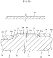
- the plating film 64 is formed by, for example, electroplating. Specifically, for example, as illustrated in FIG. 10 , an electrode 54 is disposed radially outside the substrate 62 in a plating solution. Masking members 56 and 58 are used for partially masking outer peripheral surfaces (masking surfaces) 68a and 28a of the support portions 68 and 28 and the outer peripheral surfaces 70a and 74a of the tilt portions 70 and 74. In the example of FIG. 10 , the masking members 56 and 58 are disposed to expose large parts of the outer peripheral surfaces 70a and 74a and the outer peripheral surface 72a.
- a potential difference is generated between the electrode 54 and the substrate 62. Accordingly, a plating film 64 is formed on the outer peripheral surfaces 70a, 72a, and 74a by metal ions in the plating solution.
- the plating portion 72 has a diameter larger than the diameters of the support portions (second base portion) 68 and 28, and the diameters of the tilt portions 70 and 74 gradually increase from the support portions 68 and 28 toward the plating portion 72.
- an electric resistance of the plating solution between the electrode 54 and the substrate 62 decreases as the distance between the electrode 54 and the substrate 62 decreases.
- the plating film 64 grows with higher priority in a portion of the outer peripheral surface of the substrate 62 close to the electrode 54.
- the plating portion 72 has a diameter larger than the diameter of each of the tilt portions 70 and 74.
- the distance between the electrode 54 and the outer peripheral surface (outer peripheral surface of the first base portion) 72a of the plating portion 72 is smaller than the distance between the electrode 54 and the outer peripheral surfaces (slopes) 70a and 74a of the tilt portions 70 and 74.
- an electric resistance of the plating solution between the electrode 54 and the outer peripheral surface 72a is smaller than an electric resistance of the plating solution between the electrode 54 and the outer peripheral surfaces 70a and 74a. Consequently, the plating film 64 can grow with higher priority on the outer peripheral surface 72a than on the outer peripheral surfaces 70a and 74a.
- the growth of the plating film 64 on the outer peripheral surfaces 70a and 74a can be made slower than the growth of the plating film 64 on the outer peripheral surface 72a.
- the thicknesses of the plating film 64 on the outer peripheral surfaces 70a and 74a can be easily made smaller than the thickness of the plating film 64 on the outer peripheral surface 72a. That is, without masking the substrate 62 with high accuracy in order to control the thicknesses of the end portions 64a and 64b of the plating film 64, the thicknesses of the end portions 64a and 64b can be easily made smaller than the thickness of the plating film 64 on the outer peripheral surface 72a.
- the diameters of the tilt portions 70 and 74 gradually increase from the support portions 68 and 28 toward the plating portion 72.
- the distance between the electrode 54 and the outer peripheral surfaces 70a and 74a in the radial direction of the substrate 62 gradually increases toward the support portions 68 and 28 in the axial direction of the substrate 62. That is, an electric resistance of the plating solution between the electrode 54 and the outer peripheral surfaces 70a and 74a gradually increases toward the support portions 68 and 28 in the axial direction of the substrate 62. Accordingly, the growth of the plating film 64 on the outer peripheral surfaces 70a and 74a becomes slower toward the support portions 68 and 28. In this manner, the thickness of the plating film 64 formed on the outer peripheral surfaces 70a and 74a can be made smaller toward the support portions 68 and 28. This further ensures reduction of the thicknesses of the end portions 64a and 64b of the plating film 64.
- a connection portion between the outer peripheral surface (slope) 70a of the tilt portion 70 and the outer peripheral surface (outer peripheral surface of the first base portion) 72a of the plating portion 72 has a curved shape in the vertical cross-section of the substrate 62.
- a connection portion between the outer peripheral surface (slope) 74a of the tilt portion 74 and the outer peripheral surface (outer peripheral surface of the first base portion) 72a of the plating portion 72 has a curved shape in the vertical cross-section of the substrate 62.
- the thickness of the plating film 64 can increase at this sharp edge.
- an increase in the thickness of the plating film 64 in the connection portion can be prevented by forming the connection portion to have a curved shape in the vertical cross-section of the substrate 12. In this manner, it is possible to prevent unevenness of a magnetic flux passing through a region of the plating film 64 near the connection portion. As a result, variations in outputs of the torque sensor 60 can be sufficiently reduced.
- the embodiment described above is directed to the case where the outer peripheral surfaces (masking surfaces) of the support portions 20, 28, and 68 (second base portion) are surfaces parallel to the shaft centers of the substrates 12 and 62 in the vertical cross-sections of the substrates 12 and 62.
- the outer peripheral surfaces of the support portions may be tilted relative to the shaft centers of the substrates in the vertical cross-sections of the substrates.
- the tilt portions 22, 26, 70, and 74 are disposed between the support portions 20 and 68 and the plating portions 24 and 72 and between the support portion 28 and the plating portions 24 and 72 in the axial directions of the substrates 12 and 62, respectively.
- the tilt portion may be provided only one of between the support portion 20 and the plating portion 24 or between the support portion 28 and the plating portion 24.
- each of the connection portions between the outer peripheral surfaces 22a and 70a and the outer peripheral surfaces 20a and 68a, the connection portions between the outer peripheral surfaces 22a and 70a and the outer peripheral surfaces 24a and 72a, the connection portions between the outer peripheral surfaces 26a and 74a and the outer peripheral surface 28a, and the connection portions between the outer peripheral surfaces 26a and 74a and the outer peripheral surfaces 24a and 72a has a curved shape in the vertical cross-section of the substrate 62.
- some or all of these connection portions may not have curved shapes but may have shapes other than curved shapes, such as linear shapes, in the vertical cross-sections of the substrates 12 and 62.
- the configurations of the bobbins 40 and 76 and the cases 46 and 82 of the torque sensors 10 and 60 described in the above embodiments are examples. Accordingly, the bobbins 40 and 76 and the cases 46 and 82 may have any configuration as long as magnetic fluxes passing through the magnetostrictive portions 36 and 38 can be generated by the detection coils 42a, 42b, 78a, and 78b.
- the connection configuration between the magnetostrictive unit 10a and the detection unit 10b is not limited to the configuration of the embodiment described above, and may be any configuration as long as the magnetostrictive unit 10a and the detection unit 10b can be connected to each other.
- the embodiment described above is directed to the case of applying the present teaching to torque sensors, but the present teaching is applicable to various magnetostrictive sensors.
- the present teaching may be applied to a magnetostrictive displacement sensor and may be applied to a magnetostrictive load sensor.
- the present teaching can be used for various magnetostrictive sensors for detecting changes in the magnetic permeability of a plating film.
Landscapes
- Physics & Mathematics (AREA)
- General Physics & Mathematics (AREA)
- Electromagnetism (AREA)
- Power Steering Mechanism (AREA)
Description
- The present teaching relates to a magnetostrictive sensor.
- A magnetostrictive sensor has been conventionally used for detecting a torque acting on a component of equipment or detecting a load acting on the component. A known configuration example of the magnetostrictive sensor includes: a columnar substrate having an outer peripheral surface on which a magnetostrictive portion is provided; and a detection coil that generates a magnetic flux passing through the magnetostrictive portion. In the case of using the magnetostrictive sensor having such a configuration as a torque sensor, when a force in a rotation direction is applied to the substrate, a tensile stress or a compressive stress occurs in the magnetostrictive portion. Accordingly, the magnetic permeability of the magnetostrictive portion changes. The torque sensor detects a change in the magnetic permeability of the magnetostrictive portion using the detection coil to thereby detect a force acting on the substrate.
- For example, an amorphous thin strap or a plating film can be used as the magnetostrictive portions. In the case of using an amorphous thin strap as the magnetostrictive portion, the sensitivity of the magnetostrictive sensor can be increased. In the case of using the amorphous thin strap as the magnetostrictive portion, the amorphous thin strap needs to be bonded to the outer peripheral surface of the substrate with an adhesive. To accurately bond the amorphous thin strap to the outer peripheral surface of the substrate, the adhesive needs to be uniformly applied onto the outer peripheral surface of the substrate. It is, however, difficult to uniformly apply the adhesive onto the outer peripheral surface of the substrate. In addition, if an inappropriate amount of the adhesive is used, for example, the adhesive is likely to extend off between the amorphous thin strap and the substrate in bonding the amorphous thin strap to the substrate. In this case, a process for removing the excess adhesive is needed. In addition, since the amorphous thin strap is thin, it is difficult to use the amorphous thin strap with an industrial robot. In view of these circumstances, in the case of using the amorphous thin strap as the magnetostrictive portion, it is difficult to enhance productivity.
- From the viewpoint of productivity, the use of a plating film as the magnetostrictive portion is conceivable. In the case of forming a plating film by electroplating, as disclosed in
Patent Document 1, for example, the substrate is immersed in a plating solution with a predetermined portion of the substrate masked with a masking member. Thereafter, a current is caused to flow in the plating solution so that a plating film is formed in an unmasked portion of the substrate. - Patent Document 1: Japanese Patent No.
4936969 - When the shape of plating films (e.g., distribution of film thickness) varies in mass-producing magnetostrictive sensors, outputs of the magnetostrictive sensors also vary. To reduce the occurrence of variations in outputs of the magnetostrictive sensors, plating films need to be formed with high reproducibility in order to prevent variations in the shape of the plating films. In this case, the masking needs to be controlled with high accuracy.
- In the case of mass-producing magnetostrictive sensors, however, it is difficult to mask substrates with high accuracy for various reasons, such as a dimensional error in substrates, a dimensional error in the masking members, and degradation of the masking members with time. Thus, it is difficult to suppress occurrence of variations in outputs of magnetostrictive sensors. It is also difficult to sufficiently enhance productivity of magnetostrictive sensors.
- It is therefore an object of the present teaching to provide a magnetostrictive sensor capable of obtaining both enhanced productivity and suppressed variations in outputs.
- The inventors of the present teaching studied the formation of a plating film by electroplating and found that, in some cases, the thickness of the plating film increases in an end portion thereof (a portion to come into contact with a masking member during the formation). It was found that in such cases, a magnetic flux generated by, for example, a detection coil and passing through the end portion of the plating film become nonuniform, resulting in the occurrence of variations in outputs of magnetostrictive sensors.
- It was also found that, in some cases, a variation also occurs in thickness distribution of the plating film in the circumferential direction of the substrate. In this case, the amount of a magnetic flux passing through the plating film varies depending on a rotation angle of the substrate relative to the detection coil, for example. Accordingly, even in a state where a force in the rotation direction does not act on the substrate (i.e., under no load), the value of a current flowing in the detection coil varies depending on the rotation angle of the substrate. Consequently, an output of a magnetostrictive sensor under no load varies depending on the rotation angle of the substrate, and thus, accuracy in detection by the magnetostrictive sensor decreases.
- In view of this, the inventors intensively studied the thickness of the plating film to find that the thickness of the end portion of the plating film increases and/or thickness distribution varies in the end portion of the plating film in a case where the masking is insufficiently controlled in forming the plating film.
- Further study by the inventors found that a reduction of the thickness of the end portion of the plating film can stabilize an output of the magnetostrictive sensor. Specifically, it was found that when the thickness of the end portion of the plating film is reduced, unevenness of a magnetic flux passing through the end portion can be reduced. In addition, it was found that even when the shape of the end portion of the plating film varies, variations in the amount of the magnetic flux passing through the end portion depending on the rotation angle of the substrate can be reduced. It was also found to be possible to reduce variations in the amount of the magnetic flux passing through the plating film depending on the rotation angle of the substrate accordingly.
- The inventors further found that the thickness of the end portion of the plating film can be reduced by causing a portion of the outer peripheral surface of the substrate where the end portion of the plating film is located to tilt relative to the shaft center of the substrate.
- Based on the foregoing findings, the inventors arrived at a configuration of a magnetostrictive sensor described below.
- A magnetostrictive sensor according to an embodiment of the present teaching includes: a columnar or tubular substrate; and a plating film disposed on an outer peripheral surface of the substrate, wherein the substrate includes a first base portion, a second base portion having a diameter larger than a diameter of the first base portion, and a tilt portion disposed between the first base portion and the second base portion in an axial direction of the substrate and connecting the first base portion and the second base portion, the first base portion has an outer peripheral surface parallel to a shaft center of the substrate in a cross-section including the shaft center and extending in the axial direction of the substrate, the tilt portion has an outer peripheral surface that is a slope tilted relative to the shaft center in the cross-section, the plating film is formed on the outer peripheral surface of the first base portion and on the slope in such a manner that one end of the plating film in the axial direction is located on the slope, and the plating film has a thickness on the slope smaller than a thickness of the plating film on the outer peripheral surface of the first base portion.
- A magnetostrictive sensor according to an embodiment of the present teaching can obtain both enhancement of productivity and reduction of variations in outputs.
-
- [
FIG. 1] FIG. 1 is a front view illustrating a schematic configuration of a torque sensor according to an embodiment of the present teaching. - [
FIG. 2] FIG. 2 is a vertical cross-sectional view illustrating the schematic configuration of the torque sensor illustrated inFIG. 1 in cross-section. - [
FIG. 3] FIG. 3 is a front view illustrating a magnetostrictive unit. - [
FIG. 4] FIG. 4 is a vertical cross-sectional view illustrating the magnetostrictive unit illustrated inFIG. 3 in cross-section. - [
FIG. 5] FIG. 5 shows enlarged views illustrating portions surrounded by broken lines inFIG. 4 in an enlarged manner. - [
FIG. 6] FIG. 6 is a view for describing an example of a method for forming a plating film. - [
FIG. 7] FIG. 7 is a vertical cross-sectional view illustrating a schematic configuration of a torque sensor according to another embodiment in cross-section. - [
FIG. 8] FIG. 8 is a vertical cross-sectional view illustrating another example of the magnetostrictive unit in cross-section. - [
FIG. 9] FIG. 9 shows enlarged views illustrating portions surrounded by broken lines inFIG. 8 in an enlarged manner. - [
FIG. 10] FIG. 10 is a view for describing another example of a method for forming a plating film. - A magnetostrictive sensor according to an embodiment of the present teaching will now be described. A magnetostrictive torque sensor will be hereinafter described as a magnetostrictive sensor according to an embodiment of the present teaching.
-
FIG. 1 is a front view illustrating a schematic configuration of atorque sensor 10 according to an embodiment of the present teaching.FIG. 2 is a vertical cross-sectional view illustrating the schematic configuration of thetorque sensor 10 in cross-section. - With reference to
FIGS. 1 and2 , thetorque sensor 10 includes amagnetostrictive unit 10a and adetection unit 10b. Each of themagnetostrictive unit 10a and thedetection unit 10b has a substantially tubular shape. Themagnetostrictive unit 10a is rotatably inserted in thedetection unit 10b, which will be described in detail later. In thetorque sensor 10, a torque acts on asubstrate 12 described later of themagnetostrictive unit 10a so that the magnetic permeability of a plating film 14 (seeFIG. 3 ) described later of themagnetostrictive unit 10a thereby changes. The change in the magnetic permeability of theplating film 14 is detected by a pair ofdetection coils detection unit 10b. In this manner, the torque acting on thesubstrate 12 is detected. Although not specifically described, thetorque sensor 10 can be used, for example, as a torque sensor for detecting a pedaling force in a driving device of an electric motor-assisted bicycle. - First, a configuration of the
magnetostrictive unit 10a will be described.FIG. 3 is a front view illustrating themagnetostrictive unit 10a.FIG. 4 is a vertical cross-sectional view illustrating themagnetostrictive unit 10a in cross-section.FIG. 5 shows enlarged views illustrating portions A and B surrounded by broken lines inFIG. 4 in an enlarged manner. - With reference to
FIGS. 3 and4 , themagnetostrictive unit 10a includes thetubular substrate 12, theplating film 14 disposed on the outer peripheral surface of thesubstrate 12, and anannular bearing member 16 fitted in an end portion of thesubstrate 12.FIG. 2 does not show theplating film 14 to simplify the illustration. - With reference to
FIGS. 3 and4 , thesubstrate 12 includes aflange portion 18, asupport portion 20, atilt portion 22, a plating portion 24 (first base portion), atilt portion 26, asupport portion 28, a holdingportion 30, and aflange portion 32, from oneend 12a to theother end 12b of thesubstrate 12 in an axial direction. - Although not specifically shown, a spline groove is formed on the outer peripheral surface of the
flange portion 18 to extend in the axial direction of thesubstrate 12. With reference toFIGS. 1 and2 , theflange portion 18 projects from thedetection unit 10b in the axial direction of thedetection unit 10b in a state where themagnetostrictive unit 10a is inserted in thedetection unit 10b. - With reference to
FIG. 4 , an outerperipheral surface 20a of thesupport portion 20 is a surface parallel to a shaft center of the substrate 12 (see a chain line inFIG. 4 ) in a cross-section of thesubstrate 12 including the shaft center and extending in the axial direction of the substrate 12 (hereinafter referred to as a vertical cross-section of the substrate 12). Similarly, each of an outerperipheral surface 24a of the platingportion 24 and an outerperipheral surface 28a of thesupport portion 28 is a surface parallel to the shaft center of thesubstrate 12 in the vertical cross-section of thesubstrate 12. The platingportion 24 has a diameter smaller than the diameter of thesupport portion 20. The platingportion 24 has a diameter smaller than the diameter of thesupport portion 28. In this embodiment, thesupport portions peripheral surface 24a corresponds to the outer peripheral surface of the first base portion. In this embodiment, each of thesupport portions - With reference to
FIGS. 4 and5 , thetilt portion 22 is disposed between thesupport portion 20 and theplating portion 24 in the axial direction of thesubstrate 12, and connects thesupport portion 20 and theplating portion 24 to each other. An outerperipheral surface 22a of thetilt portion 22 is a slope tilted relative to the shaft center of thesubstrate 12 in the vertical cross-section of thesubstrate 12. In this embodiment, the diameter of thetilt portion 22 gradually decreases from thesupport portion 20 toward the platingportion 24. Accordingly, in the vertical cross-section of thesubstrate 12, the outerperipheral surface 22a tilts relative to the shaft center of thesubstrate 12 radially inward in thesubstrate 12 from the outerperipheral surface 20a toward the outerperipheral surface 24a. - The
tilt portion 26 is disposed between thesupport portion 28 and theplating portion 24 in the axial direction of thesubstrate 12, and connects thesupport portion 28 and theplating portion 24 to each other. An outerperipheral surface 26a of thetilt portion 26 is a slope tilted relative to the shaft center of thesubstrate 12 in the vertical cross-section of thesubstrate 12. In this embodiment, the diameter of thetilt portion 26 gradually decreases from thesupport portion 28 toward the platingportion 24. Accordingly, in the vertical cross-section, the outerperipheral surface 26a tilts relative to the shaft center of thesubstrate 12 radially inward in thesubstrate 12 from the outerperipheral surface 28a toward the outerperipheral surface 24a. - With reference to
FIG. 5 , a connection portion between the outerperipheral surface 22a and the outerperipheral surface 20a and a connection portion between the outerperipheral surface 22a and the outerperipheral surface 24a have curved shapes in the vertical cross-section of thesubstrate 12. Similarly, a connection portion between the outerperipheral surface 26a and the outerperipheral surface 28a and a connection portion between the outerperipheral surface 26a and the outerperipheral surface 24a have curved shapes in the vertical cross-section of thesubstrate 12. - With reference to
FIGS. 3 and4 , the holdingportion 30 has a diameter smaller than each of the diameter of thesupport portion 28 and the diameter of theflange portion 32. In this manner, agroove 30a is formed between thesupport portion 28 and theflange portion 32. - With reference to
FIGS. 2 and4 , aspline groove 34 is formed on the inner peripheral surface of thesubstrate 12 to extend in the axial direction of thesubstrate 12. InFIGS. 2 and4 , thespline groove 34 is simplified. Thespline groove 34 is formed closer to theother end 12b than the center of thesubstrate 12 in the axial direction of thesubstrate 12. In this embodiment, afront end 34a of the spline groove 34 (an end toward theother end 12b in the axial direction of the substrate 12) is located closer to the inside of thesubstrate 12 than theother end 12b in the axial direction of thesubstrate 12. That is, thespline groove 34 is formed closer to the inside of thesubstrate 12 than theother end 12b in the axial direction of thesubstrate 12. - The thickness of the
substrate 12 is larger in a center portion of thesubstrate 12 than in end portions of thesubstrate 12 in the axial direction thereof. With reference toFIG. 2 , in this embodiment, the thickness of thesubstrate 12 in portions facing a pair ofdetection coils substrate 12. - The
substrate 12 is made of, for example, a metal material (e.g., chromium molybdenum steel). In this embodiment, thesubstrate 12 is produced by, for example, forging and machining. Specifically, for example, first, a metal material cut out from a metal wire material to have a predetermined length is forged, and thereby, a hollow member is obtained. Thespline groove 34 and the spline groove in theflange portion 18 described above are shaped by the forging. Next, the forged member is subjected to thermal refining (e.g., hardening and tempering), and then, the outer peripheral surface of the member is cut by machining (e.g., turning). In this manner, the outerperipheral surfaces substrate 12 is obtained. - With reference to
FIG. 3 , theplating film 14 is made of a magnetostrictive material (e.g., a Fe-Ni alloy) and functions as a magnetostrictive portion. Theplating film 14 is formed by, for example, electroplating. With reference toFIGS. 4 and5 , theplating film 14 is formed on the outerperipheral surface 24a of the platingportion 24 and the outerperipheral surfaces tilt portions end 14a of theplating film 14 is located on the outerperipheral surface 22a, and theother end 14b of theplating film 14 is located on the outerperipheral surface 26a. The thickness of theplating film 14 on the outerperipheral surface 22a and the thickness of theplating film 14 on the outerperipheral surface 26a are smaller than the thickness of theplating film 14 on the outerperipheral surface 24a. The thickness of theplating film 14 on the outerperipheral surface 22a, the thickness of theplating film 14 on the outerperipheral surface 26a, and the thickness of theplating film 14 on the outerperipheral surface 24a respectively refer to an average thickness of theplating film 14 on the outerperipheral surface 22a, an average thickness of theplating film 14 on the outerperipheral surface 26a, and an average thickness of theplating film 14 on the outerperipheral surface 24a. - With reference to
FIG. 3 , in this embodiment, theplating film 14 includes amagnetostrictive portion 36 and amagnetostrictive portion 38. Themagnetostrictive portion 36 includes a plurality ofslits 36a. Themagnetostrictive portion 38 includes a plurality ofslits 38a. The plurality ofslits 36a are arranged at regular intervals in the circumferential direction of thesubstrate 12. Similarly, the plurality ofslits 38a are arranged at regular intervals in the circumferential direction of thesubstrate 12. - When viewed from outside in the radial direction of the
substrate 12, theslits 36a are tilted 45° relative to the shaft center of thesubstrate 12. When viewed from outside in the radial direction of thesubstrate 12, theslits 38a are tilted 45° in a direction different from theslits 36a relative to the shaft center of thesubstrate 12. That is, in this embodiment, the plurality ofslits plating film 14 in such a manner that theslits 36a and theslits 38a intersect with each other perpendicularly. With this configuration, when a torque acts on thesubstrate 12, a compressive stress occurs in one of themagnetostrictive portions FIGS. 4 and5 do not show the plurality ofslits - With reference to
FIGS. 2 and4 , the bearingmember 16 is made of, for example, a metal material. The bearingmember 16 is press fitted in thesubstrate 12 from the oneend 12a of thesubstrate 12. - With reference to
FIGS. 1 and2 , thedetection unit 10b includes abobbin 40, a pair ofdetection coils connector 44, acase 46, a pair ofprotective plates circlip 50. - The
bobbin 40 is made of, for example, a resin material. With reference toFIG. 2 , thebobbin 40 has a substantially tubular shape. Specifically, thebobbin 40 includes atubular portion 40a and a plurality of (four in this embodiment)flange portions 40b through 40e projecting from the outer peripheral surface of thetubular portion 40a outward in the radial direction of thetubular portion 40a. Theflange portions 40b through 40e are arranged at intervals from one another in the axial direction of thetubular portion 40a. - The
detection coil 42a is wound around thetubular portion 40a between theflange portion 40b and theflange portion 40c. Thedetection coil 42b is wound around thetubular portion 40a between theflange portion 40d and theflange portion 40e. In this embodiment, for example, the detection coils 42a and 42b include welded layers. In the detection coils 42a and 42b, adjacent coil wires are fixed to each other by self-welding. The detection coils 42a and 42b may not include welded layers. In this case, adjacent coil wires may be fixed to each other with another technique such as impregnation. - Although not specifically described, the
flange portion 40b is provided with a plurality of terminals electrically connected to the detection coils 42a and 42b. To protect these terminals, aconnector 44 is attached to theflange portion 40b. These plurality of terminals are electrically connected to terminals of an unillustrated control board. The control board is provided with an arithmetic circuit. The arithmetic circuit calculates a torque acting on thesubstrate 12 based on changes in the impedances of the detection coils 42a and 42b, for example. - With reference to
FIGS. 1 and2 , thecase 46 is made of, for example, a metal material such as low-carbon steel. Thecase 46 has a tubular shape. With reference toFIG. 2 , thebobbin 40 is inserted in thecase 46. Thecase 46 covers radially outsides of the detection coils 42a and 42b. - With reference to
FIG. 1 , one end portion of thecase 46 has a plurality of substantially U-shaped throughholes 46a. The formation of the throughholes 46a forms substantiallyrectangular swaging portions 46b. In this embodiment, the plurality ofswaging portions 46b are formed at regular intervals in the circumferential direction of thecase 46. Thecase 46 is fixed to thebobbin 40 by swaging using the plurality ofswaging portions 46b. - With reference to
FIGS. 1 and2 , each of theprotective plates protective plates protective plate 48a is disposed between one end surface of thebobbin 40 and theflange portion 18 of thesubstrate 12. Theprotective plate 48b is disposed between the other end surface of thebobbin 40 and thecirclip 50. In this embodiment, theprotective plate 48a is provided to prevent abrasion of the one end surface of thebobbin 40. Theprotective plate 48a is provided to prevent abrasion of the other end surface of thebobbin 40. Thecirclip 50 has a substantially C-shape, and is fitted in thegroove 30a of thesubstrate 12. In this embodiment, thecirclip 50 is made of a metal material. Thecirclip 50 is disposed to prevent thebobbin 40 and theprotective plates substrate 12 relative to thesubstrate 12. - With reference to
FIG. 2 , in attaching thedetection unit 10b to themagnetostrictive unit 10a, theprotective plate 48a is fitted in thesubstrate 12 from theother end 12b of thesubstrate 12, for example. Next, thebobbin 40, the detection coils 42a and 42b, theconnector 44, and thecase 46 that are integrally formed are fitted in thesubstrate 12 from theother end 12b of thesubstrate 12. Thereafter, theprotective plate 48b is fitted in thesubstrate 12 from theother end 12b of thesubstrate 12. Lastly, thecirclip 50 is fitted in thegroove 30a. In this manner, attachment of thedetection unit 10b to themagnetostrictive unit 10a is completed. - In this embodiment, in the
substrate 12, the outerperipheral surface 20a of thesupport portion 20 and the outerperipheral surface 28a of thesupport portion 28 are rotatably supported on the inner peripheral surface of thebobbin 40. Thebobbin 40 covers theplating film 14 from radially outside of thesubstrate 12 not to contact the plating film 14 (seeFIG. 3 ). The detection coils 42a and 42b are disposed at positions facing theplating film 14 in the radial direction of thesubstrate 12. More specifically, in the radial direction of thesubstrate 12, thedetection coil 42a is disposed at a position facing themagnetostrictive portion 36, and thedetection coil 42b is disposed at a position facing themagnetostrictive portion 38. In this embodiment, thesubstrate 12 is directly supported on the inner peripheral surface of thebobbin 40 as described above. Alternatively, thesubstrate 12 may be indirectly supported on the inner peripheral surface of thebobbin 40 with a ring-shaped bearing member or another member interposed therebetween. - The
torque sensor 10 according to this embodiment can be used, for example, as a torque sensor for detecting a pedaling force in a driving device of an electric motor-assisted bicycle. In this case, with reference toFIG. 2 , acrank shaft 52 of the electric motor-assisted bicycle is inserted in thesubstrate 12. Specifically, thecrank shaft 52 is inserted in thesubstrate 12 in such a manner that a spline groove (not shown) formed on the outer peripheral surface of thecrank shaft 52 and thespline groove 34 on the inner peripheral surface of thesubstrate 12 mesh with each other. In this manner, a torque can be transferred from thecrank shaft 52 to thesubstrate 12. - The
flange portion 18 of thesubstrate 12 is, for example, connected to a chain sprocket (not shown) of the electric motor-assisted bicycle through a one-way clutch. Thedetection unit 10b (more specifically thebobbin 40, for example) is fixed to a housing of the driving device (not shown) by using an unillustrated fixing member. - In the configuration described above, when a torque is transferred from the
crank shaft 52 to thesubstrate 12, a compressive stress occurs in themagnetostrictive portion 36 and a tensile stress occurs in themagnetostrictive portion 38, for example. In this manner, the magnetic permeability of themagnetostrictive portion 36 decreases, and the magnetic permeability of themagnetostrictive portion 38 increases. Consequently, an impedance of thedetection coil 42a decreases, and an impedance of thedetection coil 42b increases. Based on changes in the impedances of the detection coils 42a and 42b, thetorque sensor 10 can detect a torque acting on thesubstrate 12. - A method for forming the
plating film 14 will be briefly described below.FIG. 6 is a view for describing an example of a method for forming theplating film 14. The method for forming theplating film 14 is not limited to the following examples, and theplating film 14 may be formed by using various known methods. - With reference to
FIG. 6 , in forming theplating film 14, anelectrode 54 is disposed radially outside thesubstrate 12 in a plating solution, for example. Maskingmembers support portions FIG. 6 , in the axial direction of thesubstrate 12, a front end portion of the maskingmember 56 projects toward the outerperipheral surface 22a relative to a connection portion between the outerperipheral surface 20a and the outerperipheral surface 22a. In the axial direction of thesubstrate 12, a front end portion of the maskingmember 58 projects toward the outerperipheral surface 26a relative to a connection portion between the outerperipheral surface 28a and the outerperipheral surface 26a. Although not shown, in forming theplating film 14, theflange portion 18, the holdingportion 30, and theflange portion 32 are also masked with the maskingmembers - After the
electrode 54 and the maskingmembers electrode 54 and thesubstrate 12. Accordingly, aplating film 14 is formed on the outer peripheral surface of thesubstrate 12 by metal ions in the plating solution. In the example ofFIG. 6 , since the outerperipheral surfaces members plating film 14 is formed on the outerperipheral surfaces - In the
torque sensor 10, thetilt portion 22 is disposed between the plating portion 24 (first base portion) and the support portion (second base portion) 20, and is connected to theplating portion 24 and thesupport portion 20. Thetilt portion 26 is disposed between the plating portion 24 (first base portion) and the support portion (second base portion) 28, and is connected to theplating portion 24 and thesupport portion 28. The platingportion 24 has a diameter smaller than the diameter of each of thesupport portions tilt portions support portions portion 24. With this configuration, in the case of forming theplating film 14 as illustrated inFIG. 6 , for example, a space that gradually narrows toward thesupport portion 20 is formed between the front end portion of the maskingmember 56 and the outerperipheral surface 22a. Similarly, a space that gradually narrows toward thesupport portion 28 is formed between the front end portion of the maskingmember 58 and the outerperipheral surface 26a. In this case, in forming theplating film 14, the amount of metal ions supplied to the outerperipheral surfaces support portions plating film 14 formed on the outerperipheral surfaces support portions substrate 12 with high accuracy in order to control the thicknesses of theend portions plating film 14, the thicknesses of theend portions plating film 14 on the outerperipheral surface 24a of the platingportion 24. The thicknesses of theend portions plating film 14 refer to averages of the thicknesses of theplating film 14 in theend portions plating film 14 on the outerperipheral surface 24a of the platingportion 24 refers to an average thickness of theplating film 14 on the outerperipheral surface 24a of the platingportion 24. - Since the thicknesses of the
end portions plating film 14 are small as described above, in generating a magnetic flux by the detection coils 42a and 42b, for example, it is possible to reduce unevenness of magnetic fluxes passing through theend portions end portions plating film 14 are small, even when the shape of theend portions end portions plating film 14 depending on the rotation angle of thesubstrate 12. In this manner, it is possible to reduce variations in the amount of the magnetic fluxes passing through theplating film 14 depending on the rotation angle of thesubstrate 12. As a result, an output of thetorque sensor 10 can be stabilized. - Accordingly, in this embodiment, without masking the
substrate 12 with high accuracy in forming theplating film 14, the occurrence of variations in outputs of thetorque sensor 10 can be suppressed. That is, both enhancement of productivity and reduction of variations in outputs of thetorque sensor 10 can be achieved. - In the
torque sensor 10, a connection portion between the outerperipheral surface 22a of thetilt portion 22 and the outerperipheral surface 20a of thesupport portion 20 has a curved shape in the vertical cross-section of thesubstrate 12. Similarly, a connection portion between the outerperipheral surface 26a of thetilt portion 26 and the outerperipheral surface 28a of thesupport portion 28 has a curved shape in the vertical cross-section of thesubstrate 12. Here, in a cutting process of thesubstrate 12, in some cases, minute burrs can occur in the connection portions. In such cases, even when the connection portions are covered with the maskingmembers plating film 14, the burrs might be plated. In such a case that the burrs are plated, the burrs enlarged by plating might damage components (e.g., the bobbin 40) of thetorque sensor 10. However, since the connection portions have curved shapes in the vertical cross-section of thesubstrate 12, the occurrence of burrs in the connection portions in cutting thesubstrate 12 can be prevented. In this manner, damage of components of thetorque sensor 10 can be prevented. - In the
torque sensor 10, thebobbin 40 covers theplating film 14 from radially outside of thesubstrate 12. Accordingly, theplating film 14 can be protected by thebobbin 40. In thesubstrate 12, the outerperipheral surfaces bobbin 40. In this manner, contact between the platingfilm 14 and thebobbin 40 can be prevented. Consequently, damage of theplating film 14 can be prevented. - In the
substrate 12 of themagnetostrictive unit 10a described above, the diameter of the plating portion 24 (first base portion) is smaller than the diameters of the support portions (second base portion) 20 and 28. The shape of the substrate, however, is not limited to the example described above. For example, the diameter of the plating portion (first base portion) may be larger than the diameter of the support portion (second base portion). Atorque sensor 60 having such a configuration will be briefly described below. -
FIG. 7 is a vertical cross-sectional view illustrating a schematic configuration of thetorque sensor 60 according to another embodiment of the present teaching in cross-section. Thetorque sensor 60 includes amagnetostrictive unit 60a and adetection unit 60b. Thetorque sensor 60 will now be briefly described mainly for aspects different from thetorque sensor 10 described above.FIG. 7 does not show aplating film 64 described later in order to simplify the illustration. -
FIG. 8 is a vertical cross-sectional view illustrating themagnetostrictive unit 60a in cross-section.FIG. 9 shows enlarged views illustrating portions C and D surrounded by broken lines inFIG. 8 in an enlarged manner. Themagnetostrictive unit 60a is different from themagnetostrictive unit 10a described above in the following aspects. With reference toFIG. 8 , themagnetostrictive unit 60a includes asubstrate 62 and aplating film 64, instead of thesubstrate 12 and theplating film 14 of themagnetostrictive unit 10a. - The
substrate 62 is different from thesubstrate 12 described above in the following aspects. With reference toFIG. 8 , thesubstrate 62 includes a holdingportion 66, asupport portion 68, atilt portion 70, a plating portion 72 (first base portion), and atilt portion 74, instead of thesupport portion 20, thetilt portion 22, the platingportion 24, and thetilt portion 26 of thesubstrate 12. - With reference to
FIG. 8 , an outerperipheral surface 66a of the holdingportion 66 is a surface parallel to a shaft center of the substrate 62 (see a chain line inFIG. 8 ) in a cross-section of thesubstrate 62 including the shaft center and extending in the axial direction of the substrate 62 (hereinafter referred to as a vertical cross-section of the substrate 62). Similarly, an outerperipheral surface 68a of thesupport portion 68 and an outerperipheral surface 72a of the platingportion 72 are surfaces parallel to the shaft center of thesubstrate 62 in the vertical cross-section of thesubstrate 62. The holdingportion 66 has a diameter smaller than each of the diameter of theflange portion 18 and the diameter of thesupport portion 68. With this configuration, agroove 66b is formed between theflange portion 18 and thesupport portion 68. The platingportion 72 has a diameter larger than the diameter of each of thesupport portions support portions peripheral surface 72a corresponds to the outer peripheral surface of the first base portion. In this embodiment, thesupport portion 68 has a diameter larger than each of the diameter of theflange portion 18 and the diameter of thesupport portion 28. - With reference to
FIGS. 8 and9 , thetilt portion 70 is disposed between thesupport portion 68 and theplating portion 72 in the axial direction of thesubstrate 62, and connects thesupport portion 68 and theplating portion 72 to each other. With reference toFIG. 9 , an outerperipheral surface 70a of thetilt portion 70 is a slope tilted relative to the shaft center of thesubstrate 62 in the vertical cross-section of thesubstrate 62. In this embodiment, the diameter of thetilt portion 70 gradually increases from thesupport portion 68 toward the platingportion 72. Accordingly, in the vertical cross-section, the outerperipheral surface 70a tilts relative to the shaft center of thesubstrate 62 radially outward of thesubstrate 62 from the outerperipheral surface 68a toward the outerperipheral surface 72a. - With reference to
FIGS. 8 and9 , thetilt portion 74 is disposed between thesupport portion 28 and theplating portion 72 in the axial direction of thesubstrate 62, and connects thesupport portion 28 and theplating portion 72 to each other. With reference toFIG. 9 , an outerperipheral surface 74a of thetilt portion 74 is a slope tilted relative to the shaft center of thesubstrate 62 in the vertical cross-section of thesubstrate 62. In this embodiment, the diameter of thetilt portion 74 gradually increases from thesupport portion 28 toward the platingportion 72. Accordingly, in the vertical cross-section, the outerperipheral surface 74a tilts relative to the shaft center of thesubstrate 62 radially outward of thesubstrate 62 from the outerperipheral surface 28a toward the outerperipheral surface 72a. - Each of a connection portion between the outer
peripheral surface 70a and the outerperipheral surface 68a and a connection portion between the outerperipheral surface 70a and the outerperipheral surface 72a has a curved shape in the vertical cross-section of thesubstrate 62. Similarly, each of a connection portion between the outerperipheral surface 74a and the outerperipheral surface 28a and a connection portion between the outerperipheral surface 74a and the outerperipheral surface 72a has a curved shape in the vertical cross-section of thesubstrate 62. - With reference to
FIGS. 8 and9 , theplating film 64 is formed on the outerperipheral surface 72a of the platingportion 72 and the outerperipheral surfaces tilt portions FIG. 9 , oneend portion 64a of theplating film 64 is located on the outerperipheral surface 70a. Theother end portion 64b of theplating film 64 is located on the outerperipheral surface 74a. The thickness of theplating film 64 on the outerperipheral surface 70a and the thickness of theplating film 64 on the outerperipheral surface 74a are smaller than the thickness of theplating film 64 on the outerperipheral surface 72a. Theplating film 64 also includes a plurality of slits similar to the plurality ofslits plating film 64 on the outerperipheral surface 70a, the thickness of theplating film 64 on the outerperipheral surface 74a, and the thickness of theplating film 64 on the outerperipheral surface 72a respectively refer to an average thickness of theplating film 64 on the outerperipheral surface 70a, an average thickness of theplating film 64 on the outerperipheral surface 74a, and an average thickness of theplating film 64 on the outerperipheral surface 72a. - With reference to
FIG. 7 , thedetection unit 60b includes abobbin 76,detection coils connector 80, acase 82,protective plates circlips members bobbin 76, the detection coils 78a and 78b, theconnector 80, thecase 82, theprotective plates circlips bobbin 40, the detection coils 42a and 42b, theconnector 44,case 46, theprotective plates circlip 50 of thedetection unit 10b, respectively, and thus, detailed description will be omitted. - Each of the bearing
members members member 88a is fitted in thesubstrate 62 from one end of thesubstrate 62. The bearingmember 88b is fitted in thesubstrate 62 from the other end of thesubstrate 62. In this embodiment, thesubstrate 62 is rotatably supported indirectly on thebobbin 76 with the bearingmembers substrate 62, the outerperipheral surface 68a of thesupport portion 68 and the outerperipheral surface 28a of thesupport portion 28 are rotatably supported on the inner peripheral surface of thebobbin 76 with the bearingmembers bobbin 76 covers theplating film 64 from radially outside of thesubstrate 64 not to contact the plating film 64 (seeFIG. 8 ). - The
protective plate 84a and thecirclip 86a are disposed between thebobbin 76 and aflange portion 18 of thesubstrate 62. In this embodiment, theprotective plate 84a and thecirclip 86a are fitted in thegroove 66b of thesubstrate 62 in such a manner that theprotective plate 84a contacts one end surface of thebobbin 76. Theprotective plate 84b is disposed to contact the other end surface of thebobbin 76. Thecirclip 86b is fitted in thegroove 30a of thesubstrate 62 in such a manner that thecirclip 86b contacts one surface of theprotective plate 84b (a surface opposite to a surface thebobbin 76 contacts). In this embodiment, thecirclips bobbin 76 and thebearing members substrate 62. - A method for forming the
plating film 64 will be briefly described. Theplating film 64 is formed by, for example, electroplating. Specifically, for example, as illustrated inFIG. 10 , anelectrode 54 is disposed radially outside thesubstrate 62 in a plating solution. Maskingmembers support portions peripheral surfaces tilt portions FIG. 10 , the maskingmembers peripheral surfaces peripheral surface 72a. After theelectrode 54 and the maskingmembers electrode 54 and thesubstrate 62. Accordingly, aplating film 64 is formed on the outerperipheral surfaces - As described above, in this embodiment, the plating
portion 72 has a diameter larger than the diameters of the support portions (second base portion) 68 and 28, and the diameters of thetilt portions support portions portion 72. Here, with reference toFIG. 10 , in general, an electric resistance of the plating solution between theelectrode 54 and thesubstrate 62 decreases as the distance between theelectrode 54 and thesubstrate 62 decreases. Thus, theplating film 64 grows with higher priority in a portion of the outer peripheral surface of thesubstrate 62 close to theelectrode 54. In thesubstrate 62, the platingportion 72 has a diameter larger than the diameter of each of thetilt portions electrode 54 and the outer peripheral surface (outer peripheral surface of the first base portion) 72a of the platingportion 72 is smaller than the distance between theelectrode 54 and the outer peripheral surfaces (slopes) 70a and 74a of thetilt portions electrode 54 and the outerperipheral surface 72a is smaller than an electric resistance of the plating solution between theelectrode 54 and the outerperipheral surfaces plating film 64 can grow with higher priority on the outerperipheral surface 72a than on the outerperipheral surfaces plating film 64 on the outerperipheral surfaces plating film 64 on the outerperipheral surface 72a. In this manner, the thicknesses of theplating film 64 on the outerperipheral surfaces plating film 64 on the outerperipheral surface 72a. That is, without masking thesubstrate 62 with high accuracy in order to control the thicknesses of theend portions plating film 64, the thicknesses of theend portions plating film 64 on the outerperipheral surface 72a. - In addition, as described above, the diameters of the
tilt portions support portions portion 72. In this case, the distance between theelectrode 54 and the outerperipheral surfaces substrate 62 gradually increases toward thesupport portions substrate 62. That is, an electric resistance of the plating solution between theelectrode 54 and the outerperipheral surfaces support portions substrate 62. Accordingly, the growth of theplating film 64 on the outerperipheral surfaces support portions plating film 64 formed on the outerperipheral surfaces support portions end portions plating film 64. - In the foregoing manner, in this embodiment, without masking the
substrate 62 with high accuracy in forming theplating film 64, the occurrence of variations in outputs of thetorque sensor 60 can be reduced similarly to the embodiment described above. That is, both enhancement of productivity and reduction of variations in outputs of thetorque sensor 60 can be achieved. - In this embodiment, a connection portion between the outer peripheral surface (slope) 70a of the
tilt portion 70 and the outer peripheral surface (outer peripheral surface of the first base portion) 72a of the platingportion 72 has a curved shape in the vertical cross-section of thesubstrate 62. Similarly, a connection portion between the outer peripheral surface (slope) 74a of thetilt portion 74 and the outer peripheral surface (outer peripheral surface of the first base portion) 72a of the platingportion 72 has a curved shape in the vertical cross-section of thesubstrate 62. Here, in thesubstrate 62 in which the outer peripheral surface (outer peripheral surface of the first base portion) 72a projects from the outer peripheral surfaces (masking surfaces) 68a and 28a, if the connection portion has a sharp edge, in some cases, the thickness of theplating film 64 can increase at this sharp edge. However, in this embodiment, an increase in the thickness of theplating film 64 in the connection portion can be prevented by forming the connection portion to have a curved shape in the vertical cross-section of thesubstrate 12. In this manner, it is possible to prevent unevenness of a magnetic flux passing through a region of theplating film 64 near the connection portion. As a result, variations in outputs of thetorque sensor 60 can be sufficiently reduced. - Although the embodiment described above is directed to the case of using the
tubular substrates - The embodiment described above is directed to the case where the outer peripheral surfaces (masking surfaces) of the
support portions substrates substrates - In the embodiment described above, the
tilt portions support portions portions support portion 28 and the platingportions substrates support portion 20 and theplating portion 24 or between thesupport portion 28 and theplating portion 24. - In the embodiment described above, each of the connection portions between the outer
peripheral surfaces peripheral surfaces peripheral surfaces peripheral surfaces peripheral surfaces peripheral surface 28a, and the connection portions between the outerperipheral surfaces peripheral surfaces substrate 62. However, some or all of these connection portions may not have curved shapes but may have shapes other than curved shapes, such as linear shapes, in the vertical cross-sections of thesubstrates - The configurations of the
bobbins cases torque sensors bobbins cases magnetostrictive portions detection coils magnetostrictive unit 10a and thedetection unit 10b is not limited to the configuration of the embodiment described above, and may be any configuration as long as themagnetostrictive unit 10a and thedetection unit 10b can be connected to each other. - The embodiment described above is directed to the case of applying the present teaching to torque sensors, but the present teaching is applicable to various magnetostrictive sensors. For example, the present teaching may be applied to a magnetostrictive displacement sensor and may be applied to a magnetostrictive load sensor.
- The present teaching can be used for various magnetostrictive sensors for detecting changes in the magnetic permeability of a plating film.
Claims (7)
- A magnetostrictive sensor comprising:a columnar or tubular substrate; anda plating film disposed on an outer peripheral surface of the substrate, whereinthe substrate includes a first base portion, a second base portion having a diameter larger than a diameter of the first base portion, and a tilt portion disposed between the first base portion and the second base portion in an axial direction of the substrate and connecting the first base portion and the second base portion,the first base portion has an outer peripheral surface parallel to a shaft center of the substrate in a cross-section including the shaft center and extending in the axial direction of the substrate,the tilt portion has an outer peripheral surface being a slope tilted relative to the shaft center in the cross-section,the plating film is formed on the outer peripheral surface of the first base portion and on the slope in such a manner that one end of the plating film in the axial direction is located on the slope, andthe plating film has a thickness on the slope smaller than a thickness of the plating film on the outer peripheral surface of the first base portion.
- The magnetostrictive sensor of claim 1, wherein a diameter of the tilt portion gradually decreases from the second base portion toward the first base portion.
- The magnetostrictive sensor of claim 2, wherein a connection portion between the slope and an outer peripheral surface of the second base portion has a curved shape in the cross-section.
- The magnetostrictive sensor of claim 1, wherein a diameter of the tilt portion gradually increases from the second base portion toward the first base portion.
- The magnetostrictive sensor of claim 4, wherein a connection portion between the slope and the outer peripheral surface of the first base portion has a curved shape in the cross-section.
- The magnetostrictive sensor of any one of claims 1 to 5, wherein
the substrate comprises a pair of the tilt portions and a pair of the second base portions,
in the axial direction, one of the pair of tilt portions is connected to one end of the first base portion, whereas the other one of the pair of tilt portions is connected to the other end of the first base portion,
one of the pair of second base portions is connected to the one of the tilt portions, whereas the other one of the pair of second base portions is connected to the other one of the tilt portions,
one end of the plating film in the axial direction is formed on a slope of the one of the tilt portions, whereas the other end of the plating film in the axial direction is formed on a slope of the other one of the tilt portions, and
each of the one and the other ends of the plating film has a thickness smaller than a thickness of the plating film on the outer peripheral surface of the first base portion. - The magnetostrictive sensor of any one of claims 1 to 6, further comprising:a detection coil detects a change in a magnetic permeability of the plating film; anda tubular bobbin which holds the detection coil and in which the substrate is inserted, whereinthe bobbin covers the plating film from radially outside of the substrate, andthe second base portion of the substrate is rotatably supported directly or indirectly on an inner peripheral surface of the bobbin.
Applications Claiming Priority (2)
| Application Number | Priority Date | Filing Date | Title |
|---|---|---|---|
| JP2015196279 | 2015-10-01 | ||
| PCT/JP2016/079157 WO2017057750A1 (en) | 2015-10-01 | 2016-09-30 | Magnetostrictive sensor |
Publications (3)
| Publication Number | Publication Date |
|---|---|
| EP3343191A1 true EP3343191A1 (en) | 2018-07-04 |
| EP3343191A4 EP3343191A4 (en) | 2018-08-22 |
| EP3343191B1 EP3343191B1 (en) | 2021-08-25 |
Family
ID=58427758
Family Applications (1)
| Application Number | Title | Priority Date | Filing Date |
|---|---|---|---|
| EP16851919.7A Active EP3343191B1 (en) | 2015-10-01 | 2016-09-30 | Magnetostrictive sensor |
Country Status (4)
| Country | Link |
|---|---|
| US (1) | US10281346B2 (en) |
| EP (1) | EP3343191B1 (en) |
| JP (1) | JP6413028B2 (en) |
| WO (1) | WO2017057750A1 (en) |
Cited By (1)
| Publication number | Priority date | Publication date | Assignee | Title |
|---|---|---|---|---|
| WO2022100943A1 (en) * | 2020-11-13 | 2022-05-19 | Zf Friedrichshafen Ag | Method for producing a deformation body for measuring a force and/or a torque for a roll stabilization system for a vehicle, and deformation body |
Families Citing this family (1)
| Publication number | Priority date | Publication date | Assignee | Title |
|---|---|---|---|---|
| WO2016208688A1 (en) * | 2015-06-23 | 2016-12-29 | ヤマハ発動機株式会社 | Magnetostrictive sensor, magnetic structure and production method thereof, motor drive unit provided with magnetostrictive sensor, and motor assisted bicycle |
Family Cites Families (17)
| Publication number | Priority date | Publication date | Assignee | Title |
|---|---|---|---|---|
| JPH0387623A (en) * | 1989-08-30 | 1991-04-12 | Komatsu Ltd | Torque sensor shaft |
| JPH0424530A (en) * | 1990-05-19 | 1992-01-28 | Ono Sokki Co Ltd | magnetostrictive torque sensor |
| JP2702840B2 (en) * | 1992-02-03 | 1998-01-26 | 日産自動車株式会社 | Torque detector |
| US5280729A (en) * | 1991-04-30 | 1994-01-25 | Nissan Motor Co., Ltd. | Magnetostrictive torque detecting apparatus |
| EP0609463B1 (en) * | 1992-08-24 | 1999-11-17 | Kubota Corporation | Method for manufacturing magnetostriction type torque sensor shaft, and the shaft |
| JP2974553B2 (en) * | 1993-08-23 | 1999-11-10 | 日産自動車株式会社 | Magnetostriction measurement axis |
| JPH10176966A (en) * | 1996-12-18 | 1998-06-30 | Suzuki Motor Corp | Magnetostrictive detector for torque sensor |
| JPH11287718A (en) * | 1998-04-02 | 1999-10-19 | Toyota Autom Loom Works Ltd | Magnetostriction type torque sensor |
| JPH11344394A (en) * | 1998-05-29 | 1999-12-14 | Toyota Autom Loom Works Ltd | Torque sensor |
| US6301976B1 (en) * | 1999-03-18 | 2001-10-16 | Trw Inc. | Torque sensing apparatus having a magnetoelastic member secured to a shaft |
| SE517710C2 (en) * | 1999-12-14 | 2002-07-09 | Abb Ab | Magnetostrictive sensor for measuring torque and use of the sensor |
| US6341534B1 (en) * | 2000-03-03 | 2002-01-29 | Ford Motor Company | Integrated two-channel torque sensor |
| EP1477788B1 (en) | 2003-05-12 | 2006-04-26 | HONDA MOTOR CO., Ltd. | Magnetostrictive coat forming method |
| JP3854249B2 (en) * | 2003-06-16 | 2006-12-06 | 本田技研工業株式会社 | Method for forming magnetostrictive film in magnetostrictive torque sensor |
| SE529789C8 (en) * | 2006-03-10 | 2007-12-27 | Abb Ab | Measuring device comprising a layer of a magnetoelastic alloy and method for manufacturing the measuring device |
| JP4936969B2 (en) | 2007-04-17 | 2012-05-23 | 株式会社東芝 | Magnetostrictive torque sensor shaft manufacturing equipment |
| JP5091555B2 (en) * | 2007-06-22 | 2012-12-05 | 本田技研工業株式会社 | Magnetostrictive torque sensor and electric power steering apparatus |
-
2016
- 2016-09-30 EP EP16851919.7A patent/EP3343191B1/en active Active
- 2016-09-30 JP JP2017543656A patent/JP6413028B2/en active Active
- 2016-09-30 WO PCT/JP2016/079157 patent/WO2017057750A1/en not_active Ceased
-
2018
- 2018-03-30 US US15/941,638 patent/US10281346B2/en active Active
Cited By (1)
| Publication number | Priority date | Publication date | Assignee | Title |
|---|---|---|---|---|
| WO2022100943A1 (en) * | 2020-11-13 | 2022-05-19 | Zf Friedrichshafen Ag | Method for producing a deformation body for measuring a force and/or a torque for a roll stabilization system for a vehicle, and deformation body |
Also Published As
| Publication number | Publication date |
|---|---|
| JP6413028B2 (en) | 2018-10-24 |
| EP3343191A4 (en) | 2018-08-22 |
| EP3343191B1 (en) | 2021-08-25 |
| US20180224342A1 (en) | 2018-08-09 |
| JPWO2017057750A1 (en) | 2018-07-26 |
| WO2017057750A1 (en) | 2017-04-06 |
| US10281346B2 (en) | 2019-05-07 |
Similar Documents
| Publication | Publication Date | Title |
|---|---|---|
| US10067015B2 (en) | Torque sensor device | |
| EP2006652B1 (en) | Bearing for wheel with sensor | |
| EP2224461B1 (en) | Magnetic circuit with wound magnetic core | |
| US10281346B2 (en) | Magnetostrictive sensor | |
| US20160187387A1 (en) | Electrical current transducer with wound magnetic core | |
| EP3663613A1 (en) | Transmission gear and deceleration mechanism comprising the same | |
| US20090001302A1 (en) | Electromagnetic valve and method for manufacturing the same | |
| JP4487851B2 (en) | Method for manufacturing vehicle rotation detection device | |
| CN205193088U (en) | Strip sensor's cable | |
| EP2918998B1 (en) | Gas sensor | |
| US20200094486A1 (en) | Joining method, joining body, stator for dynamo-electric machine, and method for manufacturing stator for dynamo-electric machine | |
| JP2017032566A (en) | Sensor substrate | |
| WO2017057749A1 (en) | Magnetostrictive torque sensor | |
| US11431113B2 (en) | Crimp connection and crimp method for a crimp assembly with at least one retention shoulder | |
| JP2004264188A (en) | Magnetostriction torque sensor | |
| WO2018143143A1 (en) | Magnetic encoder, and production method therefor | |
| CN105980079A (en) | Crimped structure, crimping method, and electronic device | |
| CN113498476A (en) | Torque sensor unit comprising a magnetic shield | |
| JP2007024641A (en) | Magnetostrictive torque sensor and method of forming magnetostrictive film of magnetostrictive torque sensor | |
| EP3274607B1 (en) | Laser welding of balance weights to driveshafts | |
| JP2019122058A (en) | motor | |
| JPH0954107A (en) | Tone wheel for rotation speed detecting device and manufacturing method thereof | |
| TWI714312B (en) | Device for manufacturing cable sheath for vehicle and method using the same | |
| JP3854249B2 (en) | Method for forming magnetostrictive film in magnetostrictive torque sensor | |
| JP2017198283A (en) | Seal |
Legal Events
| Date | Code | Title | Description |
|---|---|---|---|
| STAA | Information on the status of an ep patent application or granted ep patent |
Free format text: STATUS: THE INTERNATIONAL PUBLICATION HAS BEEN MADE |
|
| PUAI | Public reference made under article 153(3) epc to a published international application that has entered the european phase |
Free format text: ORIGINAL CODE: 0009012 |
|
| STAA | Information on the status of an ep patent application or granted ep patent |
Free format text: STATUS: REQUEST FOR EXAMINATION WAS MADE |
|
| 17P | Request for examination filed |
Effective date: 20180328 |
|
| AK | Designated contracting states |
Kind code of ref document: A1 Designated state(s): AL AT BE BG CH CY CZ DE DK EE ES FI FR GB GR HR HU IE IS IT LI LT LU LV MC MK MT NL NO PL PT RO RS SE SI SK SM TR |
|
| AX | Request for extension of the european patent |
Extension state: BA ME |
|
| A4 | Supplementary search report drawn up and despatched |
Effective date: 20180719 |
|
| RIC1 | Information provided on ipc code assigned before grant |
Ipc: G01L 3/10 20060101AFI20180713BHEP |
|
| DAV | Request for validation of the european patent (deleted) | ||
| DAX | Request for extension of the european patent (deleted) | ||
| STAA | Information on the status of an ep patent application or granted ep patent |
Free format text: STATUS: EXAMINATION IS IN PROGRESS |
|
| 17Q | First examination report despatched |
Effective date: 20190401 |
|
| GRAP | Despatch of communication of intention to grant a patent |
Free format text: ORIGINAL CODE: EPIDOSNIGR1 |
|
| STAA | Information on the status of an ep patent application or granted ep patent |
Free format text: STATUS: GRANT OF PATENT IS INTENDED |
|
| INTG | Intention to grant announced |
Effective date: 20210316 |
|
| GRAS | Grant fee paid |
Free format text: ORIGINAL CODE: EPIDOSNIGR3 |
|
| GRAA | (expected) grant |
Free format text: ORIGINAL CODE: 0009210 |
|
| STAA | Information on the status of an ep patent application or granted ep patent |
Free format text: STATUS: THE PATENT HAS BEEN GRANTED |
|
| AK | Designated contracting states |
Kind code of ref document: B1 Designated state(s): AL AT BE BG CH CY CZ DE DK EE ES FI FR GB GR HR HU IE IS IT LI LT LU LV MC MK MT NL NO PL PT RO RS SE SI SK SM TR |
|
| REG | Reference to a national code |
Ref country code: CH Ref legal event code: EP |
|
| REG | Reference to a national code |
Ref country code: IE Ref legal event code: FG4D Ref country code: AT Ref legal event code: REF Ref document number: 1424267 Country of ref document: AT Kind code of ref document: T Effective date: 20210915 |
|
| REG | Reference to a national code |
Ref country code: DE Ref legal event code: R096 Ref document number: 602016062857 Country of ref document: DE |
|
| REG | Reference to a national code |
Ref country code: LT Ref legal event code: MG9D |
|
| REG | Reference to a national code |
Ref country code: NL Ref legal event code: MP Effective date: 20210825 |
|
| REG | Reference to a national code |
Ref country code: AT Ref legal event code: MK05 Ref document number: 1424267 Country of ref document: AT Kind code of ref document: T Effective date: 20210825 |
|
| PG25 | Lapsed in a contracting state [announced via postgrant information from national office to epo] |
Ref country code: RS Free format text: LAPSE BECAUSE OF FAILURE TO SUBMIT A TRANSLATION OF THE DESCRIPTION OR TO PAY THE FEE WITHIN THE PRESCRIBED TIME-LIMIT Effective date: 20210825 Ref country code: SE Free format text: LAPSE BECAUSE OF FAILURE TO SUBMIT A TRANSLATION OF THE DESCRIPTION OR TO PAY THE FEE WITHIN THE PRESCRIBED TIME-LIMIT Effective date: 20210825 Ref country code: NO Free format text: LAPSE BECAUSE OF FAILURE TO SUBMIT A TRANSLATION OF THE DESCRIPTION OR TO PAY THE FEE WITHIN THE PRESCRIBED TIME-LIMIT Effective date: 20211125 Ref country code: PT Free format text: LAPSE BECAUSE OF FAILURE TO SUBMIT A TRANSLATION OF THE DESCRIPTION OR TO PAY THE FEE WITHIN THE PRESCRIBED TIME-LIMIT Effective date: 20211227 Ref country code: HR Free format text: LAPSE BECAUSE OF FAILURE TO SUBMIT A TRANSLATION OF THE DESCRIPTION OR TO PAY THE FEE WITHIN THE PRESCRIBED TIME-LIMIT Effective date: 20210825 Ref country code: FI Free format text: LAPSE BECAUSE OF FAILURE TO SUBMIT A TRANSLATION OF THE DESCRIPTION OR TO PAY THE FEE WITHIN THE PRESCRIBED TIME-LIMIT Effective date: 20210825 Ref country code: ES Free format text: LAPSE BECAUSE OF FAILURE TO SUBMIT A TRANSLATION OF THE DESCRIPTION OR TO PAY THE FEE WITHIN THE PRESCRIBED TIME-LIMIT Effective date: 20210825 Ref country code: LT Free format text: LAPSE BECAUSE OF FAILURE TO SUBMIT A TRANSLATION OF THE DESCRIPTION OR TO PAY THE FEE WITHIN THE PRESCRIBED TIME-LIMIT Effective date: 20210825 Ref country code: BG Free format text: LAPSE BECAUSE OF FAILURE TO SUBMIT A TRANSLATION OF THE DESCRIPTION OR TO PAY THE FEE WITHIN THE PRESCRIBED TIME-LIMIT Effective date: 20211125 Ref country code: AT Free format text: LAPSE BECAUSE OF FAILURE TO SUBMIT A TRANSLATION OF THE DESCRIPTION OR TO PAY THE FEE WITHIN THE PRESCRIBED TIME-LIMIT Effective date: 20210825 |
|
| PG25 | Lapsed in a contracting state [announced via postgrant information from national office to epo] |
Ref country code: PL Free format text: LAPSE BECAUSE OF FAILURE TO SUBMIT A TRANSLATION OF THE DESCRIPTION OR TO PAY THE FEE WITHIN THE PRESCRIBED TIME-LIMIT Effective date: 20210825 Ref country code: LV Free format text: LAPSE BECAUSE OF FAILURE TO SUBMIT A TRANSLATION OF THE DESCRIPTION OR TO PAY THE FEE WITHIN THE PRESCRIBED TIME-LIMIT Effective date: 20210825 Ref country code: GR Free format text: LAPSE BECAUSE OF FAILURE TO SUBMIT A TRANSLATION OF THE DESCRIPTION OR TO PAY THE FEE WITHIN THE PRESCRIBED TIME-LIMIT Effective date: 20211126 |
|
| PG25 | Lapsed in a contracting state [announced via postgrant information from national office to epo] |
Ref country code: NL Free format text: LAPSE BECAUSE OF FAILURE TO SUBMIT A TRANSLATION OF THE DESCRIPTION OR TO PAY THE FEE WITHIN THE PRESCRIBED TIME-LIMIT Effective date: 20210825 |
|
| PG25 | Lapsed in a contracting state [announced via postgrant information from national office to epo] |
Ref country code: DK Free format text: LAPSE BECAUSE OF FAILURE TO SUBMIT A TRANSLATION OF THE DESCRIPTION OR TO PAY THE FEE WITHIN THE PRESCRIBED TIME-LIMIT Effective date: 20210825 |
|
| REG | Reference to a national code |
Ref country code: CH Ref legal event code: PL |
|
| REG | Reference to a national code |
Ref country code: BE Ref legal event code: MM Effective date: 20210930 |
|
| REG | Reference to a national code |
Ref country code: DE Ref legal event code: R097 Ref document number: 602016062857 Country of ref document: DE |
|
| PG25 | Lapsed in a contracting state [announced via postgrant information from national office to epo] |
Ref country code: SM Free format text: LAPSE BECAUSE OF FAILURE TO SUBMIT A TRANSLATION OF THE DESCRIPTION OR TO PAY THE FEE WITHIN THE PRESCRIBED TIME-LIMIT Effective date: 20210825 Ref country code: SK Free format text: LAPSE BECAUSE OF FAILURE TO SUBMIT A TRANSLATION OF THE DESCRIPTION OR TO PAY THE FEE WITHIN THE PRESCRIBED TIME-LIMIT Effective date: 20210825 Ref country code: RO Free format text: LAPSE BECAUSE OF FAILURE TO SUBMIT A TRANSLATION OF THE DESCRIPTION OR TO PAY THE FEE WITHIN THE PRESCRIBED TIME-LIMIT Effective date: 20210825 Ref country code: MC Free format text: LAPSE BECAUSE OF FAILURE TO SUBMIT A TRANSLATION OF THE DESCRIPTION OR TO PAY THE FEE WITHIN THE PRESCRIBED TIME-LIMIT Effective date: 20210825 Ref country code: EE Free format text: LAPSE BECAUSE OF FAILURE TO SUBMIT A TRANSLATION OF THE DESCRIPTION OR TO PAY THE FEE WITHIN THE PRESCRIBED TIME-LIMIT Effective date: 20210825 Ref country code: CZ Free format text: LAPSE BECAUSE OF FAILURE TO SUBMIT A TRANSLATION OF THE DESCRIPTION OR TO PAY THE FEE WITHIN THE PRESCRIBED TIME-LIMIT Effective date: 20210825 Ref country code: AL Free format text: LAPSE BECAUSE OF FAILURE TO SUBMIT A TRANSLATION OF THE DESCRIPTION OR TO PAY THE FEE WITHIN THE PRESCRIBED TIME-LIMIT Effective date: 20210825 |
|
| PLBE | No opposition filed within time limit |
Free format text: ORIGINAL CODE: 0009261 |
|
| STAA | Information on the status of an ep patent application or granted ep patent |
Free format text: STATUS: NO OPPOSITION FILED WITHIN TIME LIMIT |
|
| GBPC | Gb: european patent ceased through non-payment of renewal fee |
Effective date: 20211125 |
|
| PG25 | Lapsed in a contracting state [announced via postgrant information from national office to epo] |
Ref country code: LU Free format text: LAPSE BECAUSE OF NON-PAYMENT OF DUE FEES Effective date: 20210930 Ref country code: IT Free format text: LAPSE BECAUSE OF FAILURE TO SUBMIT A TRANSLATION OF THE DESCRIPTION OR TO PAY THE FEE WITHIN THE PRESCRIBED TIME-LIMIT Effective date: 20210825 Ref country code: IE Free format text: LAPSE BECAUSE OF NON-PAYMENT OF DUE FEES Effective date: 20210930 Ref country code: BE Free format text: LAPSE BECAUSE OF NON-PAYMENT OF DUE FEES Effective date: 20210930 |
|
| 26N | No opposition filed |
Effective date: 20220527 |
|
| PG25 | Lapsed in a contracting state [announced via postgrant information from national office to epo] |
Ref country code: SI Free format text: LAPSE BECAUSE OF FAILURE TO SUBMIT A TRANSLATION OF THE DESCRIPTION OR TO PAY THE FEE WITHIN THE PRESCRIBED TIME-LIMIT Effective date: 20210825 Ref country code: LI Free format text: LAPSE BECAUSE OF NON-PAYMENT OF DUE FEES Effective date: 20210930 Ref country code: CH Free format text: LAPSE BECAUSE OF NON-PAYMENT OF DUE FEES Effective date: 20210930 |
|
| PG25 | Lapsed in a contracting state [announced via postgrant information from national office to epo] |
Ref country code: FR Free format text: LAPSE BECAUSE OF NON-PAYMENT OF DUE FEES Effective date: 20211025 |
|
| PG25 | Lapsed in a contracting state [announced via postgrant information from national office to epo] |
Ref country code: GB Free format text: LAPSE BECAUSE OF NON-PAYMENT OF DUE FEES Effective date: 20211125 |
|
| PG25 | Lapsed in a contracting state [announced via postgrant information from national office to epo] |
Ref country code: HU Free format text: LAPSE BECAUSE OF FAILURE TO SUBMIT A TRANSLATION OF THE DESCRIPTION OR TO PAY THE FEE WITHIN THE PRESCRIBED TIME-LIMIT; INVALID AB INITIO Effective date: 20160930 |
|
| PG25 | Lapsed in a contracting state [announced via postgrant information from national office to epo] |
Ref country code: CY Free format text: LAPSE BECAUSE OF FAILURE TO SUBMIT A TRANSLATION OF THE DESCRIPTION OR TO PAY THE FEE WITHIN THE PRESCRIBED TIME-LIMIT Effective date: 20210825 |
|
| PG25 | Lapsed in a contracting state [announced via postgrant information from national office to epo] |
Ref country code: MK Free format text: LAPSE BECAUSE OF FAILURE TO SUBMIT A TRANSLATION OF THE DESCRIPTION OR TO PAY THE FEE WITHIN THE PRESCRIBED TIME-LIMIT Effective date: 20210825 |
|
| PG25 | Lapsed in a contracting state [announced via postgrant information from national office to epo] |
Ref country code: TR Free format text: LAPSE BECAUSE OF FAILURE TO SUBMIT A TRANSLATION OF THE DESCRIPTION OR TO PAY THE FEE WITHIN THE PRESCRIBED TIME-LIMIT Effective date: 20210825 |
|
| PG25 | Lapsed in a contracting state [announced via postgrant information from national office to epo] |
Ref country code: MT Free format text: LAPSE BECAUSE OF FAILURE TO SUBMIT A TRANSLATION OF THE DESCRIPTION OR TO PAY THE FEE WITHIN THE PRESCRIBED TIME-LIMIT Effective date: 20210825 |
|
| PGFP | Annual fee paid to national office [announced via postgrant information from national office to epo] |
Ref country code: DE Payment date: 20250919 Year of fee payment: 10 |