EP3343151A1 - Household appliances - Google Patents
Household appliances Download PDFInfo
- Publication number
- EP3343151A1 EP3343151A1 EP17208882.5A EP17208882A EP3343151A1 EP 3343151 A1 EP3343151 A1 EP 3343151A1 EP 17208882 A EP17208882 A EP 17208882A EP 3343151 A1 EP3343151 A1 EP 3343151A1
- Authority
- EP
- European Patent Office
- Prior art keywords
- door
- doorframe
- cover member
- household appliance
- hinge
- Prior art date
- Legal status (The legal status is an assumption and is not a legal conclusion. Google has not performed a legal analysis and makes no representation as to the accuracy of the status listed.)
- Granted
Links
- 238000009413 insulation Methods 0.000 claims description 12
- 239000011521 glass Substances 0.000 claims description 9
- 238000001125 extrusion Methods 0.000 claims description 4
- 230000001681 protective effect Effects 0.000 claims description 3
- 230000007704 transition Effects 0.000 claims description 3
- 238000010586 diagram Methods 0.000 description 5
- 230000000007 visual effect Effects 0.000 description 4
- 230000000694 effects Effects 0.000 description 2
- 230000002708 enhancing effect Effects 0.000 description 2
- 238000005187 foaming Methods 0.000 description 2
- 239000010410 layer Substances 0.000 description 2
- 238000000034 method Methods 0.000 description 2
- 230000008569 process Effects 0.000 description 2
- 239000002356 single layer Substances 0.000 description 2
- 239000000243 solution Substances 0.000 description 2
- 238000001746 injection moulding Methods 0.000 description 1
- 239000012774 insulation material Substances 0.000 description 1
- 238000012986 modification Methods 0.000 description 1
- 230000004048 modification Effects 0.000 description 1
- 238000004659 sterilization and disinfection Methods 0.000 description 1
Images


Classifications
-
- F—MECHANICAL ENGINEERING; LIGHTING; HEATING; WEAPONS; BLASTING
- F25—REFRIGERATION OR COOLING; COMBINED HEATING AND REFRIGERATION SYSTEMS; HEAT PUMP SYSTEMS; MANUFACTURE OR STORAGE OF ICE; LIQUEFACTION SOLIDIFICATION OF GASES
- F25D—REFRIGERATORS; COLD ROOMS; ICE-BOXES; COOLING OR FREEZING APPARATUS NOT OTHERWISE PROVIDED FOR
- F25D23/00—General constructional features
- F25D23/02—Doors; Covers
- F25D23/028—Details
-
- E—FIXED CONSTRUCTIONS
- E05—LOCKS; KEYS; WINDOW OR DOOR FITTINGS; SAFES
- E05D—HINGES OR SUSPENSION DEVICES FOR DOORS, WINDOWS OR WINGS
- E05D11/00—Additional features or accessories of hinges
- E05D11/0054—Covers, e.g. for protection
-
- F—MECHANICAL ENGINEERING; LIGHTING; HEATING; WEAPONS; BLASTING
- F25—REFRIGERATION OR COOLING; COMBINED HEATING AND REFRIGERATION SYSTEMS; HEAT PUMP SYSTEMS; MANUFACTURE OR STORAGE OF ICE; LIQUEFACTION SOLIDIFICATION OF GASES
- F25D—REFRIGERATORS; COLD ROOMS; ICE-BOXES; COOLING OR FREEZING APPARATUS NOT OTHERWISE PROVIDED FOR
- F25D23/00—General constructional features
- F25D23/02—Doors; Covers
- F25D23/025—Secondary closures
-
- A—HUMAN NECESSITIES
- A47—FURNITURE; DOMESTIC ARTICLES OR APPLIANCES; COFFEE MILLS; SPICE MILLS; SUCTION CLEANERS IN GENERAL
- A47F—SPECIAL FURNITURE, FITTINGS, OR ACCESSORIES FOR SHOPS, STOREHOUSES, BARS, RESTAURANTS OR THE LIKE; PAYING COUNTERS
- A47F3/00—Show cases or show cabinets
- A47F3/005—Show cases or show cabinets with glass panels
-
- A—HUMAN NECESSITIES
- A47—FURNITURE; DOMESTIC ARTICLES OR APPLIANCES; COFFEE MILLS; SPICE MILLS; SUCTION CLEANERS IN GENERAL
- A47F—SPECIAL FURNITURE, FITTINGS, OR ACCESSORIES FOR SHOPS, STOREHOUSES, BARS, RESTAURANTS OR THE LIKE; PAYING COUNTERS
- A47F3/00—Show cases or show cabinets
- A47F3/04—Show cases or show cabinets air-conditioned, refrigerated
- A47F3/0404—Cases or cabinets of the closed type
- A47F3/0426—Details
- A47F3/0434—Glass or transparent panels
-
- E—FIXED CONSTRUCTIONS
- E05—LOCKS; KEYS; WINDOW OR DOOR FITTINGS; SAFES
- E05Y—INDEXING SCHEME RELATING TO HINGES OR OTHER SUSPENSION DEVICES FOR DOORS, WINDOWS OR WINGS AND DEVICES FOR MOVING WINGS INTO OPEN OR CLOSED POSITION, CHECKS FOR WINGS AND WING FITTINGS NOT OTHERWISE PROVIDED FOR, CONCERNED WITH THE FUNCTIONING OF THE WING
- E05Y2900/00—Application of doors, windows, wings or fittings thereof
- E05Y2900/30—Application of doors, windows, wings or fittings thereof for domestic appliances
- E05Y2900/31—Application of doors, windows, wings or fittings thereof for domestic appliances for refrigerators
-
- F—MECHANICAL ENGINEERING; LIGHTING; HEATING; WEAPONS; BLASTING
- F25—REFRIGERATION OR COOLING; COMBINED HEATING AND REFRIGERATION SYSTEMS; HEAT PUMP SYSTEMS; MANUFACTURE OR STORAGE OF ICE; LIQUEFACTION SOLIDIFICATION OF GASES
- F25D—REFRIGERATORS; COLD ROOMS; ICE-BOXES; COOLING OR FREEZING APPARATUS NOT OTHERWISE PROVIDED FOR
- F25D2323/00—General constructional features not provided for in other groups of this subclass
- F25D2323/02—Details of doors or covers not otherwise covered
- F25D2323/023—Door in door constructions
-
- F—MECHANICAL ENGINEERING; LIGHTING; HEATING; WEAPONS; BLASTING
- F25—REFRIGERATION OR COOLING; COMBINED HEATING AND REFRIGERATION SYSTEMS; HEAT PUMP SYSTEMS; MANUFACTURE OR STORAGE OF ICE; LIQUEFACTION SOLIDIFICATION OF GASES
- F25D—REFRIGERATORS; COLD ROOMS; ICE-BOXES; COOLING OR FREEZING APPARATUS NOT OTHERWISE PROVIDED FOR
- F25D2323/00—General constructional features not provided for in other groups of this subclass
- F25D2323/02—Details of doors or covers not otherwise covered
- F25D2323/024—Door hinges
Definitions
- the present invention relates to a household appliance.
- a household appliance such as a refrigerator
- its storage space may be closed by using a single-layer door, or may be closed by using a double-layer door that includes an inner door and an outer door.
- the double-layer door includes the inner door connected to a case body and the outer door connected to the inner door. Rotatable connections respectively exist between the outer door and the inner door and between the inner door and the case body. A structure of the outer door and a connection structure between the outer door and the inner door affect the appearance of the household appliance.
- the present invention provides an improved household appliance, to resolve at least one of the foregoing technical problems.
- the present invention provides a household appliance, including: a case body and a door rotatable around a rotation axis relative to the case body.
- the door includes a doorframe and a front door panel connected to a front side of the doorframe.
- the front door panel includes a protruding portion that extends out of the doorframe along a length or width direction of the door, and the door further includes a cover member disposed behind the protruding portion.
- the front door panel extends out of the doorframe along the length or width direction and forms the protruding portion.
- the cover member is disposed behind the protruding portion.
- the cover member can achieve an enhancing effect, to improve the strength of the protruding portion and prevent the protruding portion from breaking.
- the cover member can achieve a covering effect, to cover some components, such as a hinge and a door handle, in a door structure. Therefore, structures of the door can be more diversified, to ensure their functions, and at the time, meet an appearance requirement of industrial design.
- the cover member may be fixed on at least one of the front door panel or the doorframe.
- each cover member is connected to both the front door panel and the doorframe.
- the cover member may be fixed on the doorframe by using a fixing structure, and at the same time, adhere to a rear surface of the front door panel.
- the household appliance further includes a hinge for limiting the rotation axis, and the hinge includes a first end disposed on an end surface of the doorframe.
- the protruding portion extends out of the doorframe along a direction of the rotation axis, the first end of the hinge is located behind the protruding portion, and the cover member shields the first end at least on a side of the hinge towards a door side surface, thereby preventing the first end of the hinge from being exposed on a side corresponding to the door side surface to a visual field of a user, and improving the appearance of the door.
- the doorframe may include a first door side surface and a second door side surface opposite to each other that are arranged along a direction perpendicular to a length direction of the rotation axis, and the second door side surface is closer to the rotation axis than the first door side surface.
- the cover member has a first shielding wall towards the hinge, and the first shielding wall is located on a side of the hinge towards the first door side surface.
- the first shielding wall is shielded by the first shielding wall. Therefore, from the perspective of a free end of the door, the first end of the hinge is shielded by the first shielding wall, to be hidden from the sight of the user.
- the first shielding wall may be formed by the end surface of the cover member. Particularly, for a cover member at the bottom of the door, a probability for the hinge at the bottom to be exposed to the visual field of the user is relatively small, and therefore the first shielding wall may be set only in a corresponding cover member.
- the first shielding wall may include two parts connected to each other, one part extends along a thickness direction of the door, and the other part extends along a direction from the first door side surface to the second door side surface.
- the two parts may have a smooth transition, that is, a connection location between the two parts is round.
- the doorframe may include a first door side surface and a second door side surface opposite to each other that are arranged along a direction perpendicular to a length direction of the rotation axis, and the second door side surface is closer to the rotation axis than the first door side surface.
- the cover member has a second shielding wall towards the hinge, and the second shielding wall is located on a side of the hinge towards the second door side surface.
- the first end of the hinge is shielded by the second shielding wall. Therefore, from the perspective of a rotation axis of the door, the first end of the hinge is shielded by the second shielding wall, to be hidden from the sight of the user.
- the second shielding wall may be flush with the second door side surface, to serve as a part of the second door side surface.
- the cover member has a third shielding wall towards the hinge, and the third shielding wall is located on a side of the hinge opposite to the doorframe.
- the third shielding wall is used to shield the first end of the hinge from the perspective of the top of the door. Therefore, from the perspective of the top of the door, the first end of the hinge is hidden behind the third shielding wall.
- the cover member and the protruding portion are flush with each other on a side opposite to the doorframe.
- a structure of a second cover member and a structure of a first cover member are preferably set to be consistent with each other. Therefore, hinges on both sides can be effectively shielded.
- the first end of the hinge is fixed to the doorframe.
- the first end is provided with a hinge shaft
- the doorframe is provided with a shaft hole for accommodating the hinge shaft
- the hinge shaft and the shaft hole are coaxial and limit the rotation axis.
- the doorframe includes two door side surfaces located on two sides along a length direction of the protruding portion, and the cover member extends from one of the door side surfaces to the other door side surface.
- the cover member is provided with a handle portion; or a handle portion is provided at the back of the protruding portion, and the cover member is located between the handle portion and the protruding portion.
- the cover member is a protective plate connected to a rear surface of the protruding portion to shield the rear surface.
- the doorframe includes at least one border having a heat-insulation cavity inside, and the front door panel is connected to a front side of the border.
- the border is an extrusion member.
- the front door panel is a glass plate.
- the door further includes a heat-insulation glass module, and the doorframe surrounds the heat-insulation glass module.
- the household appliance further includes an inner door rotatably connected to the case body, where the door is rotatable relative to the inner door. When both the inner door and the foregoing door are closed, the two doors are superposed.
- An embodiment of the present invention provides a household appliance, such as a refrigerator, as shown in FIG. 1 , including: a case body 10 and a door structure rotatable around a rotation axis relative to the case body 10.
- the door structure includes an inner door 20 and an outer door 30 that are superposed.
- the outer door 30 is rotatably disposed before the inner door 20.
- a storage space is provided inside the inner door 20 to store articles, the storage space has an opening 20a towards the outer door 30, and the outer door 30 is used to open or close the opening 20a.
- the inner door 20 includes a door body 21 surrounding the opening 20a, and the door body 21 may be filled with a foaming heat-insulation material.
- the door body 21 of the inner door 20 is provided with a handle portion 22, and the handle portion 22 is provided with a handle groove 22a.
- front and back respectively indicate the front and the back along a front-back direction of the door.
- the outer door 30 has a heat-insulation portion 31 for closing the opening 20a.
- the heat-insulation portion 31 includes a heat-insulation glass module 31a, a doorframe 31b disposed around the heat-insulation glass module 31a, and a front door panel 32 disposed before the doorframe 31b.
- the doorframe 31b includes several borders (not shown in the figure) that extend along a length direction and a width direction, and the front door panel 32 is connected to front sides of the borders.
- the borders may be formed by means of a process such as an extrusion process or an injection molding process.
- the border is an extrusion member.
- the heat-insulation portion may alternatively be a foaming door.
- the front door panel 32 is preferably a glass plate.
- the front door panel 32 includes protruding portions 32a, 32b, and 32c that extend out of the doorframe 31b along the length or width direction, and the outer door 30 further includes cover members 34a, 34b, and 34c disposed on behind the protruding portions 32a, 32b, and 32c.
- the protruding portions 32a, 32b, and 32c are preferably a part of the front door panel 32. That is, an area of the front door panel 32 is greater than an area of an annular structure enclosed by the doorframe 31b.
- a part of the front door panel 32 that covers the annular structure enclosed by the doorframe 31b may serve as a part of the heat-insulation portion 31, and a part of the front door panel 32 that extends out of the doorframe 31b forms the protruding portions 32a, 32b, and 32c.
- the protruding portions 32a, 32b, and 32c include a first protruding portion 32a and a second protruding portion 32b that extend out of two ends of the doorframe 31b along a length direction (a height direction of the door in FIG. 1 ) of a rotation axis 00 of the outer door, and a third protruding portion 32c that extends along a direction (a width direction of the door in FIG. 1 ) away from the rotation axis.
- a cover member is disposed behind each protruding portion. As shown in FIG. 1 .
- the cover members 34a, 34b, and 34c include a first cover member 34a disposed behind the first protruding portion 32a, a second cover member 34b disposed behind the second protruding portion 32b, and a third cover member 34c disposed behind the third protruding portion 32c.
- Each of the cover members 34a, 34b, and 34c is fixed on at least one of the front door panel 32 or the doorframe 31b.
- each of the cover members 34a, 34b, and 34c is connected to both the front door panel 32 and the doorframe 31b.
- the cover member may be fixed on the doorframe by using a fixing structure, and at the same time, adhere to a rear surface of the front door panel.
- the first cover member 34a and the second cover member 34b are disposed at two ends of the outer door 30 along the length direction of the rotation axis 00.
- a side-opening door is used as an example.
- the inner door 20 and the outer door 30 in the door structure are both side-opening doors, the rotation axis 00 thereof extends along the height direction of the door, and the first cover member 34a and the second cover member 34b are respectively located at the top and bottom of the outer door 30, and each may be used to shield a part of a hinge installed on the outer door 30.
- the front door panel extends out of the doorframe along the length or width direction and forms the protruding portion.
- the cover member is disposed behind each protruding portion.
- the cover member can achieve an enhancing effect, to improve strength of the protruding portion and prevent the protruding portion from breaking.
- the cover member can achieve a covering effect, to cover some components, such as a hinge and a door handle, in the door structure. Therefore, structures of the inner door and the outer door may be more diversified, to ensure their functions, and at the time, meet an appearance requirement of industrial design.
- the outer door 30 is rotatably connected to the inner door 20 or the case body 10 by using hinges 41 and 42.
- a first end of each of the hinges 41 and 42 is connected to the outer door 30, and a second end is connected to the inner door 20, to limit the rotation axis 00 of the outer door 30.
- the hinge 41 is disposed at the top of the doorframe 31b
- the hinge 42 is disposed at the bottom of the doorframe 31b.
- the first cover member 34a may shield a part of the hinge 41
- the second cover member 34b may shield a part of the hinge 42.
- the hinges 41 and 42 each include the first end that extends to an end surface of the doorframe 31b, and the first end may include a hinge shaft, to thread through a shaft hole of the doorframe 31b, thereby fixing the hinges 41 and 42 to the doorframe 31b.
- a projection of the first end coincides with a projection of the doorframe 31b.
- the first protruding portion 32a extends out of the top of the doorframe 31b along a direction of the rotation axis 00, the first end of the hinge 41 is located behind the first protruding portion 32a, and the first cover member 34a shields a part of or all of the first end of the hinge 41 at least on a side of the hinge 41 towards a door side surface.
- the second protruding portion 32b extends out of the bottom of the doorframe 31b along a direction of the rotation axis 00, the first end of the hinge 42 is located behind the second protruding portion 32b, and the second cover member 34b shields a part of or all of the first end of the hinge 42 at least on a side of the hinge 42 towards a door side surface.
- the "door side surface” is a surface of a door that extends along a thickness direction of the door among outer surfaces of the door, that is, a surface that extends along the front-back direction of the door.
- the doorframe 31b includes a first door side surface S1 and a second door side surface S2 opposite to each other that are arranged along a direction perpendicular to a length direction of the rotation axis 00, the second door side surface S2 is closer to the rotation axis 00 than the first door side surface S1, and the second door side surface S2 is located at a free end of the outer door 30.
- the first door side surface S1 and the second door side surface S2 are located two sides along a length direction of the first protruding portion 32a and the second protruding portion 32b.
- the first cover member 34a and the second cover member 34b extend from the first door side surface S1 to the second door side surface S2 along a width direction of the door.
- an accommodating cavity C for accommodating the first end of the hinge 41 is formed behind the first protruding portion 32a at the top of the outer door 30, the first end of the hinge 41 extends into the accommodating cavity C, and a shaft hole at the top of the outer door 30 that is used for connecting to the hinge 41 is exposed in the accommodating cavity C.
- an area that is occupied by the first end of the hinge 41 that extends into the accommodating cavity C is relatively small; and when the outer door 30 is closed, an area that is occupied by the first end of the hinge 41 that extends into the accommodating cavity C is relatively large.
- the accommodating cavity C may be directly formed in the first cover member 34a, or in some other embodiments, the accommodating cavity C may be jointly enclosed by the first cover member 34a, the doorframe 31b, and the first protruding portion 32a, or may be enclosed by the first cover member 34a and the first protruding portion 32a.
- the accommodating cavity C of the first cover member 34a has a first shielding wall W1 towards the hinge 41, the first shielding wall W1 is located on a side of the hinge 41 towards the first door side surface S1, and the first shielding wall W1 is located between the first door side surface S1 and the rotation axis 00 along the width direction of the door.
- the first end of the hinge 41 is shielded by the first shielding wall W1. Therefore, from the perspective of a free end of the outer door 30, the first end of the hinge 41 is shielded by the first shielding wall W1, to be hidden from the sight of a user.
- the accommodating cavity C of the first cover member 34a further has a second shielding wall W2 towards the hinge 41, the second shielding wall W2 is located on a side of the hinge 41 towards the second door side surface S2, and the second shielding wall W2 is located between the second door side surface S2 and the rotation axis 00 along the width direction of the door.
- the first end of the hinge 41 is shielded by the second shielding wall W2. Therefore, from the perspective of the rotation axis 00 of the outer door 30, the first end of the hinge 41 is shielded by the second shielding wall W2, to be hidden from the sight of the user.
- the first end of the hinge 41 is located between the first shielding wall W1 and the second shielding wall W2, and is separately shielded by the first shielding wall W1 and the second shielding wall W2. Therefore, from the width direction of the door, the first end of the hinge 41 is hidden in the accommodating cavity C.
- the first cover member 34a further has a third shielding wall W3 towards the hinge 41, the third shielding wall W3 is located on a side of the hinge 41 opposite to the doorframe 31b, and the third shielding wall W3 serves as a top wall of the accommodating cavity C, to shield, at the top of the outer door 30, the first end of the hinge 41. Therefore, from the perspective of the top of the outer door 30, the first end of the hinge 41 is hidden behind the third shielding wall W3.
- the first end of the hinge 41 is located between the third shielding wall W3 and the end surface of the doorframe 31b. Therefore, from the height direction of the door, the first end of the hinge 41 is hidden in the accommodating cavity C.
- the first cover member 34a and the first protruding portion 32a are flush with each other on a side opposite to the doorframe 31b, and a top surface of the first cover member 34a serves as a side surface at the top of the outer door.
- the shape of the second cover member 34b of the outer door 30 that is located behind the second protruding portion 32b may be set by referring to that of the first cover member 34a.
- a structure of the second cover member 34b and a structure of the first cover member 34a are preferably set to be consistent with each other. Therefore, hinges on both sides can be effectively shielded.
- the second cover member 34b is disposed at the bottom of the outer door 30, and a probability for the hinge 42 at the bottom to be exposed to a visual field of the user is relatively small. Therefore, a structure of the second cover member 34b may be different from a structure of the first cover member 34a.
- the second cover member 34b includes the first shielding wall W1, and the first shielding wall W1 is formed by an end surface of the second cover member 34b.
- the first shielding wall W1 includes two interconnected parts.
- the first part W11 extends along a thickness direction of the outer door 30, and the second part W12 extends along a direction from the first door side surface S1 to the second door side surface S2.
- the first part W11 and the second part W12 have a smooth transition, that is, a connection corner between the two pars is round.
- the third cover member 34c is disposed on a side of the outer door 30 away from the rotation axis 00 of the outer door 30.
- a handle portion 22 of the inner door is provided at the back of the third protruding portion 32c.
- the third cover member 34c is a protective plate connected to a rear surface of the third protruding portion 32c to shield the rear surface, and there is a spacing between the handle portion 22 and the third protruding portion 32c along the front-back direction of the door, to prevent the handle portion 22 and the third cover member 34c from collision.
- the third cover member 34c is fixed to the doorframe 31 b. Therefore, when the user applies force to the third cover member 34c, at least a part of the force may be shared by the doorframe 31 b.
- the third cover member 34c adheres to the rear surface of the third protruding portion 32c.
- the third cover member may alternatively be a frame structure or another structure, and the handle portion of the outer door may be directly integrated into the third cover member.
- the structure of the outer door 30 may alternatively be used in a refrigerator with a single-layer door structure in which the inner door is omitted and the outer door 30 is directly connected to the case body by using the hinges 41 and 42.
- the household appliance in this embodiment is not limited to a refrigerator, and may also be an electrical appliance, such as an oven, a microwave oven, or a disinfection cabinet, that has a storage space and is closed by using a door structure.
- the door structure may include only the outer door 30 or include both the inner door 20 and the outer door 30.
Abstract
Description
- The present invention relates to a household appliance.
- In a household appliance (such as a refrigerator), its storage space may be closed by using a single-layer door, or may be closed by using a double-layer door that includes an inner door and an outer door. The double-layer door includes the inner door connected to a case body and the outer door connected to the inner door. Rotatable connections respectively exist between the outer door and the inner door and between the inner door and the case body. A structure of the outer door and a connection structure between the outer door and the inner door affect the appearance of the household appliance.
- The present invention provides an improved household appliance, to resolve at least one of the foregoing technical problems.
- To resolve the foregoing problems, the present invention provides a household appliance, including: a case body and a door rotatable around a rotation axis relative to the case body. The door includes a doorframe and a front door panel connected to a front side of the doorframe. The front door panel includes a protruding portion that extends out of the doorframe along a length or width direction of the door, and the door further includes a cover member disposed behind the protruding portion.
- Compared with the prior art, the technical solutions of the present invention have the following advantages: The front door panel extends out of the doorframe along the length or width direction and forms the protruding portion. The cover member is disposed behind the protruding portion. On one hand, the cover member can achieve an enhancing effect, to improve the strength of the protruding portion and prevent the protruding portion from breaking. On the other hand, the cover member can achieve a covering effect, to cover some components, such as a hinge and a door handle, in a door structure. Therefore, structures of the door can be more diversified, to ensure their functions, and at the time, meet an appearance requirement of industrial design.
- Optionally, the cover member may be fixed on at least one of the front door panel or the doorframe. Preferably, each cover member is connected to both the front door panel and the doorframe. For example, the cover member may be fixed on the doorframe by using a fixing structure, and at the same time, adhere to a rear surface of the front door panel.
- Optionally, the household appliance further includes a hinge for limiting the rotation axis, and the hinge includes a first end disposed on an end surface of the doorframe. The protruding portion extends out of the doorframe along a direction of the rotation axis, the first end of the hinge is located behind the protruding portion, and the cover member shields the first end at least on a side of the hinge towards a door side surface, thereby preventing the first end of the hinge from being exposed on a side corresponding to the door side surface to a visual field of a user, and improving the appearance of the door.
- Optionally, the doorframe may include a first door side surface and a second door side surface opposite to each other that are arranged along a direction perpendicular to a length direction of the rotation axis, and the second door side surface is closer to the rotation axis than the first door side surface. The cover member has a first shielding wall towards the hinge, and the first shielding wall is located on a side of the hinge towards the first door side surface. Along a direction from the first door side surface to the second door side surface, the first end of the hinge is shielded by the first shielding wall. Therefore, from the perspective of a free end of the door, the first end of the hinge is shielded by the first shielding wall, to be hidden from the sight of the user.
- In some embodiments, the first shielding wall may be formed by the end surface of the cover member. Particularly, for a cover member at the bottom of the door, a probability for the hinge at the bottom to be exposed to the visual field of the user is relatively small, and therefore the first shielding wall may be set only in a corresponding cover member.
- The first shielding wall may include two parts connected to each other, one part extends along a thickness direction of the door, and the other part extends along a direction from the first door side surface to the second door side surface.
- Preferably, the two parts may have a smooth transition, that is, a connection location between the two parts is round.
- Optionally, the doorframe may include a first door side surface and a second door side surface opposite to each other that are arranged along a direction perpendicular to a length direction of the rotation axis, and the second door side surface is closer to the rotation axis than the first door side surface. The cover member has a second shielding wall towards the hinge, and the second shielding wall is located on a side of the hinge towards the second door side surface. Along a direction from the second door side surface to the first door side surface, the first end of the hinge is shielded by the second shielding wall. Therefore, from the perspective of a rotation axis of the door, the first end of the hinge is shielded by the second shielding wall, to be hidden from the sight of the user.
- The second shielding wall may be flush with the second door side surface, to serve as a part of the second door side surface.
- Optionally, the cover member has a third shielding wall towards the hinge, and the third shielding wall is located on a side of the hinge opposite to the doorframe. The third shielding wall is used to shield the first end of the hinge from the perspective of the top of the door. Therefore, from the perspective of the top of the door, the first end of the hinge is hidden behind the third shielding wall.
- Optionally, the cover member and the protruding portion are flush with each other on a side opposite to the doorframe.
- When the door is a door that turns upwards or downwards, a structure of a second cover member and a structure of a first cover member are preferably set to be consistent with each other. Therefore, hinges on both sides can be effectively shielded.
- Optionally, the first end of the hinge is fixed to the doorframe. For example, the first end is provided with a hinge shaft, the doorframe is provided with a shaft hole for accommodating the hinge shaft, and the hinge shaft and the shaft hole are coaxial and limit the rotation axis.
- Optionally, the doorframe includes two door side surfaces located on two sides along a length direction of the protruding portion, and the cover member extends from one of the door side surfaces to the other door side surface.
- Optionally, the cover member is provided with a handle portion; or a handle portion is provided at the back of the protruding portion, and the cover member is located between the handle portion and the protruding portion.
- Optionally, the cover member is a protective plate connected to a rear surface of the protruding portion to shield the rear surface.
- Optionally, the doorframe includes at least one border having a heat-insulation cavity inside, and the front door panel is connected to a front side of the border.
- Optionally, the border is an extrusion member.
- Optionally, the front door panel is a glass plate.
- Optionally, the door further includes a heat-insulation glass module, and the doorframe surrounds the heat-insulation glass module.
- In some embodiments, the household appliance further includes an inner door rotatably connected to the case body, where the door is rotatable relative to the inner door. When both the inner door and the foregoing door are closed, the two doors are superposed.
-
-
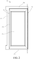
FIG. 1 is a three-dimensional schematic structural diagram of a door structure area of a household appliance according to an embodiment of the present invention; -
FIG. 2 is a schematic diagram of a main visual structure of an outer door of a household appliance according to an embodiment of the present invention; -
FIG. 3 is a three-dimensional schematic structural diagram of the top of an outer door of a household appliance according to an embodiment of the present invention; -
FIG. 4 is a three-dimensional schematic structural diagram of the bottom of an outer door of a household appliance according to an embodiment of the present invention; and -
FIG. 5 is a schematic sectional diagram of an outer door and an inner door that are superposed and that are of a household appliance on a side of a third protruding portion according to an embodiment of the present invention. - To make the foregoing objectives, features, and advantages of the present invention clearer and more comprehensible, the following describes specific embodiments of the present invention in detail with reference to the accompanying drawings.
- An embodiment of the present invention provides a household appliance, such as a refrigerator, as shown in
FIG. 1 , including: acase body 10 and a door structure rotatable around a rotation axis relative to thecase body 10. The door structure includes aninner door 20 and anouter door 30 that are superposed. Theouter door 30 is rotatably disposed before theinner door 20. A storage space is provided inside theinner door 20 to store articles, the storage space has an opening 20a towards theouter door 30, and theouter door 30 is used to open or close the opening 20a. - The
inner door 20 includes adoor body 21 surrounding the opening 20a, and thedoor body 21 may be filled with a foaming heat-insulation material. Thedoor body 21 of theinner door 20 is provided with ahandle portion 22, and thehandle portion 22 is provided with ahandle groove 22a. - In the present invention, "front" and "back" respectively indicate the front and the back along a front-back direction of the door.
- In this embodiment, the
outer door 30 has a heat-insulation portion 31 for closing theopening 20a. The heat-insulation portion 31 includes a heat-insulation glass module 31a, adoorframe 31b disposed around the heat-insulation glass module 31a, and afront door panel 32 disposed before thedoorframe 31b. Thedoorframe 31b includes several borders (not shown in the figure) that extend along a length direction and a width direction, and thefront door panel 32 is connected to front sides of the borders. The borders may be formed by means of a process such as an extrusion process or an injection molding process. Preferably, the border is an extrusion member. In some other embodiments, the heat-insulation portion may alternatively be a foaming door. Thefront door panel 32 is preferably a glass plate. - Referring to
FIG. 2 , thefront door panel 32 includes protrudingportions doorframe 31b along the length or width direction, and theouter door 30 further includescover members portions portions front door panel 32. That is, an area of thefront door panel 32 is greater than an area of an annular structure enclosed by thedoorframe 31b. A part of thefront door panel 32 that covers the annular structure enclosed by thedoorframe 31b may serve as a part of the heat-insulation portion 31, and a part of thefront door panel 32 that extends out of thedoorframe 31b forms the protrudingportions - In this embodiment, the protruding
portions portion 32a and a second protrudingportion 32b that extend out of two ends of thedoorframe 31b along a length direction (a height direction of the door inFIG. 1 ) of a rotation axis 00 of the outer door, and a third protrudingportion 32c that extends along a direction (a width direction of the door inFIG. 1 ) away from the rotation axis. A cover member is disposed behind each protruding portion. As shown inFIG. 1 . Thecover members first cover member 34a disposed behind the first protrudingportion 32a, asecond cover member 34b disposed behind the second protrudingportion 32b, and athird cover member 34c disposed behind the third protrudingportion 32c. - Each of the
cover members front door panel 32 or thedoorframe 31b. Preferably, each of thecover members front door panel 32 and thedoorframe 31b. For example, the cover member may be fixed on the doorframe by using a fixing structure, and at the same time, adhere to a rear surface of the front door panel. - The
first cover member 34a and thesecond cover member 34b are disposed at two ends of theouter door 30 along the length direction of the rotation axis 00. A side-opening door is used as an example. As shown inFIG. 1 , theinner door 20 and theouter door 30 in the door structure are both side-opening doors, the rotation axis 00 thereof extends along the height direction of the door, and thefirst cover member 34a and thesecond cover member 34b are respectively located at the top and bottom of theouter door 30, and each may be used to shield a part of a hinge installed on theouter door 30. - Advantages of this solution lie in: The front door panel extends out of the doorframe along the length or width direction and forms the protruding portion. The cover member is disposed behind each protruding portion. On one hand, the cover member can achieve an enhancing effect, to improve strength of the protruding portion and prevent the protruding portion from breaking. On the other hand, the cover member can achieve a covering effect, to cover some components, such as a hinge and a door handle, in the door structure. Therefore, structures of the inner door and the outer door may be more diversified, to ensure their functions, and at the time, meet an appearance requirement of industrial design.
- In the embodiments shown in
FIG. 1 andFIG. 2 , theouter door 30 is rotatably connected to theinner door 20 or thecase body 10 by usinghinges hinges outer door 30, and a second end is connected to theinner door 20, to limit the rotation axis 00 of theouter door 30. When theouter door 30 is a side-opening door, thehinge 41 is disposed at the top of thedoorframe 31b, and thehinge 42 is disposed at the bottom of thedoorframe 31b. Thefirst cover member 34a may shield a part of thehinge 41, and thesecond cover member 34b may shield a part of thehinge 42. - The hinges 41 and 42 each include the first end that extends to an end surface of the
doorframe 31b, and the first end may include a hinge shaft, to thread through a shaft hole of thedoorframe 31b, thereby fixing thehinges doorframe 31b. Along the length direction of the rotation axis 00, a projection of the first end coincides with a projection of thedoorframe 31b. The first protrudingportion 32a extends out of the top of thedoorframe 31b along a direction of the rotation axis 00, the first end of thehinge 41 is located behind the first protrudingportion 32a, and thefirst cover member 34a shields a part of or all of the first end of thehinge 41 at least on a side of thehinge 41 towards a door side surface. The second protrudingportion 32b extends out of the bottom of thedoorframe 31b along a direction of the rotation axis 00, the first end of thehinge 42 is located behind the second protrudingportion 32b, and thesecond cover member 34b shields a part of or all of the first end of thehinge 42 at least on a side of thehinge 42 towards a door side surface. - The "door side surface" is a surface of a door that extends along a thickness direction of the door among outer surfaces of the door, that is, a surface that extends along the front-back direction of the door.
- As shown in
FIG. 2 to FIG. 4 , thedoorframe 31b includes a first door side surface S1 and a second door side surface S2 opposite to each other that are arranged along a direction perpendicular to a length direction of the rotation axis 00, the second door side surface S2 is closer to the rotation axis 00 than the first door side surface S1, and the second door side surface S2 is located at a free end of theouter door 30. The first door side surface S1 and the second door side surface S2 are located two sides along a length direction of the first protrudingportion 32a and the second protrudingportion 32b. In addition, as shown inFIG. 3 and FIG. 4 (the front door panel is not shown inFIG. 3 and FIG. 4 ), thefirst cover member 34a and thesecond cover member 34b extend from the first door side surface S1 to the second door side surface S2 along a width direction of the door. - As shown in
FIG. 3 , an accommodating cavity C for accommodating the first end of thehinge 41 is formed behind the first protrudingportion 32a at the top of theouter door 30, the first end of thehinge 41 extends into the accommodating cavity C, and a shaft hole at the top of theouter door 30 that is used for connecting to thehinge 41 is exposed in the accommodating cavity C. When theouter door 30 is open, an area that is occupied by the first end of thehinge 41 that extends into the accommodating cavity C is relatively small; and when theouter door 30 is closed, an area that is occupied by the first end of thehinge 41 that extends into the accommodating cavity C is relatively large. The accommodating cavity C may be directly formed in thefirst cover member 34a, or in some other embodiments, the accommodating cavity C may be jointly enclosed by thefirst cover member 34a, thedoorframe 31b, and the first protrudingportion 32a, or may be enclosed by thefirst cover member 34a and the first protrudingportion 32a. - The accommodating cavity C of the
first cover member 34a has a first shielding wall W1 towards thehinge 41, the first shielding wall W1 is located on a side of thehinge 41 towards the first door side surface S1, and the first shielding wall W1 is located between the first door side surface S1 and the rotation axis 00 along the width direction of the door. Along a direction from the first door side surface S1 to the second door side surface S2, the first end of thehinge 41 is shielded by the first shielding wall W1. Therefore, from the perspective of a free end of theouter door 30, the first end of thehinge 41 is shielded by the first shielding wall W1, to be hidden from the sight of a user. - The accommodating cavity C of the
first cover member 34a further has a second shielding wall W2 towards thehinge 41, the second shielding wall W2 is located on a side of thehinge 41 towards the second door side surface S2, and the second shielding wall W2 is located between the second door side surface S2 and the rotation axis 00 along the width direction of the door. Along a direction from the second door side surface S2 to the first door side surface S1, the first end of thehinge 41 is shielded by the second shielding wall W2. Therefore, from the perspective of the rotation axis 00 of theouter door 30, the first end of thehinge 41 is shielded by the second shielding wall W2, to be hidden from the sight of the user. - It can be seen that, along the width direction of the door, the first end of the
hinge 41 is located between the first shielding wall W1 and the second shielding wall W2, and is separately shielded by the first shielding wall W1 and the second shielding wall W2. Therefore, from the width direction of the door, the first end of thehinge 41 is hidden in the accommodating cavity C. - It should be understood that, to ensure the aesthetic of the
outer door 30 on the first door side surface S1 and the second door side surface S2, a side of thefirst cover member 34a on the second door side surface S2 is flush with the second door side surface S2, and a side on the first door side surface S1 is flush with the first door side surface S1. - Further, the
first cover member 34a further has a third shielding wall W3 towards thehinge 41, the third shielding wall W3 is located on a side of thehinge 41 opposite to thedoorframe 31b, and the third shielding wall W3 serves as a top wall of the accommodating cavity C, to shield, at the top of theouter door 30, the first end of thehinge 41. Therefore, from the perspective of the top of theouter door 30, the first end of thehinge 41 is hidden behind the third shielding wall W3. - It can be seen that, along the height direction of the door, the first end of the
hinge 41 is located between the third shielding wall W3 and the end surface of thedoorframe 31b. Therefore, from the height direction of the door, the first end of thehinge 41 is hidden in the accommodating cavity C. - It should be understood that, to ensure the aesthetic of the
outer door 30 at the top, thefirst cover member 34a and the first protrudingportion 32a are flush with each other on a side opposite to thedoorframe 31b, and a top surface of thefirst cover member 34a serves as a side surface at the top of the outer door. - The shape of the
second cover member 34b of theouter door 30 that is located behind the second protrudingportion 32b may be set by referring to that of thefirst cover member 34a. When theouter door 30 is a door that turns upwards or downwards, a structure of thesecond cover member 34b and a structure of thefirst cover member 34a are preferably set to be consistent with each other. Therefore, hinges on both sides can be effectively shielded. - In this embodiment, the
second cover member 34b is disposed at the bottom of theouter door 30, and a probability for thehinge 42 at the bottom to be exposed to a visual field of the user is relatively small. Therefore, a structure of thesecond cover member 34b may be different from a structure of thefirst cover member 34a. As shown inFIG. 4 , thesecond cover member 34b includes the first shielding wall W1, and the first shielding wall W1 is formed by an end surface of thesecond cover member 34b. The first shielding wall W1 includes two interconnected parts. The first part W11 extends along a thickness direction of theouter door 30, and the second part W12 extends along a direction from the first door side surface S1 to the second door side surface S2. Preferably, the first part W11 and the second part W12 have a smooth transition, that is, a connection corner between the two pars is round. - As shown in
FIG. 4 , in thesecond cover member 34b, there is no shielding wall for shielding thehinge 42 other than the first shielding wall W1. - As shown in
FIG. 1 and with reference toFIG. 2 andFIG. 5 , thethird cover member 34c is disposed on a side of theouter door 30 away from the rotation axis 00 of theouter door 30. Ahandle portion 22 of the inner door is provided at the back of the third protrudingportion 32c. In this embodiment, thethird cover member 34c is a protective plate connected to a rear surface of the third protrudingportion 32c to shield the rear surface, and there is a spacing between thehandle portion 22 and the third protrudingportion 32c along the front-back direction of the door, to prevent thehandle portion 22 and thethird cover member 34c from collision. Thethird cover member 34c is fixed to thedoorframe 31 b. Therefore, when the user applies force to thethird cover member 34c, at least a part of the force may be shared by thedoorframe 31 b. Preferably, thethird cover member 34c adheres to the rear surface of the third protrudingportion 32c. - In some other embodiments, the third cover member may alternatively be a frame structure or another structure, and the handle portion of the outer door may be directly integrated into the third cover member.
- It should be understood that, the structure of the
outer door 30 may alternatively be used in a refrigerator with a single-layer door structure in which the inner door is omitted and theouter door 30 is directly connected to the case body by using thehinges - In addition, the household appliance in this embodiment is not limited to a refrigerator, and may also be an electrical appliance, such as an oven, a microwave oven, or a disinfection cabinet, that has a storage space and is closed by using a door structure. The door structure may include only the
outer door 30 or include both theinner door 20 and theouter door 30. - Although the present invention has been disclosed above, the present invention is not limited thereto. Any person skilled in the art may make various variations or modifications without departing from the spirit and the scope of the present invention. Therefore, the protection scope of the present invention shall be subject to the scope of the claims.
Claims (22)
- A household appliance, comprising a case body (10) and a door (30) rotatable around a rotation axis (00) relative to the case body (10), wherein the door (30) comprises a doorframe (31b) and a front door panel (32) connected to a front side of the doorframe (31b), characterized in that
the front door panel (32) comprises a protruding portion (32a, 32b, 32c) that extends out of the doorframe (31b) along a length or width direction of the door, and the door further comprises a cover member (34a, 34b, 34c) disposed behind the protruding portion (32a, 32b, 32c). - The household appliance according to claim 1, characterized in that the cover member (34a, 34b, 34c) is fixed on at least one of the front door panel (32) or the doorframe (31b).
- The household appliance according to claim 1 or 2, characterized by further comprising a hinge (41, 42) for limiting the rotation axis (00), wherein the hinge (41, 42) comprises a first end disposed on an end surface of the doorframe (31b); and
the protruding portion (32a, 32b, 32c) extends out of the doorframe (31b) along a direction of the rotation axis (00), the first end of the hinge (41, 42) is located behind the protruding portion (32a, 32b, 32c), and the cover member (34a, 34b, 34c) shields the first end at least on a side of the hinge (41, 42) towards a door side surface. - The household appliance according to claim 3, characterized in that the doorframe (31b) comprises a first door side surface (S1) and a second door side surface (S2) opposite to each other that are arranged along a direction perpendicular to a length direction of the rotation axis (00), and the second door side surface (S2) is closer to the rotation axis (00) than the first door side surface (S1); and
the cover member (34a, 34b, 34c) has a first shielding wall (W1) towards the hinge (41, 42), and the first shielding wall (W1) is located on a side of the hinge (41, 42) towards the first door side surface (S1). - The household appliance according to claim 4, characterized in that the first shielding wall (W1) is formed by an end surface of the cover member (34a, 34b, 34c).
- The household appliance according to claim 4 or 5, characterized in that the first shielding wall (W1) comprises two parts connected to each other, one part extends along a thickness direction of the door, and the other part extends along a direction from the first door side surface (S1) to the second door side surface (S2).
- The household appliance according to claim 6, characterized in that the two parts have a smooth transition.
- The household appliance according to one of the claims 3 to 7, characterized in that the doorframe (31b) comprises a first door side surface (S1) and a second door side surface (S2) opposite to each other that are arranged along a direction perpendicular to a length direction of the rotation axis (00), and the second door side surface (S2) is closer to the rotation axis (00) than the first door side surface (S1); and
the cover member (34a, 34b, 34c) has a second shielding wall (W2) towards the hinge (41, 42), and the second shielding wall (W2) is located on a side of the hinge (41, 42) towards the second door side surface (S2). - The household appliance according to claim 8, characterized in that the second shielding wall (W2) is flush with the second door side surface (S2).
- The household appliance according to one of the claims 3 to 9, characterized in that the cover member (34a, 34b, 34c) has a third shielding wall (W3) towards the hinge (41, 42), and the third shielding wall (W3) is located on a side of the hinge (41, 42) opposite to the doorframe (31b).
- The household appliance according to one of the preceding claims, characterized in that the cover member (34a, 34b, 34c) and the protruding portion (32a, 32b, 32c) are flush with each other on a side opposite to the doorframe (31b).
- The household appliance according to one of the claims 3 to 11, characterized in that the first end of the hinge (41, 42) is fixed to the doorframe (31b).
- The household appliance according to one of the preceding claims, characterized in that the cover member (34a, 34b, 34c) adheres to a rear side of the protruding portion (32a, 32b, 32c).
- The household appliance according to one of the preceding claims, characterized in that the cover member (34a, 34b, 34c) is fixed to the doorframe (31b).
- The household appliance according to one of the preceding claims, characterized in that the doorframe (31b) comprises two door side surfaces (S1, S2) located on two sides along a length direction of the protruding portion (32a, 32b, 32c), and the cover member (34a, 34b, 34c) extends from the door side surface (S1) to the other door side surface (S2).
- The household appliance according to one of the preceding claims, characterized in that the cover member (34a, 34b, 34c) is provided with a handle portion (22); or
a handle portion (22) is provided at the back of the protruding portion (32a, 32b, 32c), and the cover member (34a, 34b, 34c) is located between the handle portion (22) and the protruding portion (32a, 32b, 32c). - The household appliance according to one of the preceding claims, characterized in that the cover member (34a, 34b, 34c) is a protective plate (34c) connected to a rear surface of the protruding portion (32a, 32b, 32c) to shield the rear surface.
- The household appliance according to one of the preceding claims, characterized in that the doorframe (31b) comprises at least one border having a heat-insulation cavity inside, and the front door panel (32) is connected to a front side of the border.
- The household appliance according to claim 18, characterized in that the border is an extrusion member.
- The household appliance according to one of the preceding claims, characterized in that the front door panel (32) is a glass plate.
- The household appliance according to one of the preceding claims, characterized in that the door (30) further comprises a heat-insulation glass module (31a), and the doorframe (31b) surrounds the heat-insulation glass module (31a).
- The household appliance according to one of the preceding claims, characterized by further comprising an inner door (20) rotatably connected to the case body (10), wherein the door (30) is rotatable relative to the inner door (20).
Applications Claiming Priority (1)
| Application Number | Priority Date | Filing Date | Title |
|---|---|---|---|
| CN201611253871.XA CN108253708A (en) | 2016-12-29 | 2016-12-29 | Household electrical appliance |
Publications (2)
| Publication Number | Publication Date |
|---|---|
| EP3343151A1 true EP3343151A1 (en) | 2018-07-04 |
| EP3343151B1 EP3343151B1 (en) | 2022-08-17 |
Family
ID=60702351
Family Applications (1)
| Application Number | Title | Priority Date | Filing Date |
|---|---|---|---|
| EP17208882.5A Active EP3343151B1 (en) | 2016-12-29 | 2017-12-20 | Household appliance |
Country Status (3)
| Country | Link |
|---|---|
| US (1) | US10724784B2 (en) |
| EP (1) | EP3343151B1 (en) |
| CN (1) | CN108253708A (en) |
Cited By (2)
| Publication number | Priority date | Publication date | Assignee | Title |
|---|---|---|---|---|
| CN111631564A (en) * | 2020-06-10 | 2020-09-08 | 北京英博伦科技发展有限公司 | Flat-open type cultural relic showcase |
| US10823485B2 (en) * | 2016-12-29 | 2020-11-03 | Bsh Hausgeraete Gmbh | Refrigerator |
Families Citing this family (5)
| Publication number | Priority date | Publication date | Assignee | Title |
|---|---|---|---|---|
| CN108613462A (en) * | 2016-12-12 | 2018-10-02 | 博西华电器(江苏)有限公司 | Refrigerating appliance and its insulated door |
| CN112144249B (en) * | 2019-06-27 | 2023-11-17 | 博西华电器(江苏)有限公司 | Laundry appliance |
| US11215391B1 (en) | 2020-12-01 | 2022-01-04 | Electrolux Home Products, Inc. | Staged access door for a home appliance |
| US11668513B2 (en) | 2020-12-01 | 2023-06-06 | Electrolux Home Products, Inc. | Staged access door for a home appliance |
| CN114961471B (en) * | 2021-02-26 | 2023-10-27 | 青岛海尔电冰箱有限公司 | Hinge assembly with shielding part and refrigeration equipment with hinge assembly |
Citations (3)
| Publication number | Priority date | Publication date | Assignee | Title |
|---|---|---|---|---|
| WO2004106823A1 (en) * | 2003-06-02 | 2004-12-09 | BSH Bosch und Siemens Hausgeräte GmbH | Door comprising insulating glazing and refrigerating appliance fitted therewith |
| WO2004105558A1 (en) * | 2003-06-02 | 2004-12-09 | BSH Bosch und Siemens Hausgeräte GmbH | Door comprising an insulating glazing and electric household appliance provided with said door |
| EP3086061A1 (en) * | 2014-10-17 | 2016-10-26 | LG Electronics Inc. | Refrigerator |
Family Cites Families (14)
| Publication number | Priority date | Publication date | Assignee | Title |
|---|---|---|---|---|
| US5048233A (en) * | 1987-05-01 | 1991-09-17 | Northland Corporation | Refrigerator door and method of manufacturing same |
| JP4147138B2 (en) * | 2003-04-04 | 2008-09-10 | ホシザキ電機株式会社 | Storage |
| AU2006352109B2 (en) * | 2006-12-21 | 2010-07-01 | Lg Electronics Inc. | A door support device for refrigerator and refrigerator comprising the same |
| CN101086194A (en) * | 2007-07-03 | 2007-12-12 | 海尔集团公司 | All-purpose refrigerator threading hinge |
| CN102116554A (en) * | 2010-01-04 | 2011-07-06 | Lg电子株式会社 | Refrigerator |
| US20120080990A1 (en) * | 2010-10-04 | 2012-04-05 | Matthew William Davis | Top-loaded refrigerator doors |
| KR102025734B1 (en) * | 2012-11-09 | 2019-09-27 | 삼성전자주식회사 | Refrigerator and method of making the inner door thereof |
| KR102025177B1 (en) * | 2012-11-09 | 2019-09-26 | 삼성전자주식회사 | Refrigerator and method of making the inner door thereof |
| EP3008408B1 (en) * | 2013-06-14 | 2021-02-24 | LG Electronics Inc. | Refrigerator |
| KR102234011B1 (en) * | 2014-02-17 | 2021-03-29 | 엘지전자 주식회사 | Refrigerator |
| US9605891B2 (en) * | 2014-03-11 | 2017-03-28 | Samsung Electronics Co., Ltd. | Refrigerator |
| KR101691260B1 (en) * | 2014-10-17 | 2016-12-29 | 엘지전자 주식회사 | Refrigerator |
| CN204535247U (en) * | 2015-01-05 | 2015-08-05 | 青岛海尔股份有限公司 | Door body and there is the refrigerating device of this body |
| CN205370286U (en) * | 2015-12-30 | 2016-07-06 | 博西华电器(江苏)有限公司 | Domestic appliance and door thereof |
-
2016
- 2016-12-29 CN CN201611253871.XA patent/CN108253708A/en active Pending
-
2017
- 2017-12-20 EP EP17208882.5A patent/EP3343151B1/en active Active
- 2017-12-28 US US15/856,286 patent/US10724784B2/en active Active
Patent Citations (3)
| Publication number | Priority date | Publication date | Assignee | Title |
|---|---|---|---|---|
| WO2004106823A1 (en) * | 2003-06-02 | 2004-12-09 | BSH Bosch und Siemens Hausgeräte GmbH | Door comprising insulating glazing and refrigerating appliance fitted therewith |
| WO2004105558A1 (en) * | 2003-06-02 | 2004-12-09 | BSH Bosch und Siemens Hausgeräte GmbH | Door comprising an insulating glazing and electric household appliance provided with said door |
| EP3086061A1 (en) * | 2014-10-17 | 2016-10-26 | LG Electronics Inc. | Refrigerator |
Cited By (2)
| Publication number | Priority date | Publication date | Assignee | Title |
|---|---|---|---|---|
| US10823485B2 (en) * | 2016-12-29 | 2020-11-03 | Bsh Hausgeraete Gmbh | Refrigerator |
| CN111631564A (en) * | 2020-06-10 | 2020-09-08 | 北京英博伦科技发展有限公司 | Flat-open type cultural relic showcase |
Also Published As
| Publication number | Publication date |
|---|---|
| US20180187953A1 (en) | 2018-07-05 |
| EP3343151B1 (en) | 2022-08-17 |
| CN108253708A (en) | 2018-07-06 |
| US10724784B2 (en) | 2020-07-28 |
Similar Documents
| Publication | Publication Date | Title |
|---|---|---|
| EP3343151A1 (en) | Household appliances | |
| AU2011354119B2 (en) | Built-in electrical household appliance and household appliance assembly and built-in furniture unit for a household appliance | |
| US10208963B2 (en) | Cooking appliance | |
| US10465969B2 (en) | Refrigerator | |
| EP3169957B1 (en) | Door for refrigerator and refrigerator | |
| US20100244646A1 (en) | Refrigeration unit with framed door | |
| CN111998607B (en) | User interface unit for a refrigeration device and refrigeration device | |
| US20180164022A1 (en) | Heat insulation door and refrigeration appliance with the heat insulation door | |
| EP3169955A1 (en) | Refrigerator | |
| KR102271280B1 (en) | Inner door assembly and Door for drum type washing machine, and Drum type washing machine having the same | |
| CN105063971B (en) | For the housing unit and washing machine of washing machine | |
| KR20180105929A (en) | Refrigerator | |
| KR101586588B1 (en) | Refrigerator and method for manufacturing thereof | |
| US10418790B2 (en) | Housing | |
| KR101758078B1 (en) | Vertical frame for door frame | |
| CN206591321U (en) | Door closure component and rotary drum washing machine for rotary drum washing machine | |
| CN208725513U (en) | A kind of door body structure of household electrical appliance | |
| JPH0961046A (en) | Door of refrigerator | |
| CN218380095U (en) | Hidden handle structure suitable for embedded wine cabinet | |
| KR100398485B1 (en) | Door of micro wave oven | |
| EP2554735B1 (en) | A top-loading washing machine comprising a pivoting lid | |
| KR102185719B1 (en) | refrigerator | |
| JPH0620068Y2 (en) | Door opening / closing device for storage | |
| KR20210156172A (en) | Refrigerator | |
| JP2016054243A (en) | Electronics housing box |
Legal Events
| Date | Code | Title | Description |
|---|---|---|---|
| PUAI | Public reference made under article 153(3) epc to a published international application that has entered the european phase |
Free format text: ORIGINAL CODE: 0009012 |
|
| STAA | Information on the status of an ep patent application or granted ep patent |
Free format text: STATUS: THE APPLICATION HAS BEEN PUBLISHED |
|
| AK | Designated contracting states |
Kind code of ref document: A1 Designated state(s): AL AT BE BG CH CY CZ DE DK EE ES FI FR GB GR HR HU IE IS IT LI LT LU LV MC MK MT NL NO PL PT RO RS SE SI SK SM TR |
|
| AX | Request for extension of the european patent |
Extension state: BA ME |
|
| STAA | Information on the status of an ep patent application or granted ep patent |
Free format text: STATUS: REQUEST FOR EXAMINATION WAS MADE |
|
| 17P | Request for examination filed |
Effective date: 20190104 |
|
| RBV | Designated contracting states (corrected) |
Designated state(s): AL AT BE BG CH CY CZ DE DK EE ES FI FR GB GR HR HU IE IS IT LI LT LU LV MC MK MT NL NO PL PT RO RS SE SI SK SM TR |
|
| STAA | Information on the status of an ep patent application or granted ep patent |
Free format text: STATUS: EXAMINATION IS IN PROGRESS |
|
| STAA | Information on the status of an ep patent application or granted ep patent |
Free format text: STATUS: EXAMINATION IS IN PROGRESS |
|
| 17Q | First examination report despatched |
Effective date: 20201012 |
|
| GRAP | Despatch of communication of intention to grant a patent |
Free format text: ORIGINAL CODE: EPIDOSNIGR1 |
|
| STAA | Information on the status of an ep patent application or granted ep patent |
Free format text: STATUS: GRANT OF PATENT IS INTENDED |
|
| RIC1 | Information provided on ipc code assigned before grant |
Ipc: F25D 23/02 20060101AFI20211104BHEP |
|
| INTG | Intention to grant announced |
Effective date: 20211208 |
|
| GRAJ | Information related to disapproval of communication of intention to grant by the applicant or resumption of examination proceedings by the epo deleted |
Free format text: ORIGINAL CODE: EPIDOSDIGR1 |
|
| STAA | Information on the status of an ep patent application or granted ep patent |
Free format text: STATUS: EXAMINATION IS IN PROGRESS |
|
| GRAP | Despatch of communication of intention to grant a patent |
Free format text: ORIGINAL CODE: EPIDOSNIGR1 |
|
| INTC | Intention to grant announced (deleted) | ||
| STAA | Information on the status of an ep patent application or granted ep patent |
Free format text: STATUS: GRANT OF PATENT IS INTENDED |
|
| INTG | Intention to grant announced |
Effective date: 20220407 |
|
| GRAS | Grant fee paid |
Free format text: ORIGINAL CODE: EPIDOSNIGR3 |
|
| GRAA | (expected) grant |
Free format text: ORIGINAL CODE: 0009210 |
|
| STAA | Information on the status of an ep patent application or granted ep patent |
Free format text: STATUS: THE PATENT HAS BEEN GRANTED |
|
| AK | Designated contracting states |
Kind code of ref document: B1 Designated state(s): AL AT BE BG CH CY CZ DE DK EE ES FI FR GB GR HR HU IE IS IT LI LT LU LV MC MK MT NL NO PL PT RO RS SE SI SK SM TR |
|
| REG | Reference to a national code |
Ref country code: CH Ref legal event code: EP |
|
| REG | Reference to a national code |
Ref country code: DE Ref legal event code: R096 Ref document number: 602017060699 Country of ref document: DE |
|
| REG | Reference to a national code |
Ref country code: IE Ref legal event code: FG4D |
|
| REG | Reference to a national code |
Ref country code: AT Ref legal event code: REF Ref document number: 1512436 Country of ref document: AT Kind code of ref document: T Effective date: 20220915 |
|
| REG | Reference to a national code |
Ref country code: NL Ref legal event code: MP Effective date: 20220817 |
|
| REG | Reference to a national code |
Ref country code: LT Ref legal event code: MG9D |
|
| PG25 | Lapsed in a contracting state [announced via postgrant information from national office to epo] |
Ref country code: SE Free format text: LAPSE BECAUSE OF FAILURE TO SUBMIT A TRANSLATION OF THE DESCRIPTION OR TO PAY THE FEE WITHIN THE PRESCRIBED TIME-LIMIT Effective date: 20220817 Ref country code: RS Free format text: LAPSE BECAUSE OF FAILURE TO SUBMIT A TRANSLATION OF THE DESCRIPTION OR TO PAY THE FEE WITHIN THE PRESCRIBED TIME-LIMIT Effective date: 20220817 Ref country code: PT Free format text: LAPSE BECAUSE OF FAILURE TO SUBMIT A TRANSLATION OF THE DESCRIPTION OR TO PAY THE FEE WITHIN THE PRESCRIBED TIME-LIMIT Effective date: 20221219 Ref country code: NO Free format text: LAPSE BECAUSE OF FAILURE TO SUBMIT A TRANSLATION OF THE DESCRIPTION OR TO PAY THE FEE WITHIN THE PRESCRIBED TIME-LIMIT Effective date: 20221117 Ref country code: NL Free format text: LAPSE BECAUSE OF FAILURE TO SUBMIT A TRANSLATION OF THE DESCRIPTION OR TO PAY THE FEE WITHIN THE PRESCRIBED TIME-LIMIT Effective date: 20220817 Ref country code: LV Free format text: LAPSE BECAUSE OF FAILURE TO SUBMIT A TRANSLATION OF THE DESCRIPTION OR TO PAY THE FEE WITHIN THE PRESCRIBED TIME-LIMIT Effective date: 20220817 Ref country code: LT Free format text: LAPSE BECAUSE OF FAILURE TO SUBMIT A TRANSLATION OF THE DESCRIPTION OR TO PAY THE FEE WITHIN THE PRESCRIBED TIME-LIMIT Effective date: 20220817 Ref country code: FI Free format text: LAPSE BECAUSE OF FAILURE TO SUBMIT A TRANSLATION OF THE DESCRIPTION OR TO PAY THE FEE WITHIN THE PRESCRIBED TIME-LIMIT Effective date: 20220817 |
|
| PGFP | Annual fee paid to national office [announced via postgrant information from national office to epo] |
Ref country code: DE Payment date: 20221231 Year of fee payment: 6 |
|
| REG | Reference to a national code |
Ref country code: AT Ref legal event code: MK05 Ref document number: 1512436 Country of ref document: AT Kind code of ref document: T Effective date: 20220817 |
|
| PG25 | Lapsed in a contracting state [announced via postgrant information from national office to epo] |
Ref country code: PL Free format text: LAPSE BECAUSE OF FAILURE TO SUBMIT A TRANSLATION OF THE DESCRIPTION OR TO PAY THE FEE WITHIN THE PRESCRIBED TIME-LIMIT Effective date: 20220817 Ref country code: IS Free format text: LAPSE BECAUSE OF FAILURE TO SUBMIT A TRANSLATION OF THE DESCRIPTION OR TO PAY THE FEE WITHIN THE PRESCRIBED TIME-LIMIT Effective date: 20221217 Ref country code: HR Free format text: LAPSE BECAUSE OF FAILURE TO SUBMIT A TRANSLATION OF THE DESCRIPTION OR TO PAY THE FEE WITHIN THE PRESCRIBED TIME-LIMIT Effective date: 20220817 Ref country code: GR Free format text: LAPSE BECAUSE OF FAILURE TO SUBMIT A TRANSLATION OF THE DESCRIPTION OR TO PAY THE FEE WITHIN THE PRESCRIBED TIME-LIMIT Effective date: 20221118 |
|
| PG25 | Lapsed in a contracting state [announced via postgrant information from national office to epo] |
Ref country code: SM Free format text: LAPSE BECAUSE OF FAILURE TO SUBMIT A TRANSLATION OF THE DESCRIPTION OR TO PAY THE FEE WITHIN THE PRESCRIBED TIME-LIMIT Effective date: 20220817 Ref country code: RO Free format text: LAPSE BECAUSE OF FAILURE TO SUBMIT A TRANSLATION OF THE DESCRIPTION OR TO PAY THE FEE WITHIN THE PRESCRIBED TIME-LIMIT Effective date: 20220817 Ref country code: ES Free format text: LAPSE BECAUSE OF FAILURE TO SUBMIT A TRANSLATION OF THE DESCRIPTION OR TO PAY THE FEE WITHIN THE PRESCRIBED TIME-LIMIT Effective date: 20220817 Ref country code: DK Free format text: LAPSE BECAUSE OF FAILURE TO SUBMIT A TRANSLATION OF THE DESCRIPTION OR TO PAY THE FEE WITHIN THE PRESCRIBED TIME-LIMIT Effective date: 20220817 Ref country code: CZ Free format text: LAPSE BECAUSE OF FAILURE TO SUBMIT A TRANSLATION OF THE DESCRIPTION OR TO PAY THE FEE WITHIN THE PRESCRIBED TIME-LIMIT Effective date: 20220817 Ref country code: AT Free format text: LAPSE BECAUSE OF FAILURE TO SUBMIT A TRANSLATION OF THE DESCRIPTION OR TO PAY THE FEE WITHIN THE PRESCRIBED TIME-LIMIT Effective date: 20220817 |
|
| REG | Reference to a national code |
Ref country code: DE Ref legal event code: R097 Ref document number: 602017060699 Country of ref document: DE |
|
| PG25 | Lapsed in a contracting state [announced via postgrant information from national office to epo] |
Ref country code: SK Free format text: LAPSE BECAUSE OF FAILURE TO SUBMIT A TRANSLATION OF THE DESCRIPTION OR TO PAY THE FEE WITHIN THE PRESCRIBED TIME-LIMIT Effective date: 20220817 Ref country code: EE Free format text: LAPSE BECAUSE OF FAILURE TO SUBMIT A TRANSLATION OF THE DESCRIPTION OR TO PAY THE FEE WITHIN THE PRESCRIBED TIME-LIMIT Effective date: 20220817 |
|
| PLBE | No opposition filed within time limit |
Free format text: ORIGINAL CODE: 0009261 |
|
| STAA | Information on the status of an ep patent application or granted ep patent |
Free format text: STATUS: NO OPPOSITION FILED WITHIN TIME LIMIT |
|
| PG25 | Lapsed in a contracting state [announced via postgrant information from national office to epo] |
Ref country code: AL Free format text: LAPSE BECAUSE OF FAILURE TO SUBMIT A TRANSLATION OF THE DESCRIPTION OR TO PAY THE FEE WITHIN THE PRESCRIBED TIME-LIMIT Effective date: 20220817 |
|
| 26N | No opposition filed |
Effective date: 20230519 |
|
| REG | Reference to a national code |
Ref country code: CH Ref legal event code: PL |
|
| GBPC | Gb: european patent ceased through non-payment of renewal fee |
Effective date: 20221220 |
|
| REG | Reference to a national code |
Ref country code: BE Ref legal event code: MM Effective date: 20221231 |
|
| PG25 | Lapsed in a contracting state [announced via postgrant information from national office to epo] |
Ref country code: SI Free format text: LAPSE BECAUSE OF FAILURE TO SUBMIT A TRANSLATION OF THE DESCRIPTION OR TO PAY THE FEE WITHIN THE PRESCRIBED TIME-LIMIT Effective date: 20220817 Ref country code: LU Free format text: LAPSE BECAUSE OF NON-PAYMENT OF DUE FEES Effective date: 20221220 |
|
| PG25 | Lapsed in a contracting state [announced via postgrant information from national office to epo] |
Ref country code: LI Free format text: LAPSE BECAUSE OF NON-PAYMENT OF DUE FEES Effective date: 20221231 Ref country code: IE Free format text: LAPSE BECAUSE OF NON-PAYMENT OF DUE FEES Effective date: 20221220 Ref country code: GB Free format text: LAPSE BECAUSE OF NON-PAYMENT OF DUE FEES Effective date: 20221220 Ref country code: CH Free format text: LAPSE BECAUSE OF NON-PAYMENT OF DUE FEES Effective date: 20221231 |
|
| PG25 | Lapsed in a contracting state [announced via postgrant information from national office to epo] |
Ref country code: FR Free format text: LAPSE BECAUSE OF NON-PAYMENT OF DUE FEES Effective date: 20221231 Ref country code: BE Free format text: LAPSE BECAUSE OF NON-PAYMENT OF DUE FEES Effective date: 20221231 |
|
| PG25 | Lapsed in a contracting state [announced via postgrant information from national office to epo] |
Ref country code: HU Free format text: LAPSE BECAUSE OF FAILURE TO SUBMIT A TRANSLATION OF THE DESCRIPTION OR TO PAY THE FEE WITHIN THE PRESCRIBED TIME-LIMIT; INVALID AB INITIO Effective date: 20171220 |