EP3343040A1 - Rotary compressor and freezing circulation device having same - Google Patents
Rotary compressor and freezing circulation device having same Download PDFInfo
- Publication number
- EP3343040A1 EP3343040A1 EP15901940.5A EP15901940A EP3343040A1 EP 3343040 A1 EP3343040 A1 EP 3343040A1 EP 15901940 A EP15901940 A EP 15901940A EP 3343040 A1 EP3343040 A1 EP 3343040A1
- Authority
- EP
- European Patent Office
- Prior art keywords
- sliding vane
- gas injection
- rotary compressor
- cylinder
- injection hole
- Prior art date
- Legal status (The legal status is an assumption and is not a legal conclusion. Google has not performed a legal analysis and makes no representation as to the accuracy of the status listed.)
- Granted
Links
- 230000008014 freezing Effects 0.000 title 1
- 238000007710 freezing Methods 0.000 title 1
- 238000002347 injection Methods 0.000 claims abstract description 91
- 239000007924 injection Substances 0.000 claims abstract description 91
- 230000006835 compression Effects 0.000 claims abstract description 63
- 238000007906 compression Methods 0.000 claims abstract description 63
- 238000004891 communication Methods 0.000 claims abstract description 38
- 239000003507 refrigerant Substances 0.000 claims abstract description 27
- 239000007788 liquid Substances 0.000 claims abstract description 26
- 238000005057 refrigeration Methods 0.000 claims abstract description 20
- 230000007246 mechanism Effects 0.000 claims abstract description 15
- 238000005192 partition Methods 0.000 claims description 18
- 238000005096 rolling process Methods 0.000 claims description 12
- 238000010438 heat treatment Methods 0.000 description 7
- 230000000694 effects Effects 0.000 description 6
- 238000000034 method Methods 0.000 description 5
- 230000008569 process Effects 0.000 description 5
- 239000000463 material Substances 0.000 description 4
- 238000001704 evaporation Methods 0.000 description 3
- 239000000243 solution Substances 0.000 description 3
- 230000009471 action Effects 0.000 description 2
- 238000006073 displacement reaction Methods 0.000 description 2
- 230000008020 evaporation Effects 0.000 description 2
- 238000005516 engineering process Methods 0.000 description 1
- 239000010687 lubricating oil Substances 0.000 description 1
- 238000003754 machining Methods 0.000 description 1
- 239000000203 mixture Substances 0.000 description 1
- 238000012986 modification Methods 0.000 description 1
- 230000004048 modification Effects 0.000 description 1
- 239000010726 refrigerant oil Substances 0.000 description 1
- 238000000926 separation method Methods 0.000 description 1
- 230000003068 static effect Effects 0.000 description 1
Images


Classifications
-
- F—MECHANICAL ENGINEERING; LIGHTING; HEATING; WEAPONS; BLASTING
- F04—POSITIVE - DISPLACEMENT MACHINES FOR LIQUIDS; PUMPS FOR LIQUIDS OR ELASTIC FLUIDS
- F04C—ROTARY-PISTON, OR OSCILLATING-PISTON, POSITIVE-DISPLACEMENT MACHINES FOR LIQUIDS; ROTARY-PISTON, OR OSCILLATING-PISTON, POSITIVE-DISPLACEMENT PUMPS
- F04C23/00—Combinations of two or more pumps, each being of rotary-piston or oscillating-piston type, specially adapted for elastic fluids; Pumping installations specially adapted for elastic fluids; Multi-stage pumps specially adapted for elastic fluids
- F04C23/001—Combinations of two or more pumps, each being of rotary-piston or oscillating-piston type, specially adapted for elastic fluids; Pumping installations specially adapted for elastic fluids; Multi-stage pumps specially adapted for elastic fluids of similar working principle
-
- F—MECHANICAL ENGINEERING; LIGHTING; HEATING; WEAPONS; BLASTING
- F04—POSITIVE - DISPLACEMENT MACHINES FOR LIQUIDS; PUMPS FOR LIQUIDS OR ELASTIC FLUIDS
- F04C—ROTARY-PISTON, OR OSCILLATING-PISTON, POSITIVE-DISPLACEMENT MACHINES FOR LIQUIDS; ROTARY-PISTON, OR OSCILLATING-PISTON, POSITIVE-DISPLACEMENT PUMPS
- F04C18/00—Rotary-piston pumps specially adapted for elastic fluids
- F04C18/30—Rotary-piston pumps specially adapted for elastic fluids having the characteristics covered by two or more of groups F04C18/02, F04C18/08, F04C18/22, F04C18/24, F04C18/48, or having the characteristics covered by one of these groups together with some other type of movement between co-operating members
- F04C18/34—Rotary-piston pumps specially adapted for elastic fluids having the characteristics covered by two or more of groups F04C18/02, F04C18/08, F04C18/22, F04C18/24, F04C18/48, or having the characteristics covered by one of these groups together with some other type of movement between co-operating members having the movement defined in group F04C18/08 or F04C18/22 and relative reciprocation between the co-operating members
- F04C18/356—Rotary-piston pumps specially adapted for elastic fluids having the characteristics covered by two or more of groups F04C18/02, F04C18/08, F04C18/22, F04C18/24, F04C18/48, or having the characteristics covered by one of these groups together with some other type of movement between co-operating members having the movement defined in group F04C18/08 or F04C18/22 and relative reciprocation between the co-operating members with vanes reciprocating with respect to the outer member
- F04C18/3562—Rotary-piston pumps specially adapted for elastic fluids having the characteristics covered by two or more of groups F04C18/02, F04C18/08, F04C18/22, F04C18/24, F04C18/48, or having the characteristics covered by one of these groups together with some other type of movement between co-operating members having the movement defined in group F04C18/08 or F04C18/22 and relative reciprocation between the co-operating members with vanes reciprocating with respect to the outer member the inner and outer member being in contact along one line or continuous surfaces substantially parallel to the axis of rotation
- F04C18/3564—Rotary-piston pumps specially adapted for elastic fluids having the characteristics covered by two or more of groups F04C18/02, F04C18/08, F04C18/22, F04C18/24, F04C18/48, or having the characteristics covered by one of these groups together with some other type of movement between co-operating members having the movement defined in group F04C18/08 or F04C18/22 and relative reciprocation between the co-operating members with vanes reciprocating with respect to the outer member the inner and outer member being in contact along one line or continuous surfaces substantially parallel to the axis of rotation the surfaces of the inner and outer member, forming the working space, being surfaces of revolution
-
- F—MECHANICAL ENGINEERING; LIGHTING; HEATING; WEAPONS; BLASTING
- F04—POSITIVE - DISPLACEMENT MACHINES FOR LIQUIDS; PUMPS FOR LIQUIDS OR ELASTIC FLUIDS
- F04C—ROTARY-PISTON, OR OSCILLATING-PISTON, POSITIVE-DISPLACEMENT MACHINES FOR LIQUIDS; ROTARY-PISTON, OR OSCILLATING-PISTON, POSITIVE-DISPLACEMENT PUMPS
- F04C23/00—Combinations of two or more pumps, each being of rotary-piston or oscillating-piston type, specially adapted for elastic fluids; Pumping installations specially adapted for elastic fluids; Multi-stage pumps specially adapted for elastic fluids
- F04C23/008—Hermetic pumps
-
- F—MECHANICAL ENGINEERING; LIGHTING; HEATING; WEAPONS; BLASTING
- F04—POSITIVE - DISPLACEMENT MACHINES FOR LIQUIDS; PUMPS FOR LIQUIDS OR ELASTIC FLUIDS
- F04C—ROTARY-PISTON, OR OSCILLATING-PISTON, POSITIVE-DISPLACEMENT MACHINES FOR LIQUIDS; ROTARY-PISTON, OR OSCILLATING-PISTON, POSITIVE-DISPLACEMENT PUMPS
- F04C28/00—Control of, monitoring of, or safety arrangements for, pumps or pumping installations specially adapted for elastic fluids
- F04C28/06—Control of, monitoring of, or safety arrangements for, pumps or pumping installations specially adapted for elastic fluids specially adapted for stopping, starting, idling or no-load operation
- F04C28/065—Capacity control using a multiplicity of units or pumping capacities, e.g. multiple chambers, individually switchable or controllable
-
- F—MECHANICAL ENGINEERING; LIGHTING; HEATING; WEAPONS; BLASTING
- F04—POSITIVE - DISPLACEMENT MACHINES FOR LIQUIDS; PUMPS FOR LIQUIDS OR ELASTIC FLUIDS
- F04C—ROTARY-PISTON, OR OSCILLATING-PISTON, POSITIVE-DISPLACEMENT MACHINES FOR LIQUIDS; ROTARY-PISTON, OR OSCILLATING-PISTON, POSITIVE-DISPLACEMENT PUMPS
- F04C28/00—Control of, monitoring of, or safety arrangements for, pumps or pumping installations specially adapted for elastic fluids
- F04C28/24—Control of, monitoring of, or safety arrangements for, pumps or pumping installations specially adapted for elastic fluids characterised by using valves controlling pressure or flow rate, e.g. discharge valves or unloading valves
- F04C28/26—Control of, monitoring of, or safety arrangements for, pumps or pumping installations specially adapted for elastic fluids characterised by using valves controlling pressure or flow rate, e.g. discharge valves or unloading valves using bypass channels
-
- F—MECHANICAL ENGINEERING; LIGHTING; HEATING; WEAPONS; BLASTING
- F04—POSITIVE - DISPLACEMENT MACHINES FOR LIQUIDS; PUMPS FOR LIQUIDS OR ELASTIC FLUIDS
- F04C—ROTARY-PISTON, OR OSCILLATING-PISTON, POSITIVE-DISPLACEMENT MACHINES FOR LIQUIDS; ROTARY-PISTON, OR OSCILLATING-PISTON, POSITIVE-DISPLACEMENT PUMPS
- F04C29/00—Component parts, details or accessories of pumps or pumping installations, not provided for in groups F04C18/00 - F04C28/00
- F04C29/0007—Injection of a fluid in the working chamber for sealing, cooling and lubricating
-
- F—MECHANICAL ENGINEERING; LIGHTING; HEATING; WEAPONS; BLASTING
- F04—POSITIVE - DISPLACEMENT MACHINES FOR LIQUIDS; PUMPS FOR LIQUIDS OR ELASTIC FLUIDS
- F04C—ROTARY-PISTON, OR OSCILLATING-PISTON, POSITIVE-DISPLACEMENT MACHINES FOR LIQUIDS; ROTARY-PISTON, OR OSCILLATING-PISTON, POSITIVE-DISPLACEMENT PUMPS
- F04C29/00—Component parts, details or accessories of pumps or pumping installations, not provided for in groups F04C18/00 - F04C28/00
- F04C29/12—Arrangements for admission or discharge of the working fluid, e.g. constructional features of the inlet or outlet
-
- F—MECHANICAL ENGINEERING; LIGHTING; HEATING; WEAPONS; BLASTING
- F04—POSITIVE - DISPLACEMENT MACHINES FOR LIQUIDS; PUMPS FOR LIQUIDS OR ELASTIC FLUIDS
- F04C—ROTARY-PISTON, OR OSCILLATING-PISTON, POSITIVE-DISPLACEMENT MACHINES FOR LIQUIDS; ROTARY-PISTON, OR OSCILLATING-PISTON, POSITIVE-DISPLACEMENT PUMPS
- F04C2240/00—Components
- F04C2240/30—Casings or housings
-
- F—MECHANICAL ENGINEERING; LIGHTING; HEATING; WEAPONS; BLASTING
- F04—POSITIVE - DISPLACEMENT MACHINES FOR LIQUIDS; PUMPS FOR LIQUIDS OR ELASTIC FLUIDS
- F04C—ROTARY-PISTON, OR OSCILLATING-PISTON, POSITIVE-DISPLACEMENT MACHINES FOR LIQUIDS; ROTARY-PISTON, OR OSCILLATING-PISTON, POSITIVE-DISPLACEMENT PUMPS
- F04C2240/00—Components
- F04C2240/50—Bearings
Definitions
- the present disclosure relates to a compressor device, and more particularly to a rotary compressor and a refrigeration cycle device having the same.
- the related technologies indicate that in some applications, for example, in heat pump application in low temperature environment, the decrease of the evaporating temperature will lead to the reduce of the capacity of a refrigeration cycle system, and the performance of an ordinary single-stage rotary compressor becomes too worse to use. If a solution of large-capacity enhanced vapor injection is adopted, the capacity of the refrigeration cycle system can be improved effectively, but an ordinary high displacement double-cylinder enhanced vapor injection rotary compressor still performs a double-cylinder operation in case of a small compression load, which makes the running efficiency worse.
- Embodiments of the present disclosure seek to solve at least one of the problems existing in the related art to at least some extent. Therefore, the present disclosure aims to provide a rotary compressor that has advantages of a simple and reasonable structure, a high operating efficiency, a wide range of application, and an excellent low temperature heating effect.
- the present disclosure further provides a refrigeration cycle device comprising the above-identified rotary compressor.
- the rotary compressor comprises: a liquid reservoir; a housing disposed outside the liquid reservoir, in which an exhaust hole is formed; a compression mechanism disposed within the housing; and a first direction control assembly comprising a first valve port connected to said another cylinder, a second valve port connected to the liquid reservoir, and a third valve port in communication with the exhaust hole, one of the second valve port and the third port being in communication with the first valve port.
- the compression mechanism comprises a main bearing, a cylinder assembly, an auxiliary bearing, two pistons and two sliding vanes, wherein the main bearing and the auxiliary bearing are disposed at both axial ends of the cylinder assembly respectively;
- the cylinder assembly comprises two cylinders having compression chambers, and a partition plate arranged between the two cylinders, on each of which a sliding vane groove, a gas suction hole and an exhaust hole are formed;
- each piston is disposed inside the corresponding compression chamber and capable of rolling along an inner wall of the compression chamber;
- each sliding vane is movably disposed inside the corresponding sliding vane groove, a head portion of the sliding vane of one of the two cylinders abutting against an outer circumferential wall of the corresponding piston, while the sliding vane of the other one of the two cylinders being optionally in contact with or separate from the corresponding piston.
- the compressor mechanism is provided with a first gas injection hole for injecting a refrigerant into the compression chamber of the one of the cylinder, and
- the rotary compressor according to the present disclosure has the advantages of the high operating efficiency, wide application range, and excellent low temperature heating effect.
- the rotary compressor according to the above embodiment of the present disclosure can also have the additional technological features.
- the first gas injection hole and the second gas injection hole are formed in the partition plate.
- the first gas injection hole and the second gas injection hole are formed in the main bearing and the auxiliary bearing respectively.
- the second gas injection hole is located at a side of the first gas injection hole adjacent to the exhaust hole in the rolling direction of the piston.
- the rotary compressor further comprises a one-way valve, disposed at the second gas injection hole and configured to unidirectionally inject the refrigerant into the compression chamber of said another cylinder.
- a tail portion of the sliding vane of the said another cylinder is provided with a sliding braking device; when the pressure difference between the tail portion of the sliding vane and the head portion of the sliding vane is greater than a braking force acted on the sliding vane by the sliding vane braking device, the sliding vane is separated from the sliding vane braking device, and the head portion of the sliding vane is pressed against the outer circumferential wall of the corresponding piston.
- the braking force is from 2N to 10N.
- the third valve port is directly connected to the exhaust hole or an interior of the housing.
- the first direction control assembly is a three-way valve.
- the refrigeration cycle device comprises the rotary compressor according to embodiments of the first aspect of the present disclosure; a second direction control assembly comprising a first connector, a second connector, a third connector and a fourth connector, the first connector being connected to the exhaust hole of the rotary compressor and the fourth connector being connected to the liquid reservoir; an outdoor heat exchanger having a first end connected to the second connector; an indoor heat exchanger having a first end connected to the third connector and a second end connected to a second end of the outdoor exchanger; and a flash tank connected between the second end of the indoor exchanger and the second end of the outdoor exchanger, wherein the flash tank is connected to the first gas injection hole and the second gas injection hole of the rotary compressor.
- the overall performance of the refrigeration cycle device may be improved.
- a rotary compressor 700 according to embodiments of the first aspect of the present disclosure will be described below with reference to Figs. 1-6 .
- the rotary compressor 700 includes: a liquid reservoir 1, a housing 2, a compression mechanism, and a first direction control assembly 49.
- the housing 2 is disposed outside the liquid reservoir 1 and formed with an exhaust hole 21 therein.
- the rotary compressor 700 can be a vertical compressor, and hereby, the housing 2 can be substantially formed as a hollow and sealed cylindrical tube shape, with a central axis thereof extending in the vertical direction; the exhaust hole 21 can penetrate a top wall of the housing 2 in an up-and-down direction, and an vertically extended exhaust pipe 22 can be inserted into the exhaust hole 21 to discharge a gaseous refrigerant (or a mixture with part of liquid refrigerant and lubricating oil) from the interior of the housing 2; the liquid reservoir 1 is disposed outside the housing 2.
- the present invention is not limited thereto, i.e. the rotary compressor 700 can be a horizontal compressor, and hereby, the central axis of the housing 2 can extend in the horizontal direction. Only the rotary compressor 700 configured as the vertical compressor will be exemplified below.
- the compression mechanism is disposed within the housing 2, and includes a cylinder assembly, a main bearing 421 and an auxiliary bearing 422 disposed separately at both axial ends of the cylinder assembly.
- the main bearing 421 is disposed at the top of the cylinder assembly, while the auxiliary bearing 422 is disposed at the bottom of the cylinder assembly.
- the cylinder assembly comprises two cylinders provided with compression chambers, and a partition plate 453 arranged between the two cylinders. That is, the cylinder assembly includes two cylinders, the partition plate 453 is arranged between the two cylinders, and each of the two cylinders has a compression chamber. As shown in Figs. 1 and 2 , the cylinder assembly includes a first cylinder 451 disposed above the partition plate 453 and a second cylinder 452 disposed below the partition 453; the main bearing 421, the first cylinder 451, and the partition plate 453 define a first compression chamber 4511, while the partition plate 453, the second cylinder 452 and the auxiliary bearing 422 define a second compression chamber 4521.
- the compression mechanism also includes two pistons and two sliding vanes, each piston is disposed inside the corresponding compression chamber and capable of rolling along an inner wall of the compression chamber, and each sliding vane is movably disposed inside the corresponding sliding vane groove.
- a sliding vane groove, a gas suction hole and an exhaust hole are formed on each cylinder, in which the exhaust hole is directly or indirectly connected to the interior of the housing 2, and thereby connected to the exhaust hole 21.
- the two sliding vanes are represented by a first sliding vane 471 and a second vane 472, and the two pistons are represented by a first piston 461 and a second piston 462; a first sliding vane groove 4512, a first gas suction hole 4513 and a first exhaust hole 4514 are formed on the first cylinder 451; the first piston 461 is disposed inside the first compression chamber 4511 and rolls along the inner wall of the first compression chamber 4511; the first sliding vane groove 4512 can extend in a radial direction of the first cylinder 451, and the first sliding vane 471 is movably disposed inside the first sliding vane groove 4512 along a length direction thereof; a second sliding vane groove 4522, a second gas suction hole 4523 and a second exhaust hole 4524 are formed on the second cylinder 452; the second piston 462 is disposed inside the second compression chamber 4521 and rolls along the inner wall of the second compression chamber 4521; the second sliding vane groove 4522 can extend in
- the head portion of the sliding vane of one of the two cylinders abuts against an outer circumferential wall of the corresponding piston, while the sliding vane of the other one of the two cylinders can be optionally in contact with or separate from the corresponding piston. That is, there are two possibilities: first, when the head portion of the first sliding vane 471 of the first cylinder 451 abuts against the outer circumferential wall of the first piston 461, the sliding vane 472 of the second cylinders 452 can optionally contact or separate from the second piston 462; second, when the head portion of the second sliding vane 472 of the second cylinder 452 abuts against the outer circumferential wall of the second piston 462, the sliding vane 471 of the first cylinders 451 can optionally contact or separate from the first piston 461.
- the head portion of the sliding vane can be construed as an end of the sliding vane adjacent to the central axis of the corresponding compression chamber, and the opposite end thereof is the tail portion of the sliding vane which away from the central axis of the corresponding compression chamber.
- a spring 481 may be provided between the tail portion of the first sliding vane 471 and inner side wall of the housing 2, and keep pushing the head portion of the first sliding vane 471 to abut against to the outer circumferential wall of the first piston 461;
- a braking device 482 may be provided between the tail portion of the second sliding vane 472 and the inner side wall of the housing 2, and control the head portion of the second sliding vane 472 to abut against the outer circumferential wall of the second piston 462 under some working conditions and control the head portion of the second sliding vane 472 to separate from the outer circumferential wall of the second piston 462 under other working conditions.
- the devices capable of controlling the first sliding vane 471 and the second sliding vane 472 are not limited to the spring 481 and the sliding braking device 482. Additionally, it shall be noted that the sliding braking device 482 will be described in detail below, and thus will not be described herein.
- a first gas injection hole 441 is formed and configured to inject the refrigerant into the compression chamber of one of the cylinders (i.e. the cylinder provided with the sliding vane with its head portion abutting against the outer circumferential wall of the piston), and a second gas injection hole 442 is formed and configured to unidirectionally inject the refrigerant into the compression chamber of the other cylinder (i.e. the cylinder provided with the sliding vane optionally in contact with or separate from the corresponding piston).
- a first gas injection hole 441 is formed and configured to inject the refrigerant into the compression chamber of one of the cylinders (i.e. the cylinder provided with the sliding vane with its head portion abutting against the outer circumferential wall of the piston)
- a second gas injection hole 442 is formed and configured to unidirectionally inject the refrigerant into the compression chamber of the other cylinder (i.e. the cylinder provided with the sliding vane optionally in contact with or separate from the corresponding piston).
- the compression mechanism is provided with the first gas injection hole 441 for injecting the refrigerant into the first compression chamber 4511 of the first cylinder 451, and the second injection hole 442 for unidirectionally injecting the refrigerant into the second compression chamber 4512 of the second cylinder 452.
- the term "injecting unidirectionally” can be construed as that the refrigerant in the second compression chamber 4521 will not flow back to the second gas injection hole 442.
- the specific position of the specific configurations of the first gas injection hole 441 and the second gas injection hole 442 will be described in detail below, and thus will not be described herein.
- a one-way valve 443 may be provided to realize a check function. That is, the rotary compressor 700 further includes the one-way valve 443 disposed at the second gas injection hole 442 and configured to unidirectionally inject the refrigerant into the compression chamber of said another cylinder (i.e. the cylinder provided with the sliding vane optionally in contact with or separate from the corresponding piston). As shown in Fig. 2 , the one-way valve 443 is disposed at the second gas injection hole 442 and configured to unidirectionally inject the refrigerant into the second compression chamber 4521 of the second cylinder 452, so as to prevent the refrigerant in the second compression chamber 4521 from flowing back to the second gas injection hole 442.
- the present disclosure is not limited thereby - other devices may be provided to realize the anti-backflow function.
- the first direction control assembly 49 includes a first valve port 491 connected to said another cylinder (i.e. the cylinder provided with the sliding vane optionally in contact with or separate from the corresponding piston), a second valve port 492 connected to the liquid reservoir 1, and a third valve port 493 in communication with the exhaust hole (i.e. the first exhaust hole 4514 or the second exhaust hole 4524), in which one of the second valve port 492 and the third port 493 is optionally in communication with the first valve port 491. That is, the second valve port 492 is in communication with the first valve port 491 under some working conditions (as shown in Fig.
- the first direction control assembly 49 is a three-way valve.
- the present disclosure is not limtited thereby - the first direction control assembly 49 can also be configured as other structures capable of achieving the three-way switching effect.
- the third valve port 493 is in communication with the exhaust hole, and then may be in communication with the interior of the housing 2 and the exhaust hole 21 since the exhaust hole is in communication with the interior of the housing 2 and the exhaust hole 21. That is, the third valve port 493 can direct the exhaust pressure out of the exhaust pipe 22 or the sealed housing 2. As shown in Figs. 1 to 3 , the third valve port 493 is connected to the exhaust hole 21, so as to be in communication with the exhaust hole. Alternatively, as shown in Fig. 6 , the third valve port 493 is connected to the interior of the housing 2, so as to be in communication with the exhaust hole. Therefrom, it is convenient to process and implement.
- the first gas suction 4513 of the first cylinder 451 is connected to and in communication with the liquid reservoir 1; the second gas suction hole 4523 of the second cylinder 452 is connected to and in communication with the first valve port 491 of the first direction control assembly 49; the first exhaust hole 4514 of the first cylinder 451 is directly in communication with the interior of the housing 2, or indirectly in communication with that by a first muffler 431 described below, and the second exhaust hole 4524 of the second cylinder 452 is directly in communication with the interior of the housing 2, or indirectly in communication with that by a second muffler 432 described below, so that the first exhaust hole 4514 and the second exhaust hole 4524 can be in communication with the exhaust hole 21 via the interior of the housing 2.
- the second valve port 492 of the first direction control assembly 49 is connected and communicated with the liquid reservoir 1, and when the second valve port 492 is in communication with the first valve port 491, the liquid reservoir 1 can deliver the refrigerant to the second compression chamber 4521 through the second gas suction hole 4523.
- the third valve port 493 of the first direction control assembly 49 is in communication with the first exhaust hole 4514 or the second exhaust hole 4524. That is, the third valve port 493 of the first direction control assembly 49 is in communication with the interior of the housing 2 and the exhaust hole 21, so that when the third valve port 493 is in communication with the first valve port 491, the second gas suction hole 4523 is in communication with the interior of the housing 2 and the exhaust hole 21.
- two working modes can be achieved by switching between the two communication modes via the first direction control assembly 49, namely, a full load working mode and a part load working mode.
- the first direction control assembly 49 is configured to communicate the first valve port 491 with the second valve port 492, to communicate the second gas suction hole 4523 of the second cylinder 452 with the liquid reservoir 1.
- the low-pressure refrigerant with pressure Ps at the evaporation side of the refrigeration cycle device 1000 flows through the liquid reservoir 1, into the first cylinder 451 via the first gas suction hole 4513, and meanwhile, flows through the first direction control assembly 49 and the second gas suction hole 45223, into the second cylinder 452, in which case the first cylinder 451 and the second cylinder 452 both work normally.
- the low-pressure refrigerant flows into the interior of the sealed housing 2 respectively through the first exhaust hole 4514 and the second exhaust hole 4524, and is discharged from the exhaust pipe 22 at the exhaust hole 21, after being compressed by the first cylinder 451 and the second cylinder 452 respectively, with the pressure increased to Pd, in which case the rotary compressor 700 is running in a double-cylinder manner and works in the full load working mode.
- the second cylinder 452 may work normally, in which case the enhanced vapor refrigerant with pressure Pm from the refrigeration cycle device 1000 may be injected into the first compression chamber 4511 via the first injection port 441, and meanwhile be unidirectionally injected into the second compression chamber 4521 via the second injection port 442, so as to achieve the double-cylinder injection operation of the rotary compressor 700.
- the first direction control assembly 49 is configured to communicate the first valve port 491 with the third valve port 493, so as to communicate the second gas suction hole 4523 of the second cylinder 452 with the interior of the housing 2 and the exhaust hole 21.
- the low pressure refrigerant with pressure Ps from the evaporation side of the refrigeration cycle device 1000 enters the first cylinder 451 only via the first gas suction hole 4513 after flowing through the liquid reservoir 1, and then the first cylinder 451 works normally.
- the second gas suction hole 4523 is in communication with the interior of the housing 2 and the exhaust hole 21, the interior of the second compression chamber 4521 has a high-pressure refrigerant, the pressure of the second gas suction hole 4523 is the high pressure Pd, and meanwhile the back pressure at the tail portion of the second sliding vane 472 is the high pressure Pd inside the sealed housing 2, so that the sliding vane 472 is stopped in the second sliding vane groove 4522 (as shown in Fig.
- the enhanced vapor refrigerant with pressure Pm from the refrigeration cycle device 1000 is injected into the first compression chamber 4511 via the first injection port 441, and meanwhile, the high-pressure refrigerant with pressure Pd of the interior of the second compression chamber is stopped by the one-way valve 443 and thus cannot flow to the second gas injection hole 442, so as to achieve the single-cylinder injection operation of the rotary compressor 700.
- the rotary compressor 700 can be the variable displacement enhanced vapor injection compressor, and can switch readily between the full load working mode and the part load working mode by providing the first direction control assembly 49 capable of switching between the two communication modes.
- the rotary compressor 700 can adopt the part load working mode when the load of the system is small, to make the system operate effectively, and when running in the full load working mode, the capacity of gas delivery of the rotary compressor 700 can be increased, so as to improve the heating effect in the low temperature heating application greatly.
- the rotary compressor 700 can have a more reasonable structure, a higher operating efficiency, a wider range of applications, and a more excellent low temperature heating effect.
- rotary compressor 700 according to some embodiments of the present disclosure is to be illustrated referring the Figs. 1 to 6 .
- the rotary compressor 700 can includes a housing 2, an electric motor 3 and a compression mechanism disposed in the housing 2; the electric motor 3 is connected to the compression mechanism that includes a first cylinder 451 on the top of which a main bearing 421 is disposed, a second cylinder 452 at the bottom of which an auxiliary bearing 422 is disposed, and a partition plate 453 which can consist of a first partition plate 4531 and a second partition plate 4532.
- the first cylinder 451 is formed with a first compression chamber 4511, and provided with a first piston 461 (rolling piston) rotating eccentrically in the first compression chamber 4511 of the first cylinder 451, and a first sliding vane 471 received in the first sliding vane groove 4512 and having a head portion (front end) in contact with the outer circumferential wall of the first piston 461 and a tail portion (rear end) provided with a spring 481.
- the second cylinder 452 is formed a second compression chamber 4521, and provided with a second piston 462 (rolling piston) rotating eccentrically in the second compression chamber 4521 of the second cylinder 452, and a second sliding vane 472 received in the second sliding vane groove 4522 and having a head portion (front end) optionally in contact with or separate from the outer circumferential wall of the second piston 462 and a tail portion (rear end) provided with a spring 482.
- the compression mechanism also includes a crankshaft 41 over which the first piston 461 and the second piston 462 are both fitted, so as to actuate the first piston 461 and the second piston 462 to roll at same time in the corresponding compression chambers by the crankshaft 41.
- the first cylinder 451 is formed with a first gas suction hole 4513 and a first exhaust hole 4514, and also provided with the a first gas suction pipe 11, one end of the first gas suction pipe 11 being connected to the first gas suction hole 4513, and the other end thereof being connected to the liquid reservoir 1;
- the first exhaust hole 4514 is in communication with the interior of the housing 2 via the first exhaust valve 4211 of the main bearing 421 and the first muffler 431.
- the second cylinder 452 is formed with a second gas suction hole 4523 and a second exhaust hole 4524, and also provided with a second gas suction pipe 12, one end of the second gas suction pipe 12 being connected to the second gas suction hole 4523, and the other end being optionally in communication with the liquid reservoir 1 and the exhaust hole 21 (or the interior of the housing 2) via the direction control assembly 49 (for example a three-way valve); the second exhaust hole 4524 is in communication with the interior of the housing 2 via the second exhaust valve of the auxiliary bearing 422 and the second muffler 432.
- the partition plate 453 is formed with a first gas injection hole 441 in communication with the first compression chamber 4511, and a second gas injection hole 442 in communication with the second compression chamber 4521. That is, the first gas injection hole 441 and the second gas injection hole 442 can be formed in the partition plate 453.
- first gas injection hole 441 and the second gas injection hole 442 can be formed in the partition plate 453.
- the rotary compressor 700 can also include the gas injection pipe 44; the first gas injection hole 441 and the second gas injection hole 442 are separately connected to the gas injection pipe 44, in which the one-way valve 443 is disposed between the second gas injection hole 442 and the gas injection pipe 44 and then gas can flow unidirectionally from the gas injection pipe 44 to the second gas injection hole 442 via the one-way valve 443, such that the first gas injection hole 441 and the second gas injection hole 442 can be periodically opened and closed following the rolling of the first piston 461 and the second piston 462 respectively. Therefrom, it is intended to facilitate the machining and the control over the opening and closing of the first gas injection hole 441 and the second gas injection hole 442.
- the first cylinder 451 Since in the two working modes of the rotary compressor 700, the first cylinder 451 is always in the working state, that is, the first cylinder 451 is required to work when the load is small.
- the injection termination time is earlier, the first gas injection hole 441 shall be closed earlier, but when the second cylinder 452 works at high load, the second gas injection hole 442 shall be closed later to increase the injection quantity.
- the second gas injection hole 442 should be located at the side of the first gas injection hole 441 adjacent to the corresponding exhaust hole in the rolling direction of the piston (since the projection of the first exhaust hole 4514 and that of the second exhaust hole 4524 on a datum plane mentioned hereinafter coincide, it is reasonable to interpret the exhaust hole herein as either of the first exhaust hole 4514 and the second exhaust hole 4524).
- the second gas injection hole 442 is closer to the exhaust hole in the compressor rotating direction compared with the first gas injection hole 441.
- the rotary compressor 700 can switch better and more effectively between the two working modes of the full load working mode and the part load working mode, and can have the more reasonable structure, higher operating efficiency, wider application range, and more excellent low temperature heating effect.
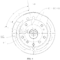
- the projections of the first exhaust hole 4514 and the second exhaust hole 4524 coincide; the intersection point of the center axis of the crankshaft 41 and the datum plane is considered as the origin, so that the angle A, defined between the connection line from the midpoint of the projection of the first exhaust hole 4514 (or the second exhaust hole 4524) on the datum plane to the origin, and the connection line from the end point of the projection of the first gas injection hole 441 on the datum plane to the origin, can represent the angle of the first gas injection hole 441 with respect to the first exhaust hole 4514 (or the second exhaust hole 4524); the angle B, defined between the connection line from the midpoint of the projection of the first exhaust hole 4514 (or the second exhaust hole 4524) on the datum plane to the origin, and the connection line from the end point of the projection of the second gas injection hole 442 on the datum plane to the origin, can represent the angle of the second gas injection
- the angle B is smaller than the angle A, so it can be construed as that the second injection port 442 is located at the side of the first gas injection hole 441 adjacent to the first exhaust hole 4514 (or the second exhaust hole 4524) in the rolling direction of the piston.
- the present disclosure is not limited thereby - as shown in Fig. 5 , the first gas injection hole 441 and the second gas injection hole 442 can also be formed in the main bearing 421 and the auxiliary bearing 422 respectively. That is, the first gas injection hole 441 is formed in the main bearing 421, and the second gas injection hole 442 is formed in the auxiliary bearing 422.
- the first gas injection hole 441 and the second gas injection hole 442 can be periodically opened and closed following the rolling of the first piston 461 and the second piston 462 respectively.
- the second gas injection hole 442 is located at the side of the first gas injection hole 441 adjacent to the exhaust hole in the rolling direction of the piston.
- the second gas injection hole 442 is closer to the exhaust hole with respect to the first gas injection hole 441 in the rotating direction of the compressor. Therefrom, it is convenient to process and realize the control over the opening and closing of the first gas injection hole 441 and the second gas injection hole 442.
- the tail portion of the sliding vane of the said another cylinder i.e. the cylinder provided with the sliding vane optionally in contact with or separate from the corresponding piston
- the sliding braking device 482 when the pressure difference between the tail portion of the sliding vane and the head portion the sliding vane is larger than braking force acted on the sliding vane by the sliding vane braking device 482, the sliding vane is separated from the sliding vane braking device 482, and the head portion of the sliding vane is pressed against to the outer circumferential wall of the corresponding piston.
- the braking force is from 2N to 10N.
- the sliding braking device 482 can be a magnet, fixed in the second cylinder 452, and located between the rear end of the second sliding vane 472 and the inner side wall of the housing 2; the second sliding vane 472 slides in the second sliding vane groove 4522 due to the pressure difference between the rear end and the front end thereof.
- the second sliding vane 472 can slide inwards to the second compression chamber 4521 to be separate from the sliding braking device 482, and the front end of the second sliding vane 472 abuts against the outer circumferential wall of the second piston 462 (as shown in Fig. 2 ).
- the sliding vane 472 When the pressure difference between the rear end and front end of the second sliding vane 472 is smaller than or equal to the braking force, the sliding vane 472 is appressed with the sliding vane braking device 482 to keep relatively static with respect to the sliding vane braking device 482, so as to be separate from the outer circumferential wall of the second piston 462 (as shown in Fig. 3 ).
- the refrigeration cycle device 1000 includes: the rotary compressor 700 according to embodiments of the first aspect of the present disclosure, a second direction control assembly 100 (for example a four-way reversing valve), an outdoor heat exchanger 200, an indoor heat exchanger 300, and a flash tank 400.
- a second direction control assembly 100 for example a four-way reversing valve
- the flash tank 400 can have a gas-liquid separation function which is generally well known by those skilled in the art and consequently will not be described in detail herein.
- the second direction control assembly 100 includes a first connector 101 connected to the exhaust hole 21 of the rotary compressor 700, a second connector 102, a third connector 103, and a fourth connector 104 connected to the liquid reservoir 1; a first end of the outdoor heat exchanger 200 is connected to the second connector 102, while a first end of the indoor exchanger 300 is connected to the third connector 103; a second end of the indoor exchanger 300 is connected to a second end of the outdoor exchanger 200; the flash tank 400 is connected between the second end of the indoor exchanger 300 and the second end of the outdoor exchanger 200, and connected to the first gas injection hole 441 and the second gas injection hole 442; in addition, a first throttling element 500 can be connected between the outdoor heat exchanger 200 and the flash tank 400, and a second throttling element 600 can be connected between the indoor heat exchanger 300 and the flash tank 400.
- Fig. 7 illustrates the refrigerant flow direction when the refrigeration cycle device 1000 works in a certain working mode.
- the refrigeration cycle device 1000 has the higher operating efficiency and wider application range, by providing the rotary compressor 700 according to embodiments of the first aspect of the present disclosure.
- first and second are used herein for purposes of description and are not intended to indicate or imply relative importance or significance or to imply the number of indicated technical features.
- the feature defined with “first” and “second” may comprise one or more of this feature.
- a plurality of' means two or more than two, unless specified otherwise.
- the terms “mounted,” “connected,” “coupled,” “fixed” and the like are used broadly, and may be, for example, fixed connections, detachable connections, or integral connections; may also be mechanical or electrical connections; may also be direct connections or indirect connections via intervening structures; may also be inner communications of two elements, which can be understood by those skilled in the art according to specific situations.
- a structure in which a first feature is "on" or “below” a second feature may include an embodiment in which the first feature is in direct contact with the second feature, and may also include an embodiment in which the first feature and the second feature are not in direct contact with each other, but are contacted via an additional feature formed therebetween.
- a first feature "on,” “above,” or “on top of' a second feature may include an embodiment in which the first feature is right or obliquely “on,” “above,” or “on top of' the second feature, or just means that the first feature is at a height higher than that of the second feature; while a first feature "below,” “under,” or “on bottom of' a second feature may include an embodiment in which the first feature is right or obliquely “below,” “under,” or “on bottom of' the second feature, or just means that the first feature is at a height lower than that of the second feature.
Landscapes
- Engineering & Computer Science (AREA)
- Mechanical Engineering (AREA)
- General Engineering & Computer Science (AREA)
- Physics & Mathematics (AREA)
- Fluid Mechanics (AREA)
- Applications Or Details Of Rotary Compressors (AREA)
Abstract
Description
- The present disclosure relates to a compressor device, and more particularly to a rotary compressor and a refrigeration cycle device having the same.
- The related technologies indicate that in some applications, for example, in heat pump application in low temperature environment, the decrease of the evaporating temperature will lead to the reduce of the capacity of a refrigeration cycle system, and the performance of an ordinary single-stage rotary compressor becomes too worse to use. If a solution of large-capacity enhanced vapor injection is adopted, the capacity of the refrigeration cycle system can be improved effectively, but an ordinary high displacement double-cylinder enhanced vapor injection rotary compressor still performs a double-cylinder operation in case of a small compression load, which makes the running efficiency worse.
- Embodiments of the present disclosure seek to solve at least one of the problems existing in the related art to at least some extent. Therefore, the present disclosure aims to provide a rotary compressor that has advantages of a simple and reasonable structure, a high operating efficiency, a wide range of application, and an excellent low temperature heating effect.
- The present disclosure further provides a refrigeration cycle device comprising the above-identified rotary compressor.
- According to a first aspect of the present disclosure, the rotary compressor comprises: a liquid reservoir; a housing disposed outside the liquid reservoir, in which an exhaust hole is formed; a compression mechanism disposed within the housing; and a first direction control assembly comprising a first valve port connected to said another cylinder, a second valve port connected to the liquid reservoir, and a third valve port in communication with the exhaust hole, one of the second valve port and the third port being in communication with the first valve port. The compression mechanism comprises a main bearing, a cylinder assembly, an auxiliary bearing, two pistons and two sliding vanes, wherein the main bearing and the auxiliary bearing are disposed at both axial ends of the cylinder assembly respectively; the cylinder assembly comprises two cylinders having compression chambers, and a partition plate arranged between the two cylinders, on each of which a sliding vane groove, a gas suction hole and an exhaust hole are formed; each piston is disposed inside the corresponding compression chamber and capable of rolling along an inner wall of the compression chamber; each sliding vane is movably disposed inside the corresponding sliding vane groove, a head portion of the sliding vane of one of the two cylinders abutting against an outer circumferential wall of the corresponding piston, while the sliding vane of the other one of the two cylinders being optionally in contact with or separate from the corresponding piston. The compressor mechanism is provided with a first gas injection hole for injecting a refrigerant into the compression chamber of the one of the cylinder, and a second gas injection hole for unidirectionally injecting the refrigerant into the compression chamber of another cylinder.
- The rotary compressor according to the present disclosure has the advantages of the high operating efficiency, wide application range, and excellent low temperature heating effect.
- In addition, the rotary compressor according to the above embodiment of the present disclosure can also have the additional technological features.
- According to an embodiment of the present disclosure, the first gas injection hole and the second gas injection hole are formed in the partition plate.
- According to an embodiment of the present disclosure, the first gas injection hole and the second gas injection hole are formed in the main bearing and the auxiliary bearing respectively.
- According to an embodiment of the present disclosure, the second gas injection hole is located at a side of the first gas injection hole adjacent to the exhaust hole in the rolling direction of the piston.
- According to an embodiment of the present disclosure, the rotary compressor further comprises a one-way valve, disposed at the second gas injection hole and configured to unidirectionally inject the refrigerant into the compression chamber of said another cylinder.
- According to an embodiment of the present disclosure, a tail portion of the sliding vane of the said another cylinder is provided with a sliding braking device; when the pressure difference between the tail portion of the sliding vane and the head portion of the sliding vane is greater than a braking force acted on the sliding vane by the sliding vane braking device, the sliding vane is separated from the sliding vane braking device, and the head portion of the sliding vane is pressed against the outer circumferential wall of the corresponding piston.
- According to an embodiment of the present disclosure, the braking force is from 2N to 10N.
- According to an embodiment of the present disclosure, the third valve port is directly connected to the exhaust hole or an interior of the housing.
- According to an embodiment of the present disclosure, the first direction control assembly is a three-way valve.
- According to a second aspect of the present disclosure, the refrigeration cycle device comprises the rotary compressor according to embodiments of the first aspect of the present disclosure; a second direction control assembly comprising a first connector, a second connector, a third connector and a fourth connector, the first connector being connected to the exhaust hole of the rotary compressor and the fourth connector being connected to the liquid reservoir; an outdoor heat exchanger having a first end connected to the second connector; an indoor heat exchanger having a first end connected to the third connector and a second end connected to a second end of the outdoor exchanger; and a flash tank connected between the second end of the indoor exchanger and the second end of the outdoor exchanger, wherein the flash tank is connected to the first gas injection hole and the second gas injection hole of the rotary compressor.
- For the refrigeration cycle device according to the present disclosure, by providing the rotary compressor according to embodiment of the first aspect of the present disclosure, the overall performance of the refrigeration cycle device may be improved.
- Additional aspects and advantages of embodiments of present disclosure will be given in part in the following descriptions, become apparent in part from the following descriptions, or be learned from the practice of embodiments of the present disclosure.
-
-
Fig. 1 shows a sectional view of a rotary compressor from one perspective according to an embodiment of the present disclosure. -
Fig. 2 shows a sectional view of the rotary compressor ofFig.1 from another perspective, wherein a first valve port of a first direction control assembly is in communication with a second valve port thereof. -
Fig. 3 shows a sectional view of the rotary compressor ofFig.1 from another perspective, wherein the first valve port of the first direction control assembly is in communication with a third valve port thereof. -
Fig. 4 shows a sectional view taken along line D-D ofFig. 2 . -
Fig. 5 shows a sectional view of a rotary compressor according to another embodiment of the present disclosure. -
Fig. 6 shows a sectional view of a rotary compressor according to another embodiment of the present disclosure. -
Fig. 7 shows schematic view of a system structure of a refrigeration cycle device according to an embodiment of the present disclosure. - 1000: refrigeration cycle device
- 100: second direction control assembly;
- 101: first connector; 102: second connector;
- 103: third connector; 104: fourth connector;
- 200: outdoor heat exchanger;
- 300: indoor heat exchanger;
- 400: flash tank;
- 500: first throttling member;
- 600: second throttling member;
- 700: rotary compressor;
- 1: liquid reservoir;
- 11: first gas suction pipe; 12: second gas suction pipe;
- 2: housing: 21: exhaust hole; 22: exhaust pipe; 3: motor;
- 41: crankshaft; 421: main bearing; 4211: first exhaust valve;
- 422: auxiliary bearing; 4221: second exhaust valve;
- 431: first muffler; 432: second muffler;
- 44: gas injection pipe; 441: first gas injection hole; 442: second gas injection hole; 443: one-way valve;
- 451: first cylinder; 4511: first compression chamber; 4512: first sliding vane groove; 4513: first gas suction hole; 4514: first exhaust hole;
- 452: second cylinder; 4521: second compression chamber; 4522: second sliding vane groove; 4523: second gas suction hole; 4524: second exhaust hole;
- 453: partition plate; 4531: first partition plate; 4532: second partition plate;
- 461: first piston; 462: second piston;
- 471: first sliding vane; 472: second sliding vane;
- 481: spring; 482: sliding vane braking device;
- 49: first direction control assembly; 491: first valve port; 492: second valve port; 493: third valve port.
- Embodiments of the present invention will be described in detail and examples of the embodiments will be illustrated in the drawings, in which same or similar reference numerals are used to indicate same or similar members or members with same or similar functions throughout the specification. The embodiments described herein with reference to drawings are explanatory, which are used to illustrate the present invention, but shall not be construed to limit the present disclosure.
- Various embodiments and examples are provided in the following description to implement different structures of the present disclosure. In order to simplify the present disclosure, certain elements and settings will be described. However, these elements and settings are only by way of example and are not intended to limit the present disclosure. In addition, reference numerals and/or letters may be repeated in different examples in the present disclosure. This repeating is for the purpose of simplification and clarity and does not refer to relations between different embodiments and/or settings. Furthermore, examples of different processes and materials are provided in the present disclosure. However, it would be appreciated by those skilled in the art that other processes and/or materials may be also applied.
- A
rotary compressor 700 according to embodiments of the first aspect of the present disclosure will be described below with reference toFigs. 1-6 . - As shown in
Fig. 1 , therotary compressor 700 includes: aliquid reservoir 1, a housing 2, a compression mechanism, and a firstdirection control assembly 49. - Specifically, the housing 2 is disposed outside the
liquid reservoir 1 and formed with anexhaust hole 21 therein. According toFig. 1 , therotary compressor 700 can be a vertical compressor, and hereby, the housing 2 can be substantially formed as a hollow and sealed cylindrical tube shape, with a central axis thereof extending in the vertical direction; theexhaust hole 21 can penetrate a top wall of the housing 2 in an up-and-down direction, and an vertically extendedexhaust pipe 22 can be inserted into theexhaust hole 21 to discharge a gaseous refrigerant (or a mixture with part of liquid refrigerant and lubricating oil) from the interior of the housing 2; theliquid reservoir 1 is disposed outside the housing 2. Of course, the present invention is not limited thereto, i.e. therotary compressor 700 can be a horizontal compressor, and hereby, the central axis of the housing 2 can extend in the horizontal direction. Only therotary compressor 700 configured as the vertical compressor will be exemplified below. - Specifically, the compression mechanism is disposed within the housing 2, and includes a cylinder assembly, a
main bearing 421 and anauxiliary bearing 422 disposed separately at both axial ends of the cylinder assembly. For example, as shown inFig. 1 , themain bearing 421 is disposed at the top of the cylinder assembly, while theauxiliary bearing 422 is disposed at the bottom of the cylinder assembly. - Further, the cylinder assembly comprises two cylinders provided with compression chambers, and a
partition plate 453 arranged between the two cylinders. That is, the cylinder assembly includes two cylinders, thepartition plate 453 is arranged between the two cylinders, and each of the two cylinders has a compression chamber. As shown inFigs. 1 and2 , the cylinder assembly includes afirst cylinder 451 disposed above thepartition plate 453 and asecond cylinder 452 disposed below thepartition 453; themain bearing 421, thefirst cylinder 451, and thepartition plate 453 define afirst compression chamber 4511, while thepartition plate 453, thesecond cylinder 452 and theauxiliary bearing 422 define asecond compression chamber 4521. - Further, the compression mechanism also includes two pistons and two sliding vanes, each piston is disposed inside the corresponding compression chamber and capable of rolling along an inner wall of the compression chamber, and each sliding vane is movably disposed inside the corresponding sliding vane groove. A sliding vane groove, a gas suction hole and an exhaust hole are formed on each cylinder, in which the exhaust hole is directly or indirectly connected to the interior of the housing 2, and thereby connected to the
exhaust hole 21. - As shown in
Figs. 1 and2 , the two sliding vanes are represented by a first slidingvane 471 and asecond vane 472, and the two pistons are represented by afirst piston 461 and asecond piston 462; a first slidingvane groove 4512, a firstgas suction hole 4513 and afirst exhaust hole 4514 are formed on thefirst cylinder 451; thefirst piston 461 is disposed inside thefirst compression chamber 4511 and rolls along the inner wall of thefirst compression chamber 4511; the first slidingvane groove 4512 can extend in a radial direction of thefirst cylinder 451, and the first slidingvane 471 is movably disposed inside the first slidingvane groove 4512 along a length direction thereof; a second slidingvane groove 4522, a secondgas suction hole 4523 and asecond exhaust hole 4524 are formed on thesecond cylinder 452; thesecond piston 462 is disposed inside thesecond compression chamber 4521 and rolls along the inner wall of thesecond compression chamber 4521; the second slidingvane groove 4522 can extend in a radial of thesecond cylinder 452, and the second slidingvane 472 is movably disposed inside the second slidingvane groove 4522 along a length direction thereof. - The head portion of the sliding vane of one of the two cylinders abuts against an outer circumferential wall of the corresponding piston, while the sliding vane of the other one of the two cylinders can be optionally in contact with or separate from the corresponding piston. That is, there are two possibilities: first, when the head portion of the first sliding
vane 471 of thefirst cylinder 451 abuts against the outer circumferential wall of thefirst piston 461, the slidingvane 472 of thesecond cylinders 452 can optionally contact or separate from thesecond piston 462; second, when the head portion of the second slidingvane 472 of thesecond cylinder 452 abuts against the outer circumferential wall of thesecond piston 462, the slidingvane 471 of thefirst cylinders 451 can optionally contact or separate from thefirst piston 461. Only the first possibility is exemplified below. Of course, those skilled in the art may apparently appreciate the second possible technical solution after reading the first possible technical solution below. Herein, it should be noted that the head portion of the sliding vane can be construed as an end of the sliding vane adjacent to the central axis of the corresponding compression chamber, and the opposite end thereof is the tail portion of the sliding vane which away from the central axis of the corresponding compression chamber. - Optionally, referring to
Fig. 2 , aspring 481 may be provided between the tail portion of the first slidingvane 471 and inner side wall of the housing 2, and keep pushing the head portion of the first slidingvane 471 to abut against to the outer circumferential wall of thefirst piston 461; abraking device 482 may be provided between the tail portion of the second slidingvane 472 and the inner side wall of the housing 2, and control the head portion of the second slidingvane 472 to abut against the outer circumferential wall of thesecond piston 462 under some working conditions and control the head portion of the second slidingvane 472 to separate from the outer circumferential wall of thesecond piston 462 under other working conditions. Herein, it should be noted that the devices capable of controlling the first slidingvane 471 and the second slidingvane 472 are not limited to thespring 481 and the slidingbraking device 482. Additionally, it shall be noted that the slidingbraking device 482 will be described in detail below, and thus will not be described herein. - On the compression mechanism, a first
gas injection hole 441 is formed and configured to inject the refrigerant into the compression chamber of one of the cylinders (i.e. the cylinder provided with the sliding vane with its head portion abutting against the outer circumferential wall of the piston), and a secondgas injection hole 442 is formed and configured to unidirectionally inject the refrigerant into the compression chamber of the other cylinder (i.e. the cylinder provided with the sliding vane optionally in contact with or separate from the corresponding piston). As shown inFig. 2 , the compression mechanism is provided with the firstgas injection hole 441 for injecting the refrigerant into thefirst compression chamber 4511 of thefirst cylinder 451, and thesecond injection hole 442 for unidirectionally injecting the refrigerant into thesecond compression chamber 4512 of thesecond cylinder 452. Herein, the term "injecting unidirectionally" can be construed as that the refrigerant in thesecond compression chamber 4521 will not flow back to the secondgas injection hole 442. In addition, it should be noted that the specific position of the specific configurations of the firstgas injection hole 441 and the secondgas injection hole 442 will be described in detail below, and thus will not be described herein. - Optionally, a one-
way valve 443 may be provided to realize a check function. That is, therotary compressor 700 further includes the one-way valve 443 disposed at the secondgas injection hole 442 and configured to unidirectionally inject the refrigerant into the compression chamber of said another cylinder (i.e. the cylinder provided with the sliding vane optionally in contact with or separate from the corresponding piston). As shown inFig. 2 , the one-way valve 443 is disposed at the secondgas injection hole 442 and configured to unidirectionally inject the refrigerant into thesecond compression chamber 4521 of thesecond cylinder 452, so as to prevent the refrigerant in thesecond compression chamber 4521 from flowing back to the secondgas injection hole 442. Of course, the present disclosure is not limited thereby - other devices may be provided to realize the anti-backflow function. - Further, referring to
Fig. 2 and3 , the firstdirection control assembly 49 includes afirst valve port 491 connected to said another cylinder (i.e. the cylinder provided with the sliding vane optionally in contact with or separate from the corresponding piston), asecond valve port 492 connected to theliquid reservoir 1, and athird valve port 493 in communication with the exhaust hole (i.e. thefirst exhaust hole 4514 or the second exhaust hole 4524), in which one of thesecond valve port 492 and thethird port 493 is optionally in communication with thefirst valve port 491. That is, thesecond valve port 492 is in communication with thefirst valve port 491 under some working conditions (as shown inFig. 2 ), while thethird port 493 is in communication with thefirst valve port 491 under other working conditions (as shown inFig. 3 ). Optionally, the firstdirection control assembly 49 is a three-way valve. Of course, the present disclosure is not limtited thereby - the firstdirection control assembly 49 can also be configured as other structures capable of achieving the three-way switching effect. - Herein, it should be noted that the
third valve port 493 is in communication with the exhaust hole, and then may be in communication with the interior of the housing 2 and theexhaust hole 21 since the exhaust hole is in communication with the interior of the housing 2 and theexhaust hole 21. That is, thethird valve port 493 can direct the exhaust pressure out of theexhaust pipe 22 or the sealed housing 2. As shown inFigs. 1 to 3 , thethird valve port 493 is connected to theexhaust hole 21, so as to be in communication with the exhaust hole. Alternatively, as shown inFig. 6 , thethird valve port 493 is connected to the interior of the housing 2, so as to be in communication with the exhaust hole. Therefrom, it is convenient to process and implement. - As shown in
Figs. 1 to 3 , thefirst gas suction 4513 of thefirst cylinder 451 is connected to and in communication with theliquid reservoir 1; the secondgas suction hole 4523 of thesecond cylinder 452 is connected to and in communication with thefirst valve port 491 of the firstdirection control assembly 49; thefirst exhaust hole 4514 of thefirst cylinder 451 is directly in communication with the interior of the housing 2, or indirectly in communication with that by afirst muffler 431 described below, and thesecond exhaust hole 4524 of thesecond cylinder 452 is directly in communication with the interior of the housing 2, or indirectly in communication with that by asecond muffler 432 described below, so that thefirst exhaust hole 4514 and thesecond exhaust hole 4524 can be in communication with theexhaust hole 21 via the interior of the housing 2. - Referring to
Fig. 2 , thesecond valve port 492 of the firstdirection control assembly 49 is connected and communicated with theliquid reservoir 1, and when thesecond valve port 492 is in communication with thefirst valve port 491, theliquid reservoir 1 can deliver the refrigerant to thesecond compression chamber 4521 through the secondgas suction hole 4523. Referring toFig. 3 , thethird valve port 493 of the firstdirection control assembly 49 is in communication with thefirst exhaust hole 4514 or thesecond exhaust hole 4524. That is, thethird valve port 493 of the firstdirection control assembly 49 is in communication with the interior of the housing 2 and theexhaust hole 21, so that when thethird valve port 493 is in communication with thefirst valve port 491, the secondgas suction hole 4523 is in communication with the interior of the housing 2 and theexhaust hole 21. - Thus, in the working process of the
rotary compressor 700, two working modes can be achieved by switching between the two communication modes via the firstdirection control assembly 49, namely, a full load working mode and a part load working mode. - Specially, as shown in
Figs. 1 and2 , when therotary compressor 700 adopts the full load working mode, the firstdirection control assembly 49 is configured to communicate thefirst valve port 491 with thesecond valve port 492, to communicate the secondgas suction hole 4523 of thesecond cylinder 452 with theliquid reservoir 1. Hereby, the low-pressure refrigerant with pressure Ps at the evaporation side of the refrigeration cycle device 1000 (which will be described hereinafter) flows through theliquid reservoir 1, into thefirst cylinder 451 via the firstgas suction hole 4513, and meanwhile, flows through the firstdirection control assembly 49 and the second gas suction hole 45223, into thesecond cylinder 452, in which case thefirst cylinder 451 and thesecond cylinder 452 both work normally. The low-pressure refrigerant, flows into the interior of the sealed housing 2 respectively through thefirst exhaust hole 4514 and thesecond exhaust hole 4524, and is discharged from theexhaust pipe 22 at theexhaust hole 21, after being compressed by thefirst cylinder 451 and thesecond cylinder 452 respectively, with the pressure increased to Pd, in which case therotary compressor 700 is running in a double-cylinder manner and works in the full load working mode. - In the full load working mode, since the pressure at the second
gas suction hole 4523 is the low pressure Ps and the back pressure at the tail portion of the second slidingvane 472 is the high pressure Pd inside the sealed housing 2, the second slidingvane 472 is departed from the sliding braking device 482 (as shown inFig. 2 ) under the action of the pressure difference, and the head portion of the second slidingvane 472 moves in contact with the outer circumferential wall of thesecond piston 462, so that thesecond cylinder 452 may work normally, in which case the enhanced vapor refrigerant with pressure Pm from therefrigeration cycle device 1000 may be injected into thefirst compression chamber 4511 via thefirst injection port 441, and meanwhile be unidirectionally injected into thesecond compression chamber 4521 via thesecond injection port 442, so as to achieve the double-cylinder injection operation of therotary compressor 700. - Specially, as shown in
Figs. 1 and3 , when therotary compressor 700 adopts the part load working mode, the firstdirection control assembly 49 is configured to communicate thefirst valve port 491 with thethird valve port 493, so as to communicate the secondgas suction hole 4523 of thesecond cylinder 452 with the interior of the housing 2 and theexhaust hole 21. Hereby, the low pressure refrigerant with pressure Ps from the evaporation side of therefrigeration cycle device 1000 enters thefirst cylinder 451 only via the firstgas suction hole 4513 after flowing through theliquid reservoir 1, and then thefirst cylinder 451 works normally. Since the secondgas suction hole 4523 is in communication with the interior of the housing 2 and theexhaust hole 21, the interior of thesecond compression chamber 4521 has a high-pressure refrigerant, the pressure of the secondgas suction hole 4523 is the high pressure Pd, and meanwhile the back pressure at the tail portion of the second slidingvane 472 is the high pressure Pd inside the sealed housing 2, so that the slidingvane 472 is stopped in the second sliding vane groove 4522 (as shown inFig. 3 ) under the action of the slidingvane braking device 482, due to the lack of enough pressure difference, and the head portion of the second slidingvane 472 is departed from the outer circumferential wall of thesecond piston 462, and thus thesecond cylinder 452 stops working, in which case the rotary compressor works in the part load working mode. - In the part load working mode, the enhanced vapor refrigerant with pressure Pm from the
refrigeration cycle device 1000 is injected into thefirst compression chamber 4511 via thefirst injection port 441, and meanwhile, the high-pressure refrigerant with pressure Pd of the interior of the second compression chamber is stopped by the one-way valve 443 and thus cannot flow to the secondgas injection hole 442, so as to achieve the single-cylinder injection operation of therotary compressor 700. - The
rotary compressor 700 according to embodiments of the present disclosure, can be the variable displacement enhanced vapor injection compressor, and can switch readily between the full load working mode and the part load working mode by providing the firstdirection control assembly 49 capable of switching between the two communication modes. Specially, therotary compressor 700 can adopt the part load working mode when the load of the system is small, to make the system operate effectively, and when running in the full load working mode, the capacity of gas delivery of therotary compressor 700 can be increased, so as to improve the heating effect in the low temperature heating application greatly. Thus therotary compressor 700 can have a more reasonable structure, a higher operating efficiency, a wider range of applications, and a more excellent low temperature heating effect. - Hereinafter, the
rotary compressor 700 according to some embodiments of the present disclosure is to be illustrated referring theFigs. 1 to 6 . - Referring to
Figs. 1 and2 , therotary compressor 700 can includes a housing 2, anelectric motor 3 and a compression mechanism disposed in the housing 2; theelectric motor 3 is connected to the compression mechanism that includes afirst cylinder 451 on the top of which amain bearing 421 is disposed, asecond cylinder 452 at the bottom of which anauxiliary bearing 422 is disposed, and apartition plate 453 which can consist of afirst partition plate 4531 and a second partition plate 4532. - Referring to
Figs. 1 and2 , thefirst cylinder 451 is formed with afirst compression chamber 4511, and provided with a first piston 461 (rolling piston) rotating eccentrically in thefirst compression chamber 4511 of thefirst cylinder 451, and a first slidingvane 471 received in the first slidingvane groove 4512 and having a head portion (front end) in contact with the outer circumferential wall of thefirst piston 461 and a tail portion (rear end) provided with aspring 481. - Referring to
Figs. 1 and2 , thesecond cylinder 452 is formed asecond compression chamber 4521, and provided with a second piston 462 (rolling piston) rotating eccentrically in thesecond compression chamber 4521 of thesecond cylinder 452, and a second slidingvane 472 received in the second slidingvane groove 4522 and having a head portion (front end) optionally in contact with or separate from the outer circumferential wall of thesecond piston 462 and a tail portion (rear end) provided with aspring 482. - Referring to
Figs. 1 and2 , the compression mechanism also includes acrankshaft 41 over which thefirst piston 461 and thesecond piston 462 are both fitted, so as to actuate thefirst piston 461 and thesecond piston 462 to roll at same time in the corresponding compression chambers by thecrankshaft 41. - Referring to
Figs. 1 and2 , thefirst cylinder 451 is formed with a firstgas suction hole 4513 and afirst exhaust hole 4514, and also provided with the a firstgas suction pipe 11, one end of the firstgas suction pipe 11 being connected to the firstgas suction hole 4513, and the other end thereof being connected to theliquid reservoir 1; thefirst exhaust hole 4514 is in communication with the interior of the housing 2 via thefirst exhaust valve 4211 of themain bearing 421 and thefirst muffler 431. - Referring to
Figs. 1 and2 , thesecond cylinder 452 is formed with a secondgas suction hole 4523 and asecond exhaust hole 4524, and also provided with a secondgas suction pipe 12, one end of the secondgas suction pipe 12 being connected to the secondgas suction hole 4523, and the other end being optionally in communication with theliquid reservoir 1 and the exhaust hole 21 (or the interior of the housing 2) via the direction control assembly 49 (for example a three-way valve); thesecond exhaust hole 4524 is in communication with the interior of the housing 2 via the second exhaust valve of theauxiliary bearing 422 and thesecond muffler 432. - Further, the
partition plate 453 is formed with a firstgas injection hole 441 in communication with thefirst compression chamber 4511, and a secondgas injection hole 442 in communication with thesecond compression chamber 4521. That is, the firstgas injection hole 441 and the secondgas injection hole 442 can be formed in thepartition plate 453. Hereby, as shown inFig. 2 , therotary compressor 700 can also include thegas injection pipe 44; the firstgas injection hole 441 and the secondgas injection hole 442 are separately connected to thegas injection pipe 44, in which the one-way valve 443 is disposed between the secondgas injection hole 442 and thegas injection pipe 44 and then gas can flow unidirectionally from thegas injection pipe 44 to the secondgas injection hole 442 via the one-way valve 443, such that the firstgas injection hole 441 and the secondgas injection hole 442 can be periodically opened and closed following the rolling of thefirst piston 461 and thesecond piston 462 respectively. Therefrom, it is intended to facilitate the machining and the control over the opening and closing of the firstgas injection hole 441 and the secondgas injection hole 442. - Since in the two working modes of the
rotary compressor 700, thefirst cylinder 451 is always in the working state, that is, thefirst cylinder 451 is required to work when the load is small. When the load of therotary compressor 700 is small, the injection termination time is earlier, the firstgas injection hole 441 shall be closed earlier, but when thesecond cylinder 452 works at high load, the secondgas injection hole 442 shall be closed later to increase the injection quantity. Therefrom, as shown inFig. 4 , the secondgas injection hole 442 should be located at the side of the firstgas injection hole 441 adjacent to the corresponding exhaust hole in the rolling direction of the piston (since the projection of thefirst exhaust hole 4514 and that of thesecond exhaust hole 4524 on a datum plane mentioned hereinafter coincide, it is reasonable to interpret the exhaust hole herein as either of thefirst exhaust hole 4514 and the second exhaust hole 4524). In other words, the secondgas injection hole 442 is closer to the exhaust hole in the compressor rotating direction compared with the firstgas injection hole 441. Therefrom, therotary compressor 700 can switch better and more effectively between the two working modes of the full load working mode and the part load working mode, and can have the more reasonable structure, higher operating efficiency, wider application range, and more excellent low temperature heating effect. - As shown in
Fig. 4 , on the datum plane perpendicular to the center axis of thecrankshaft 41, the projections of thefirst exhaust hole 4514 and thesecond exhaust hole 4524 coincide; the intersection point of the center axis of thecrankshaft 41 and the datum plane is considered as the origin, so that the angle A, defined between the connection line from the midpoint of the projection of the first exhaust hole 4514 (or the second exhaust hole 4524) on the datum plane to the origin, and the connection line from the end point of the projection of the firstgas injection hole 441 on the datum plane to the origin, can represent the angle of the firstgas injection hole 441 with respect to the first exhaust hole 4514 (or the second exhaust hole 4524); the angle B, defined between the connection line from the midpoint of the projection of the first exhaust hole 4514 (or the second exhaust hole 4524) on the datum plane to the origin, and the connection line from the end point of the projection of the secondgas injection hole 442 on the datum plane to the origin, can represent the angle of the secondgas injection hole 442 with respect to the first exhaust hole 4514 (or the second exhaust hole 4524). The angle B is smaller than the angle A, so it can be construed as that thesecond injection port 442 is located at the side of the firstgas injection hole 441 adjacent to the first exhaust hole 4514 (or the second exhaust hole 4524) in the rolling direction of the piston. - Of course, the present disclosure is not limited thereby - as shown in
Fig. 5 , the firstgas injection hole 441 and the secondgas injection hole 442 can also be formed in themain bearing 421 and theauxiliary bearing 422 respectively. That is, the firstgas injection hole 441 is formed in themain bearing 421, and the secondgas injection hole 442 is formed in theauxiliary bearing 422. Hereby, the firstgas injection hole 441 and the secondgas injection hole 442 can be periodically opened and closed following the rolling of thefirst piston 461 and thesecond piston 462 respectively. Similarly, as shown inFig. 4 , the secondgas injection hole 442 is located at the side of the firstgas injection hole 441 adjacent to the exhaust hole in the rolling direction of the piston. That is, the secondgas injection hole 442 is closer to the exhaust hole with respect to the firstgas injection hole 441 in the rotating direction of the compressor. Therefrom, it is convenient to process and realize the control over the opening and closing of the firstgas injection hole 441 and the secondgas injection hole 442. - In an alternative embodiment of the present disclosure, the tail portion of the sliding vane of the said another cylinder (i.e. the cylinder provided with the sliding vane optionally in contact with or separate from the corresponding piston) is provided with the sliding
braking device 482; when the pressure difference between the tail portion of the sliding vane and the head portion the sliding vane is larger than braking force acted on the sliding vane by the slidingvane braking device 482, the sliding vane is separated from the slidingvane braking device 482, and the head portion of the sliding vane is pressed against to the outer circumferential wall of the corresponding piston. Optionally, the braking force is from 2N to 10N. Therefrom, it is ensured that therotary compressor 700 can reliably switch between the two working modes of the full load working mode and the part load working mode. - As shown in
Figs. 2 andFig. 3 , the slidingbraking device 482 can be a magnet, fixed in thesecond cylinder 452, and located between the rear end of the second slidingvane 472 and the inner side wall of the housing 2; the second slidingvane 472 slides in the second slidingvane groove 4522 due to the pressure difference between the rear end and the front end thereof. When the pressure difference between the rear end and front end of the second slidingvane 472 is greater than the braking force, the second slidingvane 472 can slide inwards to thesecond compression chamber 4521 to be separate from the slidingbraking device 482, and the front end of the second slidingvane 472 abuts against the outer circumferential wall of the second piston 462 (as shown inFig. 2 ). When the pressure difference between the rear end and front end of the second slidingvane 472 is smaller than or equal to the braking force, the slidingvane 472 is appressed with the slidingvane braking device 482 to keep relatively static with respect to the slidingvane braking device 482, so as to be separate from the outer circumferential wall of the second piston 462 (as shown inFig. 3 ). - The
refrigeration cycle device 1000 according to embodiments of the second aspect of the present disclosure, includes: therotary compressor 700 according to embodiments of the first aspect of the present disclosure, a second direction control assembly 100 (for example a four-way reversing valve), anoutdoor heat exchanger 200, anindoor heat exchanger 300, and aflash tank 400. Herein, it should be noted that theflash tank 400 can have a gas-liquid separation function which is generally well known by those skilled in the art and consequently will not be described in detail herein. - Specially, as shown in
Fig. 7 , the seconddirection control assembly 100 includes afirst connector 101 connected to theexhaust hole 21 of therotary compressor 700, asecond connector 102, athird connector 103, and afourth connector 104 connected to theliquid reservoir 1; a first end of theoutdoor heat exchanger 200 is connected to thesecond connector 102, while a first end of theindoor exchanger 300 is connected to thethird connector 103; a second end of theindoor exchanger 300 is connected to a second end of theoutdoor exchanger 200; theflash tank 400 is connected between the second end of theindoor exchanger 300 and the second end of theoutdoor exchanger 200, and connected to the firstgas injection hole 441 and the secondgas injection hole 442; in addition, afirst throttling element 500 can be connected between theoutdoor heat exchanger 200 and theflash tank 400, and asecond throttling element 600 can be connected between theindoor heat exchanger 300 and theflash tank 400. Therefrom, it is possible to achieve the circulation of the refrigerant and enable therefrigeration cycle device 1000 to perform the refrigerating and heating work. The work principle of therefrigeration cycle device 1000 should be generally well known by those skilled in the art and thus will not be described in detail herein. In addition, the arrow direction inFig. 7 illustrates the refrigerant flow direction when therefrigeration cycle device 1000 works in a certain working mode. - The
refrigeration cycle device 1000 according to embodiments of the present disclosure has the higher operating efficiency and wider application range, by providing therotary compressor 700 according to embodiments of the first aspect of the present disclosure. - In the specification, it is to be understood that terms such as "central," "upper," "lower," "front," "rear," "vertical," "horizontal," "top," "bottom," "inner," "outer," "radial," and "circumferential" should be construed to refer to the orientation as then described or as shown in the drawings under discussion. These relative terms are for convenience and simplification of description of the present disclosure, and do not alone indicate or imply that the device or element referred to must have a particular orientation, and must be constructed or operated in a particular orientation, thus it should not be construed to a limit to the present disclosure.
- In addition, terms such as "first" and "second" are used herein for purposes of description and are not intended to indicate or imply relative importance or significance or to imply the number of indicated technical features. Thus, the feature defined with "first" and "second" may comprise one or more of this feature. In the description of the present invention, "a plurality of' means two or more than two, unless specified otherwise.
- In the present invention, unless specified or limited otherwise, the terms "mounted," "connected," "coupled," "fixed" and the like are used broadly, and may be, for example, fixed connections, detachable connections, or integral connections; may also be mechanical or electrical connections; may also be direct connections or indirect connections via intervening structures; may also be inner communications of two elements, which can be understood by those skilled in the art according to specific situations.
- In the present invention, unless specified or limited otherwise, a structure in which a first feature is "on" or "below" a second feature may include an embodiment in which the first feature is in direct contact with the second feature, and may also include an embodiment in which the first feature and the second feature are not in direct contact with each other, but are contacted via an additional feature formed therebetween. Furthermore, a first feature "on," "above," or "on top of' a second feature may include an embodiment in which the first feature is right or obliquely "on," "above," or "on top of' the second feature, or just means that the first feature is at a height higher than that of the second feature; while a first feature "below," "under," or "on bottom of' a second feature may include an embodiment in which the first feature is right or obliquely "below," "under," or "on bottom of' the second feature, or just means that the first feature is at a height lower than that of the second feature.
- Reference throughout this specification to "an embodiment," "some embodiments," "one embodiment", "another example," "an example," "a specific example," or "some examples," means that a particular feature, structure, material, or characteristic described in connection with the embodiment or example is included in at least one embodiment or example of the present disclosure. Thus, the appearances of the phrases such as "in some embodiments," "in one embodiment", "in an embodiment", "in another example," "in an example," "in a specific example," or "in some examples," in various places throughout this specification are not necessarily referring to the same embodiment or example of the present disclosure. Furthermore, the particular features, structures, materials, or characteristics may be combined in any suitable manner in one or more embodiments or examples.
- Although explanatory embodiments have been shown and described, it would be appreciated by those skilled in the art that the above embodiments cannot be construed to limit the present disclosure, and changes, alternatives, and modifications can be made in the embodiments without departing from spirit, principles and scope of the present disclosure.
Claims (10)
- A rotary compressor comprising:a liquid reservoir;a housing disposed outside the liquid reservoir, in which an exhaust hole is formed;a compression mechanism disposed within the housing, comprisinga cylinder assembly comprising two cylinders provided with compression chambers, and a partition plate arranged between the two cylinders, in each of which a sliding vane groove, a gas suction hole and an exhaust hole are formed,a main bearing and an auxiliary bearing, disposed at both axial ends of the cylinder assembly respectively,two pistons, each being disposed inside the corresponding compression chamber and capable of rolling along an inner wall of the compression chamber, andtwo sliding vanes, each being movably disposed inside the corresponding sliding vane groove, a head portion of the sliding vane of one of the two cylinders abutting against an outer circumferential wall of the corresponding piston, the sliding vane of the other one of the two cylinders being optionally in contact with or separate from the corresponding piston,wherein the compression mechanism is provided with a first gas injection hole for injecting a refrigerant into the compression chamber of one of the two cylinders, and a second gas injection hole for unidirectionally injecting the refrigerant into the compression chamber of the other one of the two cylinders; anda first direction control assembly comprising a first valve port connected to the gas suction hole of the other one of the two cylinders, a second valve port connected to the liquid reservoir, and a third valve port in communication with the exhaust hole,wherein one of the second valve port and the third port is in communication with the first valve port.
- The rotary compressor according to claim 1, wherein the first gas injection hole and the second gas injection hole are formed in the partition plate.
- The rotary compressor according to claim 1, wherein the first gas injection hole and the second gas injection hole are formed in the main bearing and the auxiliary bearing respectively.
- The rotary compressor according to any of claims 1-3, wherein the second gas injection hole is located at a side of the first gas injection hole adjacent to the exhaust hole in the rolling direction of the piston.
- The rotary compressor according to any of claims 1-4, further comprises: a one-way valve, disposed at the second gas injection hole and configured to unidirectionally inject the refrigerant into the compression chamber of said the other cylinder.
- The rotary compressor according to any of claims 1-5, wherein a sliding vane braking device is provided at a tail portion of the sliding vane of the said the other cylinder; when the difference between the pressure at the tail portion of the sliding vane and that at the head portion thereof is larger than a braking force acted on the sliding vane by the sliding vane braking device, the sliding vane is separated from the sliding vane braking device, and the head portion of the sliding vane abuts against the outer circumferential wall of the corresponding piston.
- The rotary compressor according to claim 6, wherein the braking force ranges from 2N to 10N.
- The rotary compressor according to any of claims 1-7, wherein the third valve port is directly connected to the exhaust hole or an interior of the housing.
- The rotary compressor according to any of claims 1-8, wherein the first direction control assembly is a three-way valve.
- A refrigeration cycle device comprising:a rotary compressor according to any of claims 1-9;a second direction control assembly comprising a first connector, a second connector, a third connector and a fourth connector, wherein the first connector is connected to the exhaust hole of the rotary compressor, and the fourth connector is connected to the liquid reservoir;an outdoor heat exchanger having a first end connected to the second connector;an indoor heat exchanger having a first end connected to the third connector and a second end connected to a second end of the outdoor exchanger; anda flash tank connected between the second end of the indoor exchanger and the second end of the outdoor exchanger, wherein the flash tank is connected to the first gas injection hole and the second gas injection hole of the rotary compressor.
Applications Claiming Priority (1)
| Application Number | Priority Date | Filing Date | Title |
|---|---|---|---|
| PCT/CN2015/087931 WO2017031669A1 (en) | 2015-08-24 | 2015-08-24 | Rotary compressor and freezing circulation device having same |
Publications (3)
| Publication Number | Publication Date |
|---|---|
| EP3343040A1 true EP3343040A1 (en) | 2018-07-04 |
| EP3343040A4 EP3343040A4 (en) | 2019-04-10 |
| EP3343040B1 EP3343040B1 (en) | 2022-03-02 |
Family
ID=58099412
Family Applications (1)
| Application Number | Title | Priority Date | Filing Date |
|---|---|---|---|
| EP15901940.5A Active EP3343040B1 (en) | 2015-08-24 | 2015-08-24 | Rotary compressor and freezing circulation device having same |
Country Status (5)
| Country | Link |
|---|---|
| US (1) | US10465682B2 (en) |
| EP (1) | EP3343040B1 (en) |
| JP (1) | JP6408698B2 (en) |
| ES (1) | ES2911212T3 (en) |
| WO (1) | WO2017031669A1 (en) |
Families Citing this family (4)
| Publication number | Priority date | Publication date | Assignee | Title |
|---|---|---|---|---|
| CN107165825B (en) * | 2017-05-25 | 2020-02-07 | 珠海格力电器股份有限公司 | Pump body subassembly, compressor and air conditioning system |
| CA3107528C (en) * | 2018-07-25 | 2023-08-29 | Bin Gao | Compressor and refrigeration device |
| CN110985384B (en) * | 2019-11-29 | 2023-11-17 | 安徽美芝精密制造有限公司 | Compressor and refrigeration equipment |
| CN113123969A (en) * | 2021-05-19 | 2021-07-16 | 珠海格力节能环保制冷技术研究中心有限公司 | Pump body and compressor with same |
Family Cites Families (23)
| Publication number | Priority date | Publication date | Assignee | Title |
|---|---|---|---|---|
| JPH01247786A (en) * | 1988-03-29 | 1989-10-03 | Toshiba Corp | Two-cylinder type rotary compressor |
| JPH04203489A (en) * | 1990-11-30 | 1992-07-24 | Mitsubishi Electric Corp | Multi-cylinder rotary compressor |
| JPH07127575A (en) | 1993-10-29 | 1995-05-16 | Sanyo Electric Co Ltd | Cooling equipment for closed type rotary compressor |
| JP4343627B2 (en) | 2003-03-18 | 2009-10-14 | 東芝キヤリア株式会社 | Rotary hermetic compressor and refrigeration cycle apparatus |
| KR20040100078A (en) * | 2003-05-21 | 2004-12-02 | 삼성전자주식회사 | Variable capacity rotary compressor |
| JP4447859B2 (en) * | 2003-06-20 | 2010-04-07 | 東芝キヤリア株式会社 | Rotary hermetic compressor and refrigeration cycle apparatus |
| KR20050050482A (en) * | 2003-11-25 | 2005-05-31 | 삼성전자주식회사 | Variable capacity rotary compressor |
| JP2005344683A (en) * | 2004-06-07 | 2005-12-15 | Toshiba Kyaria Kk | Hermetic compressor |
| WO2007023904A1 (en) * | 2005-08-25 | 2007-03-01 | Toshiba Carrier Corporation | Hermetic compressor and refrigeration cycle device |
| JP4797715B2 (en) * | 2006-03-09 | 2011-10-19 | ダイキン工業株式会社 | Refrigeration equipment |
| JP5005579B2 (en) | 2008-02-27 | 2012-08-22 | 東芝キヤリア株式会社 | Hermetic compressor and refrigeration cycle apparatus |
| JP2009222329A (en) * | 2008-03-18 | 2009-10-01 | Daikin Ind Ltd | Refrigerating device |
| CN101397998B (en) * | 2008-10-31 | 2011-05-25 | 广东美芝制冷设备有限公司 | Slide holding device of rotary compressor and control method thereof |
| US20140099218A1 (en) * | 2011-06-07 | 2014-04-10 | Panasonic Corporation | Rotary compressor |
| CN202117924U (en) * | 2011-06-13 | 2012-01-18 | 广东美芝制冷设备有限公司 | Refrigerant jetting type rotary compressor |
| JP5760836B2 (en) | 2011-08-10 | 2015-08-12 | ダイキン工業株式会社 | Rotary compressor |
| CN102364107B (en) | 2011-09-30 | 2015-09-09 | 珠海格力电器股份有限公司 | Rotary compressor with enhanced vapor injection function |
| CN202301033U (en) | 2011-09-30 | 2012-07-04 | 广东美芝制冷设备有限公司 | Refrigerant injection rotary compressor |
| CN103161729B (en) | 2011-12-12 | 2015-10-28 | 珠海格力节能环保制冷技术研究中心有限公司 | Rotary compressor and air conditioner |
| KR101891616B1 (en) | 2012-02-14 | 2018-08-24 | 엘지전자 주식회사 | Twin rotary compressor and Heat pump having the same |
| US10254013B2 (en) * | 2014-03-03 | 2019-04-09 | Guangdong Meizhi Compressor Co., Ltd. | Two-stage rotary compressor and refrigeration cycle device having same |
| CN204941944U (en) * | 2015-08-24 | 2016-01-06 | 广东美芝制冷设备有限公司 | Rotary compressor and the freezing cycle device with it |
| CN105065273B (en) * | 2015-08-24 | 2017-06-13 | 广东美芝制冷设备有限公司 | Rotary compressor and the freezing cycle device with it |
-
2015
- 2015-08-24 JP JP2017515828A patent/JP6408698B2/en active Active
- 2015-08-24 WO PCT/CN2015/087931 patent/WO2017031669A1/en active Application Filing
- 2015-08-24 ES ES15901940T patent/ES2911212T3/en active Active
- 2015-08-24 EP EP15901940.5A patent/EP3343040B1/en active Active
- 2015-08-24 US US15/503,494 patent/US10465682B2/en active Active
Also Published As
| Publication number | Publication date |
|---|---|
| EP3343040B1 (en) | 2022-03-02 |
| EP3343040A4 (en) | 2019-04-10 |
| US10465682B2 (en) | 2019-11-05 |
| US20180156215A1 (en) | 2018-06-07 |
| ES2911212T3 (en) | 2022-05-18 |
| JP2017532488A (en) | 2017-11-02 |
| WO2017031669A1 (en) | 2017-03-02 |
| JP6408698B2 (en) | 2018-10-17 |
Similar Documents
| Publication | Publication Date | Title |
|---|---|---|
| US10465682B2 (en) | Rotary compressor and refrigeration cycle device having same | |
| US10352308B2 (en) | Reciprocating compressor with vapor injection system | |
| US9556868B2 (en) | Compressor and air conditioner including the same | |
| CN103573625B (en) | Rotary compressor with variable volume | |
| US8419395B2 (en) | Compressor and refrigeration apparatus | |
| EP3115611B1 (en) | Two-stage rotary compressor and refrigerating circulation device having same | |
| CN108071590B (en) | Cylinder, compression mechanism and compressor | |
| CN104806522A (en) | Rotating compressor and refrigeration device with same | |
| CN202707496U (en) | Variable-capacity rotary compressor | |
| CN107084133B (en) | Compressor and refrigerating device with same | |
| US10502210B2 (en) | Variable-capacity compressor and refrigeration device having same | |
| CN105065273A (en) | Rotary compressor and refrigeration circulating device comprising same | |
| KR101891616B1 (en) | Twin rotary compressor and Heat pump having the same | |
| CN105626524A (en) | Single-cylinder variable displacement compressor and air conditioning system | |
| CN204941944U (en) | Rotary compressor and the freezing cycle device with it | |
| KR101587174B1 (en) | Rotary compressor | |
| KR101324373B1 (en) | Multi-cylinder rotary compressor and refrigeration cycle device | |
| WO2016179813A1 (en) | Rotary compressor and refrigerating device having same | |
| KR100621026B1 (en) | Modulation apparatus for rotary compressor | |
| CN107489618B (en) | Rotary compressor and air conditioning system with same | |
| CN208380866U (en) | A kind of compressor | |
| CN112879291A (en) | Variable capacity rotary compressor and refrigeration cycle device | |
| CN204627985U (en) | Rotary compressor and there is its refrigerating plant | |
| KR20140131744A (en) | Rotary compressor | |
| CN111120321A (en) | Compressor and refrigerating system |
Legal Events
| Date | Code | Title | Description |
|---|---|---|---|
| STAA | Information on the status of an ep patent application or granted ep patent |
Free format text: STATUS: THE INTERNATIONAL PUBLICATION HAS BEEN MADE |
|
| PUAI | Public reference made under article 153(3) epc to a published international application that has entered the european phase |
Free format text: ORIGINAL CODE: 0009012 |
|
| STAA | Information on the status of an ep patent application or granted ep patent |
Free format text: STATUS: REQUEST FOR EXAMINATION WAS MADE |
|
| 17P | Request for examination filed |
Effective date: 20170330 |
|
| AK | Designated contracting states |
Kind code of ref document: A1 Designated state(s): AL AT BE BG CH CY CZ DE DK EE ES FI FR GB GR HR HU IE IS IT LI LT LU LV MC MK MT NL NO PL PT RO RS SE SI SK SM TR |
|
| AX | Request for extension of the european patent |
Extension state: BA ME |
|
| DAV | Request for validation of the european patent (deleted) | ||
| DAX | Request for extension of the european patent (deleted) | ||
| REG | Reference to a national code |
Ref country code: DE Ref legal event code: R079 Ref document number: 602015077327 Country of ref document: DE Free format text: PREVIOUS MAIN CLASS: F04C0018340000 Ipc: F04C0018356000 |
|
| A4 | Supplementary search report drawn up and despatched |
Effective date: 20190311 |
|
| RIC1 | Information provided on ipc code assigned before grant |
Ipc: F04C 28/26 20060101ALI20190305BHEP Ipc: F04C 18/356 20060101AFI20190305BHEP Ipc: F04C 28/06 20060101ALI20190305BHEP |
|
| GRAP | Despatch of communication of intention to grant a patent |
Free format text: ORIGINAL CODE: EPIDOSNIGR1 |
|
| STAA | Information on the status of an ep patent application or granted ep patent |
Free format text: STATUS: GRANT OF PATENT IS INTENDED |
|
| INTG | Intention to grant announced |
Effective date: 20211207 |
|
| GRAS | Grant fee paid |
Free format text: ORIGINAL CODE: EPIDOSNIGR3 |
|
| GRAA | (expected) grant |
Free format text: ORIGINAL CODE: 0009210 |
|
| STAA | Information on the status of an ep patent application or granted ep patent |
Free format text: STATUS: THE PATENT HAS BEEN GRANTED |
|
| AK | Designated contracting states |
Kind code of ref document: B1 Designated state(s): AL AT BE BG CH CY CZ DE DK EE ES FI FR GB GR HR HU IE IS IT LI LT LU LV MC MK MT NL NO PL PT RO RS SE SI SK SM TR |
|
| REG | Reference to a national code |
Ref country code: GB Ref legal event code: FG4D |
|
| REG | Reference to a national code |
Ref country code: CH Ref legal event code: EP Ref country code: AT Ref legal event code: REF Ref document number: 1472455 Country of ref document: AT Kind code of ref document: T Effective date: 20220315 |
|
| REG | Reference to a national code |
Ref country code: DE Ref legal event code: R096 Ref document number: 602015077327 Country of ref document: DE |
|
| REG | Reference to a national code |
Ref country code: IE Ref legal event code: FG4D |
|
| REG | Reference to a national code |
Ref country code: ES Ref legal event code: FG2A Ref document number: 2911212 Country of ref document: ES Kind code of ref document: T3 Effective date: 20220518 |
|
| REG | Reference to a national code |
Ref country code: LT Ref legal event code: MG9D |
|
| REG | Reference to a national code |
Ref country code: NL Ref legal event code: MP Effective date: 20220302 |
|
| PG25 | Lapsed in a contracting state [announced via postgrant information from national office to epo] |
Ref country code: SE Free format text: LAPSE BECAUSE OF FAILURE TO SUBMIT A TRANSLATION OF THE DESCRIPTION OR TO PAY THE FEE WITHIN THE PRESCRIBED TIME-LIMIT Effective date: 20220302 Ref country code: RS Free format text: LAPSE BECAUSE OF FAILURE TO SUBMIT A TRANSLATION OF THE DESCRIPTION OR TO PAY THE FEE WITHIN THE PRESCRIBED TIME-LIMIT Effective date: 20220302 Ref country code: NO Free format text: LAPSE BECAUSE OF FAILURE TO SUBMIT A TRANSLATION OF THE DESCRIPTION OR TO PAY THE FEE WITHIN THE PRESCRIBED TIME-LIMIT Effective date: 20220602 Ref country code: LT Free format text: LAPSE BECAUSE OF FAILURE TO SUBMIT A TRANSLATION OF THE DESCRIPTION OR TO PAY THE FEE WITHIN THE PRESCRIBED TIME-LIMIT Effective date: 20220302 Ref country code: HR Free format text: LAPSE BECAUSE OF FAILURE TO SUBMIT A TRANSLATION OF THE DESCRIPTION OR TO PAY THE FEE WITHIN THE PRESCRIBED TIME-LIMIT Effective date: 20220302 Ref country code: BG Free format text: LAPSE BECAUSE OF FAILURE TO SUBMIT A TRANSLATION OF THE DESCRIPTION OR TO PAY THE FEE WITHIN THE PRESCRIBED TIME-LIMIT Effective date: 20220602 |
|
| REG | Reference to a national code |
Ref country code: AT Ref legal event code: MK05 Ref document number: 1472455 Country of ref document: AT Kind code of ref document: T Effective date: 20220302 |
|
| PG25 | Lapsed in a contracting state [announced via postgrant information from national office to epo] |
Ref country code: PL Free format text: LAPSE BECAUSE OF FAILURE TO SUBMIT A TRANSLATION OF THE DESCRIPTION OR TO PAY THE FEE WITHIN THE PRESCRIBED TIME-LIMIT Effective date: 20220302 Ref country code: LV Free format text: LAPSE BECAUSE OF FAILURE TO SUBMIT A TRANSLATION OF THE DESCRIPTION OR TO PAY THE FEE WITHIN THE PRESCRIBED TIME-LIMIT Effective date: 20220302 Ref country code: GR Free format text: LAPSE BECAUSE OF FAILURE TO SUBMIT A TRANSLATION OF THE DESCRIPTION OR TO PAY THE FEE WITHIN THE PRESCRIBED TIME-LIMIT Effective date: 20220603 Ref country code: FI Free format text: LAPSE BECAUSE OF FAILURE TO SUBMIT A TRANSLATION OF THE DESCRIPTION OR TO PAY THE FEE WITHIN THE PRESCRIBED TIME-LIMIT Effective date: 20220302 |
|
| PG25 | Lapsed in a contracting state [announced via postgrant information from national office to epo] |
Ref country code: NL Free format text: LAPSE BECAUSE OF FAILURE TO SUBMIT A TRANSLATION OF THE DESCRIPTION OR TO PAY THE FEE WITHIN THE PRESCRIBED TIME-LIMIT Effective date: 20220302 |
|
| PG25 | Lapsed in a contracting state [announced via postgrant information from national office to epo] |
Ref country code: SM Free format text: LAPSE BECAUSE OF FAILURE TO SUBMIT A TRANSLATION OF THE DESCRIPTION OR TO PAY THE FEE WITHIN THE PRESCRIBED TIME-LIMIT Effective date: 20220302 Ref country code: SK Free format text: LAPSE BECAUSE OF FAILURE TO SUBMIT A TRANSLATION OF THE DESCRIPTION OR TO PAY THE FEE WITHIN THE PRESCRIBED TIME-LIMIT Effective date: 20220302 Ref country code: RO Free format text: LAPSE BECAUSE OF FAILURE TO SUBMIT A TRANSLATION OF THE DESCRIPTION OR TO PAY THE FEE WITHIN THE PRESCRIBED TIME-LIMIT Effective date: 20220302 Ref country code: PT Free format text: LAPSE BECAUSE OF FAILURE TO SUBMIT A TRANSLATION OF THE DESCRIPTION OR TO PAY THE FEE WITHIN THE PRESCRIBED TIME-LIMIT Effective date: 20220704 Ref country code: EE Free format text: LAPSE BECAUSE OF FAILURE TO SUBMIT A TRANSLATION OF THE DESCRIPTION OR TO PAY THE FEE WITHIN THE PRESCRIBED TIME-LIMIT Effective date: 20220302 Ref country code: CZ Free format text: LAPSE BECAUSE OF FAILURE TO SUBMIT A TRANSLATION OF THE DESCRIPTION OR TO PAY THE FEE WITHIN THE PRESCRIBED TIME-LIMIT Effective date: 20220302 Ref country code: AT Free format text: LAPSE BECAUSE OF FAILURE TO SUBMIT A TRANSLATION OF THE DESCRIPTION OR TO PAY THE FEE WITHIN THE PRESCRIBED TIME-LIMIT Effective date: 20220302 |
|
| PG25 | Lapsed in a contracting state [announced via postgrant information from national office to epo] |
Ref country code: IS Free format text: LAPSE BECAUSE OF FAILURE TO SUBMIT A TRANSLATION OF THE DESCRIPTION OR TO PAY THE FEE WITHIN THE PRESCRIBED TIME-LIMIT Effective date: 20220702 Ref country code: AL Free format text: LAPSE BECAUSE OF FAILURE TO SUBMIT A TRANSLATION OF THE DESCRIPTION OR TO PAY THE FEE WITHIN THE PRESCRIBED TIME-LIMIT Effective date: 20220302 |
|
| REG | Reference to a national code |
Ref country code: DE Ref legal event code: R097 Ref document number: 602015077327 Country of ref document: DE |
|
| PLBE | No opposition filed within time limit |
Free format text: ORIGINAL CODE: 0009261 |
|
| STAA | Information on the status of an ep patent application or granted ep patent |
Free format text: STATUS: NO OPPOSITION FILED WITHIN TIME LIMIT |
|
| PG25 | Lapsed in a contracting state [announced via postgrant information from national office to epo] |
Ref country code: DK Free format text: LAPSE BECAUSE OF FAILURE TO SUBMIT A TRANSLATION OF THE DESCRIPTION OR TO PAY THE FEE WITHIN THE PRESCRIBED TIME-LIMIT Effective date: 20220302 |
|
| 26N | No opposition filed |
Effective date: 20221205 |
|
| PG25 | Lapsed in a contracting state [announced via postgrant information from national office to epo] |
Ref country code: SI Free format text: LAPSE BECAUSE OF FAILURE TO SUBMIT A TRANSLATION OF THE DESCRIPTION OR TO PAY THE FEE WITHIN THE PRESCRIBED TIME-LIMIT Effective date: 20220302 |
|
| PG25 | Lapsed in a contracting state [announced via postgrant information from national office to epo] |
Ref country code: MC Free format text: LAPSE BECAUSE OF FAILURE TO SUBMIT A TRANSLATION OF THE DESCRIPTION OR TO PAY THE FEE WITHIN THE PRESCRIBED TIME-LIMIT Effective date: 20220302 |
|
| REG | Reference to a national code |
Ref country code: CH Ref legal event code: PL |
|
| PG25 | Lapsed in a contracting state [announced via postgrant information from national office to epo] |
Ref country code: LU Free format text: LAPSE BECAUSE OF NON-PAYMENT OF DUE FEES Effective date: 20220824 Ref country code: LI Free format text: LAPSE BECAUSE OF NON-PAYMENT OF DUE FEES Effective date: 20220831 Ref country code: CH Free format text: LAPSE BECAUSE OF NON-PAYMENT OF DUE FEES Effective date: 20220831 |
|
| REG | Reference to a national code |
Ref country code: BE Ref legal event code: MM Effective date: 20220831 |
|
| PG25 | Lapsed in a contracting state [announced via postgrant information from national office to epo] |
Ref country code: IE Free format text: LAPSE BECAUSE OF NON-PAYMENT OF DUE FEES Effective date: 20220824 |
|
| PG25 | Lapsed in a contracting state [announced via postgrant information from national office to epo] |
Ref country code: BE Free format text: LAPSE BECAUSE OF NON-PAYMENT OF DUE FEES Effective date: 20220831 |
|
| PGFP | Annual fee paid to national office [announced via postgrant information from national office to epo] |
Ref country code: IT Payment date: 20230825 Year of fee payment: 9 Ref country code: GB Payment date: 20230825 Year of fee payment: 9 Ref country code: ES Payment date: 20230904 Year of fee payment: 9 |
|
| PGFP | Annual fee paid to national office [announced via postgrant information from national office to epo] |
Ref country code: FR Payment date: 20230825 Year of fee payment: 9 Ref country code: DE Payment date: 20230828 Year of fee payment: 9 |
|
| PG25 | Lapsed in a contracting state [announced via postgrant information from national office to epo] |
Ref country code: HU Free format text: LAPSE BECAUSE OF FAILURE TO SUBMIT A TRANSLATION OF THE DESCRIPTION OR TO PAY THE FEE WITHIN THE PRESCRIBED TIME-LIMIT; INVALID AB INITIO Effective date: 20150824 |
|
| PG25 | Lapsed in a contracting state [announced via postgrant information from national office to epo] |
Ref country code: CY Free format text: LAPSE BECAUSE OF FAILURE TO SUBMIT A TRANSLATION OF THE DESCRIPTION OR TO PAY THE FEE WITHIN THE PRESCRIBED TIME-LIMIT Effective date: 20220302 |
|
| PG25 | Lapsed in a contracting state [announced via postgrant information from national office to epo] |
Ref country code: MK Free format text: LAPSE BECAUSE OF FAILURE TO SUBMIT A TRANSLATION OF THE DESCRIPTION OR TO PAY THE FEE WITHIN THE PRESCRIBED TIME-LIMIT Effective date: 20220302 |