EP3342466A1 - Dispositif coupe-feu de traversee d'une paroi - Google Patents
Dispositif coupe-feu de traversee d'une paroi Download PDFInfo
- Publication number
- EP3342466A1 EP3342466A1 EP16306835.6A EP16306835A EP3342466A1 EP 3342466 A1 EP3342466 A1 EP 3342466A1 EP 16306835 A EP16306835 A EP 16306835A EP 3342466 A1 EP3342466 A1 EP 3342466A1
- Authority
- EP
- European Patent Office
- Prior art keywords
- wall
- flap
- fire
- sleeve
- main body
- Prior art date
- Legal status (The legal status is an assumption and is not a legal conclusion. Google has not performed a legal analysis and makes no representation as to the accuracy of the status listed.)
- Granted
Links
Images

Classifications
-
- A—HUMAN NECESSITIES
- A62—LIFE-SAVING; FIRE-FIGHTING
- A62C—FIRE-FIGHTING
- A62C2/00—Fire prevention or containment
- A62C2/06—Physical fire-barriers
- A62C2/12—Hinged dampers
-
- A—HUMAN NECESSITIES
- A62—LIFE-SAVING; FIRE-FIGHTING
- A62C—FIRE-FIGHTING
- A62C2/00—Fire prevention or containment
- A62C2/06—Physical fire-barriers
- A62C2/065—Physical fire-barriers having as the main closure device materials, whose characteristics undergo an irreversible change under high temperatures, e.g. intumescent
-
- A—HUMAN NECESSITIES
- A62—LIFE-SAVING; FIRE-FIGHTING
- A62C—FIRE-FIGHTING
- A62C2/00—Fire prevention or containment
- A62C2/06—Physical fire-barriers
- A62C2/24—Operating or controlling mechanisms
- A62C2/241—Operating or controlling mechanisms having mechanical actuators and heat sensitive parts
- A62C2/242—Operating or controlling mechanisms having mechanical actuators and heat sensitive parts with fusible links
-
- F—MECHANICAL ENGINEERING; LIGHTING; HEATING; WEAPONS; BLASTING
- F16—ENGINEERING ELEMENTS AND UNITS; GENERAL MEASURES FOR PRODUCING AND MAINTAINING EFFECTIVE FUNCTIONING OF MACHINES OR INSTALLATIONS; THERMAL INSULATION IN GENERAL
- F16L—PIPES; JOINTS OR FITTINGS FOR PIPES; SUPPORTS FOR PIPES, CABLES OR PROTECTIVE TUBING; MEANS FOR THERMAL INSULATION IN GENERAL
- F16L5/00—Devices for use where pipes, cables or protective tubing pass through walls or partitions
- F16L5/02—Sealing
- F16L5/04—Sealing to form a firebreak device
Definitions
- the invention relates to a firewall device through a wall, in particular to allow the passage of the wall by a fluid and / or an electrical cable and / or a fluid conduit.
- Such a device generally comprises a wall penetration sleeve provided with a main body and a through hole, in particular for the passage of fluid, and / or electric cable, and / or fluid conduit, said sleeve being configured to that the main body is housed in said wall and the inlet port is disposed outside the wall.
- a shutter closes the gravity passage opening so that in installation position of the device in the wall, the shutter closes the orifice.
- the shutter is advantageously provided with a plug of intumescent material.
- the fire stop device allows a door between two zones to remain closed, the cables and / or conduits passing from one zone to another through the fire barrier device.
- the object of the invention is to overcome these disadvantages.
- the subject of the invention is a fire-prevention device for passing through a wall, in particular to allow the wall to pass through a fluid and / or an electrical cable and / or a fluid conduit
- the device comprising a wall penetration sleeve provided with a main body and a passage orifice, in particular for the passage of fluid, and / or electric cable, and / or fluid conduit, said sleeve being configured so that the main body is at least partially housed in said wall and the inlet orifice is disposed outside the wall
- the fireproofing device comprising a closing flap of the gravity-passing orifice, said flap being mounted movably between a position of closing of the passage opening and an opening position of the passage opening, the device comprising a flap position control member between the open position and the closed position, the control member comprising a thermally fuse arranged to maintain the shutter in the open position, the shutter being provided with a plug of intumescent material, the plug being arranged to plug the passage opening in the closed position of the
- the device according to the present invention makes it possible to keep the passage orifice in the open position, which ensures the equipression of zones or the evacuation of fluids whose wall traversed by the device interfaces .
- the device comprises a grid in the main body of the sleeve.
- the grid comprises a fire protection coating.
- the fire protection coating comprises at least one layer of refractory glue, the glue comprising active elements capable of releasing water during a rise in temperature.
- the grid comprises at least one layer of incombustible material of calcium silicate type.
- holes of the grid are small enough not to let a pin go during fire tests.
- the device comprises a support for fixing the device to said wall, and a plate of intumescent material forming a seal between the fixing support of the device and said wall.
- the sleeve comprises two half-sleeves separated by an interval to prevent the formation of a thermal bridge, the passage opening forming the end of one of the two half-sleeves.
- the device comprises a second outlet orifice forming the end of the other half-sleeve.
- the invention relates to a firewall device through a wall, referenced 1 in the figures.
- the fireproof device 1 is illustrated in position installed in a wall or wall, referenced 2.
- the wall 2 is between a first zone Z and a second zone Z.
- the device 1 allows the passage of the wall including a fluid and / or an electrical cable and / or a fluid conduit.
- a set of cables 4 passes through the wall 2 via the device 1.
- the device 1 comprises a sleeve 5 through which the wall 2 passes.
- the sleeve 5 comprises a main body and at least one through hole.
- the sleeve 5 comprises two half-sleeves 7, 8 separated by a gap 9 to prevent a thermal bridge between the two half-sleeves 7, 8.
- Each half-sleeve 7, 8 is provided at one of its ends with a hole 10 for the passage of the cable assembly and / or ducts 4.
- half-sleeve 8 is preferably identical to the half-sleeve 7, so that the same description also applies to the half-sleeve 8.
- the half-sheath 7 comprises a main body 12 housed in the wall 2, the passage opening 10 being disposed outside the wall 2.
- the main body 12 comprises a portion 13 inside the wall 2, while a portion 14 protrudes out of a face 15 of the wall 2, in the first zone Z.
- the main body 12 has a generally cylindrical shape extending in a main direction L.
- the half-sheath 7 also comprises a flap 16 for closing the passage opening 10 by gravity.
- the flap 16 is movable between an open position of the passage opening 10, illustrated on the figure 1 and a closed position of the through hole 10, illustrated on the figure 2 .
- the half-sheath 7 comprises a rod 17 for pivoting the flap 16 between the open position and the closed position.
- the rod 17 extends in a direction parallel to a plane P of the face 15.
- the rod 17 is disposed facing the outer portion 14 of the main body 13.
- the rod 17 In position installed in the wall 2, the rod 17 is mounted above the main body 13, which ensures that the stable position of the shutter flap 16 is the closed position, while the open position is never stable .
- the shutter 16 comprises a cover 18 on which a cap 19 rests.
- the plug 19 is made of an intumescent material.
- the plug 19 is arranged so as to plug the passage opening 10 in the closed position of the flap 16.
- the cover 18 comprises a fork 20 provided with two teeth 21 spaced from each other, diametrically opposed to the rod 17.
- the teeth 21 are each perforated with a hole 22.
- a bar 23 passes through the two holes 22, at least one of the ends of the bar 23 projecting out of the holes 22.
- the firestop device 1 comprises a finger 24 integral with the outer part 14 and arranged opposite the fork 20 so that in the closed position, the teeth 21 of the fork 20 are arranged on either side of the finger 24.
- the fireproof device 1 comprises a control member 25 of the position of the shutter flap 16.
- the controller 25 comprises a thermally fusible element 26, otherwise known as a thermal fuse.
- the thermal fuse 26 is arranged to maintain the flap in the open position.
- the thermal fuse 26 comprises two ends, each being perforated respectively with a hole 27.
- a chain 28 connects the thermal fuse 26 to the flap 16.
- One end 29 of the chain 28 is integral with the thermal fuse 26, while one end 30 of the chain 28 is integral with the bar 23.
- One arch 31 passes into the other hole 27 to secure the thermal fuse 26 to the face 15 of the wall 2.
- the thermal fuse 26 secured to the shutter 16 maintains the shutter 16 in the open position of the passage opening 10.
- the fire barrier device comprises a grid 32 in the main body 13 of the half-sheath 7.
- the gate 32 is mounted substantially orthogonal to the direction L.
- the grid 32 comprises a fire protection coating.
- the fire protection coating preferably comprises at least one layer of refractory glue.
- the refractory adhesive comprises in known manner active elements which release water when the temperature rises, for example above 80 ° C. By vaporizing at 100 ° C, this water slows the heat propagation from the (warm) outside of the coating to its (cold) interior.
- active elements which release water when the temperature rises, for example above 80 ° C.
- F.active glue based on metal oxide hydrates.
- the grid comprises at least one layer of incombustible material of calcium silicate type.
- the layer of incombustible material is in contact with the fire protection coating.
- the firestop device 1 comprises a support 33 for fixing the half-sheath 7 to the face 15 of the wall 2, a plate of intumescent material (not visible) forming a seal between the fixing support 33 and the face 15.
- half-sleeve 8 is similar to that of the half-sleeve 7.
- main body 12 of the half-sheath 8 extends in the extension of the main body 12 of the half-sheath 7.
- each of the cylinders 12 extends in the same main direction L.
- the half-sleeves 7, 8 are driven into a coring 34 of the wall 2, the half-sleeve 7 opening into the face 15 (as already described), while the half-sleeve 8 opens into a face 35 of the wall 2 and opposite of the face 15.
- the assembly 4 of cables and / or ducts penetrates the half-sleeve 7 through the passage opening 10, passes through the main body 13 of the half-sleeve 7, the gap 9 and then the main body 12 of the half-sleeve 7 and out of the fire stop device 1 through the passage opening 10 of the half-sheath 8.
- each flap 16 is in position d opening of the associated passage opening 10.
- each shutter flap 16 is in the open position of the associated through-orifice 10, the water circulates between the two zones Z, which makes it possible to avoid a level that is too high in the one of the zones.
- the intumescent material of the plug 19 swells, which prevents the spread of fire.
- the grid also contributes to slowing the fire between zones Z, by the layers of materials constituting it.
Landscapes
- Health & Medical Sciences (AREA)
- Public Health (AREA)
- Business, Economics & Management (AREA)
- Emergency Management (AREA)
- Engineering & Computer Science (AREA)
- Mechanical Engineering (AREA)
- Installation Of Indoor Wiring (AREA)
- Building Environments (AREA)
Abstract
Description
- L'invention concerne un dispositif coupe-feu de traversée d'une paroi, notamment pour permettre la traversée de la paroi par un fluide et/ou un câble électrique et/ou un conduit de fluide.
- Un tel dispositif comprend généralement un manchon de traversée de paroi muni d'un corps principal et d'un orifice de passage, notamment pour le passage de fluide, et/ou câble électrique, et/ou conduit de fluide, ledit manchon étant configuré pour que le corps principal soit logé dans ladite paroi et l'orifice d'entrée soit disposé hors de la paroi.
- Un volet obture l'orifice de passage par gravité de sorte qu'en position d'installation du dispositif dans la paroi, le volet ferme l'orifice.
- Le volet d'obturation est avantageusement pourvu d'un bouchon en matériau intumescent.
- Le dispositif coupe-feu permet qu'une porte entre deux zones reste fermée, les câbles et/ou conduits passant d'une zone à l'autre par le dispositif coupe-feu.
- En cas d'incendie, le feu progresse nettement plus difficilement, du fait de la fermeture de la porte d'une part et du gonflement du matériau intumescent dans le manchon d'autre part.
- Toutefois, il n'est pas rare qu'un déréglage dans un système de ventilation des zones provoque une différence de pression entre les zones, ce qui gêne voire empêche l'utilisation de la porte.
- De plus, en cas d'inondation interne dans une zone, la montée du niveau d'eau augmente vite puisque que le volet obture continûment l'orifice de passage du dispositif coupe-feu.
- Le but de l'invention est de remédier à ces inconvénients.
- A cet effet, l'invention a pour objet un dispositif coupe-feu de traversée d'une paroi, notamment pour permettre la traversée de la paroi par un fluide et/ou un câble électrique et/ou un conduit de fluide, le dispositif comprenant un manchon de traversée de paroi muni d'un corps principal et d'un orifice de passage, notamment pour le passage de fluide, et/ou câble électrique, et/ou conduit de fluide, ledit manchon étant configuré pour que le corps principal soit logé au moins partiellement dans ladite paroi et l'orifice d'entrée soit disposé hors de la paroi, le dispositif coupe-feu comprenant un volet d'obturation de l'orifice de passage par gravité, ledit volet étant monté mobile entre une position de fermeture de l'orifice de passage et une position d'ouverture de l'orifice de passage, le dispositif comprenant un organe de commande de position du volet entre la position d'ouverture et la position de fermeture, l'organe de commande comprenant un élément thermiquement fusible disposé de sorte à maintenir le volet en position d'ouverture, le volet étant pourvu d'un bouchon en matériau intumescent, le bouchon étant disposé de sorte à boucher l'orifice de passage en position de fermeture du volet.
- Ainsi, en conditions normales d'utilisation, le dispositif selon la présente invention permet de maintenir en position ouverte l'orifice de passage, ce qui assure l'équipression de zones ou l'évacuation de fluides dont la paroi traversée par le dispositif fait interface.
- Au contraire, en cas d'incendie, l'élément thermiquement fusible fond ; le volet d'obturation n'est plus maintenu en position ouverte et retombe par gravité sur l'orifice de passage, ce qui permet de retarder la progression du feu.
- Selon une autre caractéristique de l'invention, le dispositif comprend une grille dans le corps principal du manchon.
- Selon une autre caractéristique de l'invention, la grille comprend un revêtement de protection anti-feu.
- Selon une autre caractéristique de l'invention, le revêtement de protection anti-feu comprend au moins une couche de colle réfractaire, la colle comprenant des éléments actifs capables de libérer de l'eau lors d'une élévation de température.
- Selon une autre caractéristique de l'invention, la grille comprend au moins une couche de matériau incombustible de type silicate de calcium.
- Selon une autre caractéristique de l'invention, des trous de la grille sont suffisamment petits pour ne pas laisser passer une pige lors d'essais au feu.
- Selon une autre caractéristique de l'invention, le dispositif comprend un support de fixation du dispositif à ladite paroi, et une plaque de matériau intumescent formant joint entre le support de fixation du dispositif et ladite paroi.
- Selon une autre caractéristique de l'invention, le manchon comprend deux demi-fourreaux séparés par un intervalle pour empêcher la formation d'un pont thermique, l'orifice de passage formant extrémité de l'un des deux demi-fourreaux.
- Selon une autre caractéristique de l'invention, le dispositif comprend un deuxième orifice de sortie formant extrémité de l'autre demi-fourreau.
- D'autres caractéristiques et avantages de l'invention apparaîtront encore à la lecture de la description qui va suivre. Celle-ci est purement illustrative et doit être lue en regard des dessins annexés sur lesquels :
- la
figure 1 illustre une vue en perspective d'un dispositif coupe-feu selon la présente invention, en condition normale d'utilisation ; - la
figure 2 illustre une vue en perspective du dispositif coupe-feu de lafigure 1 , en cas d'incendie ; et - la
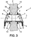
figure 3 illustre une vue en coupe longitudinale du dispositif coupe-feu de lafigure 2 . - Comme visible sur la
figure 1 , l'invention a pour objet un dispositif coupe-feu de traversée d'une paroi, référencé 1 sur les figures. - Sur les
figures 1 à 3 , le dispositif coupe-feu 1 est illustré en position installé dans une paroi ou mur, référencée 2. - La paroi 2 fait frontière entre une première zone Z et une deuxième zone Z.
- Le dispositif 1 permet la traversée de la paroi notamment par un fluide et/ou un câble électrique et/ou un conduit de fluide.
- Sur la
figure 3 , un ensemble de câbles 4 traverse la paroi 2 via le dispositif 1. - Comme visible sur les
figures 1 à 3 , le dispositif 1 comprend un manchon 5 de traversée de la paroi 2. - Le manchon 5 comprend un corps principal et au moins un orifice de passage.
- Sur le mode de réalisation illustré, et comme plus particulièrement visible à la
figure 3 , le manchon 5 comprend deux demi-fourreaux 7, 8 séparés par un intervalle 9 pour empêcher d'un pont thermique entre les deux demi-fourreaux 7, 8. - Chaque demi-fourreau 7, 8 est muni à l'une de ses extrémités d'un orifice 10 de passage de l'ensemble de câbles et/ou conduits 4.
- L'invention va maintenant être décrite en détail relativement au demi-fourreau 7.
- Bien entendu, le demi-fourreau 8 est de préférence identique au demi-fourreau 7, de sorte que la même description s'applique également au demi-fourreau 8.
- Comme visible sur les
figures 1 à 3 , le demi-fourreau 7 comprend un corps principal 12 logé dans la paroi 2, l'orifice de passage 10 étant disposé hors de la paroi 2. - Le corps principal 12 comprend une partie 13 à l'intérieur de la paroi 2, tandis qu'une partie 14 fait saillie hors d'une face 15 de la paroi 2, dans la première zone Z.
- Le corps principal 12 présente une forme générale cylindrique s'étendant dans une direction principale L.
- Le demi-fourreau 7 comprend également un volet 16 d'obturation de l'orifice de passage 10 par gravité.
- Le volet 16 est mobile entre une position d'ouverture de l'orifice de passage 10, illustrée sur la
figure 1 et une position de fermeture de l'orifice de passage 10, illustrée sur lafigure 2 . - Comme particulièrement visible sur les
figures 1 et 2 , le demi-fourreau 7 comprend une tige 17 de pivotement du volet 16 entre la position d'ouverture et la position de fermeture. - La tige 17 s'étend dans une direction parallèle à un plan P de la face 15.
- La tige 17 est disposée en regard de la partie externe 14 du corps principal 13.
- En position installé dans la paroi 2, la tige 17 est montée au-dessus du corps principal 13, ce qui assure que la position stable du volet d'obturation 16 est la position de fermeture, tandis que la position ouverte n'est jamais stable.
- Le volet d'obturation 16 comprend un couvercle 18 sur lequel repose un bouchon 19.
- Le bouchon 19 est constitué d'un matériau intumescent.
- Comme visible sur les
figures 1 à 3 , le bouchon 19 est disposé de sorte à boucher l'orifice de passage 10 en position de fermeture du volet 16. - Le couvercle 18 comprend une fourche 20 munie de deux dents 21 espacées l'une de l'autre, diamétralement opposée à la tige 17.
- Les dents 21 sont chacune perforées d'un trou 22.
- Un barreau 23 traverse les deux trous 22, l'une au moins des extrémités du barreau 23 en faisant saillie hors des trous 22.
- Le dispositif coupe-feu 1 comprend un doigt 24 solidaire de la partie externe 14 et disposé en regard de la fourche 20 de sorte qu'en position de fermeture, les dents 21 de la fourche 20 soient disposées de part et d'autre du doigt 24.
- Comme il ressort particulièrement de la
figure 1 , le dispositif coupe-feu 1 comprend un organe de commande 25 de la position du volet d'obturation 16. - L'organe de commande 25 comprend un élément thermiquement fusible 26, autrement appelé fusible thermique.
- Le fusible thermique 26 est disposé de sorte à maintenir le volet en position d'ouverture.
- Comme plus particulièrement visible sur la
figure 1 , le fusible thermique 26 comprend deux extrémités, chacune étant perforée respectivement d'un trou 27. - Une chaîne 28 relie le fusible thermique 26 au volet 16.
- Une extrémité 29 de la chaîne 28 est solidaire du fusible thermique 26, tandis qu'une extrémité 30 de la chaîne 28 est solidaire du barreau 23.
- Un arceau 31 passe dans l'autre trou 27 pour solidariser le fusible thermique 26 à la face 15 de la paroi 2.
- Comme visible sur la
figure 1 , le fusible thermique 26 solidaire du volet d'obturation 16 maintient le volet d'obturation 16 en position d'ouverture de l'orifice de passage 10. - Comme visible sur la
figure 2 , une fois que le fusible thermique 26 a fondu, en cas d'incendie, le volet n'est plus maintenu en position ouverte et retombe en position stable, c'est-à-dire en position de fermeture de l'orifice de passage 10. - Comme visible sur la
figure 1 , le dispositif coupe-feu comprend une grille 32 dans le corps principal 13 du demi-fourreau 7. - La grille 32 est montée sensiblement orthogonalement à la direction L.
- De préférence, la grille 32 comprend un revêtement de protection anti-feu.
- Le revêtement de protection anti-feu comprend préférentiellement au moins une couche de colle réfractaire.
- La colle réfractaire comprend de manière connue des éléments actifs qui libèrent de l'eau lorsque la température s'élève, par exemple au-dessus de 80°C. En se vaporisant à 100°C, cette eau ralentit la propagation de la chaleur du côté extérieur (chaud) du revêtement vers son côté intérieur (froid). On peut notamment utiliser une colle dite F.active, à base d'hydrates d'oxydes métalliques.
- Avantageusement, la grille comprend au moins une couche de matériau incombustible de type silicate de calcium.
- La couche de matériau incombustible est en contact du revêtement de protection anti-feu.
- On note qu'avantageusement des trous de la grille 32 sont suffisamment petits pour ne pas laisser passer une pige lors d'essais au feu.
- Comme visible sur les
figures 1 et 2 , le dispositif coupe-feu 1 comprend un support 33 de fixation du demi-fourreau 7 à la face 15 de la paroi 2, une plaque de matériau intumescent (non visible) formant joint entre le support de fixation 33 et la face 15. - L'invention est maintenant décrite en relation avec les deux demi-fourreaux 7, 8.
- Comme déjà indiqué, la description du demi-fourreau 8 est analogue à celle du demi-fourreau 7.
- On note que le corps principal 12 du demi-fourreau 8 s'étend dans le prolongement du corps principal 12 du demi-fourreau 7.
- En d'autres termes, chacun des cylindres 12 s'étend dans la même direction principale L.
- Les demi-fourreaux 7, 8 sont enfoncés dans un carottage 34 de la paroi 2, le demi-fourreau 7 débouchant dans la face 15 (comme déjà décrit), tandis que le demi-fourreau 8 débouche dans une face 35 de la paroi 2 et opposée de la face 15.
- L'ensemble 4 de câbles et/ou conduits pénètre le demi-fourreau 7 par l'orifice de passage 10, traverse le corps principal 13 du demi-fourreau 7, l'intervalle 9 puis le corps principal 12 du demi-fourreau 7 et sort du dispositif coupe-feu 1 par l'orifice de passage 10 du demi-fourreau 8.
- En position d'utilisation normale du dispositif coupe-feu 1, c'est-à-dire quand le dispositif coupe-feu 1 est installé dans la paroi 2 et qu'aucun incendie n'a lieu, chaque volet 16 est en position d'ouverture de l'orifice de passage associé 10.
- Dans cette position, l'air traverse le dispositif coupe-feu 1 entre les zones Z, ce qui assure une équipression entre les zones.
- En cas d'inondation, puisque chaque volet d'obturation 16 est en position d'ouverture de l'orifice de passage associé 10, l'eau circule entre les deux zones Z, ce qui permet d'éviter un niveau trop élevé dans l'une des zones.
- En cas d'incendie, du fait de l'augmentation de la température, le fusible thermique 26 fond ; chaque volet 16 tombe contre l'orifice de passage 10 associé.
- Le matériau intumescent du bouchon 19 gonfle, ce qui empêche la propagation du feu.
- La grille contribue également à ralentir le feu entre les zones Z, par les couches de matériaux la constituant.
Claims (9)
- Dispositif coupe-feu de traversée d'une paroi (2), notamment pour permettre la traversée de la paroi par un fluide et/ou un câble électrique et/ou un conduit de fluide, le dispositif comprenant un manchon (5) de traversée de paroi muni d'un corps principal (12) et d'un orifice de passage (10), notamment pour le passage de fluide, et/ou câble électrique, et/ou conduit de fluide, ledit manchon (5) étant configuré pour que le corps principal (12) soit logé au moins partiellement dans ladite paroi et l'orifice d'entrée (10) soit disposé hors de la paroi (2), le dispositif coupe-feu (1) comprenant un volet (16) d'obturation de l'orifice de passage (10) par gravité, ledit volet (16) étant monté mobile entre une position de fermeture de l'orifice de passage (10) et une position d'ouverture de l'orifice de passage (10), le dispositif (1) comprenant un organe de commande (25) de position du volet (16) entre la position d'ouverture et la position de fermeture, l'organe de commande (25) comprenant un élément thermiquement fusible (26) disposé de sorte à maintenir le volet (16) en position d'ouverture, le volet (16) étant pourvu d'un bouchon (19) en matériau intumescent, le bouchon (19) étant disposé de sorte à boucher l'orifice de passage (10) en position de fermeture du volet (16).
- Dispositif coupe-feu selon la revendication 1, comprenant une grille (32) dans le corps principal (12) du manchon (5).
- Dispositif coupe-feu selon la revendication précédente, dans lequel la grille (32) comprend un revêtement de protection anti-feu.
- Dispositif coupe-feu selon la revendication précédente, dans lequel le revêtement de protection anti-feu comprend au moins une couche de colle réfractaire, la colle comprenant des éléments actifs capables de libérer de l'eau lors d'une élévation de température.
- Dispositif coupe-feu selon l'une des revendications 2 à 4, dans lequel la grille (32) comprend au moins une couche de matériau incombustible de type silicate de calcium.
- Dispositif coupe-feu selon l'une des revendications 2 à 5, dans lequel des trous de la grille (32) sont suffisamment petits pour ne pas laisser passer une pige lors d'essais au feu.
- Dispositif coupe-feu selon l'une des revendications précédentes, comprenant un support (33) de fixation du dispositif (1) à ladite paroi (2), et une plaque de matériau intumescent formant joint entre le support de fixation du dispositif et ladite paroi.
- Dispositif coupe-feu selon l'une des revendications précédentes, dans lequel le manchon (5) comprend deux demi-fourreaux (7, 8) séparés par un intervalle (9) pour empêcher la formation d'un pont thermique, l'orifice de passage (10) formant extrémité de l'un des deux demi-fourreaux (7).
- Dispositif coupe-feu selon la revendication précédente, comprenant un deuxième orifice de sortie (10) formant extrémité de l'autre demi-fourreau (8).
Priority Applications (1)
| Application Number | Priority Date | Filing Date | Title |
|---|---|---|---|
| EP16306835.6A EP3342466B1 (fr) | 2016-12-28 | 2016-12-28 | Dispositif coupe-feu de traversee d'une paroi |
Applications Claiming Priority (1)
| Application Number | Priority Date | Filing Date | Title |
|---|---|---|---|
| EP16306835.6A EP3342466B1 (fr) | 2016-12-28 | 2016-12-28 | Dispositif coupe-feu de traversee d'une paroi |
Publications (2)
| Publication Number | Publication Date |
|---|---|
| EP3342466A1 true EP3342466A1 (fr) | 2018-07-04 |
| EP3342466B1 EP3342466B1 (fr) | 2024-08-21 |
Family
ID=57794100
Family Applications (1)
| Application Number | Title | Priority Date | Filing Date |
|---|---|---|---|
| EP16306835.6A Active EP3342466B1 (fr) | 2016-12-28 | 2016-12-28 | Dispositif coupe-feu de traversee d'une paroi |
Country Status (1)
| Country | Link |
|---|---|
| EP (1) | EP3342466B1 (fr) |
Cited By (4)
| Publication number | Priority date | Publication date | Assignee | Title |
|---|---|---|---|---|
| WO2022011419A1 (fr) * | 2020-07-14 | 2022-01-20 | Ig6 Pty Ltd | Collier coupe-feu amélioré |
| CN115954812A (zh) * | 2022-09-30 | 2023-04-11 | 广东广船国际海洋科技研究院有限公司 | 用于线缆的防火结构 |
| GB2623424A (en) * | 2022-09-05 | 2024-04-17 | Intumescent Systems Ltd | Through-wall apparatus for cabling |
| WO2025114648A1 (fr) * | 2023-11-27 | 2025-06-05 | Baumert Sasu | Dispositif coupe-feu de passage à travers une paroi et paroi équipée d'au moins un tel dispositif |
Citations (4)
| Publication number | Priority date | Publication date | Assignee | Title |
|---|---|---|---|---|
| US4857364A (en) * | 1986-12-20 | 1989-08-15 | Bayer Aktiengesellschaft | Intumescent compositions and the use thereof |
| EP0524078A1 (fr) * | 1991-07-12 | 1993-01-20 | Electricite De France | Dispositif coupe-feu de traversée d'une paroi pour le passage de conduits de liaison temporaire |
| DE10060252A1 (de) * | 2000-06-27 | 2002-01-10 | Illbruck Gmbh | Brandschutzelement |
| JP2006071264A (ja) * | 2004-08-03 | 2006-03-16 | Sekisui Chem Co Ltd | 建物の換気装置 |
Family Cites Families (1)
| Publication number | Priority date | Publication date | Assignee | Title |
|---|---|---|---|---|
| DE3218573A1 (de) * | 1982-04-14 | 1983-10-20 | Brandschutz und Service Vertriebsgesellschaft mbH, 2105 Seevetal | Feuersperre fuer rohrdurchfuehrungen |
-
2016
- 2016-12-28 EP EP16306835.6A patent/EP3342466B1/fr active Active
Patent Citations (4)
| Publication number | Priority date | Publication date | Assignee | Title |
|---|---|---|---|---|
| US4857364A (en) * | 1986-12-20 | 1989-08-15 | Bayer Aktiengesellschaft | Intumescent compositions and the use thereof |
| EP0524078A1 (fr) * | 1991-07-12 | 1993-01-20 | Electricite De France | Dispositif coupe-feu de traversée d'une paroi pour le passage de conduits de liaison temporaire |
| DE10060252A1 (de) * | 2000-06-27 | 2002-01-10 | Illbruck Gmbh | Brandschutzelement |
| JP2006071264A (ja) * | 2004-08-03 | 2006-03-16 | Sekisui Chem Co Ltd | 建物の換気装置 |
Cited By (7)
| Publication number | Priority date | Publication date | Assignee | Title |
|---|---|---|---|---|
| WO2022011419A1 (fr) * | 2020-07-14 | 2022-01-20 | Ig6 Pty Ltd | Collier coupe-feu amélioré |
| GB2623424A (en) * | 2022-09-05 | 2024-04-17 | Intumescent Systems Ltd | Through-wall apparatus for cabling |
| IE20230361A3 (en) * | 2022-09-05 | 2024-04-24 | Intumescent Systems Ltd | Through-wall apparatus for cabling |
| GB2623424B (en) * | 2022-09-05 | 2024-10-09 | Intumescent Systems Ltd | Through-wall apparatus for cabling |
| IE87697B1 (en) * | 2022-09-05 | 2026-02-11 | Intumescent Systems Ltd | Through-wall apparatus for cabling |
| CN115954812A (zh) * | 2022-09-30 | 2023-04-11 | 广东广船国际海洋科技研究院有限公司 | 用于线缆的防火结构 |
| WO2025114648A1 (fr) * | 2023-11-27 | 2025-06-05 | Baumert Sasu | Dispositif coupe-feu de passage à travers une paroi et paroi équipée d'au moins un tel dispositif |
Also Published As
| Publication number | Publication date |
|---|---|
| EP3342466B1 (fr) | 2024-08-21 |
Similar Documents
| Publication | Publication Date | Title |
|---|---|---|
| EP3342466B1 (fr) | Dispositif coupe-feu de traversee d'une paroi | |
| FR2698676A1 (fr) | Vanne thermosensible. | |
| EP4155213B1 (fr) | Aéronef comportant une canalisation de transport de dihydrogène et un canal d'enfouissement de ladite canalisation de transport | |
| WO2012056117A1 (fr) | Porte étanche et coupe feu | |
| FR2770411A1 (fr) | Clapet pare-feu pour conduit d'aeration | |
| CA1233393A (fr) | Valve d'alimentation et de decharge brutale munie d'un piston | |
| FR2805591A1 (fr) | Dispositif thermostatique a deux regimes de regulation commandes selectivement | |
| EP2655946B1 (fr) | Dispositif de commande du débit d'un fluide de refroidissement | |
| BE1018652A5 (fr) | Clapet anti-feu et anti-fumee. | |
| EP1029558B1 (fr) | Soupape de protection contre l'incendie | |
| EP0805314A1 (fr) | Obturateur de clapet, clapet muni d'un obturateur et système d'un cadre à sceller à travers une paroi et d'un clapet muni d'un obturateur à monter dans ce cadre | |
| EP2864001A1 (fr) | Systeme de clapet coupe-feu articule avec etancheite et ensemble compose de deux tels systemes | |
| EP0524078B1 (fr) | Dispositif coupe-feu de traversée d'une paroi pour le passage de conduits de liaison temporaire | |
| FR2689602A1 (fr) | Dispositif permettant de couper un circuit de fluide en cas d'incendie. | |
| FR2943752A1 (fr) | Vanne de commande pour un circuit de refroidissement d'un moteur de vehicule automobile et circuit de refroidissement comportant une telle vanne | |
| FR2686399A1 (fr) | Dispositif de chauffage ou foyer au gaz a evacuation directe et valve de securite pour lesdits dispositifs de chauffage. | |
| BE902087A (fr) | Clapet coupe-feu. | |
| WO2017021592A1 (fr) | Dispositif de clapet coupe-feu et ensemble composé d'au moins deux tels dispositifs montés en série | |
| CA2298178A1 (fr) | Dispositif de securite pour robinet a eau chaude sanitaire et robinet notamment thermostatique pourvu du dit element de securite | |
| FR2721830A1 (fr) | Clapet coupe-feu | |
| FR2800620A1 (fr) | Dispositif coupe-feu formant element de conduit | |
| WO2014128383A2 (fr) | Installation de lutte contre les incendies, incluant un réseau de sprinklers sous vide, incluant au moins une tête ouverte d'écoulement d'eau | |
| FR2733023A1 (fr) | Obturateur de clapet, clapet muni d'un obturateur et systeme d'un cadre a sceller a travers une paroi et d'un clapet muni d'un obturateur a monter dans ce cadre | |
| FR2680404A1 (fr) | Clapet anti-geyser pour tuyere d'arrosage automatique ou autres arroseurs escamotables ou non. | |
| FR2739033A1 (fr) | Installation de ventilation |
Legal Events
| Date | Code | Title | Description |
|---|---|---|---|
| PUAI | Public reference made under article 153(3) epc to a published international application that has entered the european phase |
Free format text: ORIGINAL CODE: 0009012 |
|
| STAA | Information on the status of an ep patent application or granted ep patent |
Free format text: STATUS: THE APPLICATION HAS BEEN PUBLISHED |
|
| STAA | Information on the status of an ep patent application or granted ep patent |
Free format text: STATUS: REQUEST FOR EXAMINATION WAS MADE |
|
| AK | Designated contracting states |
Kind code of ref document: A1 Designated state(s): AL AT BE BG CH CY CZ DE DK EE ES FI FR GB GR HR HU IE IS IT LI LT LU LV MC MK MT NL NO PL PT RO RS SE SI SK SM TR |
|
| AX | Request for extension of the european patent |
Extension state: BA ME |
|
| 17P | Request for examination filed |
Effective date: 20180612 |
|
| RBV | Designated contracting states (corrected) |
Designated state(s): AL AT BE BG CH CY CZ DE DK EE ES FI FR GB GR HR HU IE IS IT LI LT LU LV MC MK MT NL NO PL PT RO RS SE SI SK SM TR |
|
| STAA | Information on the status of an ep patent application or granted ep patent |
Free format text: STATUS: EXAMINATION IS IN PROGRESS |
|
| 17Q | First examination report despatched |
Effective date: 20200608 |
|
| P01 | Opt-out of the competence of the unified patent court (upc) registered |
Effective date: 20230526 |
|
| GRAP | Despatch of communication of intention to grant a patent |
Free format text: ORIGINAL CODE: EPIDOSNIGR1 |
|
| STAA | Information on the status of an ep patent application or granted ep patent |
Free format text: STATUS: GRANT OF PATENT IS INTENDED |
|
| INTG | Intention to grant announced |
Effective date: 20240318 |
|
| GRAS | Grant fee paid |
Free format text: ORIGINAL CODE: EPIDOSNIGR3 |
|
| GRAA | (expected) grant |
Free format text: ORIGINAL CODE: 0009210 |
|
| STAA | Information on the status of an ep patent application or granted ep patent |
Free format text: STATUS: THE PATENT HAS BEEN GRANTED |
|
| AK | Designated contracting states |
Kind code of ref document: B1 Designated state(s): AL AT BE BG CH CY CZ DE DK EE ES FI FR GB GR HR HU IE IS IT LI LT LU LV MC MK MT NL NO PL PT RO RS SE SI SK SM TR |
|
| REG | Reference to a national code |
Ref country code: GB Ref legal event code: FG4D Free format text: NOT ENGLISH |
|
| REG | Reference to a national code |
Ref country code: CH Ref legal event code: EP |
|
| REG | Reference to a national code |
Ref country code: IE Ref legal event code: FG4D Free format text: LANGUAGE OF EP DOCUMENT: FRENCH |
|
| REG | Reference to a national code |
Ref country code: DE Ref legal event code: R096 Ref document number: 602016088976 Country of ref document: DE |
|
| REG | Reference to a national code |
Ref country code: LT Ref legal event code: MG9D |
|
| REG | Reference to a national code |
Ref country code: NL Ref legal event code: MP Effective date: 20240821 |
|
| PG25 | Lapsed in a contracting state [announced via postgrant information from national office to epo] |
Ref country code: NO Free format text: LAPSE BECAUSE OF FAILURE TO SUBMIT A TRANSLATION OF THE DESCRIPTION OR TO PAY THE FEE WITHIN THE PRESCRIBED TIME-LIMIT Effective date: 20241121 |
|
| REG | Reference to a national code |
Ref country code: AT Ref legal event code: MK05 Ref document number: 1714972 Country of ref document: AT Kind code of ref document: T Effective date: 20240821 |
|
| PG25 | Lapsed in a contracting state [announced via postgrant information from national office to epo] |
Ref country code: GR Free format text: LAPSE BECAUSE OF FAILURE TO SUBMIT A TRANSLATION OF THE DESCRIPTION OR TO PAY THE FEE WITHIN THE PRESCRIBED TIME-LIMIT Effective date: 20241122 Ref country code: FI Free format text: LAPSE BECAUSE OF FAILURE TO SUBMIT A TRANSLATION OF THE DESCRIPTION OR TO PAY THE FEE WITHIN THE PRESCRIBED TIME-LIMIT Effective date: 20240821 Ref country code: PT Free format text: LAPSE BECAUSE OF FAILURE TO SUBMIT A TRANSLATION OF THE DESCRIPTION OR TO PAY THE FEE WITHIN THE PRESCRIBED TIME-LIMIT Effective date: 20241223 Ref country code: PL Free format text: LAPSE BECAUSE OF FAILURE TO SUBMIT A TRANSLATION OF THE DESCRIPTION OR TO PAY THE FEE WITHIN THE PRESCRIBED TIME-LIMIT Effective date: 20240821 Ref country code: NL Free format text: LAPSE BECAUSE OF FAILURE TO SUBMIT A TRANSLATION OF THE DESCRIPTION OR TO PAY THE FEE WITHIN THE PRESCRIBED TIME-LIMIT Effective date: 20240821 |
|
| PG25 | Lapsed in a contracting state [announced via postgrant information from national office to epo] |
Ref country code: BG Free format text: LAPSE BECAUSE OF FAILURE TO SUBMIT A TRANSLATION OF THE DESCRIPTION OR TO PAY THE FEE WITHIN THE PRESCRIBED TIME-LIMIT Effective date: 20240821 |
|
| PG25 | Lapsed in a contracting state [announced via postgrant information from national office to epo] |
Ref country code: LV Free format text: LAPSE BECAUSE OF FAILURE TO SUBMIT A TRANSLATION OF THE DESCRIPTION OR TO PAY THE FEE WITHIN THE PRESCRIBED TIME-LIMIT Effective date: 20240821 |
|
| PG25 | Lapsed in a contracting state [announced via postgrant information from national office to epo] |
Ref country code: AT Free format text: LAPSE BECAUSE OF FAILURE TO SUBMIT A TRANSLATION OF THE DESCRIPTION OR TO PAY THE FEE WITHIN THE PRESCRIBED TIME-LIMIT Effective date: 20240821 Ref country code: IS Free format text: LAPSE BECAUSE OF FAILURE TO SUBMIT A TRANSLATION OF THE DESCRIPTION OR TO PAY THE FEE WITHIN THE PRESCRIBED TIME-LIMIT Effective date: 20241221 |
|
| PG25 | Lapsed in a contracting state [announced via postgrant information from national office to epo] |
Ref country code: HR Free format text: LAPSE BECAUSE OF FAILURE TO SUBMIT A TRANSLATION OF THE DESCRIPTION OR TO PAY THE FEE WITHIN THE PRESCRIBED TIME-LIMIT Effective date: 20240821 |
|
| PG25 | Lapsed in a contracting state [announced via postgrant information from national office to epo] |
Ref country code: RS Free format text: LAPSE BECAUSE OF FAILURE TO SUBMIT A TRANSLATION OF THE DESCRIPTION OR TO PAY THE FEE WITHIN THE PRESCRIBED TIME-LIMIT Effective date: 20241121 Ref country code: ES Free format text: LAPSE BECAUSE OF FAILURE TO SUBMIT A TRANSLATION OF THE DESCRIPTION OR TO PAY THE FEE WITHIN THE PRESCRIBED TIME-LIMIT Effective date: 20240821 |
|
| PG25 | Lapsed in a contracting state [announced via postgrant information from national office to epo] |
Ref country code: RS Free format text: LAPSE BECAUSE OF FAILURE TO SUBMIT A TRANSLATION OF THE DESCRIPTION OR TO PAY THE FEE WITHIN THE PRESCRIBED TIME-LIMIT Effective date: 20241121 Ref country code: PT Free format text: LAPSE BECAUSE OF FAILURE TO SUBMIT A TRANSLATION OF THE DESCRIPTION OR TO PAY THE FEE WITHIN THE PRESCRIBED TIME-LIMIT Effective date: 20241223 Ref country code: PL Free format text: LAPSE BECAUSE OF FAILURE TO SUBMIT A TRANSLATION OF THE DESCRIPTION OR TO PAY THE FEE WITHIN THE PRESCRIBED TIME-LIMIT Effective date: 20240821 Ref country code: NO Free format text: LAPSE BECAUSE OF FAILURE TO SUBMIT A TRANSLATION OF THE DESCRIPTION OR TO PAY THE FEE WITHIN THE PRESCRIBED TIME-LIMIT Effective date: 20241121 Ref country code: NL Free format text: LAPSE BECAUSE OF FAILURE TO SUBMIT A TRANSLATION OF THE DESCRIPTION OR TO PAY THE FEE WITHIN THE PRESCRIBED TIME-LIMIT Effective date: 20240821 Ref country code: LV Free format text: LAPSE BECAUSE OF FAILURE TO SUBMIT A TRANSLATION OF THE DESCRIPTION OR TO PAY THE FEE WITHIN THE PRESCRIBED TIME-LIMIT Effective date: 20240821 Ref country code: IS Free format text: LAPSE BECAUSE OF FAILURE TO SUBMIT A TRANSLATION OF THE DESCRIPTION OR TO PAY THE FEE WITHIN THE PRESCRIBED TIME-LIMIT Effective date: 20241221 Ref country code: HR Free format text: LAPSE BECAUSE OF FAILURE TO SUBMIT A TRANSLATION OF THE DESCRIPTION OR TO PAY THE FEE WITHIN THE PRESCRIBED TIME-LIMIT Effective date: 20240821 Ref country code: GR Free format text: LAPSE BECAUSE OF FAILURE TO SUBMIT A TRANSLATION OF THE DESCRIPTION OR TO PAY THE FEE WITHIN THE PRESCRIBED TIME-LIMIT Effective date: 20241122 Ref country code: FI Free format text: LAPSE BECAUSE OF FAILURE TO SUBMIT A TRANSLATION OF THE DESCRIPTION OR TO PAY THE FEE WITHIN THE PRESCRIBED TIME-LIMIT Effective date: 20240821 Ref country code: ES Free format text: LAPSE BECAUSE OF FAILURE TO SUBMIT A TRANSLATION OF THE DESCRIPTION OR TO PAY THE FEE WITHIN THE PRESCRIBED TIME-LIMIT Effective date: 20240821 Ref country code: BG Free format text: LAPSE BECAUSE OF FAILURE TO SUBMIT A TRANSLATION OF THE DESCRIPTION OR TO PAY THE FEE WITHIN THE PRESCRIBED TIME-LIMIT Effective date: 20240821 Ref country code: AT Free format text: LAPSE BECAUSE OF FAILURE TO SUBMIT A TRANSLATION OF THE DESCRIPTION OR TO PAY THE FEE WITHIN THE PRESCRIBED TIME-LIMIT Effective date: 20240821 |
|
| PG25 | Lapsed in a contracting state [announced via postgrant information from national office to epo] |
Ref country code: RO Free format text: LAPSE BECAUSE OF FAILURE TO SUBMIT A TRANSLATION OF THE DESCRIPTION OR TO PAY THE FEE WITHIN THE PRESCRIBED TIME-LIMIT Effective date: 20240821 Ref country code: SM Free format text: LAPSE BECAUSE OF FAILURE TO SUBMIT A TRANSLATION OF THE DESCRIPTION OR TO PAY THE FEE WITHIN THE PRESCRIBED TIME-LIMIT Effective date: 20240821 Ref country code: DK Free format text: LAPSE BECAUSE OF FAILURE TO SUBMIT A TRANSLATION OF THE DESCRIPTION OR TO PAY THE FEE WITHIN THE PRESCRIBED TIME-LIMIT Effective date: 20240821 |
|
| PG25 | Lapsed in a contracting state [announced via postgrant information from national office to epo] |
Ref country code: EE Free format text: LAPSE BECAUSE OF FAILURE TO SUBMIT A TRANSLATION OF THE DESCRIPTION OR TO PAY THE FEE WITHIN THE PRESCRIBED TIME-LIMIT Effective date: 20240821 |
|
| PG25 | Lapsed in a contracting state [announced via postgrant information from national office to epo] |
Ref country code: CZ Free format text: LAPSE BECAUSE OF FAILURE TO SUBMIT A TRANSLATION OF THE DESCRIPTION OR TO PAY THE FEE WITHIN THE PRESCRIBED TIME-LIMIT Effective date: 20240821 |
|
| PG25 | Lapsed in a contracting state [announced via postgrant information from national office to epo] |
Ref country code: SK Free format text: LAPSE BECAUSE OF FAILURE TO SUBMIT A TRANSLATION OF THE DESCRIPTION OR TO PAY THE FEE WITHIN THE PRESCRIBED TIME-LIMIT Effective date: 20240821 Ref country code: IT Free format text: LAPSE BECAUSE OF FAILURE TO SUBMIT A TRANSLATION OF THE DESCRIPTION OR TO PAY THE FEE WITHIN THE PRESCRIBED TIME-LIMIT Effective date: 20240821 |
|
| REG | Reference to a national code |
Ref country code: DE Ref legal event code: R097 Ref document number: 602016088976 Country of ref document: DE |
|
| PLBE | No opposition filed within time limit |
Free format text: ORIGINAL CODE: 0009261 |
|
| STAA | Information on the status of an ep patent application or granted ep patent |
Free format text: STATUS: NO OPPOSITION FILED WITHIN TIME LIMIT |
|
| REG | Reference to a national code |
Ref country code: DE Ref legal event code: R119 Ref document number: 602016088976 Country of ref document: DE |
|
| PG25 | Lapsed in a contracting state [announced via postgrant information from national office to epo] |
Ref country code: MC Free format text: LAPSE BECAUSE OF FAILURE TO SUBMIT A TRANSLATION OF THE DESCRIPTION OR TO PAY THE FEE WITHIN THE PRESCRIBED TIME-LIMIT Effective date: 20240821 |
|
| 26N | No opposition filed |
Effective date: 20250522 |
|
| REG | Reference to a national code |
Ref country code: CH Ref legal event code: PL |
|
| PG25 | Lapsed in a contracting state [announced via postgrant information from national office to epo] |
Ref country code: LU Free format text: LAPSE BECAUSE OF NON-PAYMENT OF DUE FEES Effective date: 20241228 |
|
| PG25 | Lapsed in a contracting state [announced via postgrant information from national office to epo] |
Ref country code: SE Free format text: LAPSE BECAUSE OF FAILURE TO SUBMIT A TRANSLATION OF THE DESCRIPTION OR TO PAY THE FEE WITHIN THE PRESCRIBED TIME-LIMIT Effective date: 20240821 |
|
| REG | Reference to a national code |
Ref country code: BE Ref legal event code: MM Effective date: 20241231 |
|
| PG25 | Lapsed in a contracting state [announced via postgrant information from national office to epo] |
Ref country code: DE Free format text: LAPSE BECAUSE OF NON-PAYMENT OF DUE FEES Effective date: 20250701 |
|
| PG25 | Lapsed in a contracting state [announced via postgrant information from national office to epo] |
Ref country code: BE Free format text: LAPSE BECAUSE OF NON-PAYMENT OF DUE FEES Effective date: 20241231 |
|
| PG25 | Lapsed in a contracting state [announced via postgrant information from national office to epo] |
Ref country code: CH Free format text: LAPSE BECAUSE OF NON-PAYMENT OF DUE FEES Effective date: 20241231 |
|
| PG25 | Lapsed in a contracting state [announced via postgrant information from national office to epo] |
Ref country code: IE Free format text: LAPSE BECAUSE OF NON-PAYMENT OF DUE FEES Effective date: 20241228 |
|
| PGFP | Annual fee paid to national office [announced via postgrant information from national office to epo] |
Ref country code: GB Payment date: 20251119 Year of fee payment: 10 |
|
| PGFP | Annual fee paid to national office [announced via postgrant information from national office to epo] |
Ref country code: FR Payment date: 20251120 Year of fee payment: 10 |
|
| PG25 | Lapsed in a contracting state [announced via postgrant information from national office to epo] |
Ref country code: CY Free format text: LAPSE BECAUSE OF FAILURE TO SUBMIT A TRANSLATION OF THE DESCRIPTION OR TO PAY THE FEE WITHIN THE PRESCRIBED TIME-LIMIT Effective date: 20240821 |
|
| PG25 | Lapsed in a contracting state [announced via postgrant information from national office to epo] |
Ref country code: TR Free format text: LAPSE BECAUSE OF FAILURE TO SUBMIT A TRANSLATION OF THE DESCRIPTION OR TO PAY THE FEE WITHIN THE PRESCRIBED TIME-LIMIT Effective date: 20240821 |
|
| PG25 | Lapsed in a contracting state [announced via postgrant information from national office to epo] |
Ref country code: HU Free format text: LAPSE BECAUSE OF FAILURE TO SUBMIT A TRANSLATION OF THE DESCRIPTION OR TO PAY THE FEE WITHIN THE PRESCRIBED TIME-LIMIT; INVALID AB INITIO Effective date: 20161228 |
|
| PG25 | Lapsed in a contracting state [announced via postgrant information from national office to epo] |
Ref country code: SI Free format text: LAPSE BECAUSE OF FAILURE TO SUBMIT A TRANSLATION OF THE DESCRIPTION OR TO PAY THE FEE WITHIN THE PRESCRIBED TIME-LIMIT Effective date: 20240821 |
|
| PG25 | Lapsed in a contracting state [announced via postgrant information from national office to epo] |
Ref country code: LT Free format text: LAPSE BECAUSE OF FAILURE TO SUBMIT A TRANSLATION OF THE DESCRIPTION OR TO PAY THE FEE WITHIN THE PRESCRIBED TIME-LIMIT Effective date: 20240821 |