EP3342429A1 - Sterilization system and method having a thermodynamic cycle - Google Patents
Sterilization system and method having a thermodynamic cycle Download PDFInfo
- Publication number
- EP3342429A1 EP3342429A1 EP17210371.5A EP17210371A EP3342429A1 EP 3342429 A1 EP3342429 A1 EP 3342429A1 EP 17210371 A EP17210371 A EP 17210371A EP 3342429 A1 EP3342429 A1 EP 3342429A1
- Authority
- EP
- European Patent Office
- Prior art keywords
- condenser
- sterilization
- chamber
- steam
- valve
- Prior art date
- Legal status (The legal status is an assumption and is not a legal conclusion. Google has not performed a legal analysis and makes no representation as to the accuracy of the status listed.)
- Granted
Links
- 230000001954 sterilising effect Effects 0.000 title claims abstract description 81
- 238000004659 sterilization and disinfection Methods 0.000 title claims abstract description 81
- 238000000034 method Methods 0.000 title claims abstract description 24
- 238000004891 communication Methods 0.000 claims abstract description 16
- 238000001035 drying Methods 0.000 claims description 10
- 239000012530 fluid Substances 0.000 claims description 9
- 238000009833 condensation Methods 0.000 claims description 6
- 230000005494 condensation Effects 0.000 claims description 6
- 238000002347 injection Methods 0.000 claims description 6
- 239000007924 injection Substances 0.000 claims description 6
- 238000001816 cooling Methods 0.000 claims description 5
- XLYOFNOQVPJJNP-UHFFFAOYSA-N water Substances O XLYOFNOQVPJJNP-UHFFFAOYSA-N 0.000 description 14
- 230000008569 process Effects 0.000 description 11
- 239000003570 air Substances 0.000 description 6
- 230000009467 reduction Effects 0.000 description 5
- 239000007788 liquid Substances 0.000 description 3
- 239000002699 waste material Substances 0.000 description 3
- 238000010793 Steam injection (oil industry) Methods 0.000 description 2
- 230000000694 effects Effects 0.000 description 2
- 230000009471 action Effects 0.000 description 1
- 239000012080 ambient air Substances 0.000 description 1
- 230000002051 biphasic effect Effects 0.000 description 1
- 230000008859 change Effects 0.000 description 1
- 230000001419 dependent effect Effects 0.000 description 1
- 238000011038 discontinuous diafiltration by volume reduction Methods 0.000 description 1
- 238000010438 heat treatment Methods 0.000 description 1
- 230000003993 interaction Effects 0.000 description 1
- 210000004072 lung Anatomy 0.000 description 1
- 238000012423 maintenance Methods 0.000 description 1
- 238000004519 manufacturing process Methods 0.000 description 1
- 238000011017 operating method Methods 0.000 description 1
- 238000002360 preparation method Methods 0.000 description 1
- 238000004321 preservation Methods 0.000 description 1
- 230000000750 progressive effect Effects 0.000 description 1
- 238000007789 sealing Methods 0.000 description 1
- 238000003860 storage Methods 0.000 description 1
- 239000002351 wastewater Substances 0.000 description 1
Images


Classifications
-
- A—HUMAN NECESSITIES
- A61—MEDICAL OR VETERINARY SCIENCE; HYGIENE
- A61L—METHODS OR APPARATUS FOR STERILISING MATERIALS OR OBJECTS IN GENERAL; DISINFECTION, STERILISATION OR DEODORISATION OF AIR; CHEMICAL ASPECTS OF BANDAGES, DRESSINGS, ABSORBENT PADS OR SURGICAL ARTICLES; MATERIALS FOR BANDAGES, DRESSINGS, ABSORBENT PADS OR SURGICAL ARTICLES
- A61L2/00—Methods or apparatus for disinfecting or sterilising materials or objects other than foodstuffs or contact lenses; Accessories therefor
- A61L2/02—Methods or apparatus for disinfecting or sterilising materials or objects other than foodstuffs or contact lenses; Accessories therefor using physical phenomena
- A61L2/04—Heat
- A61L2/06—Hot gas
- A61L2/07—Steam
-
- A—HUMAN NECESSITIES
- A61—MEDICAL OR VETERINARY SCIENCE; HYGIENE
- A61L—METHODS OR APPARATUS FOR STERILISING MATERIALS OR OBJECTS IN GENERAL; DISINFECTION, STERILISATION OR DEODORISATION OF AIR; CHEMICAL ASPECTS OF BANDAGES, DRESSINGS, ABSORBENT PADS OR SURGICAL ARTICLES; MATERIALS FOR BANDAGES, DRESSINGS, ABSORBENT PADS OR SURGICAL ARTICLES
- A61L2/00—Methods or apparatus for disinfecting or sterilising materials or objects other than foodstuffs or contact lenses; Accessories therefor
- A61L2/26—Accessories or devices or components used for biocidal treatment
-
- A—HUMAN NECESSITIES
- A61—MEDICAL OR VETERINARY SCIENCE; HYGIENE
- A61L—METHODS OR APPARATUS FOR STERILISING MATERIALS OR OBJECTS IN GENERAL; DISINFECTION, STERILISATION OR DEODORISATION OF AIR; CHEMICAL ASPECTS OF BANDAGES, DRESSINGS, ABSORBENT PADS OR SURGICAL ARTICLES; MATERIALS FOR BANDAGES, DRESSINGS, ABSORBENT PADS OR SURGICAL ARTICLES
- A61L2202/00—Aspects relating to methods or apparatus for disinfecting or sterilising materials or objects
- A61L2202/10—Apparatus features
- A61L2202/14—Means for controlling sterilisation processes, data processing, presentation and storage means, e.g. sensors, controllers, programs
-
- A—HUMAN NECESSITIES
- A61—MEDICAL OR VETERINARY SCIENCE; HYGIENE
- A61L—METHODS OR APPARATUS FOR STERILISING MATERIALS OR OBJECTS IN GENERAL; DISINFECTION, STERILISATION OR DEODORISATION OF AIR; CHEMICAL ASPECTS OF BANDAGES, DRESSINGS, ABSORBENT PADS OR SURGICAL ARTICLES; MATERIALS FOR BANDAGES, DRESSINGS, ABSORBENT PADS OR SURGICAL ARTICLES
- A61L2202/00—Aspects relating to methods or apparatus for disinfecting or sterilising materials or objects
- A61L2202/20—Targets to be treated
- A61L2202/24—Medical instruments, e.g. endoscopes, catheters, sharps
Definitions
- the present invention relates to a sterilization system for various applications, e.g. autoclaves, thermodisinfectors, pasteurisers, dryers and so on.
- the invention relates to such a system with an improved thermodynamic cycle and the related operating method.
- the autoclaves In medical clinics, particularly in dental clinics, it has long been known that small size autoclaves are used to sterilize small manual tools or dental handpieces.
- the autoclaves usually have a sterilization chamber, which is for the most part empty and provided with appropriate equipment (such as baskets, trays or storage compartments) to house the devices to be sterilized (i.e. the workload).
- the chamber is provided with an opening to introduce the load and can be tightly closed (sealed) to carry out the desired sterilization cycle.
- the sterilization process takes place according to typical cycles, often compliant with a standard, with the aid of equipment and operation devices for the sterilization chamber. Typically, even if this should not be considered as a limitation, the following devices are provided:
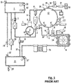
- An exemplary autoclave of this type is known from EP 992.247 , whose circuit scheme is shown in Fig. 1 as an example of prior art.
- a sterilization process normally involves - after the autoclave loading and its sealing - an emptying cycle of the sterilization chamber air, a pressurization cycle of the chamber with high temperature (about 120°-145°C) and pressure (up to about 2-3 bar) steam and finally an emptying cycle of the chamber and subsequent drying.
- the pressurization cycle the actual sterilization of the tools takes place inside the chamber, while the final phase of emptying and drying is used to ensure a perfect drying of the tools for their proper preservation.
- This general operation process is an example of what actually takes place, because there are many operation variations to achieve a greater efficiency of the process and optimal energy yields.
- vacuum pump which is used to achieve the emptying of the sterilization chamber.
- This device besides involving a cost, often causes problems, both because it has moving elements - therefore subject to wear and/or fatigue - and because it treats a fluid (steam) that can undergo changes in status (from gaseous to liquid) with inevitable associated problems (due to the biphasic flow).
- GB 1137409 describes a sterilization system where a complex hydraulic circuit is used with related water tanks, in order to obtain a pressure reduction.
- the system is complex and difficult to implement and control.
- GB 993.883 discloses another autoclave system where a generator is connected both to the sterilization chamber and to a condenser immersed in a water tank. This configuration is intended to regulate the water level in the generator to prevent the heating elements from being exposed, but does not provide any fluid-dynamic interaction between the generator and the condenser.
- DE102012010739 shows another autoclave system, wherein a condenser is partly in communication with a steam generator, but the evacuation of the sterilization chamber is still determined by vacuum pumps.
- WO00/59553 and EP852146 illustrate other autoclave configurations with sterilization cycles which still only use vacuum pumps to evacuate the sterilization chamber.
- EP 992.247 owned by the same applicant, describes a further autoclave circuit wherein a separated small cold lung of the system is used to cooperate in the emptying of the sterilization chamber.
- the applicant has the aim of providing a sterilization system and a related operation process, which could achieve a good operation of the sterilization cycle and in particular the emptying of the sterilization chamber, eliminating or reducing the contribution of a vacuum pump and modifying to the minimum necessary the existing circuits for traditional autoclaves provided with vacuum pump.
- the object of the present invention is therefore to overcome the aforementioned drawbacks by providing a steam sterilization system and an operation process which can complete a sterilization cycle without need for a mechanical vacuum pump.
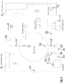
- the scheme of Fig. 2 shows the main component of an autoclave, which is taken as an exemplary scheme of a steam sterilization system.
- a sterilization chamber 1 is in the form of a sealingly closable container, able to withstand the sterilization pressure, generally cylindrical in shape. Chamber 1 is generally heated by various systems.
- Fittings are provided on the wall of the container 1 to connect the interior of the chamber 1 to a series of operating devices.
- the container 1 is provided, at least, with an inlet connector 1a and with discharge means 1b.
- the inlet connector 1a is intended to be connected to a steam generator 2, through the related pipe 1a' and a controlled inlet valve 2a, from which it receives sterilization steam.
- the discharge means 1b are intended to be connected to a condenser 3, through the related pipe 1b' and controlled discharge valve 3a, in which the steam coming out from the sterilization chamber is typically condensed.
- the inlet 2a and discharge valves 3a are in the form of two separate three-way electrovalves.
- a loading inlet 2b connects the generator 2 to a first port 2a 1 of the inlet valve 2a, then a junction pipe 2c is provided which connects a second port 2a 2 of the valve 2a to a second port 3a 2 of the valve 3a and, finally, a discharge pipe 3b is provided which connects a first port 3a 1 of the valve 3a to the condenser 3.
- the two valves 2a and 3a are then connected respectively to the pipes 1a' and 1b' through the respective third ports 2a 3 and 3a 3 .
- vent connector 1c On the wall of the chamber 1 a vent connector 1c is also provided for the connection to an air intake 4, provided with a suitable filter, suitable to allow ambient air to flow into the chamber, to rebalance the pressure before opening the autoclave.
- an air intake 4 provided with a suitable filter, suitable to allow ambient air to flow into the chamber, to rebalance the pressure before opening the autoclave.
- a controlled vent valve 4a is provided along a connection pipe 1c' between the vent connector 1c and the air intake 4.
- the sterilization chamber 1 can have connectors to a pressure sensor, a safety overpressure valve, a temperature sensor and more.
- the condenser 3 is also connected to a first tank S 1 of the waste used water through a discharge valve 3c, preferably a check valve or a non-return valve with automatic operation.
- a discharge valve 3c places the condenser 3 in communication with the ambient pressure and, when it is closed, it isolates the condenser from the external environment.
- a second tank S 2 of clean water is connected to a water pump 5. The latter is controlled so as to inject water into the steam generator 2 as required.
- an arrangement in which the steam generator 2 can be connected directly (i.e. without any other equipment having a thermodynamic effect on steam) to the condenser 3 to introduce steam.
- the condenser is isolated from the external environment by means of the discharge valve 3c, so that the cooling of the steam inside it results in a reduction in pressure of the circuit including the condenser which can be used to empty the sterilization chamber 1 when the latter is placed in communication with the condenser 3.
- the pressure reduction in the condenser 3, when the discharge valve 3c is closed can preferably be achieved (but it is not the only possible mode) by completely separating/isolating the condenser 3 also from the sterilization chamber 1 and from the generator 2, by means of appropriate valves.
- the steam condensation causes a pressure and volume reduction thereof in the condenser 3 and chamber 1 system, suitably isolated from the electrovalves 2a and 3a.
- the continuous change in state of the vapour, from gaseous to liquid, in the condenser causes a flow between chamber 1 and condenser 3 which stops when the system has reached the pressure equilibrium. According to the invention, this flow is cyclically restarted, allowing to reach ever lower pressure levels (which correspond to higher emptying levels of the sterilization chamber 1).
- connections and the valves are arranged to be able to isolate chamber 1, generator 2 and condenser 3 between them in specific phases of the process and therefore establish low pressure cycles in the condenser 3 which allow to evacuate the sterilization chamber 1 without resorting to a mechanical pump.
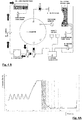
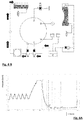
- Fig. 3 shows a graph representing the pressure with respect to time within the sterilization chamber 1, during an exemplary process of the invention.
- a preliminary phase is provided with a preheating step PHE and an air evacuation step PG obtained with pressure pulses in the sterilization chamber 1.
- a first step PPH of temperature (for example up to 145°C) and pressure (for example up to 3 bar) increase and then the maintenance of a plateau condition PR for the time necessary to complete the sterilization.
- the chamber 1 is isolated from the generator 2 (valve 2a placed in position 1-2, i.e. communication between the ports 2a 1 and 2a 2 ) and it is put into communication with the condenser 3 (valve 3a placed in position 1-3), connected in turn to the discharge towards the first waste water tank S 1 (see Fig. 4B ).
- the residual high pressure (e.g. 3 barA) in chamber 1 tends to quickly balance with the ambient pressure existing in the condenser 3.
- the valve 3a is switched so as to put the sterilization chamber 1 in communication with the condenser 3, possibly also isolating the generator 2 through the valve 2a.
- the condenser begins to cool the steam, there is a reduction in volume and therefore in pressure ( Fig. 7A ); the valve 3c is closed (or closes automatically if it is in the form of a check valve) and while the steam cools and condenses, the circuit including the condenser begins to go at low pressure.
- the pressure inside the condenser 3 stabilizes at a value lower than the ambient atmospheric pressure and the existing one in the sterilization chamber 1, thus producing a progressive emptying of the latter.
- the method of the invention provides for injecting steam directly from the generator 2 to the condenser 3 - i.e. a device designed for cooling and condensing the steam up to the liquid state - in which, due to the cooling of the steam in the gaseous state, it is possible to determine a reduction in the volume of the fluid and therefore a lowering of pressure: once it is placed in communication with the sterilization chamber, it acts as a point of low pressure for the emptying and drying of the sterilization chamber.
- the condenser 3 i.e. a device designed for cooling and condensing the steam up to the liquid state - in which, due to the cooling of the steam in the gaseous state, it is possible to determine a reduction in the volume of the fluid and therefore a lowering of pressure: once it is placed in communication with the sterilization chamber, it acts as a point of low pressure for the emptying and drying of the sterilization chamber.
- the steam injection into the condenser can be carried out at different stages of the sterilization cycle, preferably in a phase in which the sterilization chamber 1 is isolated both from the generator 2 and from the condenser 3.
- thermodynamic emptying cycle even in any phase before the sterilization phase, for example immediately after closing the autoclave to eliminate the air inside the chamber (air that has insulating properties and makes the action of steam on the devices to be sterilized less effective - especially if they are porous or with internal cavities).
Abstract
- said chamber (1) is isolated from said condenser (3),
- at least a steam generator (2) is operated to inject a predetermined amount of heated steam directly into said condenser (3),
- said steam in the condenser (3) is cooled and condensed, so as to reduce its volume and accordingly lower the pressure within said condenser (3) to below that present in said sterilization chamber,
- said condenser (3) is placed in communication with said sterilization chamber (1) to perform an evacuation.
Description
- The present invention relates to a sterilization system for various applications, e.g. autoclaves, thermodisinfectors, pasteurisers, dryers and so on. In particular, the invention relates to such a system with an improved thermodynamic cycle and the related operating method.
- Although the principles offered here may relate to any sterilization system where high-temperature steam is used, for sake of convenience we will refer almost exclusively to an ambulatory autoclave (e.g., for use in dental and veterinary clinics, for tattoo artists and beauticians), but it is to be understood that this does not limit the scope of the application of the invention.
- In medical clinics, particularly in dental clinics, it has long been known that small size autoclaves are used to sterilize small manual tools or dental handpieces. The autoclaves usually have a sterilization chamber, which is for the most part empty and provided with appropriate equipment (such as baskets, trays or storage compartments) to house the devices to be sterilized (i.e. the workload). The chamber is provided with an opening to introduce the load and can be tightly closed (sealed) to carry out the desired sterilization cycle.
- The sterilization process takes place according to typical cycles, often compliant with a standard, with the aid of equipment and operation devices for the sterilization chamber. Typically, even if this should not be considered as a limitation, the following devices are provided:
- a pair of water tanks, one for clean water, which is picked up to produce the steam and one for waste (used) water, deriving from the condensation of the steam;
- a pump to move the water;
- a steam generator, in which clean water is injected to produce the steam that acts as a working fluid;
- a condenser, to carry out the steam condensation and its related discharge towards the collection waste tank;
- a vacuum pump, intended to empty the sterilization chamber;
- and a series of electrovalves and ducts to put the equipments and devices in communication each other in the desired modes and times.
- An exemplary autoclave of this type is known from
EP 992.247 Fig. 1 as an example of prior art. - A sterilization process normally involves - after the autoclave loading and its sealing - an emptying cycle of the sterilization chamber air, a pressurization cycle of the chamber with high temperature (about 120°-145°C) and pressure (up to about 2-3 bar) steam and finally an emptying cycle of the chamber and subsequent drying. In the pressurization cycle, the actual sterilization of the tools takes place inside the chamber, while the final phase of emptying and drying is used to ensure a perfect drying of the tools for their proper preservation.
- This general operation process is an example of what actually takes place, because there are many operation variations to achieve a greater efficiency of the process and optimal energy yields.
- One of the most critical and expensive components in an autoclave is the vacuum pump, which is used to achieve the emptying of the sterilization chamber. This device, besides involving a cost, often causes problems, both because it has moving elements - therefore subject to wear and/or fatigue - and because it treats a fluid (steam) that can undergo changes in status (from gaseous to liquid) with inevitable associated problems (due to the biphasic flow).
- In the past, it has already been proposed to produce vacuum in the sterilization system using fluids, rather than a vacuum pump. For exemple
GB 1137409 -
GB 993.883 DE102012010739 shows another autoclave system, wherein a condenser is partly in communication with a steam generator, but the evacuation of the sterilization chamber is still determined by vacuum pumps.WO00/59553 EP852146 EP 992.247 - The applicant has the aim of providing a sterilization system and a related operation process, which could achieve a good operation of the sterilization cycle and in particular the emptying of the sterilization chamber, eliminating or reducing the contribution of a vacuum pump and modifying to the minimum necessary the existing circuits for traditional autoclaves provided with vacuum pump.
- The object of the present invention is therefore to overcome the aforementioned drawbacks by providing a steam sterilization system and an operation process which can complete a sterilization cycle without need for a mechanical vacuum pump.
- Such object is achieved by means of an equipment and a method as described in their essential features in the appended main claims.
- Other inventive aspects of the invention are described in the dependent claims.
- Further characteristics and advantages of the equipment and method according to the invention will be more apparent from the following detailed description of a preferred embodiment, given by way of example and illustrated on the accompanying drawings, wherein:
-
Fig. 1 is a schematic view of a hydraulic circuit in an autoclave of prior art; -
Fig. 2 is a schematic view of an exemplary hydraulic circuit in a sterilization autoclave according to the invention; -
Fig. 3 is a graph of the pressure in the sterilization chamber as a function of the time during the process according to an embodiment of the invention; -
Fig. 4A represents the same graph ofFig. 3 , in which a specific part of a drying cycle is highlighted; -
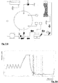
Fig. 4B is a schematic view similar to that ofFig. 2 , in an operational state corresponding to the cycle portion highlighted in the respectiveFig. 4A ; and -
Figs. 5A-7B are views similar to the homologous ones ofFig. 4A and 4B , of successive phases of steam injection and emptying of the sterilization chamber. - The scheme of
Fig. 2 shows the main component of an autoclave, which is taken as an exemplary scheme of a steam sterilization system. - A
sterilization chamber 1 is in the form of a sealingly closable container, able to withstand the sterilization pressure, generally cylindrical in shape.Chamber 1 is generally heated by various systems. - Fittings are provided on the wall of the
container 1 to connect the interior of thechamber 1 to a series of operating devices. In particular, thecontainer 1 is provided, at least, with aninlet connector 1a and with discharge means 1b. Theinlet connector 1a is intended to be connected to asteam generator 2, through therelated pipe 1a' and a controlledinlet valve 2a, from which it receives sterilization steam. The discharge means 1b are intended to be connected to acondenser 3, through therelated pipe 1b' and controlleddischarge valve 3a, in which the steam coming out from the sterilization chamber is typically condensed. - In the embodiment described in
Fig 2 , theinlet 2a anddischarge valves 3a are in the form of two separate three-way electrovalves. In this case, aloading inlet 2b connects thegenerator 2 to afirst port 2a 1 of theinlet valve 2a, then ajunction pipe 2c is provided which connects asecond port 2a 2 of thevalve 2a to asecond port 3avalve 3a and, finally, adischarge pipe 3b is provided which connects afirst port 3a1 of thevalve 3a to thecondenser 3. The twovalves pipes 1a' and 1b' through the respectivethird ports - However, it is not excluded that the flow control between
chamber 1,generator 2 andcondenser 3 can be managed differently; for example, theinlet 2a anddischarge valve 3a could be integrated into a single, more complex, controlled valve. - What is relevant for the purposes of the invention is the provision of a valve system which allows to alternately connect and isolate the
sterilization chamber 1 and thecondenser 3 with thegenerator 2. - On the wall of the
chamber 1 avent connector 1c is also provided for the connection to anair intake 4, provided with a suitable filter, suitable to allow ambient air to flow into the chamber, to rebalance the pressure before opening the autoclave. Along aconnection pipe 1c' between thevent connector 1c and theair intake 4, a controlledvent valve 4a is provided. - Finally, the
sterilization chamber 1 can have connectors to a pressure sensor, a safety overpressure valve, a temperature sensor and more. - The
condenser 3 is also connected to a first tank S1 of the waste used water through adischarge valve 3c, preferably a check valve or a non-return valve with automatic operation. In other words, thedischarge valve 3c places thecondenser 3 in communication with the ambient pressure and, when it is closed, it isolates the condenser from the external environment. A second tank S2 of clean water is connected to awater pump 5. The latter is controlled so as to inject water into thesteam generator 2 as required. - According to the invention it is possible to reach emptying levels of the
sterilization chamber 1 equal to or higher than those obtainable by using mechanical vacuum production systems, such as, for example, vacuum pumps. - With an original arrangement of the related connections between
chamber 1,steam generator 2 andcondenser 3, and by using a suitable operating mode of the valves, it becomes possible to exploit the steam condensation in thecondenser 3 to produce a thermodynamic effect of evacuation of the sterilization chamber. - In fact, according to the invention, an arrangement is provided in which the
steam generator 2 can be connected directly (i.e. without any other equipment having a thermodynamic effect on steam) to thecondenser 3 to introduce steam. The condenser is isolated from the external environment by means of thedischarge valve 3c, so that the cooling of the steam inside it results in a reduction in pressure of the circuit including the condenser which can be used to empty thesterilization chamber 1 when the latter is placed in communication with thecondenser 3. The pressure reduction in thecondenser 3, when thedischarge valve 3c is closed, can preferably be achieved (but it is not the only possible mode) by completely separating/isolating thecondenser 3 also from thesterilization chamber 1 and from thegenerator 2, by means of appropriate valves. - The steam condensation causes a pressure and volume reduction thereof in the
condenser 3 andchamber 1 system, suitably isolated from theelectrovalves chamber 1 andcondenser 3 which stops when the system has reached the pressure equilibrium. According to the invention, this flow is cyclically restarted, allowing to reach ever lower pressure levels (which correspond to higher emptying levels of the sterilization chamber 1). - It is therefore relevant for the purposes of the invention, that the connections and the valves are arranged to be able to isolate
chamber 1,generator 2 andcondenser 3 between them in specific phases of the process and therefore establish low pressure cycles in thecondenser 3 which allow to evacuate thesterilization chamber 1 without resorting to a mechanical pump. - To better understand this operating mode, reference is now made to the embodiment illustrated in
Fig. 3 and following. -
Fig. 3 shows a graph representing the pressure with respect to time within thesterilization chamber 1, during an exemplary process of the invention. As a non-limiting example, a preliminary phase is provided with a preheating step PHE and an air evacuation step PG obtained with pressure pulses in thesterilization chamber 1. Then there is an actual sterilization cycle, with a first step PPH of temperature (for example up to 145°C) and pressure (for example up to 3 bar) increase and then the maintenance of a plateau condition PR for the time necessary to complete the sterilization. - Then the actual emptying and drying DRY cycle takes place, in which the original sequence of the invention is effectively applied. The latter is analyzed in greater detail in some of its phases in
Figures 4A-7B . - In the first phase of the emptying and drying cycle (
Fig. 4A ) the greatest pressure drop occurs. Thechamber 1 is isolated from the generator 2 (valve 2a placed in position 1-2, i.e. communication between theports valve 3a placed in position 1-3), connected in turn to the discharge towards the first waste water tank S1 (seeFig. 4B ). The residual high pressure (e.g. 3 barA) inchamber 1, tends to quickly balance with the ambient pressure existing in thecondenser 3. - In the meantime, keeping the steam generator isolated from the sterilization chamber 1 - to prevent other steam from ending up in chamber 1 (which is drying) - it is possible to generate a small water injection into the steam generator, to produce and increase the steam pressure inside it (
Fig. 5B ) in preparation for the next operation step. - Subsequently (
Fig. 6B ) thechamber 1 is completely isolated - which thus stabilizes inside pressure (Fig. 6A ) - and thesteam generator 2 is put in communication with the condenser (valve 3a placed in position 1-2). The steam generated in thegenerator 2 enters thecondenser 3 and partially exits through thevalve 3c, pushing out condensate from the condenser. - Then (
Fig. 7B ) thevalve 3a is switched so as to put thesterilization chamber 1 in communication with thecondenser 3, possibly also isolating thegenerator 2 through thevalve 2a. As the condenser begins to cool the steam, there is a reduction in volume and therefore in pressure (Fig. 7A ); thevalve 3c is closed (or closes automatically if it is in the form of a check valve) and while the steam cools and condenses, the circuit including the condenser begins to go at low pressure. The pressure inside thecondenser 3 stabilizes at a value lower than the ambient atmospheric pressure and the existing one in thesterilization chamber 1, thus producing a progressive emptying of the latter. - Subsequently the same process can be repeated until the desired emptying of the sterilization chamber has been achieved.
- In brief, the method of the invention provides for injecting steam directly from the
generator 2 to the condenser 3 - i.e. a device designed for cooling and condensing the steam up to the liquid state - in which, due to the cooling of the steam in the gaseous state, it is possible to determine a reduction in the volume of the fluid and therefore a lowering of pressure: once it is placed in communication with the sterilization chamber, it acts as a point of low pressure for the emptying and drying of the sterilization chamber. - The steam injection into the condenser can be carried out at different stages of the sterilization cycle, preferably in a phase in which the
sterilization chamber 1 is isolated both from thegenerator 2 and from thecondenser 3. - As can be understood from the above description, through the configuration and the operation method of the invention, it is possible to fully achieve the purposes stated in the introduction.
- In fact, even without the presence of a vacuum pump, by performing a series of thermodynamic cycles of steam condensation - putting the
generator 2 in communication with thecondenser 3 when thechamber 1 is isolated - it is possible to obtain an effective emptying and drying inside the sterilization chamber. This allows to greatly reduce the economic and technological problems related to the operation of a mechanical pump. - It is however understood that the invention is not limited to the particular configuration illustrated above, which represents only a non-limiting example of its scope, but that numerous variants are possible, all within the reach of a skilled in the art, without thereby departing from the scope of the invention itself.
- For example, in the embodiment described in detail above, it is not foreseen to carry out an initial cycle of suction emptying of the sterilization chamber. Nothing prevents, however, to apply the principles taught with the invention, to obtain a thermodynamic emptying cycle even in any phase before the sterilization phase, for example immediately after closing the autoclave to eliminate the air inside the chamber (air that has insulating properties and makes the action of steam on the devices to be sterilized less effective - especially if they are porous or with internal cavities).
- Furthermore, although the two
inlet 2a anddischarge valves 3a have been illustrated connected to each other - then with a circuit which provides for a passage of steam from thegenerator 2 to thecondenser 3 through both valves - a similar principle operation can also be obtained with theinlet valve 2a connected directly to thechamber 1 and to thecondenser 3, without connection between the twovalves chamber 1 and the condenser 3: therefore it is more appropriate to indicate that an injection valve must be provided between the generator and the condenser which, in the illustrated embodiment, coincides with the inlet valve which also acts against the sterilization chamber. - In other words, the teaching of the invention can also be exploited in systems in which, for example:
- the hydraulic circuit has a connection between the steam generator and the condenser, without this connection passing through the sterilization chamber;
- the hydraulic circuit provides that the water injection carried out in the steam generator takes place with direct and/or indirect communication towards the condenser;
- the hydraulic circuit has one or more connections between one or more steam generators and one or more condensers, without these connections having to pass through the sterilization chamber.
- Finally, it is not entirely excluded to use a small vacuum pump, for example of low capacity and reduced cost, in addition to the thermodynamic vacuum process, in cases where it is appropriate to accelerate timing or to obtain a high vacuum (e.g. in a final phase, in which there is no longer the risk that the pump can suck in condensed fluid).
Claims (12)
- Sterilization method in a sterilization apparatus, in which at least an evacuation step of at least a sterilization chamber (1) is provided, in which a gaseous content of said chamber (1) is made to pass through at least a condenser (3), characterized in that the following evacuation cycle is performed one or more times,- said chamber (1) is isolated from said condenser (3),- at least a steam generator (2) is operated to inject a predetermined amount of heated steam directly into said condenser (3),- said steam in the condenser (3) is cooled and condensed, so as to reduce its volume and accordingly lower the pressure within said condenser (3) to below that present in said sterilization chamber,- said condenser (3) is placed in communication with said sterilization chamber (1) to perform an evacuation.
- Sterilization method as in 1, wherein a valve (3c) is provided between said condenser (3) and a drain tank (S1) to isolate said condenser (3) from the drain tank (S1) during said cooling step.
- Sterilization method as in claim 1, wherein said discharge valve (3c) is apt to isolate said condenser (3) from the drain tank (S1) in a condition where a controlled inlet valve (2a) between said steam generator (2) and the chamber (1) is closed.
- Sterilization method as in any one of the preceding claims, wherein said steam generator (2) is also connectable to said sterilization chamber (1) and said cooling and condensation step of the steam in the condenser (3) is carried out by isolating said steam generator (2) from the chamber (1) and from the condenser (3).
- Sterilization method as in any one of the preceding claims, wherein said step of injecting steam into said condenser (3) results in expulsion of condensate present in the condenser (3) .
- Sterilization method as in any one of the preceding claims, wherein said evacuation cycle is performed in a final drying step.
- Sterilization method as in any one of the preceding claims, wherein said evacuation cycle is performed at an early stage to evacuate air and/or any fluids from the inside of said chamber (1).
- Sterilization system for performing a sterilization cycle, comprising
at least an airtight sterilization chamber (1), adapted to contain a load on which a sterilization cycle is performed,
at least one steam generator (2) in fluid communication with said at least a chamber (1) by means of at least a controlled inlet valve (2a),
at least a condenser (3), in fluid communication with said at least a chamber (1) by means of at least a controlled outlet valve (3a), apt to cool and condense steam from said sterilization chamber (1),
characterized in that said at least a steam generator (2) is also connected to said at least a condenser (3) through a controlled injection valve to generate and input steam directly into said condenser (3) in a condition where said at least a controlled outlet valve (3a) is closed so that the sterilization chamber (1) is isolated at least from said generator (2). - Autoclave as in claim 8, in which a discharge valve (3c) is arranged downstream of said at least a condenser (3) with respect to the steam generator (2) to discharge condensate and/or steam towards a collection tank (S1).
- Autoclave as in claim 9, wherein said discharge valve (3c) is provided between said condenser (3) and said drain tank (S1) to isolate said condenser (3) from the drain tank (S1).
- Autoclave as in claim 8, 9 or 10, wherein said controlled injection valve and said controlled outlet valve (3a) are independent and connected in fluid communication to each other (2c).
- Autoclave as in claim 11, wherein said controlled injection valve coincides with said controlled inlet valve (2a).
Applications Claiming Priority (1)
| Application Number | Priority Date | Filing Date | Title |
|---|---|---|---|
| IT102016000131201A IT201600131201A1 (en) | 2016-12-27 | 2016-12-27 | PERFORMED THERMODYNAMIC CYCLE STERILIZATION SYSTEM AND RELATED METHOD |
Publications (2)
| Publication Number | Publication Date |
|---|---|
| EP3342429A1 true EP3342429A1 (en) | 2018-07-04 |
| EP3342429B1 EP3342429B1 (en) | 2023-09-06 |
Family
ID=58670234
Family Applications (1)
| Application Number | Title | Priority Date | Filing Date |
|---|---|---|---|
| EP17210371.5A Active EP3342429B1 (en) | 2016-12-27 | 2017-12-22 | Sterilization system and method having a thermodynamic cycle |
Country Status (5)
| Country | Link |
|---|---|
| US (1) | US10772978B2 (en) |
| EP (1) | EP3342429B1 (en) |
| ES (1) | ES2963220T3 (en) |
| IT (1) | IT201600131201A1 (en) |
| PL (1) | PL3342429T3 (en) |
Cited By (2)
| Publication number | Priority date | Publication date | Assignee | Title |
|---|---|---|---|---|
| DE202022106798U1 (en) | 2021-12-06 | 2023-03-09 | Cefla Societa' Cooperativa | autoclave |
| EP4190365A1 (en) | 2021-12-06 | 2023-06-07 | Cefla Societa' Cooperativa | Autoclave |
Citations (5)
| Publication number | Priority date | Publication date | Assignee | Title |
|---|---|---|---|---|
| GB993883A (en) * | 1961-03-04 | 1965-06-02 | Electrolux Ab | Improvements in sterilisation autoclaves |
| EP0852146A2 (en) * | 1997-01-03 | 1998-07-08 | Spiridon Markatis | Sterilisation and disunfection without secondary infection |
| EP0992247A1 (en) * | 1998-10-05 | 2000-04-12 | Dentalwerk Bürmoos Gesellschaft M.B.H. | Autoclave |
| EP1175231A1 (en) * | 1999-04-06 | 2002-01-30 | Scican, a division of Lux and Zwingenberger Ltd. | Sterilizer with vacuum-assisted air removal |
| DE102012010739A1 (en) * | 2011-06-29 | 2013-05-16 | DüRR DENTAL AG | Condenser for steam sterilizer, has condensate outlet and gas outlet that are provided at lower end wall, and are connected with suction pump through respective valves |
Family Cites Families (2)
| Publication number | Priority date | Publication date | Assignee | Title |
|---|---|---|---|---|
| SE312199B (en) | 1965-09-27 | 1969-07-07 | Electrolux Ab | |
| GB2316463B (en) | 1996-08-15 | 2000-07-05 | Honeywell Control Syst | Flow control |
-
2016
- 2016-12-27 IT IT102016000131201A patent/IT201600131201A1/en unknown
-
2017
- 2017-12-22 EP EP17210371.5A patent/EP3342429B1/en active Active
- 2017-12-22 PL PL17210371.5T patent/PL3342429T3/en unknown
- 2017-12-22 ES ES17210371T patent/ES2963220T3/en active Active
- 2017-12-27 US US15/855,582 patent/US10772978B2/en active Active
Patent Citations (5)
| Publication number | Priority date | Publication date | Assignee | Title |
|---|---|---|---|---|
| GB993883A (en) * | 1961-03-04 | 1965-06-02 | Electrolux Ab | Improvements in sterilisation autoclaves |
| EP0852146A2 (en) * | 1997-01-03 | 1998-07-08 | Spiridon Markatis | Sterilisation and disunfection without secondary infection |
| EP0992247A1 (en) * | 1998-10-05 | 2000-04-12 | Dentalwerk Bürmoos Gesellschaft M.B.H. | Autoclave |
| EP1175231A1 (en) * | 1999-04-06 | 2002-01-30 | Scican, a division of Lux and Zwingenberger Ltd. | Sterilizer with vacuum-assisted air removal |
| DE102012010739A1 (en) * | 2011-06-29 | 2013-05-16 | DüRR DENTAL AG | Condenser for steam sterilizer, has condensate outlet and gas outlet that are provided at lower end wall, and are connected with suction pump through respective valves |
Cited By (3)
| Publication number | Priority date | Publication date | Assignee | Title |
|---|---|---|---|---|
| DE202022106798U1 (en) | 2021-12-06 | 2023-03-09 | Cefla Societa' Cooperativa | autoclave |
| IT202100030749A1 (en) | 2021-12-06 | 2023-06-06 | Cefla Soc Cooperativa | AUTOCLAVE |
| EP4190365A1 (en) | 2021-12-06 | 2023-06-07 | Cefla Societa' Cooperativa | Autoclave |
Also Published As
| Publication number | Publication date |
|---|---|
| ES2963220T3 (en) | 2024-03-26 |
| US10772978B2 (en) | 2020-09-15 |
| US20180177903A1 (en) | 2018-06-28 |
| EP3342429B1 (en) | 2023-09-06 |
| IT201600131201A1 (en) | 2018-06-27 |
| PL3342429T3 (en) | 2024-02-26 |
Similar Documents
| Publication | Publication Date | Title |
|---|---|---|
| AU758173B2 (en) | Autoclave | |
| EP3342429B1 (en) | Sterilization system and method having a thermodynamic cycle | |
| CN103394106A (en) | Steam sterilizer and sterilization process | |
| CN104083781B (en) | A kind of sterilizing methods of steam autoclave and steam autoclave | |
| CN104081063A (en) | Steam sterilization device | |
| JPH08505786A (en) | Freeze dryer decontamination method | |
| CN109028771A (en) | Double cabin vacuum shelf dryers and the method being dried using it | |
| RU2017113485A (en) | Device and method for detecting moisture in a vacuum chamber | |
| RU2017116166A (en) | Device and method for detecting moisture in a vacuum chamber | |
| CN109028772A (en) | Water-cycle heating and drying cupboard | |
| CN203417350U (en) | Steam disinfector | |
| CZ20022044A3 (en) | Autoclave | |
| JP2010519979A (en) | Sterilizer, sterilization method, evaporation system and method of using such an evaporation system | |
| CN110507173A (en) | Cooking apparatus and its control method, control device and computer readable storage medium | |
| CN104548158B (en) | High/low temperature sterilizing cabinet | |
| JP6748456B2 (en) | Vacuum cooling device | |
| EP0848958A2 (en) | Autoclaves and methods of manufacture | |
| US20180347902A1 (en) | Method and system for drying an enclosure | |
| CN114588285A (en) | Sterilization method | |
| CN111989529B (en) | Apparatus and method for selective shelf temperature control | |
| CN105148301A (en) | Constant-temperature and constant-humidity device for storing medicinal materials | |
| CN204100715U (en) | Vacuum drying chamber | |
| CN111035775B (en) | Integrated steam pipeline discharge system for sterilization room and control method thereof | |
| EP4190365A1 (en) | Autoclave | |
| JP4590140B2 (en) | High-pressure steam sterilizer and high-pressure steam sterilization method |
Legal Events
| Date | Code | Title | Description |
|---|---|---|---|
| PUAI | Public reference made under article 153(3) epc to a published international application that has entered the european phase |
Free format text: ORIGINAL CODE: 0009012 |
|
| STAA | Information on the status of an ep patent application or granted ep patent |
Free format text: STATUS: THE APPLICATION HAS BEEN PUBLISHED |
|
| AK | Designated contracting states |
Kind code of ref document: A1 Designated state(s): AL AT BE BG CH CY CZ DE DK EE ES FI FR GB GR HR HU IE IS IT LI LT LU LV MC MK MT NL NO PL PT RO RS SE SI SK SM TR |
|
| AX | Request for extension of the european patent |
Extension state: BA ME |
|
| STAA | Information on the status of an ep patent application or granted ep patent |
Free format text: STATUS: REQUEST FOR EXAMINATION WAS MADE |
|
| 17P | Request for examination filed |
Effective date: 20181221 |
|
| RBV | Designated contracting states (corrected) |
Designated state(s): AL AT BE BG CH CY CZ DE DK EE ES FI FR GB GR HR HU IE IS IT LI LT LU LV MC MK MT NL NO PL PT RO RS SE SI SK SM TR |
|
| STAA | Information on the status of an ep patent application or granted ep patent |
Free format text: STATUS: REQUEST FOR EXAMINATION WAS MADE |
|
| STAA | Information on the status of an ep patent application or granted ep patent |
Free format text: STATUS: EXAMINATION IS IN PROGRESS |
|
| 17Q | First examination report despatched |
Effective date: 20210622 |
|
| STAA | Information on the status of an ep patent application or granted ep patent |
Free format text: STATUS: EXAMINATION IS IN PROGRESS |
|
| 17Q | First examination report despatched |
Effective date: 20210728 |
|
| GRAP | Despatch of communication of intention to grant a patent |
Free format text: ORIGINAL CODE: EPIDOSNIGR1 |
|
| STAA | Information on the status of an ep patent application or granted ep patent |
Free format text: STATUS: GRANT OF PATENT IS INTENDED |
|
| INTG | Intention to grant announced |
Effective date: 20230502 |
|
| GRAS | Grant fee paid |
Free format text: ORIGINAL CODE: EPIDOSNIGR3 |
|
| GRAA | (expected) grant |
Free format text: ORIGINAL CODE: 0009210 |
|
| STAA | Information on the status of an ep patent application or granted ep patent |
Free format text: STATUS: THE PATENT HAS BEEN GRANTED |
|
| AK | Designated contracting states |
Kind code of ref document: B1 Designated state(s): AL AT BE BG CH CY CZ DE DK EE ES FI FR GB GR HR HU IE IS IT LI LT LU LV MC MK MT NL NO PL PT RO RS SE SI SK SM TR |
|
| REG | Reference to a national code |
Ref country code: GB Ref legal event code: FG4D |
|
| REG | Reference to a national code |
Ref country code: CH Ref legal event code: EP |
|
| REG | Reference to a national code |
Ref country code: IE Ref legal event code: FG4D |
|
| REG | Reference to a national code |
Ref country code: DE Ref legal event code: R096 Ref document number: 602017073720 Country of ref document: DE |
|
| P01 | Opt-out of the competence of the unified patent court (upc) registered |
Effective date: 20230830 |
|
| REG | Reference to a national code |
Ref country code: RO Ref legal event code: EPE |
|
| REG | Reference to a national code |
Ref country code: NL Ref legal event code: FP |
|
| REG | Reference to a national code |
Ref country code: SE Ref legal event code: TRGR |
|
| REG | Reference to a national code |
Ref country code: LT Ref legal event code: MG9D |
|
| PGFP | Annual fee paid to national office [announced via postgrant information from national office to epo] |
Ref country code: NL Payment date: 20231121 Year of fee payment: 7 |
|
| PG25 | Lapsed in a contracting state [announced via postgrant information from national office to epo] |
Ref country code: GR Free format text: LAPSE BECAUSE OF FAILURE TO SUBMIT A TRANSLATION OF THE DESCRIPTION OR TO PAY THE FEE WITHIN THE PRESCRIBED TIME-LIMIT Effective date: 20231207 |
|
| PGFP | Annual fee paid to national office [announced via postgrant information from national office to epo] |
Ref country code: GB Payment date: 20231030 Year of fee payment: 7 |
|
| PG25 | Lapsed in a contracting state [announced via postgrant information from national office to epo] |
Ref country code: RS Free format text: LAPSE BECAUSE OF FAILURE TO SUBMIT A TRANSLATION OF THE DESCRIPTION OR TO PAY THE FEE WITHIN THE PRESCRIBED TIME-LIMIT Effective date: 20230906 Ref country code: NO Free format text: LAPSE BECAUSE OF FAILURE TO SUBMIT A TRANSLATION OF THE DESCRIPTION OR TO PAY THE FEE WITHIN THE PRESCRIBED TIME-LIMIT Effective date: 20231206 Ref country code: LV Free format text: LAPSE BECAUSE OF FAILURE TO SUBMIT A TRANSLATION OF THE DESCRIPTION OR TO PAY THE FEE WITHIN THE PRESCRIBED TIME-LIMIT Effective date: 20230906 Ref country code: LT Free format text: LAPSE BECAUSE OF FAILURE TO SUBMIT A TRANSLATION OF THE DESCRIPTION OR TO PAY THE FEE WITHIN THE PRESCRIBED TIME-LIMIT Effective date: 20230906 Ref country code: HR Free format text: LAPSE BECAUSE OF FAILURE TO SUBMIT A TRANSLATION OF THE DESCRIPTION OR TO PAY THE FEE WITHIN THE PRESCRIBED TIME-LIMIT Effective date: 20230906 Ref country code: GR Free format text: LAPSE BECAUSE OF FAILURE TO SUBMIT A TRANSLATION OF THE DESCRIPTION OR TO PAY THE FEE WITHIN THE PRESCRIBED TIME-LIMIT Effective date: 20231207 Ref country code: FI Free format text: LAPSE BECAUSE OF FAILURE TO SUBMIT A TRANSLATION OF THE DESCRIPTION OR TO PAY THE FEE WITHIN THE PRESCRIBED TIME-LIMIT Effective date: 20230906 |
|
| PGFP | Annual fee paid to national office [announced via postgrant information from national office to epo] |
Ref country code: RO Payment date: 20231123 Year of fee payment: 7 Ref country code: IT Payment date: 20231115 Year of fee payment: 7 Ref country code: FR Payment date: 20231030 Year of fee payment: 7 Ref country code: DE Payment date: 20231030 Year of fee payment: 7 Ref country code: AT Payment date: 20231201 Year of fee payment: 7 |
|
| REG | Reference to a national code |
Ref country code: ES Ref legal event code: FG2A Ref document number: 2963220 Country of ref document: ES Kind code of ref document: T3 Effective date: 20240326 |
|
| PG25 | Lapsed in a contracting state [announced via postgrant information from national office to epo] |
Ref country code: IS Free format text: LAPSE BECAUSE OF FAILURE TO SUBMIT A TRANSLATION OF THE DESCRIPTION OR TO PAY THE FEE WITHIN THE PRESCRIBED TIME-LIMIT Effective date: 20240106 |
|
| PGFP | Annual fee paid to national office [announced via postgrant information from national office to epo] |
Ref country code: ES Payment date: 20240116 Year of fee payment: 7 |