EP3342015B1 - Prefabricated sleeve body for connecting two high-voltage polymer cables for direct current - Google Patents
Prefabricated sleeve body for connecting two high-voltage polymer cables for direct current Download PDFInfo
- Publication number
- EP3342015B1 EP3342015B1 EP16720035.1A EP16720035A EP3342015B1 EP 3342015 B1 EP3342015 B1 EP 3342015B1 EP 16720035 A EP16720035 A EP 16720035A EP 3342015 B1 EP3342015 B1 EP 3342015B1
- Authority
- EP
- European Patent Office
- Prior art keywords
- sleeve body
- insulation material
- insulation
- ωcm
- deflector
- Prior art date
- Legal status (The legal status is an assumption and is not a legal conclusion. Google has not performed a legal analysis and makes no representation as to the accuracy of the status listed.)
- Active
Links
- 229920000642 polymer Polymers 0.000 title description 5
- 239000012774 insulation material Substances 0.000 claims description 39
- 238000009413 insulation Methods 0.000 claims description 11
- 229920001971 elastomer Polymers 0.000 claims description 8
- 239000000806 elastomer Substances 0.000 claims description 8
- 239000011810 insulating material Substances 0.000 claims description 6
- 229920000181 Ethylene propylene rubber Polymers 0.000 claims description 4
- 229920002379 silicone rubber Polymers 0.000 claims description 4
- 229920002943 EPDM rubber Polymers 0.000 claims description 3
- 230000005684 electric field Effects 0.000 description 18
- 239000000463 material Substances 0.000 description 14
- 238000009826 distribution Methods 0.000 description 7
- XLOMVQKBTHCTTD-UHFFFAOYSA-N Zinc monoxide Chemical compound [Zn]=O XLOMVQKBTHCTTD-UHFFFAOYSA-N 0.000 description 2
- 239000006229 carbon black Substances 0.000 description 2
- 230000015556 catabolic process Effects 0.000 description 2
- 229920003020 cross-linked polyethylene Polymers 0.000 description 2
- 239000004703 cross-linked polyethylene Substances 0.000 description 2
- 239000000945 filler Substances 0.000 description 2
- 238000000034 method Methods 0.000 description 2
- 238000013329 compounding Methods 0.000 description 1
- 238000010276 construction Methods 0.000 description 1
- 230000001419 dependent effect Effects 0.000 description 1
- 229920001296 polysiloxane Polymers 0.000 description 1
- 238000004088 simulation Methods 0.000 description 1
- 238000009827 uniform distribution Methods 0.000 description 1
- 239000011787 zinc oxide Substances 0.000 description 1
Images
Classifications
-
- H—ELECTRICITY
- H02—GENERATION; CONVERSION OR DISTRIBUTION OF ELECTRIC POWER
- H02G—INSTALLATION OF ELECTRIC CABLES OR LINES, OR OF COMBINED OPTICAL AND ELECTRIC CABLES OR LINES
- H02G15/00—Cable fittings
- H02G15/08—Cable junctions
- H02G15/10—Cable junctions protected by boxes, e.g. by distribution, connection or junction boxes
- H02G15/103—Cable junctions protected by boxes, e.g. by distribution, connection or junction boxes with devices for relieving electrical stress
Definitions
- the insulation of the sleeve body consists of at least two insulating elastomers, these elastomers differing in their electrical properties and the insulation materials are arranged in the sleeve body in a certain way.
- the insulating elastomers can consist of the same base material, such as a silicone elastomer.
- the different electrical properties can be achieved by adding different fillers such as carbon black.
- the base materials of the insulating elastomers can also be different. So z. B. one insulation material consist of an EPR or EPDM, while the other can consist of a silicone elastomer.
- the electrical field distribution when several insulating materials are combined depends on the specific electrical resistance of the materials involved.
- the field distribution in two different materials is generally given by the ratio of the specific resistances of the materials involved.
- the insulating materials involved are the cable insulation, which usually consists of a cross-linked polyethylene (XLPE) and the insulation of the sleeve body, which usually consists of an elastomer such as a silicone or an EPR.
- the suitable arrangement of the two insulation materials in the sleeve body can ensure that the electrical field distribution is relatively even under direct voltage stress and that the electrical strength under surge voltage stress is high enough so that there is no breakdown within the sleeve body.
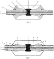
- Figure 1 an arrangement of the two insulation materials in an HVDC sleeve body is illustrated.
- the first insulation material (5) has a lower specific electrical resistance than the second insulation material (8) in a temperature range typically between 0 ° C. and 70 ° C. Since the specific electrical resistance can depend on the electrical field strength at which it was measured, the specific electrical resistances are to be determined for several electrical field strengths in a range of typically 2 kV / mm to 30 kV / mm.
- the arrangement of the first insulation material (5) is important for the functioning of the sleeve. Since high electrical fields occur between the deflector (4), which is at ground potential, and the center electrode (7), which is at high voltage potential, the first insulation material (5) must form a continuous connection between the deflector and the center electrode. An interruption in the connection would lead to an excessive field strength in the second insulation material with the higher specific electrical resistance.
- Another important feature in the construction of the sleeve body is that there is no interface between the two insulation materials between the deflector and the cable insulation. Since interfaces generally represent weak points with regard to dielectric strength and the electrical field strength is very high in the case of surge voltages between the deflector and the cable insulation, no interface between the two insulation materials should run in the sleeve body in this area.
- Socket bodies of the generic type which are suitable for high-voltage cables for direct voltage, are from the WO 2013/004748 A2 and the FR2 498 022 A1 known, the latter disclosing the preamble of claim 1.
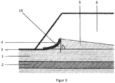
- the present invention circumvents this problem, since there is no interface in the area that is electrically critical in the case of surge voltages (see Sect. Figure 3 ) comes to rest.
- This electrically critical area within the sleeve body is limited on the one hand by the deflector and on the other hand by an imaginary plane which runs perpendicular to the sleeve axis through the tip of the deflector.
- the specific electrical resistances of the selected insulation materials and their temperature dependencies are important for the functioning of the illustrated invention. Since the electrical resistances of insulation materials generally also depend on the electrical field strength, the electrical field strength at which these electrical resistances were measured must also be specified when specifying the volume resistances. The following specifications of the specific electrical resistances relate to an electrical field strength of 10 kV / mm.
- the specific electrical resistance of the first insulation material (5) with the lower electrical resistance should be between 10 10 ⁇ cm and 10 16 ⁇ cm at room temperature and between 10 9 ⁇ cm and 10 15 ⁇ cm at 70 ° C.
- the specific electrical resistance of the second insulation material (8) with the higher electrical resistance should be between 10 12 ⁇ cm and 10 17 ⁇ cm at room temperature.
- the volume resistance of this material should be between 10 11 ⁇ cm and 10 16 ⁇ cm.
- the difference between the specific electrical resistances of the insulation materials in the socket body must be at least a factor of 2 and a maximum of a factor of 1000 both at room temperature and at 70 ° C and the specified field strength of 10 kV / mm.
- the first insulation material (5) and / or the second insulation material (8) consists of an ethylene-propylene rubber or an ethylene-propylene-diene rubber or a silicone elastomer.
- insulating elastomers has the advantage that different electrical properties of the first and / or second insulation material can be achieved in a simple manner by adding different fillers, such as carbon black, using a compounding process known to the person skilled in the art.
Description
Gegenstand der Erfindung gemäss den aufgeführten Ansprüchen ist eine Muffe für die Verbindung von Hochspannungspolymerkabeln für Gleichstrom (HVDC Polymerkabel). Kennzeichnend für die Erfindung ist, dass die Isolierung des Muffenkörpers aus mindestens zwei isolierenden Elastomeren besteht, wobei sich diese Elastomere in ihren elektrischen Eigenschaften unterscheiden und die Isolationsmaterialien auf bestimmte Weise in dem Muffenkörper angeordnet sind. Die isolierenden Elastomere können aus dem gleichen Basismaterial, wie z.B. einem Silikonelastomer, bestehen. Die unterschiedlichen elektrischen Eigenschaften können durch die unterschiedliche Zugabe von Füllstoffen, wie z.B. Russ, erzielt werden. Die Basismaterialien der isolierenden Elastomere können aber auch unterschiedlich sein. So kann z. B. das eine Isolationsmaterial aus einem EPR oder EPDM bestehen, während das andere aus einem Silikonelastomer bestehen kann.The subject of the invention according to the cited claims is a sleeve for the connection of high-voltage polymer cables for direct current (HVDC polymer cables). It is characteristic of the invention that the insulation of the sleeve body consists of at least two insulating elastomers, these elastomers differing in their electrical properties and the insulation materials are arranged in the sleeve body in a certain way. The insulating elastomers can consist of the same base material, such as a silicone elastomer. The different electrical properties can be achieved by adding different fillers such as carbon black. However, the base materials of the insulating elastomers can also be different. So z. B. one insulation material consist of an EPR or EPDM, while the other can consist of a silicone elastomer.
Bei Gleichspannung hängt die elektrische Feldverteilung bei der Kombination von mehreren isolierenden Materialien von dem spezifischen elektrischen Widerstand der beteiligten Materialien ab. Dabei ist die Feldverteilung in zwei verschiedenen Materialien im Allgemeinen durch das Verhältnis der spezifischen Widerstände der beteiligten Materialien gegeben. In Muffen für HVDC Polymerkabel sind die beteiligten Isolierstoffe die Kabelisolation, welche in der Regel aus einem vernetzten Polyethylen (XLPE) besteht und der Isolation des Muffenkörpers, die in der Regel aus einem Elastomer, wie z.B. einem Silikon oder einem EPR besteht. Da die spezifischen elektrischen Widerstände dieser Materialien sich mit der Temperatur verändern und diese Temperaturabhängigkeit der spezifischen Widerstände von den jeweiligen Materialien abhängig ist, ist es sehr schwierig, einen Isolierstoff für einen Muffenkörper zu finden, der in einem grossen Temperaturbereich eine gleichmässige Verteilung des elektrischen Feldes in dem Muffenkörper gewährleistet. Mit der vorliegenden Erfindung wird dieses Problem deutlich reduziert. Mit der Kombination von mindestens zwei isolierenden Elastomeren mit unterschiedlichen elektrischen Eigenschaften in dem Muffenkörper wird erreicht, dass die elektrische Feldverteilung innerhalb des Muffenkörpers über einen grossen Temperaturbereich gleichmässiger wird, als dies im Allgemeinen mit nur einem Isolationsmaterial möglich wäre. Durch die geeignete Anordnung der beiden Isolationsmaterialien in dem Muffenkörper kann gewährleistet werden, dass die elektrische Feldverteilung unter Gleichspannungsbeanspruchung relativ gleichmässig ist und dass die elektrische Festigkeit unter Stossspannungsbeanspruchung gross genug ist, so dass es zu keinem Durchschlag innerhalb des Muffenkörpers kommt. In
Gattungsgemäße Muffenkörper, welche für Hochspannungskabel für Gleichspannung geeignet sind, sind aus der
Weiterer Stand der Technik zur Reduzierung der starken Temperaturabhängigkeit des elektrischen Feldes in einer Hochspannungsmuffe für Gleichspannungen und zur Erzielung einer gleichmässigen Feldverteilung ist die Verwendung von einem nichtlinearen resistiven Feldsteuermaterial zur Aussteuerung der elektrischen Felder in dem Muffenkörper, wie es z.B. in dem
In der erwähnten Publikation wird beschrieben, wie eine Schicht aus einem Feldsteuermaterial zwischen dem Erdpotenzial der halbleitenden Schicht des Kabels und dem Hochspannungspotenzial beim Kabelverbinder die Abhängigkeit der elektrischen Feldverteilung von dem Verhältnis der Widerstände der Kabelisolation und der Muffenisolation aufhebt. Ein Nachteil dieser Lösung ist allerdings, dass bei der zusätzlichen Verwendung eines Seitfähigen Deflektors in der Kabelmuffe, wie er z.B. zur Erfüllung der Stossspannungsanforderungen notwendig sein kann, die feldsteuernde Schicht und damit die Grenzfläche zwischen dem Feldsteuermaterial und dem Isolationsmaterial in Gebieten unterhalb des Deflektors zu liegen kommt, die bei Stossspannungsbeanspruchung hohen elektrischen Feldern ausgesetzt ist. Dies kann unter Umständen zu einem Durchschlag des Muffenkörpers führen. Mit der vorliegenden Erfindung wird diese Problematik umgangen, da keine Grenzfläche in dem bei Stossspannungen elektrisch kritischen Gebiet (s.
Wichtig für die Funktionsweise der dargestellten Erfindung sind die spezifischen elektrische Widerstände der ausgewählten Isolationsmaterialien und deren Temperaturabhängigkeiten. Da die elektrischen Widerstände von Isolationsmaterialien im Allgemeinen auch von der elektrischen Feldstärke abhängen, muss bei der Festlegung der Volumenwiderstände auch die elektrische Feldstärke, bei denen diese elektrischen Widerstände gemessen wurden, angegeben werden. Die folgenden Angaben der spezifischen elektrischen Widerstände beziehen sich auf eine elektrische Feldstärke von 10 kV/mm. Der spezifische elektrische Widerstand von dem ersten Isolationsmaterial (5) mit dem geringeren elektrischen Widerstand soll bei Raumtemperatur zwischen 1010 Qcm und 1016 Ωcm und bei 70°C zwischen 109 Qcm und 1015 Qcm liegen. Der spezifische elektrische Widerstand von dem zweiten Isolationsmaterial (8) mit dem höheren elektrischen Widerstand soll bei Raumtemperatur zwischen 1012 Qcm und 1017 Qcm liegen. Bei 70 °C soll der Volumenwiderstand dieses Materials zwischen 1011 Ωcm und 1016 Ωcm liegen. Der Unterschied zwischen den spezifischen elektrischen Widerständen der Isolationsmaterialen in dem Muffenkörper muss sowohl bei Raumtemperatur wie auch bei 70°C und der angegebenen Feldstärke von 10 kV/mm mindestens den Faktor 2 und maximal den Faktor 1000 betragen. Ein grösserer Unterschied in den spezifischen elektrischen Widerständen, z.B. ein Faktor zwischen 3 und 50, wird als Vorteil angesehen.The specific electrical resistances of the selected insulation materials and their temperature dependencies are important for the functioning of the illustrated invention. Since the electrical resistances of insulation materials generally also depend on the electrical field strength, the electrical field strength at which these electrical resistances were measured must also be specified when specifying the volume resistances. The following specifications of the specific electrical resistances relate to an electrical field strength of 10 kV / mm. The specific electrical resistance of the first insulation material (5) with the lower electrical resistance should be between 10 10 Ωcm and 10 16 Ωcm at room temperature and between 10 9 Ωcm and 10 15 Ωcm at 70 ° C. The specific electrical resistance of the second insulation material (8) with the higher electrical resistance should be between 10 12 Ωcm and 10 17 Ωcm at room temperature. At 70 ° C, the volume resistance of this material should be between 10 11 Ωcm and 10 16 Ωcm. The difference between the specific electrical resistances of the insulation materials in the socket body must be at least a factor of 2 and a maximum of a factor of 1000 both at room temperature and at 70 ° C and the specified field strength of 10 kV / mm. A larger difference in the specific electrical resistances, for example a factor between 3 and 50, is seen as an advantage.
In einer bevorzugten Ausführungsform des erfindungsgemässen Muffenkörpers besteht das erste Isolationsmaterial (5) und/oder das zweite Isolationsmaterial (8) aus einem Ethylen-Propylen Gummi oder aus einem Ethylen-Propylen-Dien Gummi oder aus einem Silikonelastomer.In a preferred embodiment of the socket body according to the invention, the first insulation material (5) and / or the second insulation material (8) consists of an ethylene-propylene rubber or an ethylene-propylene-diene rubber or a silicone elastomer.
Die Verwendung dieser isolierenden Elastomere bringt den Vorteil, dass durch Zugabe unterschiedlicher Füllstoffe, wie z.B. Russ, mittels einem dem Fachmann bekannten Compoundierverfahren in einfacher Art und Weise unterschiedliche elektrische Eigenschaften des ersten und/oder zweiten Isolationsmaterials erzielt werden können.The use of these insulating elastomers has the advantage that different electrical properties of the first and / or second insulation material can be achieved in a simple manner by adding different fillers, such as carbon black, using a compounding process known to the person skilled in the art.
-
Figur 1 : Schematische Darstellung eines Muffenkörpers auf zwei verbundenen Hochspannungskabeln mit integriertem Deflektor (4), integrierter Mittelelektrode (7) und zwei Isolationsmaterialien mit unterschiedlichen elektrischen Eigenschaften. Das erste Isolationsmaterial (5) mit dem geringeren spezifischen elektrischen Widerstand verbindet den Deflektor mit der Mittelelektrode und umhüllt den Deflektor.Figure 1 : Schematic representation of a joint body on two connected high-voltage cables with integrated deflector (4), integrated central electrode (7) and two insulation materials with different electrical properties. The first insulation material (5) with the lower specific electrical resistance connects the deflector to the center electrode and envelops the deflector. -
Figur 2 : Schematische Darstellung eines Muffenkörpers auf zwei verbundenen Hochspannungskabel, wobei das erste Isolationsmaterial (5) mit dem geringeren spezifischen elektrischen Widerstand den ganzen Bereich zwischen dem Deflektor (4) und der Kabelisolation (1) ausfüllt, so dass die beiden Isolationsmaterialien des Muffenkörpers in diesem kritischen Gebiet keine Grenzfläche bilden. Die äussere Oberfläche des Muffenkörpers ist mit einer elektrisch leitfähigen Schicht (9) bedeckt.Figure 2 : Schematic representation of a joint body on two connected high-voltage cables, whereby the first insulation material (5) with the lower specific electrical resistance fills the whole area between the deflector (4) and the cable insulation (1), so that the two insulating materials of the joint body are critical in this Area do not form an interface. The outer surface of the sleeve body is covered with an electrically conductive layer (9). -
Figur 3 : Schematische Darstellung des kritischen Bereichs (10) unterhalb des Deflektors, in dem keine Grenzfläche zwischen den beiden Isolationsmaterialien des Muffenkörpers bestehen soll. Das kritische Gebiet wird durch den Deflektor (4) und die gedachte Ebene, die senkrecht zur Muffenachse durch die Spitze des Deflektors verläuft, begrenzt.Figure 3 : Schematic representation of the critical area (10) below the deflector, in which there should be no interface between the two insulation materials of the sleeve body. The critical area is limited by the deflector (4) and the imaginary plane that runs perpendicular to the sleeve axis through the tip of the deflector.
Beschreibung der Abkürzungen in den Figuren:
- 1:
- Kabelisolation
- 2:
- Kabelleiter
- 3:
- Äussere halbleitende Schicht über der Kabelisolation
- 4:
- Deflektor
- 5:
- Erstes Isolationsmaterial in dem Muffenkörper
- 6:
- Verbinder der Kabelleiter
- 7:
- Mittelelektrode
- 8:
- Zweites Isolationsmaterial in dem Muffenkörper
- 9:
- Elektrisch leitfähige Schicht
- 10:
- Bezeichnung des elektrisch kritischen Gebietes innerhalb des Muffenkörpers, in dem keine Grenzfläche zwischen den Isolationsmaterialien des Muffenkörpers liegen soll
- 1:
- Cable insulation
- 2:
- Cable ladder
- 3:
- Outer semiconducting layer over the cable insulation
- 4:
- Deflector
- 5:
- First insulation material in the sleeve body
- 6:
- Connector of the cable ladder
- 7:
- Center electrode
- 8th:
- Second insulation material in the sleeve body
- 9:
- Electrically conductive layer
- 10:
- Designation of the electrically critical area within the joint body, in which there should be no interface between the insulating materials of the joint body
Claims (5)
- Sleeve body for the connection of polymeric high-voltage cables for direct voltages, consisting of two electrically conductive deflectors (4), a conductive center electrode (7) and an insulation of two different insulation materials, wherein the first and the second insulation material consist of elastomers, and wherein the first insulation material (5) continuously connects the respective deflector (4) to the center electrode (7), and wherein the insulation materials are arranged within the sleeve body in such a way that in the area, which is bounded by the respective deflector and an imaginary plane which runs perpendicular to the sleeve axis through the tip of the respective deflector, there is no interface between the first insulation material (5) and the second insulation material (8) within the sleeve body, characterized in that the specific electrical resistance of the first insulation material (5) at a field strength of 10 kV/mm at room temperature is smaller than the specific electrical resistance of the second insulation material (8) by at least a factor of 2 but at most by a factor of 1000.
- The sleeve body according to claim 1, characterized in that the resistivity of the first insulating material (5) at a field strength of 10 kV/mm at room temperature is between 1010 Ωcm and 1016 Ωcm and at a temperature of 70°C is between 109 Ωcm and 1015 Qcm.
- The sleeve body according to any one of the preceding claims, characterized in that the first insulation material (5) and/or the second insulation material (8) is made of an ethylene-propylene rubber or of an ethylene-propylene-diene rubber or of a silicone elastomer.
- The sleeve body according to any one of the preceding claims, characterized in that the outer surface of the sleeve body is completely or partially covered with an electrically conductive layer (9).
- The sleeve body according to any one of the preceding claims, characterized in that the electrical resistivity of the first insulation material (5) differs from the electrical resistivity of the second insulation material (8) measured at 10 kV/mm both at room temperature and at a temperature of 70°C by a factor between 3 and 50.
Applications Claiming Priority (2)
| Application Number | Priority Date | Filing Date | Title |
|---|---|---|---|
| CH01227/15A CH710800B1 (en) | 2015-08-27 | 2015-08-27 | Prefabricated socket body for the connection of two high-voltage polymer cables for DC. |
| PCT/CH2016/000015 WO2017031602A1 (en) | 2015-08-27 | 2016-01-26 | Prefabricated sleeve body for connecting two high-voltage polymer cables for direct current |
Publications (2)
| Publication Number | Publication Date |
|---|---|
| EP3342015A1 EP3342015A1 (en) | 2018-07-04 |
| EP3342015B1 true EP3342015B1 (en) | 2021-08-18 |
Family
ID=55910055
Family Applications (1)
| Application Number | Title | Priority Date | Filing Date |
|---|---|---|---|
| EP16720035.1A Active EP3342015B1 (en) | 2015-08-27 | 2016-01-26 | Prefabricated sleeve body for connecting two high-voltage polymer cables for direct current |
Country Status (3)
| Country | Link |
|---|---|
| EP (1) | EP3342015B1 (en) |
| CH (1) | CH710800B1 (en) |
| WO (1) | WO2017031602A1 (en) |
Families Citing this family (2)
| Publication number | Priority date | Publication date | Assignee | Title |
|---|---|---|---|---|
| DE102018116399A1 (en) * | 2018-07-06 | 2020-01-09 | Nkt Gmbh & Co. Kg | coupling sleeve |
| DE102018116416A1 (en) | 2018-07-06 | 2020-01-09 | Nkt Gmbh & Co. Kg | coupling sleeve |
Family Cites Families (8)
| Publication number | Priority date | Publication date | Assignee | Title |
|---|---|---|---|---|
| US3816639A (en) * | 1973-05-14 | 1974-06-11 | Gen Electric | High voltage cable splice with graded insulation and method of making same |
| DE3008264C2 (en) * | 1980-03-04 | 1983-01-05 | Minnesota Mining and Manufacturing Co., 55133 Saint Paul, Minn. | Permanently elastic dielectric material for influencing electrical fields, as well as its use in field control elements |
| DE3027096A1 (en) * | 1980-07-15 | 1982-02-04 | Siemens AG, 1000 Berlin und 8000 München | Prefabricated connecting sleeve for power cables - esp. for plug contact larger than core insulation has conically mating tubular components to constitute insulation |
| US4424410A (en) * | 1980-08-04 | 1984-01-03 | Amerace Corporation | Splice connector with shield break |
| DE3042595C2 (en) * | 1980-11-12 | 1986-01-30 | Felten & Guilleaume Energietechnik GmbH, 5000 Köln | Slide-on connection sleeve with split insulating body for plastic-insulated medium-voltage cables |
| FR2498022A1 (en) * | 1981-01-09 | 1982-07-16 | Silec Liaisons Elec | Dry insulation jointing technique for high tension cables - uses silicone and polymer insulating materials to seal and electrically insulated cable joints using conventional conductor jointing |
| EP2197080A1 (en) | 2008-12-09 | 2010-06-16 | ABB Research Ltd. | Flexible joint with resistive field grading material for HVDC cables and method for connecting same to HVDC cables |
| EP2730002B1 (en) * | 2011-07-05 | 2021-07-28 | NKT HV Cables AB | A device for electric field control |
-
2015
- 2015-08-27 CH CH01227/15A patent/CH710800B1/en unknown
-
2016
- 2016-01-26 EP EP16720035.1A patent/EP3342015B1/en active Active
- 2016-01-26 WO PCT/CH2016/000015 patent/WO2017031602A1/en active Application Filing
Non-Patent Citations (1)
| Title |
|---|
| None * |
Also Published As
| Publication number | Publication date |
|---|---|
| WO2017031602A1 (en) | 2017-03-02 |
| EP3342015A1 (en) | 2018-07-04 |
| CH710800B1 (en) | 2016-08-31 |
Similar Documents
| Publication | Publication Date | Title |
|---|---|---|
| EP2243145B1 (en) | Field-controlled composite insulator | |
| DE69738421T2 (en) | A terminal connector | |
| DE2251177A1 (en) | TRANSMISSION DEVICE WITH SIGNAL SHOOTING | |
| DE2436413A1 (en) | HIGH VOLTAGE CABLE | |
| DE102012204052A1 (en) | High voltage bushing with conductive inserts for DC voltage and process for their manufacture | |
| EP3342015B1 (en) | Prefabricated sleeve body for connecting two high-voltage polymer cables for direct current | |
| EP4058815A1 (en) | Voltage sensor and voltage dividing device | |
| DE102011083214A1 (en) | Electrical conduit means, end corona shielding assembly, and method of making an end corona shield | |
| EP0028201B1 (en) | Control element for high-voltage devices and process for manufacturing a control element | |
| DE2347927B2 (en) | CONTROL ELECTRODE FOR A BASIC FUNNEL-SHAPED SUPPORT INSULATOR OF AN ENCLOSED, GAS-INSULATED PIPELINE | |
| EP0017953B1 (en) | Fitting for the end of a middle voltage or high voltage cable | |
| CH715655B1 (en) | Grommet with a self-adaptively regulating electrical conductivity composite material. | |
| EP1921724B1 (en) | Spacer for ensuring a gap for partially insulated lightning protection systems | |
| WO2020008058A1 (en) | Coupling sleeve | |
| DE2209430A1 (en) | ELECTRODE, IN PARTICULAR FOR USE TO SUPPLY ELECTRICITY TO HUMAN SKIN | |
| WO2020030753A1 (en) | Material for controlling an electric field according to the direction | |
| EP3410451B1 (en) | Shield ring for a transformer coil | |
| DE112016006629T5 (en) | CONNECTION DEVICE OF AN ELECTRIC DEVICE | |
| DE102014010777A1 (en) | High voltage cables | |
| DE102019104929A1 (en) | Electrical arrangement on an aircraft fuselage with an electrical consumer on the outside of the fuselage | |
| DE102022205691A1 (en) | Coated active component in a high-voltage device and method for increasing dielectric strength | |
| WO2021058160A1 (en) | Electric conductor assembly | |
| DE1801077C3 (en) | High voltage cables | |
| DE2316101A1 (en) | ENCAPSULATED, GAS-INSULATED HIGH-VOLTAGE CABLE | |
| DE202017005789U1 (en) | Arrangement for increasing the electrical conductivity of carbon products |
Legal Events
| Date | Code | Title | Description |
|---|---|---|---|
| STAA | Information on the status of an ep patent application or granted ep patent |
Free format text: STATUS: THE INTERNATIONAL PUBLICATION HAS BEEN MADE |
|
| PUAI | Public reference made under article 153(3) epc to a published international application that has entered the european phase |
Free format text: ORIGINAL CODE: 0009012 |
|
| STAA | Information on the status of an ep patent application or granted ep patent |
Free format text: STATUS: REQUEST FOR EXAMINATION WAS MADE |
|
| 17P | Request for examination filed |
Effective date: 20180116 |
|
| AK | Designated contracting states |
Kind code of ref document: A1 Designated state(s): AL AT BE BG CH CY CZ DE DK EE ES FI FR GB GR HR HU IE IS IT LI LT LU LV MC MK MT NL NO PL PT RO RS SE SI SK SM TR |
|
| AX | Request for extension of the european patent |
Extension state: BA ME |
|
| DAV | Request for validation of the european patent (deleted) | ||
| DAX | Request for extension of the european patent (deleted) | ||
| STAA | Information on the status of an ep patent application or granted ep patent |
Free format text: STATUS: EXAMINATION IS IN PROGRESS |
|
| 17Q | First examination report despatched |
Effective date: 20200207 |
|
| STAA | Information on the status of an ep patent application or granted ep patent |
Free format text: STATUS: EXAMINATION IS IN PROGRESS |
|
| GRAP | Despatch of communication of intention to grant a patent |
Free format text: ORIGINAL CODE: EPIDOSNIGR1 |
|
| STAA | Information on the status of an ep patent application or granted ep patent |
Free format text: STATUS: GRANT OF PATENT IS INTENDED |
|
| INTG | Intention to grant announced |
Effective date: 20210611 |
|
| GRAS | Grant fee paid |
Free format text: ORIGINAL CODE: EPIDOSNIGR3 |
|
| GRAA | (expected) grant |
Free format text: ORIGINAL CODE: 0009210 |
|
| STAA | Information on the status of an ep patent application or granted ep patent |
Free format text: STATUS: THE PATENT HAS BEEN GRANTED |
|
| AK | Designated contracting states |
Kind code of ref document: B1 Designated state(s): AL AT BE BG CH CY CZ DE DK EE ES FI FR GB GR HR HU IE IS IT LI LT LU LV MC MK MT NL NO PL PT RO RS SE SI SK SM TR |
|
| REG | Reference to a national code |
Ref country code: GB Ref legal event code: FG4D Free format text: NOT ENGLISH |
|
| REG | Reference to a national code |
Ref country code: CH Ref legal event code: EP |
|
| REG | Reference to a national code |
Ref country code: DE Ref legal event code: R096 Ref document number: 502016013652 Country of ref document: DE |
|
| REG | Reference to a national code |
Ref country code: IE Ref legal event code: FG4D Free format text: LANGUAGE OF EP DOCUMENT: GERMAN Ref country code: AT Ref legal event code: REF Ref document number: 1422487 Country of ref document: AT Kind code of ref document: T Effective date: 20210915 |
|
| REG | Reference to a national code |
Ref country code: LT Ref legal event code: MG9D |
|
| REG | Reference to a national code |
Ref country code: NL Ref legal event code: MP Effective date: 20210818 |
|
| PG25 | Lapsed in a contracting state [announced via postgrant information from national office to epo] |
Ref country code: RS Free format text: LAPSE BECAUSE OF FAILURE TO SUBMIT A TRANSLATION OF THE DESCRIPTION OR TO PAY THE FEE WITHIN THE PRESCRIBED TIME-LIMIT Effective date: 20210818 Ref country code: SE Free format text: LAPSE BECAUSE OF FAILURE TO SUBMIT A TRANSLATION OF THE DESCRIPTION OR TO PAY THE FEE WITHIN THE PRESCRIBED TIME-LIMIT Effective date: 20210818 Ref country code: HR Free format text: LAPSE BECAUSE OF FAILURE TO SUBMIT A TRANSLATION OF THE DESCRIPTION OR TO PAY THE FEE WITHIN THE PRESCRIBED TIME-LIMIT Effective date: 20210818 Ref country code: FI Free format text: LAPSE BECAUSE OF FAILURE TO SUBMIT A TRANSLATION OF THE DESCRIPTION OR TO PAY THE FEE WITHIN THE PRESCRIBED TIME-LIMIT Effective date: 20210818 Ref country code: ES Free format text: LAPSE BECAUSE OF FAILURE TO SUBMIT A TRANSLATION OF THE DESCRIPTION OR TO PAY THE FEE WITHIN THE PRESCRIBED TIME-LIMIT Effective date: 20210818 Ref country code: NO Free format text: LAPSE BECAUSE OF FAILURE TO SUBMIT A TRANSLATION OF THE DESCRIPTION OR TO PAY THE FEE WITHIN THE PRESCRIBED TIME-LIMIT Effective date: 20211118 Ref country code: PT Free format text: LAPSE BECAUSE OF FAILURE TO SUBMIT A TRANSLATION OF THE DESCRIPTION OR TO PAY THE FEE WITHIN THE PRESCRIBED TIME-LIMIT Effective date: 20211220 Ref country code: LT Free format text: LAPSE BECAUSE OF FAILURE TO SUBMIT A TRANSLATION OF THE DESCRIPTION OR TO PAY THE FEE WITHIN THE PRESCRIBED TIME-LIMIT Effective date: 20210818 Ref country code: BG Free format text: LAPSE BECAUSE OF FAILURE TO SUBMIT A TRANSLATION OF THE DESCRIPTION OR TO PAY THE FEE WITHIN THE PRESCRIBED TIME-LIMIT Effective date: 20211118 |
|
| PG25 | Lapsed in a contracting state [announced via postgrant information from national office to epo] |
Ref country code: PL Free format text: LAPSE BECAUSE OF FAILURE TO SUBMIT A TRANSLATION OF THE DESCRIPTION OR TO PAY THE FEE WITHIN THE PRESCRIBED TIME-LIMIT Effective date: 20210818 Ref country code: LV Free format text: LAPSE BECAUSE OF FAILURE TO SUBMIT A TRANSLATION OF THE DESCRIPTION OR TO PAY THE FEE WITHIN THE PRESCRIBED TIME-LIMIT Effective date: 20210818 Ref country code: GR Free format text: LAPSE BECAUSE OF FAILURE TO SUBMIT A TRANSLATION OF THE DESCRIPTION OR TO PAY THE FEE WITHIN THE PRESCRIBED TIME-LIMIT Effective date: 20211119 |
|
| PG25 | Lapsed in a contracting state [announced via postgrant information from national office to epo] |
Ref country code: NL Free format text: LAPSE BECAUSE OF FAILURE TO SUBMIT A TRANSLATION OF THE DESCRIPTION OR TO PAY THE FEE WITHIN THE PRESCRIBED TIME-LIMIT Effective date: 20210818 |
|
| PG25 | Lapsed in a contracting state [announced via postgrant information from national office to epo] |
Ref country code: DK Free format text: LAPSE BECAUSE OF FAILURE TO SUBMIT A TRANSLATION OF THE DESCRIPTION OR TO PAY THE FEE WITHIN THE PRESCRIBED TIME-LIMIT Effective date: 20210818 |
|
| REG | Reference to a national code |
Ref country code: DE Ref legal event code: R097 Ref document number: 502016013652 Country of ref document: DE |
|
| PG25 | Lapsed in a contracting state [announced via postgrant information from national office to epo] |
Ref country code: SM Free format text: LAPSE BECAUSE OF FAILURE TO SUBMIT A TRANSLATION OF THE DESCRIPTION OR TO PAY THE FEE WITHIN THE PRESCRIBED TIME-LIMIT Effective date: 20210818 Ref country code: SK Free format text: LAPSE BECAUSE OF FAILURE TO SUBMIT A TRANSLATION OF THE DESCRIPTION OR TO PAY THE FEE WITHIN THE PRESCRIBED TIME-LIMIT Effective date: 20210818 Ref country code: RO Free format text: LAPSE BECAUSE OF FAILURE TO SUBMIT A TRANSLATION OF THE DESCRIPTION OR TO PAY THE FEE WITHIN THE PRESCRIBED TIME-LIMIT Effective date: 20210818 Ref country code: EE Free format text: LAPSE BECAUSE OF FAILURE TO SUBMIT A TRANSLATION OF THE DESCRIPTION OR TO PAY THE FEE WITHIN THE PRESCRIBED TIME-LIMIT Effective date: 20210818 Ref country code: CZ Free format text: LAPSE BECAUSE OF FAILURE TO SUBMIT A TRANSLATION OF THE DESCRIPTION OR TO PAY THE FEE WITHIN THE PRESCRIBED TIME-LIMIT Effective date: 20210818 Ref country code: AL Free format text: LAPSE BECAUSE OF FAILURE TO SUBMIT A TRANSLATION OF THE DESCRIPTION OR TO PAY THE FEE WITHIN THE PRESCRIBED TIME-LIMIT Effective date: 20210818 |
|
| PLBE | No opposition filed within time limit |
Free format text: ORIGINAL CODE: 0009261 |
|
| STAA | Information on the status of an ep patent application or granted ep patent |
Free format text: STATUS: NO OPPOSITION FILED WITHIN TIME LIMIT |
|
| 26N | No opposition filed |
Effective date: 20220519 |
|
| PG25 | Lapsed in a contracting state [announced via postgrant information from national office to epo] |
Ref country code: IT Free format text: LAPSE BECAUSE OF FAILURE TO SUBMIT A TRANSLATION OF THE DESCRIPTION OR TO PAY THE FEE WITHIN THE PRESCRIBED TIME-LIMIT Effective date: 20210818 |
|
| PG25 | Lapsed in a contracting state [announced via postgrant information from national office to epo] |
Ref country code: SI Free format text: LAPSE BECAUSE OF FAILURE TO SUBMIT A TRANSLATION OF THE DESCRIPTION OR TO PAY THE FEE WITHIN THE PRESCRIBED TIME-LIMIT Effective date: 20210818 Ref country code: MC Free format text: LAPSE BECAUSE OF FAILURE TO SUBMIT A TRANSLATION OF THE DESCRIPTION OR TO PAY THE FEE WITHIN THE PRESCRIBED TIME-LIMIT Effective date: 20210818 |
|
| GBPC | Gb: european patent ceased through non-payment of renewal fee |
Effective date: 20220126 |
|
| REG | Reference to a national code |
Ref country code: BE Ref legal event code: MM Effective date: 20220131 |
|
| PG25 | Lapsed in a contracting state [announced via postgrant information from national office to epo] |
Ref country code: LU Free format text: LAPSE BECAUSE OF NON-PAYMENT OF DUE FEES Effective date: 20220126 Ref country code: GB Free format text: LAPSE BECAUSE OF NON-PAYMENT OF DUE FEES Effective date: 20220126 |
|
| PG25 | Lapsed in a contracting state [announced via postgrant information from national office to epo] |
Ref country code: FR Free format text: LAPSE BECAUSE OF NON-PAYMENT OF DUE FEES Effective date: 20220131 Ref country code: BE Free format text: LAPSE BECAUSE OF NON-PAYMENT OF DUE FEES Effective date: 20220131 |
|
| PG25 | Lapsed in a contracting state [announced via postgrant information from national office to epo] |
Ref country code: IE Free format text: LAPSE BECAUSE OF NON-PAYMENT OF DUE FEES Effective date: 20220126 |
|
| REG | Reference to a national code |
Ref country code: AT Ref legal event code: MM01 Ref document number: 1422487 Country of ref document: AT Kind code of ref document: T Effective date: 20220126 |
|
| PG25 | Lapsed in a contracting state [announced via postgrant information from national office to epo] |
Ref country code: AT Free format text: LAPSE BECAUSE OF NON-PAYMENT OF DUE FEES Effective date: 20220126 |
|
| PGFP | Annual fee paid to national office [announced via postgrant information from national office to epo] |
Ref country code: CH Payment date: 20230330 Year of fee payment: 8 |
|
| PGFP | Annual fee paid to national office [announced via postgrant information from national office to epo] |
Ref country code: DE Payment date: 20221130 Year of fee payment: 8 |
|
| PG25 | Lapsed in a contracting state [announced via postgrant information from national office to epo] |
Ref country code: HU Free format text: LAPSE BECAUSE OF FAILURE TO SUBMIT A TRANSLATION OF THE DESCRIPTION OR TO PAY THE FEE WITHIN THE PRESCRIBED TIME-LIMIT; INVALID AB INITIO Effective date: 20160126 |