EP3341087B1 - Weights system - Google Patents
Weights system Download PDFInfo
- Publication number
- EP3341087B1 EP3341087B1 EP16750228.5A EP16750228A EP3341087B1 EP 3341087 B1 EP3341087 B1 EP 3341087B1 EP 16750228 A EP16750228 A EP 16750228A EP 3341087 B1 EP3341087 B1 EP 3341087B1
- Authority
- EP
- European Patent Office
- Prior art keywords
- user
- pulley
- line
- cable
- arrangement
- Prior art date
- Legal status (The legal status is an assumption and is not a legal conclusion. Google has not performed a legal analysis and makes no representation as to the accuracy of the status listed.)
- Active
Links
- 230000033001 locomotion Effects 0.000 claims description 182
- 230000008859 change Effects 0.000 claims description 21
- 238000000034 method Methods 0.000 claims description 7
- 230000004424 eye movement Effects 0.000 claims description 5
- 230000008569 process Effects 0.000 claims description 5
- 230000005672 electromagnetic field Effects 0.000 claims description 4
- 230000001419 dependent effect Effects 0.000 claims description 3
- 238000005259 measurement Methods 0.000 claims description 2
- 230000007246 mechanism Effects 0.000 description 17
- 230000008901 benefit Effects 0.000 description 16
- 230000003247 decreasing effect Effects 0.000 description 14
- 230000007423 decrease Effects 0.000 description 13
- 230000005540 biological transmission Effects 0.000 description 11
- 230000005484 gravity Effects 0.000 description 11
- 230000000694 effects Effects 0.000 description 10
- 210000003205 muscle Anatomy 0.000 description 10
- 210000002683 foot Anatomy 0.000 description 9
- 230000009471 action Effects 0.000 description 5
- 210000003423 ankle Anatomy 0.000 description 4
- 230000001447 compensatory effect Effects 0.000 description 4
- 238000012544 monitoring process Methods 0.000 description 4
- 238000006073 displacement reaction Methods 0.000 description 2
- 229920000271 Kevlar® Polymers 0.000 description 1
- 230000001133 acceleration Effects 0.000 description 1
- 230000004913 activation Effects 0.000 description 1
- 238000013459 approach Methods 0.000 description 1
- 238000001514 detection method Methods 0.000 description 1
- 238000010586 diagram Methods 0.000 description 1
- 230000005611 electricity Effects 0.000 description 1
- 230000006870 function Effects 0.000 description 1
- 238000003306 harvesting Methods 0.000 description 1
- 231100001261 hazardous Toxicity 0.000 description 1
- 239000004761 kevlar Substances 0.000 description 1
- 238000004519 manufacturing process Methods 0.000 description 1
- 239000002184 metal Substances 0.000 description 1
- 230000000284 resting effect Effects 0.000 description 1
- 238000004904 shortening Methods 0.000 description 1
Images


Classifications
-
- A—HUMAN NECESSITIES
- A63—SPORTS; GAMES; AMUSEMENTS
- A63B—APPARATUS FOR PHYSICAL TRAINING, GYMNASTICS, SWIMMING, CLIMBING, OR FENCING; BALL GAMES; TRAINING EQUIPMENT
- A63B21/00—Exercising apparatus for developing or strengthening the muscles or joints of the body by working against a counterforce, with or without measuring devices
- A63B21/00058—Mechanical means for varying the resistance
- A63B21/00076—Mechanical means for varying the resistance on the fly, i.e. varying the resistance during exercise
-
- A—HUMAN NECESSITIES
- A63—SPORTS; GAMES; AMUSEMENTS
- A63B—APPARATUS FOR PHYSICAL TRAINING, GYMNASTICS, SWIMMING, CLIMBING, OR FENCING; BALL GAMES; TRAINING EQUIPMENT
- A63B21/00—Exercising apparatus for developing or strengthening the muscles or joints of the body by working against a counterforce, with or without measuring devices
- A63B21/00058—Mechanical means for varying the resistance
- A63B21/00069—Setting or adjusting the resistance level; Compensating for a preload prior to use, e.g. changing length of resistance or adjusting a valve
-
- A—HUMAN NECESSITIES
- A63—SPORTS; GAMES; AMUSEMENTS
- A63B—APPARATUS FOR PHYSICAL TRAINING, GYMNASTICS, SWIMMING, CLIMBING, OR FENCING; BALL GAMES; TRAINING EQUIPMENT
- A63B21/00—Exercising apparatus for developing or strengthening the muscles or joints of the body by working against a counterforce, with or without measuring devices
- A63B21/005—Exercising apparatus for developing or strengthening the muscles or joints of the body by working against a counterforce, with or without measuring devices using electromagnetic or electric force-resisters
- A63B21/0058—Exercising apparatus for developing or strengthening the muscles or joints of the body by working against a counterforce, with or without measuring devices using electromagnetic or electric force-resisters using motors
-
- A—HUMAN NECESSITIES
- A63—SPORTS; GAMES; AMUSEMENTS
- A63B—APPARATUS FOR PHYSICAL TRAINING, GYMNASTICS, SWIMMING, CLIMBING, OR FENCING; BALL GAMES; TRAINING EQUIPMENT
- A63B21/00—Exercising apparatus for developing or strengthening the muscles or joints of the body by working against a counterforce, with or without measuring devices
- A63B21/06—User-manipulated weights
- A63B21/062—User-manipulated weights including guide for vertical or non-vertical weights or array of weights to move against gravity forces
- A63B21/0626—User-manipulated weights including guide for vertical or non-vertical weights or array of weights to move against gravity forces with substantially vertical guiding means
- A63B21/0628—User-manipulated weights including guide for vertical or non-vertical weights or array of weights to move against gravity forces with substantially vertical guiding means for vertical array of weights
-
- A—HUMAN NECESSITIES
- A63—SPORTS; GAMES; AMUSEMENTS
- A63B—APPARATUS FOR PHYSICAL TRAINING, GYMNASTICS, SWIMMING, CLIMBING, OR FENCING; BALL GAMES; TRAINING EQUIPMENT
- A63B21/00—Exercising apparatus for developing or strengthening the muscles or joints of the body by working against a counterforce, with or without measuring devices
- A63B21/15—Arrangements for force transmissions
- A63B21/151—Using flexible elements for reciprocating movements, e.g. ropes or chains
- A63B21/153—Using flexible elements for reciprocating movements, e.g. ropes or chains wound-up and unwound during exercise, e.g. from a reel
-
- A—HUMAN NECESSITIES
- A63—SPORTS; GAMES; AMUSEMENTS
- A63B—APPARATUS FOR PHYSICAL TRAINING, GYMNASTICS, SWIMMING, CLIMBING, OR FENCING; BALL GAMES; TRAINING EQUIPMENT
- A63B21/00—Exercising apparatus for developing or strengthening the muscles or joints of the body by working against a counterforce, with or without measuring devices
- A63B21/15—Arrangements for force transmissions
- A63B21/151—Using flexible elements for reciprocating movements, e.g. ropes or chains
- A63B21/154—Using flexible elements for reciprocating movements, e.g. ropes or chains using special pulley-assemblies
- A63B21/156—Using flexible elements for reciprocating movements, e.g. ropes or chains using special pulley-assemblies the position of the pulleys being variable, e.g. for different exercises
-
- A—HUMAN NECESSITIES
- A63—SPORTS; GAMES; AMUSEMENTS
- A63B—APPARATUS FOR PHYSICAL TRAINING, GYMNASTICS, SWIMMING, CLIMBING, OR FENCING; BALL GAMES; TRAINING EQUIPMENT
- A63B21/00—Exercising apparatus for developing or strengthening the muscles or joints of the body by working against a counterforce, with or without measuring devices
- A63B21/40—Interfaces with the user related to strength training; Details thereof
- A63B21/4027—Specific exercise interfaces
- A63B21/4033—Handles, pedals, bars or platforms
- A63B21/4035—Handles, pedals, bars or platforms for operation by hand
-
- A—HUMAN NECESSITIES
- A63—SPORTS; GAMES; AMUSEMENTS
- A63B—APPARATUS FOR PHYSICAL TRAINING, GYMNASTICS, SWIMMING, CLIMBING, OR FENCING; BALL GAMES; TRAINING EQUIPMENT
- A63B24/00—Electric or electronic controls for exercising apparatus of preceding groups; Controlling or monitoring of exercises, sportive games, training or athletic performances
- A63B24/0087—Electric or electronic controls for exercising apparatus of groups A63B21/00 - A63B23/00, e.g. controlling load
-
- B—PERFORMING OPERATIONS; TRANSPORTING
- B66—HOISTING; LIFTING; HAULING
- B66B—ELEVATORS; ESCALATORS OR MOVING WALKWAYS
- B66B1/00—Control systems of elevators in general
- B66B1/24—Control systems with regulation, i.e. with retroactive action, for influencing travelling speed, acceleration, or deceleration
- B66B1/26—Control systems with regulation, i.e. with retroactive action, for influencing travelling speed, acceleration, or deceleration mechanical
-
- B—PERFORMING OPERATIONS; TRANSPORTING
- B66—HOISTING; LIFTING; HAULING
- B66B—ELEVATORS; ESCALATORS OR MOVING WALKWAYS
- B66B11/00—Main component parts of lifts in, or associated with, buildings or other structures
- B66B11/0065—Roping
- B66B11/008—Roping with hoisting rope or cable operated by frictional engagement with a winding drum or sheave
-
- B—PERFORMING OPERATIONS; TRANSPORTING
- B66—HOISTING; LIFTING; HAULING
- B66B—ELEVATORS; ESCALATORS OR MOVING WALKWAYS
- B66B7/00—Other common features of elevators
- B66B7/06—Arrangements of ropes or cables
-
- A—HUMAN NECESSITIES
- A63—SPORTS; GAMES; AMUSEMENTS
- A63B—APPARATUS FOR PHYSICAL TRAINING, GYMNASTICS, SWIMMING, CLIMBING, OR FENCING; BALL GAMES; TRAINING EQUIPMENT
- A63B71/00—Games or sports accessories not covered in groups A63B1/00 - A63B69/00
- A63B71/0054—Features for injury prevention on an apparatus, e.g. shock absorbers
- A63B2071/0081—Stopping the operation of the apparatus
-
- A—HUMAN NECESSITIES
- A63—SPORTS; GAMES; AMUSEMENTS
- A63B—APPARATUS FOR PHYSICAL TRAINING, GYMNASTICS, SWIMMING, CLIMBING, OR FENCING; BALL GAMES; TRAINING EQUIPMENT
- A63B71/00—Games or sports accessories not covered in groups A63B1/00 - A63B69/00
- A63B71/06—Indicating or scoring devices for games or players, or for other sports activities
- A63B2071/0675—Input for modifying training controls during workout
- A63B2071/068—Input by voice recognition
-
- A—HUMAN NECESSITIES
- A63—SPORTS; GAMES; AMUSEMENTS
- A63B—APPARATUS FOR PHYSICAL TRAINING, GYMNASTICS, SWIMMING, CLIMBING, OR FENCING; BALL GAMES; TRAINING EQUIPMENT
- A63B21/00—Exercising apparatus for developing or strengthening the muscles or joints of the body by working against a counterforce, with or without measuring devices
- A63B21/02—Exercising apparatus for developing or strengthening the muscles or joints of the body by working against a counterforce, with or without measuring devices using resilient force-resisters
- A63B21/055—Exercising apparatus for developing or strengthening the muscles or joints of the body by working against a counterforce, with or without measuring devices using resilient force-resisters extension element type
- A63B21/0552—Elastic ropes or bands
-
- A—HUMAN NECESSITIES
- A63—SPORTS; GAMES; AMUSEMENTS
- A63B—APPARATUS FOR PHYSICAL TRAINING, GYMNASTICS, SWIMMING, CLIMBING, OR FENCING; BALL GAMES; TRAINING EQUIPMENT
- A63B2220/00—Measuring of physical parameters relating to sporting activity
- A63B2220/20—Distances or displacements
-
- A—HUMAN NECESSITIES
- A63—SPORTS; GAMES; AMUSEMENTS
- A63B—APPARATUS FOR PHYSICAL TRAINING, GYMNASTICS, SWIMMING, CLIMBING, OR FENCING; BALL GAMES; TRAINING EQUIPMENT
- A63B2220/00—Measuring of physical parameters relating to sporting activity
- A63B2220/80—Special sensors, transducers or devices therefor
- A63B2220/803—Motion sensors
-
- A—HUMAN NECESSITIES
- A63—SPORTS; GAMES; AMUSEMENTS
- A63B—APPARATUS FOR PHYSICAL TRAINING, GYMNASTICS, SWIMMING, CLIMBING, OR FENCING; BALL GAMES; TRAINING EQUIPMENT
- A63B2220/00—Measuring of physical parameters relating to sporting activity
- A63B2220/80—Special sensors, transducers or devices therefor
- A63B2220/805—Optical or opto-electronic sensors
-
- A—HUMAN NECESSITIES
- A63—SPORTS; GAMES; AMUSEMENTS
- A63B—APPARATUS FOR PHYSICAL TRAINING, GYMNASTICS, SWIMMING, CLIMBING, OR FENCING; BALL GAMES; TRAINING EQUIPMENT
- A63B2220/00—Measuring of physical parameters relating to sporting activity
- A63B2220/80—Special sensors, transducers or devices therefor
- A63B2220/808—Microphones
-
- A—HUMAN NECESSITIES
- A63—SPORTS; GAMES; AMUSEMENTS
- A63B—APPARATUS FOR PHYSICAL TRAINING, GYMNASTICS, SWIMMING, CLIMBING, OR FENCING; BALL GAMES; TRAINING EQUIPMENT
- A63B2225/00—Miscellaneous features of sport apparatus, devices or equipment
- A63B2225/09—Adjustable dimensions
- A63B2225/093—Height
-
- A—HUMAN NECESSITIES
- A63—SPORTS; GAMES; AMUSEMENTS
- A63B—APPARATUS FOR PHYSICAL TRAINING, GYMNASTICS, SWIMMING, CLIMBING, OR FENCING; BALL GAMES; TRAINING EQUIPMENT
- A63B2225/00—Miscellaneous features of sport apparatus, devices or equipment
- A63B2225/50—Wireless data transmission, e.g. by radio transmitters or telemetry
- A63B2225/54—Transponders, e.g. RFID
-
- A—HUMAN NECESSITIES
- A63—SPORTS; GAMES; AMUSEMENTS
- A63B—APPARATUS FOR PHYSICAL TRAINING, GYMNASTICS, SWIMMING, CLIMBING, OR FENCING; BALL GAMES; TRAINING EQUIPMENT
- A63B71/00—Games or sports accessories not covered in groups A63B1/00 - A63B69/00
- A63B71/06—Indicating or scoring devices for games or players, or for other sports activities
- A63B71/0619—Displays, user interfaces and indicating devices, specially adapted for sport equipment, e.g. display mounted on treadmills
- A63B71/0622—Visual, audio or audio-visual systems for entertaining, instructing or motivating the user
Definitions
- This invention relates to a system of pulleys and weights, and in particular a system which delivers a variable amount of force to a user.
- exercise machines In order to improve strength and fitness, many people lift weights. When lifting weights a user may simply perform repetitions with free weights, or a user may perform repetitions with one of a myriad of different exercise machines in order to target one or more specific muscle groups. Exercise machines have an advantage over free weights in that they allow a user to perform weight lifting in a more safe, efficient and versatile manner. Typically, exercise machines allow users to perform repetitions against a constant resistance, which may operate via a cam mechanism that is fixed at the time of manufacture and is not modifiable by the user.
- US 5356360 discloses an exercise machine that uses a variable resistance cam to impart a variable resistance to a user performing a repetition.
- the exercise machine comprises a weight stack mounted within a moveable frame.
- the frame can pivot about its lower end so that its angle with respect to the vertical can be altered, such that the force imparted to a user may be varied during a repetition.
- WO94/27679 discloses a constant speed drive which drives an output shaft counterclockwise.
- a speed control drum may rotate clockwise with respect to the shaft but is prevented from rotating counterclockwise with respect to the shaft by a one-way clutch.
- a cable is connected at its midpoint to a drum. One end of the cable is connected at one end to a rewind device. The other end of the cable is connected to a handle after travelling through a spring resisted pulley. The speed at which the cable may be drawn out is limited by the action of the clutch and force of the spring.
- WO2013/009749 discloses an exercise machine for performing barbell type free weight lifting exercises which has a power cage or Smith press type frame, an elongated bar held on the frame in a substantially horizontal resting position, and an adjustable exercise mass assembly that allows a user to select an exercise weight from among a plurality of choices of different exercise weights provided by the exercise mass assembly.
- the exercise mass assembly is separate from the bar and any auxiliary weight plates carried on the bar.
- a cable and pulley system operatively connects the bar to a movable portion of the exercise mass assembly that provides the selected exercise weight.
- a powered actuator sets up the bar for performing a weight lifting exercise by lifting the movable portion of the exercise mass assembly up above a second portion of the exercise mass assembly that remains stationary during the particular weight lifting exercise.
- the present invention aims to address at least some of these problems.
- the present invention relates to a system for imparting a variable user force to a user, the system comprising: a line guide arrangement, including at least one moveable line guide which may move in both directions along a linear axis; wherein a force arrangement is arranged to apply at least one internal force to the at least one moveable line guide, wherein the at least one internal force opposes the motion of the at least one moveable line guide in a first direction along the linear axis; a member with which the user may interact so that the user force is applied to the user through the member; a line, having a distal end and a proximal end, with the distal end of the line attached to the member, the line being continuously threaded around the line guide arrangement; the system further comprising a line adjustment arrangement, wherein: the line adjustment arrangement is attached to the line, or is connected to move a component of the line guide arrangement; when the line adjustment arrangement is in a locked mode, there is a first ratio between distance moved by the member and distance moved by the force arrangement; the
- the user force is proportional to the internal force and the user force may be varied by manipulating the line adjustment arrangement.
- the first or second mode of operation is such that the first or second motion may be performed without any active change in the length of the line between the entry point and the member being applied by the line adjustment arrangement.
- the system is configured to apply a third mode of operation when the member is stationary between the first and second motions, wherein the line adjustment arrangement changes the length of line between the entry point and the member.
- the system is configured to apply a fourth mode of operation when the member is stationary between the second motion and a further first motion, wherein the line adjustment arrangement changes the length of line between the entry point and the member.
- the third and/or fourth modes are configured such that, following the first and the second motions, the length of line in the system is the same as before the first motion.
- the line adjustment arrangement is able to adjust the length of the line in the system in a continuous manner, or wherein the line adjustment arrangement is able to adjust the length of the line in the system in a step-wise manner.
- the internal force is applied by a mass within a gravitational field, or is applied by a rotor in an electromagnetic field, or is applied by the deformation of an elastic object.
- the line is a cable or a belt.
- the line adjustment arrangement comprises a motorised spool or a winch, or wherein the line adjustment arrangement comprises a linear actuator.
- the line adjustment arrangement can be manipulated by the user, a third party, or both the user and the third party to change the length of line between the entry point and the member.
- the line adjustment arrangement can be manipulated through voice recognition to change the length of line between the entry point and the member or wherein the line adjustment arrangement can be manipulated with a switch to change the length of line between the entry point and the member, or wherein the line adjustment arrangement can be manipulated through eye movement recognition to change the length of line between the entry point and the member.
- the system further comprises a measurement arrangement to measure movement of the member.
- the manipulation of the line adjustment arrangement is automated by a real-time system, the real-time system able to process at least the user force, the internal force and the length of line between the entry point and the member using a microprocessor, or wherein the manipulation of the line adjustment arrangement is automated by a real-time system, the real-time system able to process at least the user force, the internal force and the length line between the entry point and the member by mechanical means.
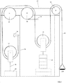
- the embodiment shown in Fig. 1 comprises a first exercise machine 10 (only part of which is shown).
- the exercise machine 10 comprises a cable 11, a first pulley 12, a second pulley 13, a third pulley 15, a fourth pulley 16 and a fifth pulley 17. These components are held in place by a frame 30, which may take any suitable form.
- the cable 11 has a distal end attached to a handle 110. In use, the user can grasp the handle 110 to perform an exercise.
- the cable 11 extends upwards from the distal end to pass over the first pulley 12, which is preferably arranged at about head height.
- the first pulley 12 is vertically orientated and is rotatable about a first axis.
- the cable 11 extends downwards from the first pulley 12, to pass under the second pulley 13, which is preferably arranged at about waist height.
- the second pulley 13 is vertically orientated, is rotatable about a second axis and can move in both directions along a first, generally vertical linear axis.
- the second pulley 13 may be arranged to move along a vertical track (not shown), for example, to allow this motion to take place.
- the cable 11 extends upwards from the second pulley 13 to pass over the third pulley 15, which is preferably arranged at a similar height to the first pulley 12.
- the third pulley 15 is vertically orientated and is rotatable about a third axis.
- the cable 11 extends away from the third pulley 15, in a generally horizontal direction that is away from the first pulley 12 and the second pulley 13, such that about a quarter of the surface of the third pulley 15 is in contact with the cable 11, to pass over the fourth pulley 16, which is preferably arranged at a similar height to the first pulley 12 and the third pulley 15.
- the fourth pulley 16 is vertically orientated and is rotatable around a fourth axis.
- the cable 11 extends downwards from the fourth pulley 16, to pass under the fifth pulley 17, which is preferably arranged at about waist height.
- the fifth pulley 17 is vertically orientated, is rotatable about a fifth axis and can move in both directions along a second linear axis. Once again, the fifth pulley 17 may slide along a vertical track during this motion.
- the cable 11 extends upwards from the fifth pulley 17, with the proximal end of the cable 11 being attached to a bolt 19.
- the bolt 19 is attached to the frame 30 of the exercise machine 10. In another embodiment of the present invention, the bolt 19 is not present and the end of the cable 11 is welded directly to the frame 30 of the exercise machine.
- the cable 11 is continuously threaded around the first pulley 12, the second pulley 13, the third pulley 15, the fourth pulley 16 and the fifth pulley 17.
- a weight stack 14 is attached to the second pulley 13 and applies an internal force, in a first (i.e. downward) direction due to gravity, to the second pulley 13.
- the weight stack 14 may be arranged to move along a vertical track (not shown), for example, to allow the weight stack to move in both directions along a first, generally vertical linear axis.
- a user force is applied by a user through the handle 110.
- a user pulls the handle 110 to lift the weight stack 14.
- the user exerts a force on the handle 110 in order to lift the weight stack 14 and in doing so, the handle 110 exerts an equal and opposite force on the user.
- the user will pull the handle 110 down to raise the weight stack 14 against gravity, and will then allow the handle 110 to rise, to lower the weight stack 14 again to complete one repetition of an exercise.
- the exercise machine 10 further includes a second cable 32, which (in this example) is entirely separate from the cable 11 discussed above.
- the second cable 32 is attached at a distal end to a winch 18 and is attached at a proximal end to the fifth pulley 17.
- the winch 18 may be operated to rotate a drum (not shown) around which the second cable 32 is wound.
- the winch 18 may therefore increase or decrease the length of the second cable 32 that extends from the winch 18.
- the winch 18 is placed generally below the fifth pulley 17.
- the fifth pulley 17 has a sprung mechanism (not shown), which biases the fifth pulley 17 upwards and provides tension in the cable between the winch 18 and the fifth pulley 17.
- the fifth pulley 17 moves in an upwards direction, away from the winch 18.
- the fifth pulley 17 moves in a downwards direction towards the winch 18.
- the third pulley 15 may comprise an entry point 29.
- the entry point 29 is indicated by a dotted line and need not be a physical feature of the embodiment.
- the fifth pulley 17 moves in the downwards direction which (in the absence of any other motion) decreases the amount of cable 11 between the entry point 29 and the handle 110.
- the fifth pulley 17 moves in the upwards direction, which increases the amount of cable 11 between the entry point 29 and the handle 110.
- the second pulley 13 may (if the handle 110 is held still) be moved along the first linear axis in both directions by changing the amount of cable between the entry point 29 and the handle 110. Assuming that the handle 110 is kept at a constant position, when the amount of cable between the entry point 29 and the handle 110 is decreased by reducing the amount of cable between the winch 18 and the fifth pulley 17, the second pulley 13 will move in the upwards direction and when the amount of cable between the entry point 29 and the handle 110 is increased by increasing the amount of cable between the winch 18 and the fifth pulley 17, the second pulley 13 will move in the downwards direction.
- the entry point is fixed with respect to the frame of the exercise machine 10, and is also preferably a point or region through which the cable 11 passes during all phases of motion of the cable 11.
- the length of cable 11 between the entry point 29 and the handle 110 is influenced by activation of the winch 18 during use of the exercise machine 10 or by the user moving the handle 110 during use of the exercise machine.
- an entry point is to be selected, it is important that a continuous length of cable extends from the entry point to the handle 110 (or, in other embodiments, to a different member with which the user interacts, such as a foot plate), and that the introduction or removal of cable at the entry point will move the weight stack 14 upwards or downwards if all other components of the exercise machine 10 are held in a stationary position.
- Fig. 1 The arrangement of components shown in Fig. 1 is schematic, and in other examples the relative positions of the components may be different. It is also envisaged that machines embodying the present invention will have further support and/or shielding components, so that the machine is sturdy and moving parts are not exposed to users any more than necessary. These further components are not shown in the figures for purposes of clarity.
- the user interacts with the handle 110 and performs a first motion when the handle 110 is moved in a first direction and a second motion when the handle 110 is moved in a second direction, which will usually be generally opposite to the first direction.
- These movements may comprise a concentric user movement and an eccentric user movement.
- a concentric user movement is a movement where the user's muscle is contracting and an eccentric user movement is a movement where the user's muscle is extending.
- the user When the user performs the first motion and moves the handle 110 through one unit of distance, the user will raise the weight by 0.5 units.
- the effective weight experienced by the user is one-half of the real weight of the weight stack 14.
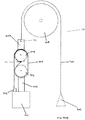
- the embodiment shown in Fig. 2 comprises a second exercise machine 20 (only part of which is shown).
- the exercise machine 20 comprises a cable 21, a first pulley 22, a second pulley 23 and a third pulley 25, again held in place by a frame 30, which may take any suitable form.
- the cable 21 has a distal end attached to a handle 210. In use, the user can grasp the handle 210 to perform an exercise.
- the cable 21 extends upwards from the distal end to pass over the first pulley 22, which is preferably arranged at about head height.
- the first pulley 22 is vertically orientated and is rotatable about a first axis.
- the cable 21 extends downwards from the first pulley 22, to pass under the second pulley 23, which is preferably arranged at about waist height.
- the second pulley 23 is vertically orientated, is rotatable about a second axis and (as before) can move in both directions along a first, generally vertical linear axis.
- the cable 21 extends upwards from the second pulley 23 to pass over the third pulley 25, which is preferably arranged at a similar height to the first pulley 22.
- the third pulley 25 is vertically orientated and is rotatable about a third axis.
- the cable 21 extends downwards from the second pulley 23, with the proximal end of the cable 11 being attached to a winch 28.
- the cable 21 is continuously threaded around the first pulley 22, the second pulley 23 and the third pulley 25.
- a weight stack 24 is attached to the second pulley 23 and applies an internal force, in a first (i.e. downward) direction due to gravity, to the moveable second pulley 23.
- the weight stack 24 may be arranged to move along a vertical track (not shown), for example, to allow the weight stack to move in both directions along a first, generally vertical linear axis.
- a user force is applied by a user through the handle 210.
- a user pulls a handle 210 to lift the weight stack 24.
- the user exerts a force on the handle 210 in order to lift the weight stack 24 and in doing so, the handle 210 exerts an equal and opposite force on the user.
- the user will pull the handle 210 down to raise the weight stack 24 against gravity, and then lower the weight stack 24 again to complete one repetition of an exercise.
- the cable enters the winch 28 may comprise an entry point. There is an initial length of cable 21 between the entry point and the handle 210.
- the second pulley 23 may (if the handle 210 is held still) be moved along the first linear axis by changing the amount of cable between the entry point and the handle 210. Assuming that the handle 210 is kept at a constant position, when the amount of cable between the entry point and the handle 210 is decreased, the second pulley 23 will move in the upwards direction and when the amount of cable between the entry point and the handle 210 is increased, the second pulley 23 will move in the downwards direction.
- a difference between the embodiment shown in Fig. 1 and the embodiment depicted in Fig. 2 is the arrangement of the winch 18, 28.
- the second cable 32 of Fig. 1 which is connected to the winch 18, is not directly connected to the handle 110.
- the arrangement of Fig. 1 is likely to provide a smoother change in effective cable length as the winch 18 is attached to a fifth pulley 17, and a lower amount of stress is put on the third pulley 15 when compared to the embodiment shown in Fig. 2 .
- the embodiment shown in Fig. 2 has two fewer pulleys and as a result is a simpler and more cost efficient arrangement.
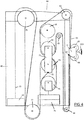
- the embodiment shown in Fig. 3 comprises a third exercise machine 40 (only part of which is shown).
- the exercise machine 40 comprises a cable 41, and first to tenth pulleys 58, 59, 42, 43, 45, 46, 47, 53, 54 55. These components are held in place by a frame 50, which may take any suitable form.
- the cable 41 has a distal end attached to a handle 410. In use, the user can grasp the handle 410 to perform an exercise.
- the cable 41 extends from the distal end to pass in-between the first and second pulleys 58, 59, which are attached to a bogey 56.
- the first and second pulleys 58, 59 are vertically orientated, with the second pulley 59 being generally directly above the first pulley 58, and are independently rotatable about respective first and second axes.
- the bogey 56 is attached to the frame 50 and may move vertically along a range of motion, preferably from a height corresponding to a user's ankles to about the user's head height and the bogey 56 may be temporarily fixed at an attachment point (or any of a series of spaced-apart attachment points) so that a user may use the handle 410 at a preferred height.
- the cable 41 extends upwards from the bogey 56, to pass over a third pulley 42, which is preferably arranged at about head height.
- the third pulley 42 is vertically orientated and is rotatable about a third axis.
- the cable 41 may have a rubber ball or a similar stop element (not shown) attached close to the distal end of the cable 41.
- the rubber ball may be located in-between the handle 410 and the bogey 56, such that if the handle 410 is removed from the distal end of the cable 41, the distal end of the cable 41 cannot pass through the first and second pulleys 58, 59.
- the cable 41 extends downwards from the third pulley 42, to pass under the fourth pulley 43, which is preferably arranged at about waist height.
- the fourth pulley 43 is vertically orientated, is rotatable about a fourth axis and can move in both directions along a first, generally vertical linear axis.
- the fourth pulley 43 may be arranged to move along a vertical track (not shown), for example, to allow this motion to take place.
- the cable 41 extends upwards from the fourth pulley 43 to pass over the fifth pulley 45, which is preferably arranged at a similar height to the third pulley 42.
- the fifth pulley 45 is vertically orientated and is rotatable around a fifth axis.
- the cable 41 extends away from the fifth pulley 45, in a generally horizontal direction that is away from the third pulley 42 and the fourth pulley 43, such that about a quarter of the surface of the fifth pulley 45 is in contact with the cable 41, to pass over the sixth pulley 46, which is preferably arranged at a similar height to the third pulley 42 and the fifth pulley 45.
- the sixth pulley 46 is vertically orientated and is rotatable around a sixth axis.
- the cable 41 extends downwards from the sixth pulley 46, to pass under the seventh pulley 47, which is preferably arranged at about waist height.
- the seventh pulley 47 is vertically orientated, is rotatable around a seventh axis and can move in both directions along a second linear axis. Once again, the seventh pulley 47 may slide along a vertical track during this motion.
- the cable 41 extends upwards from the seventh pulley 47, to pass over the eighth pulley 53, which again is preferably arranged at about waist height.
- the eighth pulley 53 is vertically orientated and is rotatable around an eighth axis.
- the cable extends downwards from the eighth pulley 53 to pass under the ninth pulley 54, which is preferably arranged at or around about foot height.
- the ninth pulley 54 is vertically orientated and is rotatable around a ninth axis.
- the cable 41 extends away from the ninth pulley 54 in a generally horizontal direction that is towards the third pulley 42 and the first pulley 58, such that about a quarter of the surface of the ninth pulley 54 is in contact with the cable 41, to pass under the tenth pulley 55, which is preferably arranged at a similar height to the ninth pulley 54.
- the tenth pulley 55 is vertically orientated and is rotatable around a tenth axis.
- the cable 41 extends upwards from the tenth pulley 55 to meet the bogey 56 at an attachment point 57; the proximal end of the cable 41 is attached to the attachment point 57.
- the attachment point 57 may not be present and the end of the cable 41 is welded directly to the bogey 56 of the exercise machine.
- the cable 41 is continuously threaded through the channel created by the first pulley 58 and the second pulley 59, and is continuously threaded around the third pulley 42, the fourth pulley 43, the fifth pulley 45, the sixth pulley 46, the seventh pulley 47, the eighth pulley 53, the ninth pulley 54 and the tenth pulley 55.
- a weight stack 44 is attached to the fourth pulley 43 and applies an internal force, in a first (i.e. downward) direction due to gravity, to the fourth pulley 43.
- the weight stack 44 may be arranged to move along a vertical track (not shown), for example, to allow the weight stack to move in both directions along a first, generally vertical linear axis.
- a user force is applied by a user through the handle 410.
- a user pulls the handle 410 to lift the weight stack 44.
- the user exerts a force on the handle 410 in order to lift the weight stack 44 and in doing so, the handle 410 exerts an equal and opposite force on the user.
- the user will pull the handle 410 away from the bogey 56 to raise the weight stack 44 against gravity, and will then move the handle 410 towards the bogey 56 to lower the weight stack 44 again to complete one repetition of an exercise.
- the exercise machine 40 further includes a second cable 52, which (in this example) is entirely separate from the cable 41 discussed above.
- the second cable 52 is attached at a distal end to a winch 48 and is attached at a proximal end to the seventh pulley 47.
- the winch 48 may be operated to rotate a drum (not shown) around which the second cable 52 is wound. The winch 48 may therefore increase or decrease the length of the second cable 52 that extends from the winch 48.
- the winch 48 is placed generally below the seventh pulley 47.
- the seventh pulley 47 has a sprung mechanism (not shown), which biases the seventh pulley 47 upwards and provides tension in the cable between the winch 48 and the seventh pulley 47.
- the seventh pulley 47 moves in an upwards direction, away from the winch 48.
- the seventh pulley 47 moves in a downwards direction towards the winch 48.
- the fifth pulley 45 may comprise an entry point. There is an initial length of cable 41 between the entry point and the handle 410. By reducing the amount of cable between the winch 48 and the seventh pulley 47, the seventh pulley 47 moves in a downwards direction which (in the absence of any other motion) decreases the amount of cable 41 between the entry point and the handle 410. By increasing the amount of cable between the winch 48 and the seventh pulley 47, the seventh pulley 47 moves in the upwards direction, which increases the amount of cable 41 between the entry point and the handle 410.
- the fourth pulley 43 may (if the handle 410 is held still) be moved along the first linear axis in both directions by changing the amount of cable between the entry point and the handle 410.
- the handle 410 Assuming that the handle 410 is kept at a constant position, when the amount of cable between the entry point and the handle 410 is decreased, the fourth pulley 43 will move in the upwards direction and when the amount of cable between the entry point and the handle 410 is increased, the fourth pulley 43 will move in a downwards direction.
- the user interacts with the handle 410 and performs a first motion when the handle 410 is moved in a first direction and a second motion when the handle 410 is moved in a second direction, which will usually be generally opposite to the first direction.
- These movements may comprise a concentric user movement and an eccentric user movement.
- a concentric user movement is a movement where the user's muscle is contracting and an eccentric user movement is where the user's muscle is extending.
- a difference between the embodiments shown in Figs. 1 and 2 and the embodiment depicted in Fig. 3 is the addition of a bogey 56.
- the bogey 56 allows a user to adjust the height of the handle 410.
- An advantage of the arrangement shown in Fig. 3 is that the user can adjust the height of the handle 410 in order to perform different exercises.
- the embodiment shown in Fig. 4 comprises a fourth exercise machine 60 (only part of which is shown).
- the exercise machine 60 comprises a first cable 61, and first to eleventh pulleys 68, 69, 62, 63, 64, 65, 66, 73, 74, 77, 78. These components are held in place by a frame 81, which may take any suitable form.
- the first cable 61 has a distal end attached to a handle 610. In use, the user can grasp the handle 610 to perform an exercise.
- the first cable 61 extends from the distal end to pass in-between the first and second pulleys 68, 69, which are attached to a bogey 70.
- the first and second pulleys 68, 69 are vertically orientated, with the second pulley 69 being generally directly above the first pulley 68, and are independently rotatable about respective first and second axes.
- the bogey 70 is attached to the frame 81 and may move vertically along a range of motion, preferably from a height corresponding to a user's ankles to about the user's head height and the bogey 70 may be temporarily fixed at an attachment point (or any of a series of spaced-apart attachment points) so that a user may use the handle 610 at a preferred height.
- the first cable 61 extends upwards from the bogey 70, to pass over a third pulley 62, which is preferably arranged at about head height.
- the third pulley 62 is vertically orientated and is rotatable about a third axis.
- the first cable 61 may have a rubber ball or a similar stop element (not shown) attached close to the distal end of the first cable 61.
- the rubber ball may be located in-between the handle 610 and the bogey 70, such that if the handle 610 is removed from the distal end of the first cable 61, the distal end of the first cable 61 cannot pass through the first and second pulleys 68, 69.
- the first cable 61 extends downwards from the third pulley 62, to pass over a fourth pulley 63, which is preferably arranged at about chest height.
- the fourth pulley 63 is vertically orientated and is rotatable about a fourth axis.
- the first cable 61 extends downwards from the fourth pulley 63, such that about a quarter of the surface of the fourth pulley 63 is in contact with the cable, to pass under the fifth pulley 64, which is preferably arranged vertically below the fourth pulley 63.
- the fifth pulley 64 is vertically orientated and is rotatable about a fifth axis and can move in both directions along a first, generally vertical linear axis.
- the first cable 61 extends upwards from the fifth pulley 64, to pass over a sixth pulley 65, which is preferably arranged in a position that is in-between the bogey 70, the fourth pulley 63 and the fifth pulley 64.
- the sixth pulley 65 is vertically orientated and is rotatable about a sixth axis.
- the first cable 61 extends downwards from the sixth pulley 65, to pass under a seventh pulley 66, which is preferably arranged at about foot height and vertically below the third pulley 62.
- the seventh pulley 66 is vertically orientated and is rotatable about a seventh axis.
- the first cable 61 extends upwards from the seventh pulley 66 to meet the bogey 70 at a first attachment point 67.
- the first attachment point 67 may not be present and the end of the first cable 61 is welded directly to the bogey 70 of the exercise machine.
- a member 71 is attached to the fifth pulley 64.
- the member 71 extends vertically downwards from the fifth pulley 64.
- the member 71 is attached to an eighth pulley 74, which is preferably arranged in the same vertical plane as the fourth 63 and fifth 64 pulleys.
- the eighth pulley 74 is vertically orientated and is rotatable about an eighth axis and can move in both directions along a first, generally vertical linear axis.
- a second attachment point 72 At the distal end of the member 71 to which the eighth pulley 74 is attached, is a second attachment point 72.
- a second cable 79 extends downwards from the second attachment point 72, to pass under a ninth pulley 73, which is preferably arranged in the same vertical plane as the fourth 63, fifth 64 and eighth 74 pulleys.
- the second attachment point 72 may not be present and the end of the second 79 cable 61 is welded directly to the bogey 70 of the exercise machine.
- the ninth pulley 73 is vertically orientated and is rotatable about a ninth axis and can move in both directions along a first, generally vertical linear axis.
- the second cable 79 extends upwards from the ninth pulley 73, passes over the eighth pulley 74 and extends downwards towards a tenth pulley 77, which is preferably arranged at about foot level.
- the tenth pulley 77 is vertically orientated and is rotatable about a tenth axis.
- the second cable 79 extends upwards from the tenth pulley 77 to pass over an eleventh pulley 78, which is preferably arranged at head height.
- the eleventh pulley 78 is vertically orientated and is rotatable about an eleventh axis.
- the cable extends in a downwards direction from the eleventh pulley 78 and is attached at a distal end to a winch 80.
- the winch 80 may be operated to rotate a drum (not shown) around which the second cable 79 is wound.
- the winch 80 is generally below the eleventh pulley 78 and at foot level.
- a weight stack 76 is attached to the ninth pulley 73 and applies an internal force, in a first (i.e. downward) direction due to gravity, to the moveable ninth pulley 73.
- the weight stack 76 may be arranged to move along a vertical track (not shown), for example, to allow the weight stack to move in both directions along a first, generally vertical linear axis.
- a user force is applied by a user through the handle 610.
- a user pulls a handle 610 to lift the weight stack 76.
- the user exerts a force on the handle 610 in order to lift the weight stack 76 and in doing so, the handle 610 exerts and equal and opposite force on the user.
- the user will pull the handle 610 away from the bogey 70 to raise the weight stack 76 against gravity, and will then move the handle 610 towards the bogey 70 to lower the weight stack 76 again to complete one repetition of an exercise.
- the sixth pulley 65 may comprise an entry point. There is an initial length of first cable 61 between the entry point and the handle 610. By moving the handle 610 away from the bogey 70, the amount of first cable 61 between the entry point and the handle 610 is increased. By moving the handle 610 towards the bogey 70, the amount of first cable 61 between the entry point and the handle 610 is decreased. By increasing the amount of cable between the entry point and the handle 610, the fifth pulley 64 moves in the upwards direction which moves the member 71 and the eighth pulley 74 in the upwards direction also. This upwards movement of the eighth pulley 74 decreases the amount of cable between the eighth pulley 74 and the second attachment point 72.
- the ninth pulley 73 may (if the winch 80 is locked) be moved along the first linear axis in both directions by changing the amount of cable between the entry point and the handle 610. Assuming that the winch 80 is locked, when the amount of first cable 61 between the entry point and the handle 610 is increased, the ninth pulley 73 will move in the upwards direction and when the amount of first cable 61 between the entry point and the handle 610 is decreased, the ninth pulley 73 will move in the downwards direction.
- the weight stack 76 will move up and down as the ninth pulley 73 moves.
- the amount of work done by the user when moving the handle 610 may be varied by adjusting how much of the second cable 79 the winch 80 pays out when the user is performing a user action.
- the user interacts with the handle 610 and performs a first motion when the handle 610 is moved in a first direction and a second motion when the handle 610 is moved in a second direction, which will usually be generally opposite to the first direction.
- These movements may comprise a concentric user movement and an eccentric user movement.
- a concentric user movement is a movement where the user's muscle is contracting and the eccentric user movement is where the user's muscle is extending.
- a difference between the embodiments shown in Figs. 1 - 3 and the embodiment shown in Fig. 4 is that there is a first cable 61 and a second cable 79, the two cable arrangements being connected by the member 71.
- An advantage of such an arrangement is that the first cable 61 is threaded through fewer pulleys than the cable 11, 21, 41 attached to the handle 110, 210, 410 of the previous embodiments. As the first cable 61 is threaded through fewer pulleys, the pulleys impart a lower resistance when compared to the number pulleys through which the cable 11, 21, 41 of the embodiments shown in Figs. 1 - 3 is threaded and hence the exercise machine 60 feels more responsive than the exercise machines 10, 20, 40 shown in Figs.
- the embodiment shown in Fig 5 comprises a fifth exercise machine 90 (only part of which is shown).
- the exercise machine 90 comprises a cable 91, and first to eighth pulleys 101, 102, 92, 93, 95, 96, 97, 98. These components are held in place by a frame 103, which may take any suitable form.
- the cable 91 has a distal end attached to a handle 910. In use, the user can grasp the handle 910 to perform an exercise.
- the cable 91 extends from the distal end to pass in between the first and second pulleys 101, 102, which are attached to a bogey 100.
- the first and second pulleys 101, 102 are vertically orientated, with the second pulley 102 being generally directly above the first pulley 101, and independently rotatable around respective first and second axes.
- the bogey 100 is attached to the frame 103 and may move vertically along a range of motion, preferably from a height corresponding to a user's ankles to about the user's head height, the bogey 100 may be temporarily fixed at an attachment point (or any other series at spaced-apart attachment points) so that a user may use the handle 910 at a preferred height.
- the cable 91 extends upwards from the bogey 100, to pass over the third pulley 92, which is preferably arranged at about head height.
- the third pulley 92 is vertically orientated and is rotatable around a third axis.
- the cable 91 may have a rubber ball or a similar stop element (not shown) attached close to the distal end of the cable 91.
- the rubber ball may be located in between the handle 910 and the bogey 100 such that if the handle 910 is removed from a distal end of the cable 91, the distal end of the cable 91 cannot pass through the first and second pulleys 101, 102.
- the cable 91 extends downwards from the third pulley 92, to pass under the fourth pulley 93, which is preferably arranged at about waist height.
- the fourth pulley 93 is vertically orientated, is rotatable about a fourth axis and can move in both directions along a first, generally vertical linear axis.
- the fourth pulley 93 may be arranged to move along a vertical track (not shown), for example, to allow this motion to take place.
- the cable 91 extends upwards from the fourth pulley 93 to pass over the fifth pulley 95, which is preferably arranged at a similar height to the third pulley 92.
- the fifth pulley 95 is vertically orientated and is rotatable around a fifth axis.
- the cable 91 extends away from the fifth pulley 95, in a generally horizontal direction that is away from the third pulley 92 and the fourth pulley 93, such that about a quarter of the surface of the fifth pulley 95 is in contact with the cable 91, to pass over the sixth pulley 96, which is preferably arranged at a similar height to the third pulley 92 and the fifth pulley 95.
- the sixth pulley 96 is vertically orientated and is rotatable around a sixth axis.
- the cable 91 extends downwards from the sixth pulley 96, to pass under the seventh pulley 97, which is preferably arranged at about foot height.
- the seventh pulley is vertically orientated and is rotatable around a seventh axis.
- the cable 91 extends away from the seventh pulley in a generally horizontal direction that is away from the seventh pulley 97 and towards the third pulley 92.
- the cable 91 passes under the eighth pulley 98 which again is preferably arranged at about foot height.
- the eighth pulley 98 is vertically orientated and is rotatable around an eighth axis.
- the cable extends upwards from the eighth pulley 98 and the proximal end is attached to a winch 99.
- the winch 99 is attached to the bogey 100.
- the cable 91 is continuously threaded through the channel created by the first pulley 101 and the second pulley 102, and is continuously threaded around the third pulley 92, the fourth pulley 93, the fifth pulley 95, the sixth pulley 96, the seventh pulley 97 and the eighth pulley 98.
- a weight stack 94 is attached to the fourth pulley 93 and applies an internal force, in a first (i.e. downward) direction due to gravity, to the fourth pulley 93.
- the weight stack 94 may be arranged to move along a vertical track (not shown), for example, to allow the weight stack to move in both directions along a first, generally vertical linear axis.
- a user force is applied by a user through the handle 910.
- a user pulls the handle 910 to lift the weight stack 94.
- a user exerts a force on the handle 910 in order to lift the weight stack 94 and in doing so, the handle 910 exerts an equal and opposite force on the user.
- the user will pull the handle 910 away from the bogey 100 to raise the weight stack 94 against gravity, and will then move the handle 910 towards the bogey 100 to lower the weight stack 94 again to complete one repetition of an exercise.
- the fifth pulley 95 may comprise an entry point. There is an initial length of cable 91 between the entry point and the handle 910. The length of the cable 91 between the entry point and the handle 910 may be changed by operation of the winch 99. By reducing the amount of cable between the winch 99 and the entry point, the amount of cable between the entry point and the handle 910 is also reduced. By increasing the amount of cable between the winch 99 and the entry point, the amount of cable between the entry point and the handle 910 is also increased.
- the fourth pulley 93 may (if the handle 910 is held still) be moved along the first linear axis in both directions by changing the length of the cable 91 between the entry point and the handle 910.
- the handle 910 is kept at a constant position
- the fourth pulley 93 will move in an upwards direction and when the length of the cable 91 between the entry point and the handle 910 is increased, the fourth pulley 93 will move in a downwards direction.
- the movement of the fourth pulley 93 will rise and lower the weight stack 94 accordingly.
- the amount of work done by the user when moving the handle 910 may be varied by adjusting the length of the cable 91 that the winch 99 pays out when the user is performing a user action.
- the user interacts with the handle 910 and performs a first motion when the handle 910 is moved in a first direction and a second motion when the handle 910 is moved in a second direction, which will usually be generally opposite to the first direction.
- These movements may comprise a concentric user movement and an eccentric user movement.
- a concentric user movement is a movement where the user's muscle is contracting and an eccentric user movement is where the user's muscle is extending.
- a difference between the embodiment shown in Fig. 3 and the embodiment depicted in Fig. 5 is the arrangement of the winch 99.
- the winch 99 is connected directly to the bogey 100.
- An advantage of attaching the winch 99 directly to the bogey 100 is that the exercise machine has two fewer pulleys and as a result is simpler and more cost efficient.
- the arrangement shown in Fig. 6 comprises a sixth exercise machine 120 (only part of which is shown).
- the exercise machine 120 comprises a first cable 121, a second cable 127, a third cable 131, first to third reels 123, 124, 125, a guide wheel 126 and first to fifth pulleys 135, 136, 122, 129, 130. These components are held in place by a frame 133, which may take any suitable form.
- the first cable 121 has a distal end attached to a handle 1010. In use, the user can grasp a handle 1010 to perform an exercise.
- the first cable 121 extends from the distal end to pass in between the first and second pulleys 135, 136, which are attached to a bogey 134.
- the first and second pulleys 135, 136 are vertically orientated, with the second pulley 136 being generally directly above the first pulley 135, and independently rotatable around respective first and second axes.
- the bogey 134 is attached to the frame 133 and may move vertically along a range of motion, preferably from a height corresponding to a user's ankles to about the user's head height and the bogey 134 may be temporarily fixed at an attachment point (or any other series of spaced-apart attachment points) so that a user may use the handle 1010 at a preferred height.
- the first cable 121 extends upwards from the bogey 134, to pass over a third pulley 122, which is preferably arranged at about head height.
- the third pulley 122 is vertically orientated and is rotatable around a third axis.
- the first cable 121 may have a rubber ball or a similar stop element (not shown) attached close to the distal end of the first cable 121.
- the rubber ball may be located in between the handle 1010 and the bogey 134, such that if the handle 1010 is removed from the distal end of the first cable 121, the distal end of the first cable 121 cannot pass through the first and second pulleys 135, 136.
- the first cable 121 extends downwards from the third pulley 122, to pass under the first reel 123, which is preferably arranged at about chest height.
- the proximal end of the first cable 121 is attached to the first reel 123, an extended length of cable is wrapped around the first reel such that multiple rotations (for example one, two, three, four or five rotations) may take place.
- the first reel 123 is vertically orientated, is rotatable around a fourth axis and is attached to a first end of a continuously variable transmission (not shown). Attached to the second end of the variable transmission, is a third reel 125.
- the third reel 125 is vertically orientated and is rotatable around the fourth axis.
- the second reel 124 is vertically orientated and is rotatable around the fourth axis.
- the second reel 124 is attached to the third reel 125 by a locking/free-wheeling mechanism (not shown).
- the second cable 127 is attached at a proximal end to the third reel 125 and is wrapped around the third reel 125 a number of times (for example one, two, three, four or five times), and extends in a generally downwards direction passing by a guide wheel 126 attached at a distal end to a weight stack 128.
- a third cable 131 is attached to the second reel 124 at a proximal end and is wrapped around the second reel 124, for example two, three, four times etc.
- the third cable 131 extends in a generally downward direction towards a fourth pulley 129.
- the fourth pulley 129 is preferably arranged at about foot height.
- the fourth pulley is vertically orientated and is rotatable around a fifth axis.
- the third cable 131 passes around the fourth pulley 129 and extends in a generally upwards direction towards a fifth pulley 130.
- the fifth pulley 130 is preferably arranged at a similar height to the third pulley 122.
- the fifth pulley 130 is vertically orientated and is rotatable around a seventh axis.
- the third cable 131 passes over a fifth pulley 130 and extends in a generally downwards direction towards a winch 132.
- the third cable 131 is attached to a proximal end to a winch 132.
- the winch 132 may be operated to rotate a drum (not shown) around which the third cable 131 is wound. The winch 132 may therefore increase or decrease the length of the third cable 131 that extends from the winch 132.
- the winch 132 is placed generally below the fifth pulley 130.
- a user force is applied by a user through the handle 1010.
- a user pulls the handle 1010 to lift the weight stack 128 and in doing so, the handle 1010 exerts an equal and opposite force on the user.
- the user will pull the handle 1010 away from the bogey 134 to raise the weight stack 128 against gravity, and will then move the handle 1010 towards the bogey 134 to lower the weight stack 128 again to complete one repetition of an exercise.
- the user interacts with the handle 1010 and performs a first motion when the handle 1010 is moved in a first direction and a second motion when the handle 910 is moved in a second direction, which will usually be generally opposite to the first direction.
- These movements may comprise a concentric user movement and an eccentric user movement.
- the locking/free-wheeling mechanism when the user performs a concentric user movement, the locking/free-wheeling mechanism is set to free-wheeling mode (either manually by the user, or through the processor detecting the movement and switching automatically to this mode).
- the concentric user movement will cause the first reel 123 to rotate in a first direction, which in Fig. 6 corresponds to a clockwise motion.
- the clockwise motion of the first reel 123 is passed through the continuously variable transmission and effects a movement in the same first direction in the third reel 125.
- the rotation of the third reel 125 will cause the weight stack 128 to rise.
- the continuously variable transmission is now set to free-wheeling mode and the locking/free-wheeling mechanism is set to locked mode. If the winch 132 is required to alter the position of the weight stack 128, the amount of third cable 131 is reduced or increased, which will cause the second reel 124 to rotate, the third reel 125 also will rotate and hence the weight stack 128 will move, without altering the length of first cable 121.
- the continuously variable transmission is set to locked mode and the locking/free-wheeling mechanism is set to free-wheeling mode and hence the weight stack 132 may be lowered.
- the fourth axis may comprise an entry point. There is an initial length of first cable 121 between the entry point and the handle 1010. By moving the handle 1010 away from the bogey 134, the amount of first cable 121 between the entry point and the handle 1010 is increased. By moving the handle 1010 towards the bogey 134, the amount of first cable 121 between the entry point and the handle 1010 is decreased. By increasing the amount of first cable 121 between the entry point and the handle 1010, the first reel 123 rotates in a first direction and hence the third reel 125 also rotates in the first direction. The rotation of the third reel 125 in the first direction decreases the amount of second cable 127 between the weight stack 128 and the third reel 125.
- the weight stack 128 may (if the winch 132 is locked) be moved along a first linear axis in both directions by changing the amount of cable between the entry point and the handle 1010. Assuming that the winch 132 is locked, when the amount of first cable 121 between the entry point and the handle 1010 is increased, the weight stack 128 will move in the upwards direction and when the amount of first cable 121 between the entry point and the handle 1010 is decreased, the weight stack 128 will move in the downwards direction.
- a difference between the embodiments shown in Figs. 1 - 5 and the arrangement depicted in Fig. 6 is the addition of first to third reels 123, 124, 125, the continuously variable transmission and the arrangement of the first to third cables 121, 127, 131.
- An advantage of such an arrangement is that the first cable 121 is threaded through fewer pulleys than the cable 11, 21, 41, 61, 91 attached to the handle 110, 210, 410, 610, 910 of the previous embodiments. As the first cable 121 is threaded through fewer pulleys, the pulleys impart a lower resistance when compared to the number pulleys through which the cable 11, 21, 41, 61, 91 of the embodiments shown in Figs.
- FIG. 1 A block diagram illustrating an exemplary embodiment of the present invention.
- FIG. 1 A block diagram illustrating an exemplary embodiment of the present invention.
- FIG. 1 A block diagram illustrating an exemplary embodiment of the present invention.
- FIG. 1 A block diagram illustrating an exemplary embodiment of the present invention.
- FIG. 1 A block diagram illustrating an exemplary embodiment of the present invention.
- FIG. 1 A block diagram illustrating an exemplary embodiment of the present invention.
- the user is likely to perform the concentric movement first, which, in the embodiments of Figs. 1 and 2 is pulling the handle 110, 210 downwards and in the embodiments of Figs. 3 - 5 , or the arrangement of fig. 6 , is moving the handle 410, 610, 910, 1010 away from the bogey 56, 70, 100, 134.
- the exercise machine 10, 20, 40, 60, 90, 120 has means for monitoring the first motion and during the first motion, the exercise machine 10, 20, 40, 60, 90, 120 applies a first mode of operation.
- the winch 18, 28, 48, 80, 99, 132 may increase the amount of cable in the system, as part of the first mode of operation. If the user moves the handle 110, 210, 410, 610, 910, 1010 through one unit of distance, the winch 18, 28, 48, 80, 99, 132 may increase the amount of cable in the system at a rate that is proportional to or commensurate with the rate at which the user moves the handle 110, 210, 410, 610, 910, 1010. In one example, the winch 18, 28, 48, 80, 99, 132 may introduce 0.5 units of cable 21, 32, 52, 79 (or in in the embodiment known from Fig. 4 , second cable 91, or in the arrangement known from Fig.
- the weight lifted by the user appears to be less than if the first mode of operation was not applied. More particularly, the effective weight experienced by the user is half of the weight that would be experienced without the operation of the winch 18, 28, 48, 80, 99, 132 (or in the arrangement known from Fig. 6 , the effective weight that the user will experience may be different, depending on the setting of the continuously variable transmission).
- the winch 18, 28, 48, 80, 99, 132 tracks the user's movement quickly and in real time, to give an effective weight that is experienced by the user that is half of the real weight, regardless of how quickly the user moves the handle 110, 210, 410, 610, 910, 1010.
- the user's movement may be monitored in any suitable way, and some examples are given below.
- a sensor may be attached to the first pulley 12, 22 (or in the case of the embodiments known from Figs. 3 , 4 , 5 , 6 , the third pulley 42, 62, 92, 122) and the sensor may be a rotational encoder.
- the sensor may detect the rate of rotation of the pulley 12, 22 (or in the case of the embodiments known from Figs.
- the pulley 12, 22 may, for example, have a marking or series of markings on it, which the sensor detects when the/each marking passes the sensor.
- the winch may take this information and apply a scaling factor in order to introduce cable into the system at a rate which is, at any moment, maintained in a pre-determined proportion to the rate at which the user is adding it to the system.
- the exercise machine 10, 20, 40, 60, 90, 120 has a distance ratio of 2 (or in the arrangement known from Fig. 6 , the ratio may be different, depending on the setting of the continuously variable transmission).
- the distance ratio is the ratio between how far the user is required to move the handle 110, 210, 410, 610, 910, 1010 to move the weight stack 14, 24, 44, 76, 94, 128 through a set unit of distance, compared to the distance through which the handle 110, 210, 410, 610, 910, 1010 must be moved to move the weight stack 14, 24, 44, 76, 94, 128 through the same set distance if the winch 18, 28, 48, 80, 99, 132 is locked and performs no activity (and in the arrangement known from Fig.
- a distance ratio of two means that the user will have to move the handle 110, 210, 410, 610, 910, 1010 through a distance that is twice the distance that the user would have to move the handle 110, 210, 410, 610, 910, 1010 if the winch 18, 28, 48, 80, 99, 132 was locked in order to move the weight stack 14, 24, 44, 76, 94, 132 through a set unit of distance.
- the exercise machine 10, 20, 40, 60, 90, 120 has means for detecting when the first motion has been completed. There are many ways to detect when the first motion has been completed and embodiments of the present invention are not limited to a specific means of detection.
- Some embodiments of the present invention may comprise a sensor for detecting distance by which the handle 110, 210, 410, 610, 910, 1010 has been moved by the user.
- the sensor may (as discussed above) be a rotational encoder and measure the rotational rate of the first pulley 12, 22 (or in the case of the embodiments known from Figs. 3 , 4 or 5 , or the arrangement of fig. 6 , the third pulley 42, 62, 92, 122) or one or more other pulleys.
- the sensor may alternatively monitor the length of cable that has passed the third pulley 15, 25 (or in the case of the embodiment known from Fig. 3 or 5 , or the arrangement of fig.
- This sensor may further comprise a memory and a processor.
- the sensor may have a value stored in the memory that represents a distance by which the handle 110, 210, 410, 610, 910, 1010 has moved for the user to have finished the first motion.
- the sensor may retrieve the value from the memory and compare the value to the sensed distance. If the sensed distance is equal to or greater than the value stored in the memory, this indicates that the user has completed the first motion. In this embodiment, no other sensing means may be required.
- inventions of the present invention may comprise a sensor for monitoring the force that the user is applying to the handle 110, 210, 410, 610, 910, 1010.
- the sensor may comprise a strain gauge attached to the second pulley 13, 23 (or in the case of the embodiments known from Figs. 3 , 5 the fourth pulley 43, 93 or in the case of the embodiment known from Fig. 4 , the eighth pulley 73, or in the case of the arrangement known from Fig. 6 , the third reel 125) (or another part of the system), such that the strain gauge monitors the force applied to the weight stack 14, 24, 44, 76, 94, 128.
- the sensor may further comprise a memory and a processor.
- the sensor may store a value in the memory, which represents the force applied to the weight stack 14, 24, 44, 76, 94, 128. Taking information from other sensors in order to calculate the distance through which the weight stack has been moved, the exercise machine 10, 20, 40, 60, 90, 120 may calculate the work done by the user during a repetition.
- the sensor may indicate that the user movement has stopped. However, this could merely indicate that the user has paused during a user motion, rather than that the user has finished a user motion.
- a number of sensors may be used in combination.
- the winch 18 is locked and does not adjust the length of cable 11 in system. If the winch is locked, once the user has completed the first motion, the user will (in the embodiment shown in figure 1 ) have lifted a weight through a distance that is half that of the increase in the distance between the handle 110 and the first pulley 12.
- a control unit detects when the user has completed the first motion. This may be detected (as described above) through a sensor attached to the first pulley 12, 22 (or in the case of the embodiments known from Figs. 3 , 4 , 5 , 6 the third pulley 42, 62, 92, 122), any other pulley, the handle 110, 210, 410, 610, 910, 1010 or any other positions where movement of the cable may be detected.
- a first sensor may monitor whether a pulley has stopped moving.
- a second sensor may monitor the amount of cable 11, 21, 41, 91 (or in the embodiment known from Fig. 4 , or from the arrangement of fig. 6 , the first cable 61, 121) that has passed over a pulley.
- the control unit may take inputs from these sensors and calculate once the user has finished the first motion.
- the user indicates that they have finished the first motion through the use of a switch on the handle 110, 210, 410, 610, 910, 1010.
- the user may use voice recognition, eye movement sensors instead of a switch, or the control unit may compare the amount of cable between the entry point and the handle 110, 210, 410, 610, 910, 1010 to a standard distance and calculate the probability that the user has finished the first motion.
- the control unit may send instructions to an indicator to display an indication to the user not to start the second motion, which may be an eccentric movement.
- the control unit may start the third mode of operation and instruct the winch 18, 28, 48, 80, 99, 132 to reduce the amount of cable 11, 21, 41, 91, (or in the embodiment known from Fig. 4 , second cable 79 or in the arrangement known from Fig. 6 , third cable 131) in the system, thereby increasing the height of the weight stack 14, 24, 44, 76, 94, 128.
- the exercise machine 10, 20, 40, 60, 90, 120 may calculate the increase in the height of the weight stack 14, 24, 44, 76, 94, 128 based on the distance ratio and instruct the winch 18, 28, 48, 80, 99, 132 to raise the weight stack 14, 24, 44, 76, 94, 128 to a height that the user would have lifted it to in the first motion if there had been no compensatory action provided by the winch 18, 28, 48, 80, 99, 132.
- the winch may raise the weight stack 14, 24, 44, 76, 94, 128 to a height that is different from the position that the user would have lifted it to in the first motion if there had been no compensatory action provided by the winch 18, 28, 48, 80, 99, 132.
- the winch 18, 28, 48, 80, 99, 132 may raise the weigh stack 14, 24, 44, 76, 94, 128, to a height that is lower or higher than the user would have lifted it to in the first motion.
- An advantage of the winch 18, 28, 48, 80, 99, 132 moving the weight stack 14, 24, 44, 76, 94, 128 is that different distance ratios for the first and second motions may be achieved, including ratios that change as the user performs a number of repetitions.
- the user may perform a set that comprises ten repetitions.
- the distance ratio may be a ratio of 2 for the first motion of the first five repetitions and the distance ratio may be a ratio of 4 for the first motion of the second five repetitions.
- an indication may be displayed to the user, indicating that the user may perform the second motion.
- the winch 18, 28, 48, 80, 99, 132 provides no compensatory motion and is simply "locked".
- the user lowers the weight through a longer distance, for each unit of distance moved by the handle 110, 210, 410, 610, 910, 1010 whilst performing the second motion than is the case whilst performing the first motion, so that the user effectively experiences a greater weight whilst performing the second motion.
- there is a distance ratio of 1 (or in the arrangement known from Fig. 6 , the user may use the continuously variable transmission to set a different distance ratio).
- the winch 18, 28, 48, 80, 99, 132 performs a compensatory motion during the second phase, or indeed a motion that increases the effective weight experienced.
- the control unit calculates once the user has finished the second motion. This may again be based on a sensor which detects once a pulley has stopped moving. In some embodiments, the control unit may receive an input from a sensor that measures how much cable has passed a pulley.
- the exercise machine 10, 20, 40, 60, 90, 120 is ready for the start of the first motion again for a new repetition.
- the control unit may start the fourth mode of operation and instruct the winch 18, 28, 48, 80, 99, 132 to increase the amount of cable 11, 21, 41, 91, (or in the embodiment known from Fig. 4 , second cable 79, or in the arrangement known from Fig. 6 , third cable 131) in the system, thereby decreasing the height of the weight stack 14, 24, 44, 76, 94, 128. It does not apply to the present example, but in some embodiments of the present invention, the user may finish the second motion and the weight stack 14, 24, 44, 76, 94, 128 may not be at the same position as when the user started the second motion.
- the exercise machine 10, 20, 40, 60, 90, 120 may calculate the amount of cable 11, 21, 41, 91 (or in the embodiment known from Fig. 4 , second cable 79 or in the arrangement known from Fig. 6 , third cable 131) that needs to be introduced into the system in order lower the weight stack 14, 24, 44, 76, 94, 128 to ground level.
- the user may perform the first motion or the second motion without the exercise machine 10, 20, 40, 60, 90, 120 making any active adjustment to the length of cable in the system.
- controls can be provided to a user to control the ratio and the workout.
- the user selects a setting that controls the amount of weight to be lifted. Alternatively, this may be permanently set, or indeed a traditional pin system may be provided to allow the user to select a number of weights in the stack to be lifted.
- the user selects whether to workout using a constant cam or an asymmetric cam (described in greater detail below) at step 302.
- the user selects the distance ratio for the concentric user movement and (separately) the eccentric user movement. In this embodiment the user selects a ratio of 2 for the concentric user movement and a ratio of 1 for the eccentric user movement.
- the exercise machine takes five inputs from a plurality of sensors (there may be more than one sensor per input) and has a separate control unit, communicatively coupled to the plurality of sensors.
- the control unit takes a number of inputs, the external force applied by the user 304, the tension at the first pulley 305, the tension at the second pulley 306, the tension at the third pulley 307, the displacement of the second pulley 308 and the displacement of the handle 309, that are communicated to the control unit and are stored in a memory of the control unit.
- the control unit retrieves from the memory a value representing how far the user will move the handle 110, 210, 410, 610, 910, 1010 and then calculates the internal force that will be applied to the user, based on the ratio selected by the user.
- the control unit may receive an input representing a unique ID associated with a user and can retrieve from a memory a value representing how far this user typically moves the handle 110, 210, 410, 610, 910, 1010.
- the control unit sends instructions to the winch 18, 28, 48, 80, 99, 132 based on these calculations.
- the control unit calculates how much cable 11, 21, 41, 91 (or in the embodiment known from Fig. 4 , second cable 79 or in the arrangement known from Fig. 6 , third cable 131) the winch 18, 28, 48, 80, 99, 132, will need to remove from the system in order for a distance ratio of 2 to be achieved as the user performs the first mode of operation.
- the amount of cable to be removed from the system is communicated to the winch 18, 28, 48, 80, 99, 132 and the winch 18, 28, 48, 80, 99, 132 removes the cable from the system as the user performs the first motion.
- the user performs the first motion and at step 313 the exercise machine 10, 20, 40, 60, 90, 120 detects once the user has finished the first motion (as discussed above).
- the exercise machine performs the third motion and instructs the winch 18, 28, 48, 80, 99, 132 to reduce the amount of cable 11, 21, 41, 91 (or in the embodiment known from Fig. 4 second cable 79 or in the arrangement known from Fig. 6 , third cable 131) in the system, based on the distance ratio, thereby increasing the height of the weight stack 14, 24, 44, 79, 91, 121.
- the control unit calculates whether to start the second mode of operation and introduce more cable 11, 21, 41, 91 (or in the embodiment known from Fig. 4 , second cable 79, or in the arrangement known from Fig. 6 , third cable 131) into the system as the user is performing the second motion. This may be based on the distance ratio indicated by the user in step 303.
- the user or a third party may indicate to the control unit that they have completed a first or second motion. This may be via a switch on any part of the exercise machine 10, 20, 40, 60, 90, 120, (particularly a switch on the handle, or a foot switch) through voice recognition or by an eye movement sensor.
- the means of indicating to the control unit that the user has completed a first or second motion may be communicatively connected to the control unit through wired or wireless means.
- an accelerometer may be attached to the handle 110, 210, 410, 610, 910, 1010 and the accelerometer may be connected to the control unit by wired or wireless means.
- the control unit may use the input from the accelerometer in order to calculate when a user has started or finished a user movement.
- a user may also perform initial first and second motions with a light weight, such as the lightest weight on the weight stack 14, 24, 44, 76, 94, 128 or, alternatively, an even lighter calibration weight, in order that the control unit can calibrate a range of motion.
- a light weight such as the lightest weight on the weight stack 14, 24, 44, 76, 94, 128 or, alternatively, an even lighter calibration weight, in order that the control unit can calibrate a range of motion.
- the control system calculates if an adjustment needs to be made to the amount of cable 11, 21, 41, 91 (or in the embodiment known from Fig. 4 , second cable 79, or in the arrangement known from Fig. 6 , third cable 131) in the system before a further first motion is started, if an adjustment to the amount of cable 11, 21, 41, 91 (or in the embodiment known from Figs. 4 , second cable 79, or in the arrangement known from Fig. 6 , third cable 131) in the system needs to be made, the control unit will instruct the winch 18, 28, 48, 80, 99, 132 to start a fourth mode of operation.
- control system provides instructions to the winch to adjust the amount of cable 11, 21, 41, 79, 91 (or in the embodiment known from Fig. 4 , the second cable 79 or in the arrangement known from Fig. 6 , the third cable 131) in the system whilst the user is performing the first motion.
- the control unit continuously monitors the performance of a user and dynamically alters the distance ratio for the first and second motions as the user is exercising.
- This ratio may be altered when the user is stationary between first and second motions or it may take place whilst the user is performing a first or a second motion.
- the distance ratio may also change as the user performs repetitions. For example, the distance ratio may require the user to work harder for the first five repetitions and may require the user to work in a relatively easy manner for the second five repetitions.
- This change in ratio may be programmable or, alternatively, the user may be able to select a change in ratio from a number of pre-set options or simply by outlining a desired ratio curve on a touch screen connected to the control unit.
- the control unit may also provide instructions to the weight stack 14, 24, 44, 76, 94, 128 or other means of providing the internal force, in order to adjust the internal force as the user is exercising. This adjustment of the internal force may take place when the user is stationary, between first and second motions or it may take place whilst the user is performing a first or a second motion.
- Embodiments of the present invention may have an asymmetric cam in place of the first pulley 12, 22 (or in the case of the embodiments known from Figs. 3 , 4 or 5 , or the arrangement of fig. 6 , the third pulley 42, 62, 92, 122) or alternatively any other pulley.
- Other embodiments may present the user with a choice of a constant cam (i.e. a regular pulley) or the asymmetric cam in place of the first pulley 12, 22 (or in the case of the embodiments known from Figs. 3 , 4 or 5 , or the arrangement of fig. 6 , the third pulley 42, 62, 92, 122) or alternatively any other pulley.
- An advantage of using an asymmetric cam as opposed to a constant cam is that the shape of the cam can be tailored to a specific workout and how a user's muscles vary in strength and hence the effective generation of an external force when moving a weight through a repetition.
- the mode of operation may change during a first or second user motion.
- the advantage of being able to change the mode of operation is that the exercise machine 10, 20, 40, 60, 90, 120 can replicate the action of an asymmetric cam.
- the resistance provided by the exercise machine to the user's motion will be relatively constant. If an asymmetric cam is used, the resistance will not be constant. For example, if the asymmetric cam has a protrusion, it may take more work to move the cable over the protrusion than it takes to move the cable over a flat part of the cam profile.
- the exercise machine can remove and introduce cable into the system as the user is performing the repetition, as described above, this will change the effective weight experienced by the user and hence aid the user movement or provide more resistance to the user movement.
- the sensors may be RFID tags or other sensing means.
- the RFID tags may comprise a sensor located adjacent to the first pulley 12, 22 (or in the case of the embodiments known from Figs. 3 , 4 or 5 , or the arrangement of fig. 6 , the third pulley 42, 62, 92, 122) and the cable 11, 21, 41, 91 (or in the embodiment known from Fig. 4 , or from the arrangement of fig. 6 the first cable 61, 121) may have markings at regular intervals along the cable.
- the sensor may monitor how quickly the markings move past the sensor and, in combination with information that describes the distance between the markings on the cable, may calculate how much cable has passed the sensor and hence how much cable is in the system and the RFID tag may communicate this to the winch 18, 28, 48, 80, 99, 132.
- a rotational encoder may be attached to the RFID tag and the sensor may directly monitor the rotation of the first pulley 12, 22 (or in the case of the embodiments known from Figs. 3 , 4 or 5 , or the arrangement of fig. 6 , the third pulley 42, 62, 92, 122) or any other pulley in the system.
- the sensor may further comprise a processor and a memory and perform calculations as to how much cable is in the system, taking either the information regarding how much cable has passed the sensor or how may rotations the first pulley 12, 22 (or in the case of the embodiments known from Figs. 3 , 4 or 5 , or the arrangement of fig. 6 , the third pulley 42, 62, 92, 122) has gone through and the sensor may perform these calculations locally.
- the sensor may simply communicate how quickly the markings pass the sensor to a remote processor and memory and the calculation may be performed remotely.
- the sensors may further comprise a strain gauge.
- the strain gauge could be located between the weight stack 14, 24, 44, 76, 94, 128 and the second pulley 13, 23 (or in the case of the embodiments known from Figs. 3 , 4 or 5 , or the arrangement of fig. 6 , the third pulley 42, 62, 92, 122).
- the strain gauge would measure the downward force exerted on the strain gauge by the weight stack 14, 24, 44, 76, 94, 128 and this information may be communicated to the control unit such that the control unit can take into account the mass of the weight stack 14, 24, 44, 76, 94, 128 that the user is lifting.
- such an arrangement may also be used to warn the user if no weights have been selected on the weight stack 14, 24, 44, 76, 94, 128 or if the pin securing the weights is missing.
- the RFID tags may have unique identification codes such that the control unit can identify which RFID it is communicating with.
- the RFID tag or any other sensor may be powered by harvesting energy from the user movements or from an external energy source.
- the sensors may be battery powered in other embodiments. In some embodiments, the sensors may be powered by mains electricity.
- the winch 18, 28, 48, 80, 99, 132 only operates when the user is stationary, in other embodiments, the operation of the winch 18, 28, 48, 80, 99, 132 may be in a step-wise manner. In other embodiments of the present invention, the winch 18, 28, 48, 80, 99, 132 operates whilst the user is performing the first or second mode of operation, and this operation may be in a continuous manner.
- the weight stack 14, 24, 44, 76, 94, 128 may, as discussed above, comprise a single mass, which cannot be changed by the user.
- the weight stack 14, 24, 44, 76, 94, 128 may comprise a number of masses, which the user can select in order to vary the internal force.
- the advantage of using the weight stack 14, 24, 44, 76, 94, 128 is that it provides an experience that a user may be familiar with, for example when compared to free weights, a standard cable machine or a standard body-part machine.
- the weight stack 14, 24, 44, 76, 94, 128 and second pulley 13, 23 or in the case of the embodiments known from Figs. 3 and 5 the fourth pulley 43, 93 or in the case of the embodiment known from Fig.
- the eighth pulley 73 may be replaced by a rotor in an electromagnetic field in some embodiments of the present invention.
- the weight stack 14, 24, 76, 94, 128 and second pulley 13, 23 (or in the case of the embodiments known from Figs. 3 , 5 the fourth pulley 43, 93 or in the case of the embodiment known from Fig. 4 , the eighth pulley 73) may be replaced by an elastic object, and the internal force is produced by deforming the elastic object.
- Other methods for producing an internal force are contemplated.
- An advantage of using a rotor in an electromagnetic field to produce the internal force is that the exercise machine may weigh less and be easier to move.
- An advantage of using an elastic object to produce the internal force is that an elastic object may be light, cheap to produce and easy to replace.
- any of the cables 11, 21, 41, 91 may be replaced by a belt in some embodiments of the present invention.
- a Kevlar reinforced cable or belt may be used.
- a belt reinforced by metal wires may be used.
- the winch 18, 28, 48, 80, 99, 132 may take the form of a motorised spool in some embodiments of the present invention.
- a linear actuator may be used.
- a linear actuator could replace the winch 18 and the cable 32 and be attached directly to the fifth pulley 17.
- a linear actuator could have a similar effect to the winch 18 it is replacing and will move the fifth pulley 17, such that the amount of cable between the third pulley 15 and the handle 110 is increased or decreased as required.
- a linear actuator could replace the winch 28 and be attached to the cable 21.
- the linear actuator will have a similar effect to the winch 28 it is replacing and will increase and decrease the amount of cable between the third pulley 25 and the handle 210.
- a linear actuator could replace the winch 48 and be attached to the cable 52 and be attached directly to the seventh pulley 47.
- a linear actuator could have a similar effect to the winch 48 it is replacing and will move the seventh pulley 47, such that the amount of cable between the fifth pulley 45 and the handle 410 is increased or decreased as required.
- a linear actuator could replace the winch 80 and be attached to the second cable 79.
- the linear actuator will have a similar effect to the winch 80 it is replacing and will increase and decrease the length of the second cable 79 between the eleventh pulley 78 and the attachment point 72.
- a linear actuator could replace the winch 99 and be attached to the cable 91.
- the linear actuator will have a similar effect to the winch 99 it is replacing and will increase and decrease the length of the cable 91 between the eighth pulley 98 and the handle 910.
- a linear actuator could replace the winch 132 and be attached to the third cable 131.
- the linear actuator will have a similar effect to the winch 132 it is replacing and will increase and decrease the length of the third cable 131 between the fifth pulley 130 and the second reel 124.
- the advantage of using a motorised spool or a linear actuator is that they are different sizes and have different power to weight ratios than the winch 18, 28, 48, 80, 99, 132. This allows the exercise machine 10, 20, 40, 60, 90, 120 to be customised for the location in which it will be operated.
- the winch 18, 28, 48, 80, 99, 132 may include the control unit.
- the control unit may be communicatively coupled with a sensor or a plurality of sensors through wired or wireless means.
- the control unit that may communicate with external devices such as such as a smart phone, table device, smart watch, smart wristband, activity tracker or other devices.
- the data received by the control unit may be from sensors on one or more of the pulleys 12, 13, 15, 16, 17, 22, 23, 25, 42, 43, 45, 46, 47, 53, 54, 55, 58, 59, 62, 63, 64, 65, 66, 68, 69, 73, 74, 77, 78, 92, 93, 95, 96, 97, 98, 101, 102, 122, 129, 130, 135, 136.
- This data may comprise information about the movement of the pulleys 12, 13, 15, 16, 17, 22, 23, 25, 42, 43, 45, 46, 47, 53, 54, 55, 58, 59, 62, 63, 64, 65, 66, 68, 69, 73, 74, 77, 78, 92, 93, 95, 96, 97, 98, 101, 102, 122, 129, 130, 135, 136.
- Other embodiments of the present invention may include a sensor on the weight stack 14, 24, 44, 76, 94, 128 and communicate to the control unit information about the internal force. Some embodiments may include sensors on the handle 110, 210, 410, 610, 910, 1010, which communicate with the control unit.
- the data collected from the handle 110, 210, 410, 610, 910, 1010 may include heart rate information.
- Other embodiments of the present information may collect information from the handle 110, 210, 410, 610, 910, 1010 that indicates a hazardous situation, for example if the user has released the handle 110, 210, 410, 610, 910, 1010 whilst performing the first or second motions.
- the control unit may comprise a microprocessor, RAM and a memory.
- the control unit may receive data from any of the sensors and store it in the memory.
- the control unit may retrieve data from the memory and perform calculations on the data.
- the output of calculations performed by the control unit may be used by the control unit to calculate whether a user is performing a first motion or a second motion.
- the control unit may calculate whether a user is performing a first motion or in the second motion.
- the control unit may be communicatively coupled to a display device.
- This display device may display may display how many repetitions a user has performed, the heart rate of a user, a user calorie count or any other information that a user may require.
- the display device may be a touchscreen device and a user may be able to input information that is used by the control unit, for example a user weight or a user age. The user might input information about the internal force such that the user does not need to directly interact with the weight stack 14, 24, 44, 76, 94, 128.
- the control unit may be communicatively coupled with an external device such as a smart phone, table device, smart watch, smart wristband, activity tracker or other device. The user may be able to input information through an external device.
- the control unit may store information that a user has input in the memory.
- the control unit may retrieve the information that a user has input from the memory and perform calculations on it.
- control unit may be able to track users through the use of a unique identification code.
- This may be a code that is input by a user through the display device or through an external device.
- the external device may automatically provide the unique identification code, for example through the MAC address of the device, by storing a code after it has been input by a user or through other paring means.
- the control unit of the present invention may be connected to a local network or a wider network such as the internet in order to upload information about users to a central server or through a distributed network.
- This information may be accessed by the user through different external devices and from a location that is different to that of the present invention.
- This information may be accessed by other exercise machines in the same location as the present invention or may be accessed by exercise machines in a different location to the present invention.
- the exercise machine 10, 20, 40, 60, 90, 120 may access such information in order to calculate the user force to impart to the user.
- a system for tracking the user's movements in real time is not required.
- the cable may be introduced between the entry point and the member at a constant rate, when the user starts the first or second motion, in order to reduce the effective weight experienced by the user.
- the cable may continue to be introduced between the entry point and the member throughout the duration of the user performing the first or the second motion.
- Such an arrangement may require a system for detecting when the user starts or finishes the first and second motions or the user may indicate that they are about to start or finish the first or second motion through the use of a switch, voice recognition or eye movement sensors.
- the arrangement may also detect that a certain amount of cable has been introduced between the entry point and the member in order to establish when the user has finished the first or the second motion.
- the cable may alternatively be introduced between the entry point and the member at, for example, a first rate and a second rate.
- the change between the first rate and the second rate may be based on an amount of cable passing the entry point or the user indicating that they wish the rate to change.
- Fig. 700 comprises an elevator mechanism 750.
- the elevator mechanism 750 comprises a weight 709, a first cable 710, a second cable 706, a first pulley 708, a second pulley 705, a third pulley 704, a first member 707, a second member 703, a winch 702 and an elevator car 701. These components are arranged in a lift shaft (not shown).
- the first cable 710 has a distal end attached to a weight 709. The first cable 710 passes upwards from the weight 709 to pass over the first pulley 708, which is preferably arranged at the top of the lift shaft.
- the first pulley 708 is vertically orientated and is rotatable about a first axis.
- a motor powers the first pulley 708.
- the first pulley 708 is grooved, such that it may grip the first cable 710 and move the first cable.
- the first cable 710 extends downwards from the first pulley 708 and the proximal end of the first cable 710 is attached to a first attachment point 711 at a distal end of the first member 707.
- the first member 707 and the second pulley 705 may comprise a first unit, so that these components are fixed to each other and the distance between them does not vary.
- the first unit is vertically orientated and can move in both directions along a first, generally vertical linear axis.
- the first unit may be arranged to move along a vertical track (not shown), for example, to allow this motion to take place.
- a third pulley 704, a second member 703 and an elevator car 701 comprise a second unit, so that these components are fixed to each other and the distance between them does not vary.
- the third pulley 704 is attached near to the distal end of the second member 703.
- the proximal end of the second member 703 is generally attached to the roof of the elevator car 701.
- the second unit is vertically orientated and can move in both directions along a second, generally vertically linear axis.
- the second unit may be arranged to move along a vertical track (not shown), for example, to allow this motion to take place.
- the second unit is generally arranged vertically below the first unit.
- a second cable 706 is attached at a distal end to the second attachment point 712.
- the second cable 706 extends downwards from the second attachment point 712 and under the third pulley 704.
- the third pulley 704 is vertically orientated and is rotatable about a third axis.
- the second cable 706 extends upwards from the third pulley 704 to pass over the second pulley 705.
- the second pulley 705 is vertically orientated and is rotatable about a second axis.
- the second cable 706 extends downwards from the second pulley 705 and is attached at a proximal end to a winch 702.
- the winch 702 is attached to the roof of the elevator car 701.
- the winch 702 may be operated to rotate a drum (not shown) around which the second cable 706 is wound.
- the winch 702 may therefore increase or decrease the length of the second cable 706 that extends from the winch 702.
- the second cable 706 is continuously threaded around the third pulley 704, over the second pulley 705 and into the winch 702.
- the first pulley 708 is a grooved drive sheave.
- the winch 702 may be either in a locked mode or in an unlocked mode.
- the winch 702 is in the locked mode, then when the motorised first pulley 708 rotates in a first rotational direction, the counterweight 709 rises and the elevator car 701 is lowered. When the motorised first pulley 708 rotates in a second, opposite rotational direction, the counterweight 709 is lowered and the elevator car 701 is raised. Each rotation of the motorised first pulley 708 raises and lowers both the elevator car 701 and the counterweight 709 by a fixed amount.
- the length of the second cable 706 between the second attachment point 712 and the winch 702 may be increased or decreased as the elevator car 701 rises and lowers due to the movement of the motorised winch 708. This will cause the elevator car 701 to move at a different rate to the counterweight 709.
- the inertia imparted to the elevator car 701 can be varied. For example, when approaching a stopping point, in order to ensure the comfort of the users, it is preferable to impart a small amount of inertia to the elevator car 701. However, in order to rapidly move the elevator car 701 up and down a lift shaft, a high amount of inertia is preferable. In order to balance these competing requirements, the winch 702 can increase or decrease the amount of second cable 706 as the elevator car 701 is moving.
- the elevator mechanism 750 may incorporate a first pulley 708 with a large inertia in order to move the elevator car 701 rapidly.
- a system with a low inertia is required.
- the winch 702 may adjust the length of the second cable 706 in-between the winch 702 and the second attachment point 712. By shortening or lengthening the length of the second cable 706, the elevator mechanism 750 can make use of a low inertia system in order to make small adjustments to the position of the elevator car 701.
- the elevator mechanism 750 In use, as the elevator mechanism 750 moves the elevator car 701 from a lower floor to a higher floor, the length of the first cable 710 between the first pulley 708 and the elevator car 701 is shortened. At the same time, as the elevator car 701 begins to move from the lower floor, the elevator mechanism 750 may lengthen the length of the second cable 706 in-between the winch 702 and the second attachment point 712 in order to reduce the acceleration experienced within the elevator car 701.
- the elevator mechanism 750 may reduce the length of the second cable 706 in-between the winch 702 and the second attachment point 712.
- the elevator mechanism 750 may lengthen the length of the second cable 706 in-between the winch 702 and the second attachment point 712 in order to reduce the deceleration experienced within the elevator car 701.
- the winch 702 may be set to a locked position by a control mechanism.
- the elevator car 701 moves at the same rate, but in the opposite direction to, the counterweight 709, both of which are dependent on the rate of rotation of the first pulley 708.
- the winch 702 may vary the length of the second cable 706 in-between the winch 702 and the second attachment point 712. In this manner, the elevator car 701 moves at a different rate to the counterweight 709 and the rate of movement of the elevator car 701 is not solely dependent on the rate of rotation of the first pulley 708.
Description
- This invention relates to a system of pulleys and weights, and in particular a system which delivers a variable amount of force to a user.
- In order to improve strength and fitness, many people lift weights. When lifting weights a user may simply perform repetitions with free weights, or a user may perform repetitions with one of a myriad of different exercise machines in order to target one or more specific muscle groups. Exercise machines have an advantage over free weights in that they allow a user to perform weight lifting in a more safe, efficient and versatile manner. Typically, exercise machines allow users to perform repetitions against a constant resistance, which may operate via a cam mechanism that is fixed at the time of manufacture and is not modifiable by the user.
- However, it recognised in the art that many users do not want to perform repetitions on exercise machines that provides a constant resistance throughout the repetition. It is advantageous for a user to be able to perform repetitions where the resistance provided by the exercise machine can vary throughout the repetition. This may be desirable, for instance, because a typical user is able to lower a much greater load than they can raise in a controlled manner.
- Exercise machines that allow a user to vary the resistance applied throughout a repetition exist in the art. However, these machines are often oversized and complicated.
-
US 5356360 discloses an exercise machine that uses a variable resistance cam to impart a variable resistance to a user performing a repetition. - Another example of an exercise machine known in the art is disclosed in
EP 2316538 . The exercise machine comprises a weight stack mounted within a moveable frame. The frame can pivot about its lower end so that its angle with respect to the vertical can be altered, such that the force imparted to a user may be varied during a repetition. -
WO94/27679 -
WO2013/009749 discloses an exercise machine for performing barbell type free weight lifting exercises which has a power cage or Smith press type frame, an elongated bar held on the frame in a substantially horizontal resting position, and an adjustable exercise mass assembly that allows a user to select an exercise weight from among a plurality of choices of different exercise weights provided by the exercise mass assembly. The exercise mass assembly is separate from the bar and any auxiliary weight plates carried on the bar. A cable and pulley system operatively connects the bar to a movable portion of the exercise mass assembly that provides the selected exercise weight. A powered actuator sets up the bar for performing a weight lifting exercise by lifting the movable portion of the exercise mass assembly up above a second portion of the exercise mass assembly that remains stationary during the particular weight lifting exercise. - It is desirable to have an exercise machine that allows a user to vary the resistance applied throughout a repetition, but is not oversized or complicated when compared to an exercise machine that provides a constant resistance.
- The present invention aims to address at least some of these problems.
- The present invention relates to a system for imparting a variable user force to a user, the system comprising: a line guide arrangement, including at least one moveable line guide which may move in both directions along a linear axis; wherein a force arrangement is arranged to apply at least one internal force to the at least one moveable line guide, wherein the at least one internal force opposes the motion of the at least one moveable line guide in a first direction along the linear axis; a member with which the user may interact so that the user force is applied to the user through the member; a line, having a distal end and a proximal end, with the distal end of the line attached to the member, the line being continuously threaded around the line guide arrangement; the system further comprising a line adjustment arrangement, wherein: the line adjustment arrangement is attached to the line, or is connected to move a component of the line guide arrangement; when the line adjustment arrangement is in a locked mode, there is a first ratio between distance moved by the member and distance moved by the force arrangement; the line adjustment arrangement is operable to remove/introduce line between an entry point and the member, or actively move the component of the line guide arrangement, to alter the ratio between distance moved by the member and distance moved by the force arrangement during movement of the member; such that the user performs a first motion when the member is moved in a first direction and performs a second motion when the member is moved in a second direction; wherein the system is configured to apply a first mode of operation during the first motion and a second mode of operation during the second motion, wherein the line adjustment arrangement changes the length of line between the entry point and the member in a different manner during the first and second modes of operation; and wherein the line adjustment arrangement is operable to apply a scaling factor to the distance moved by the member in order to remove or introduce line between the entry point and the member at a rate which is, at any moment, maintained in a pre-determined proportion to the rate at which the user moves the member.
- Preferably, the user force is proportional to the internal force and the user force may be varied by manipulating the line adjustment arrangement.
- Conveniently, the first or second mode of operation is such that the first or second motion may be performed without any active change in the length of the line between the entry point and the member being applied by the line adjustment arrangement.
- Advantageously, the system is configured to apply a third mode of operation when the member is stationary between the first and second motions, wherein the line adjustment arrangement changes the length of line between the entry point and the member.
- Preferably, the system is configured to apply a fourth mode of operation when the member is stationary between the second motion and a further first motion, wherein the line adjustment arrangement changes the length of line between the entry point and the member.
- Conveniently, the third and/or fourth modes are configured such that, following the first and the second motions, the length of line in the system is the same as before the first motion.
- Advantageously, the line adjustment arrangement is able to adjust the length of the line in the system in a continuous manner, or wherein the line adjustment arrangement is able to adjust the length of the line in the system in a step-wise manner.
- Preferably, in use, the internal force is applied by a mass within a gravitational field, or is applied by a rotor in an electromagnetic field, or is applied by the deformation of an elastic object.
- Conveniently, the line is a cable or a belt.
- Advantageously, the line adjustment arrangement comprises a motorised spool or a winch, or wherein the line adjustment arrangement comprises a linear actuator.
- Preferably, the line adjustment arrangement can be manipulated by the user, a third party, or both the user and the third party to change the length of line between the entry point and the member.
- Conveniently, the line adjustment arrangement can be manipulated through voice recognition to change the length of line between the entry point and the member or wherein the line adjustment arrangement can be manipulated with a switch to change the length of line between the entry point and the member, or wherein the line adjustment arrangement can be manipulated through eye movement recognition to change the length of line between the entry point and the member.
- Advantageously, the system further comprises a measurement arrangement to measure movement of the member.
- Preferably, the manipulation of the line adjustment arrangement is automated by a real-time system, the real-time system able to process at least the user force, the internal force and the length of line between the entry point and the member using a microprocessor, or wherein the manipulation of the line adjustment arrangement is automated by a real-time system, the real-time system able to process at least the user force, the internal force and the length line between the entry point and the member by mechanical means.
- In order that the present invention may be more readily understood, embodiments thereof will now be described, by way of example, with reference to the accompanying drawings, in which:
-
Fig. 1 is a schematic view of a system for imparting a variable user force to a user according to an embodiment of the present invention; and -
Fig. 2 is a schematic view of a system for imparting a variable user force to a user according to another embodiment of the present invention; and -
Fig. 3 is a schematic view of a system for imparting a variable user force to a user according to another embodiment of the present invention; and -
Fig. 4 is a schematic view of a system for imparting a variable user force to a user according to another embodiment of the present invention; and -
Fig. 5 is a schematic view of a system for imparting a variable user force to a user according to another embodiment of the present invention; -
Fig. 6 is a schematic view of a system for imparting a variable user force to a user; -
Fig. 7 is a flow diagram showing the steps of imparting a variable user force to a user according to another embodiment of the present invention; and - Fig. 700 is a schematic view of a system for imparting a variable user force to an object.
- The embodiment shown in
Fig. 1 comprises a first exercise machine 10 (only part of which is shown). The exercise machine 10 comprises a cable 11, a first pulley 12, a second pulley 13, a third pulley 15, a fourth pulley 16 and a fifth pulley 17. These components are held in place by aframe 30, which may take any suitable form. The cable 11 has a distal end attached to ahandle 110. In use, the user can grasp thehandle 110 to perform an exercise. The cable 11 extends upwards from the distal end to pass over the first pulley 12, which is preferably arranged at about head height. The first pulley 12 is vertically orientated and is rotatable about a first axis. The cable 11 extends downwards from the first pulley 12, to pass under the second pulley 13, which is preferably arranged at about waist height. The second pulley 13 is vertically orientated, is rotatable about a second axis and can move in both directions along a first, generally vertical linear axis. The second pulley 13 may be arranged to move along a vertical track (not shown), for example, to allow this motion to take place. - The cable 11 extends upwards from the second pulley 13 to pass over the third pulley 15, which is preferably arranged at a similar height to the first pulley 12. The third pulley 15 is vertically orientated and is rotatable about a third axis. The cable 11 extends away from the third pulley 15, in a generally horizontal direction that is away from the first pulley 12 and the second pulley 13, such that about a quarter of the surface of the third pulley 15 is in contact with the cable 11, to pass over the fourth pulley 16, which is preferably arranged at a similar height to the first pulley 12 and the third pulley 15. The fourth pulley 16 is vertically orientated and is rotatable around a fourth axis. The cable 11 extends downwards from the fourth pulley 16, to pass under the fifth pulley 17, which is preferably arranged at about waist height. The fifth pulley 17 is vertically orientated, is rotatable about a fifth axis and can move in both directions along a second linear axis. Once again, the fifth pulley 17 may slide along a vertical track during this motion.
- The cable 11 extends upwards from the fifth pulley 17, with the proximal end of the cable 11 being attached to a bolt 19. The bolt 19 is attached to the
frame 30 of the exercise machine 10. In another embodiment of the present invention, the bolt 19 is not present and the end of the cable 11 is welded directly to theframe 30 of the exercise machine. The cable 11 is continuously threaded around the first pulley 12, the second pulley 13, the third pulley 15, the fourth pulley 16 and the fifth pulley 17. Aweight stack 14 is attached to the second pulley 13 and applies an internal force, in a first (i.e. downward) direction due to gravity, to the second pulley 13. Theweight stack 14 may be arranged to move along a vertical track (not shown), for example, to allow the weight stack to move in both directions along a first, generally vertical linear axis. - A user force is applied by a user through the
handle 110. In practice, a user pulls thehandle 110 to lift theweight stack 14. The user exerts a force on thehandle 110 in order to lift theweight stack 14 and in doing so, thehandle 110 exerts an equal and opposite force on the user. In practice, the user will pull thehandle 110 down to raise theweight stack 14 against gravity, and will then allow thehandle 110 to rise, to lower theweight stack 14 again to complete one repetition of an exercise. - The exercise machine 10 further includes a second cable 32, which (in this example) is entirely separate from the cable 11 discussed above. The second cable 32 is attached at a distal end to a
winch 18 and is attached at a proximal end to the fifth pulley 17. Thewinch 18 may be operated to rotate a drum (not shown) around which the second cable 32 is wound. Thewinch 18 may therefore increase or decrease the length of the second cable 32 that extends from thewinch 18. Thewinch 18 is placed generally below the fifth pulley 17. The fifth pulley 17 has a sprung mechanism (not shown), which biases the fifth pulley 17 upwards and provides tension in the cable between thewinch 18 and the fifth pulley 17. When the amount of cable between thewinch 18 and the fifth pulley 17 is increased, the fifth pulley 17 moves in an upwards direction, away from thewinch 18. When the amount of cable between thewinch 18 and the fifth pulley 17 is decreased, the fifth pulley 17 moves in a downwards direction towards thewinch 18. - The third pulley 15 may comprise an entry point 29. The entry point 29 is indicated by a dotted line and need not be a physical feature of the embodiment. There is an initial length of cable 11 between the entry point 29 and the
handle 110. By reducing the length of cable 32 between thewinch 18 and the fifth pulley 17, the fifth pulley 17 moves in the downwards direction which (in the absence of any other motion) decreases the amount of cable 11 between the entry point 29 and thehandle 110. By increasing the amount of cable between thewinch 18 and the fifth pulley 17, the fifth pulley 17 moves in the upwards direction, which increases the amount of cable 11 between the entry point 29 and thehandle 110. The second pulley 13 may (if thehandle 110 is held still) be moved along the first linear axis in both directions by changing the amount of cable between the entry point 29 and thehandle 110. Assuming that thehandle 110 is kept at a constant position, when the amount of cable between the entry point 29 and thehandle 110 is decreased by reducing the amount of cable between thewinch 18 and the fifth pulley 17, the second pulley 13 will move in the upwards direction and when the amount of cable between the entry point 29 and thehandle 110 is increased by increasing the amount of cable between thewinch 18 and the fifth pulley 17, the second pulley 13 will move in the downwards direction. - It will be understood that a different entry point could have been chosen than the point 29 indicated on
Fig 1 . In general, it is preferred that the entry point is fixed with respect to the frame of the exercise machine 10, and is also preferably a point or region through which the cable 11 passes during all phases of motion of the cable 11. The length of cable 11 between the entry point 29 and thehandle 110 is influenced by activation of thewinch 18 during use of the exercise machine 10 or by the user moving thehandle 110 during use of the exercise machine. - If an entry point is to be selected, it is important that a continuous length of cable extends from the entry point to the handle 110 (or, in other embodiments, to a different member with which the user interacts, such as a foot plate), and that the introduction or removal of cable at the entry point will move the
weight stack 14 upwards or downwards if all other components of the exercise machine 10 are held in a stationary position. - The arrangement of components shown in
Fig. 1 is schematic, and in other examples the relative positions of the components may be different. It is also envisaged that machines embodying the present invention will have further support and/or shielding components, so that the machine is sturdy and moving parts are not exposed to users any more than necessary. These further components are not shown in the figures for purposes of clarity. - In use, the user interacts with the
handle 110 and performs a first motion when thehandle 110 is moved in a first direction and a second motion when thehandle 110 is moved in a second direction, which will usually be generally opposite to the first direction. These movements may comprise a concentric user movement and an eccentric user movement. A concentric user movement is a movement where the user's muscle is contracting and an eccentric user movement is a movement where the user's muscle is extending. - When the user performs the first motion and moves the
handle 110 through one unit of distance, the user will raise the weight by 0.5 units. The effective weight experienced by the user is one-half of the real weight of theweight stack 14. - The embodiment shown in
Fig. 2 comprises a second exercise machine 20 (only part of which is shown). Theexercise machine 20 comprises acable 21, afirst pulley 22, asecond pulley 23 and athird pulley 25, again held in place by aframe 30, which may take any suitable form. Thecable 21 has a distal end attached to ahandle 210. In use, the user can grasp thehandle 210 to perform an exercise. Thecable 21 extends upwards from the distal end to pass over thefirst pulley 22, which is preferably arranged at about head height. Thefirst pulley 22 is vertically orientated and is rotatable about a first axis. Thecable 21 extends downwards from thefirst pulley 22, to pass under thesecond pulley 23, which is preferably arranged at about waist height. Thesecond pulley 23 is vertically orientated, is rotatable about a second axis and (as before) can move in both directions along a first, generally vertical linear axis. - The
cable 21 extends upwards from thesecond pulley 23 to pass over thethird pulley 25, which is preferably arranged at a similar height to thefirst pulley 22. Thethird pulley 25 is vertically orientated and is rotatable about a third axis. Thecable 21 extends downwards from thesecond pulley 23, with the proximal end of the cable 11 being attached to awinch 28. Thecable 21 is continuously threaded around thefirst pulley 22, thesecond pulley 23 and thethird pulley 25. - A
weight stack 24 is attached to thesecond pulley 23 and applies an internal force, in a first (i.e. downward) direction due to gravity, to the moveablesecond pulley 23. Theweight stack 24 may be arranged to move along a vertical track (not shown), for example, to allow the weight stack to move in both directions along a first, generally vertical linear axis. A user force is applied by a user through thehandle 210. In practice, a user pulls ahandle 210 to lift theweight stack 24. The user exerts a force on thehandle 210 in order to lift theweight stack 24 and in doing so, thehandle 210 exerts an equal and opposite force on the user. In practice, the user will pull thehandle 210 down to raise theweight stack 24 against gravity, and then lower theweight stack 24 again to complete one repetition of an exercise. - Where the cable enters the
winch 28 may comprise an entry point. There is an initial length ofcable 21 between the entry point and thehandle 210. Thesecond pulley 23 may (if thehandle 210 is held still) be moved along the first linear axis by changing the amount of cable between the entry point and thehandle 210. Assuming that thehandle 210 is kept at a constant position, when the amount of cable between the entry point and thehandle 210 is decreased, thesecond pulley 23 will move in the upwards direction and when the amount of cable between the entry point and thehandle 210 is increased, thesecond pulley 23 will move in the downwards direction. - A difference between the embodiment shown in
Fig. 1 and the embodiment depicted inFig. 2 is the arrangement of thewinch Fig. 1 , which is connected to thewinch 18, is not directly connected to thehandle 110. The arrangement ofFig. 1 is likely to provide a smoother change in effective cable length as thewinch 18 is attached to a fifth pulley 17, and a lower amount of stress is put on the third pulley 15 when compared to the embodiment shown inFig. 2 . The embodiment shown inFig. 2 has two fewer pulleys and as a result is a simpler and more cost efficient arrangement. - The embodiment shown in
Fig. 3 comprises a third exercise machine 40 (only part of which is shown). Theexercise machine 40 comprises a cable 41, and first totenth pulleys handle 410. In use, the user can grasp thehandle 410 to perform an exercise. The cable 41 extends from the distal end to pass in-between the first and second pulleys 58, 59, which are attached to a bogey 56. The first and second pulleys 58, 59 are vertically orientated, with the second pulley 59 being generally directly above the first pulley 58, and are independently rotatable about respective first and second axes. The bogey 56 is attached to the frame 50 and may move vertically along a range of motion, preferably from a height corresponding to a user's ankles to about the user's head height and the bogey 56 may be temporarily fixed at an attachment point (or any of a series of spaced-apart attachment points) so that a user may use thehandle 410 at a preferred height. The cable 41 extends upwards from the bogey 56, to pass over a third pulley 42, which is preferably arranged at about head height. The third pulley 42 is vertically orientated and is rotatable about a third axis. - The cable 41 may have a rubber ball or a similar stop element (not shown) attached close to the distal end of the cable 41. The rubber ball may be located in-between the
handle 410 and the bogey 56, such that if thehandle 410 is removed from the distal end of the cable 41, the distal end of the cable 41 cannot pass through the first and second pulleys 58, 59. - The cable 41 extends downwards from the third pulley 42, to pass under the
fourth pulley 43, which is preferably arranged at about waist height. Thefourth pulley 43 is vertically orientated, is rotatable about a fourth axis and can move in both directions along a first, generally vertical linear axis. Thefourth pulley 43 may be arranged to move along a vertical track (not shown), for example, to allow this motion to take place. - The cable 41 extends upwards from the
fourth pulley 43 to pass over the fifth pulley 45, which is preferably arranged at a similar height to the third pulley 42. The fifth pulley 45 is vertically orientated and is rotatable around a fifth axis. The cable 41 extends away from the fifth pulley 45, in a generally horizontal direction that is away from the third pulley 42 and thefourth pulley 43, such that about a quarter of the surface of the fifth pulley 45 is in contact with the cable 41, to pass over thesixth pulley 46, which is preferably arranged at a similar height to the third pulley 42 and the fifth pulley 45. Thesixth pulley 46 is vertically orientated and is rotatable around a sixth axis. The cable 41 extends downwards from thesixth pulley 46, to pass under theseventh pulley 47, which is preferably arranged at about waist height. Theseventh pulley 47 is vertically orientated, is rotatable around a seventh axis and can move in both directions along a second linear axis. Once again, theseventh pulley 47 may slide along a vertical track during this motion. - The cable 41 extends upwards from the
seventh pulley 47, to pass over the eighth pulley 53, which again is preferably arranged at about waist height. The eighth pulley 53 is vertically orientated and is rotatable around an eighth axis. The cable extends downwards from the eighth pulley 53 to pass under the ninth pulley 54, which is preferably arranged at or around about foot height. The ninth pulley 54 is vertically orientated and is rotatable around a ninth axis. The cable 41 extends away from the ninth pulley 54 in a generally horizontal direction that is towards the third pulley 42 and the first pulley 58, such that about a quarter of the surface of the ninth pulley 54 is in contact with the cable 41, to pass under the tenth pulley 55, which is preferably arranged at a similar height to the ninth pulley 54. The tenth pulley 55 is vertically orientated and is rotatable around a tenth axis. The cable 41 extends upwards from the tenth pulley 55 to meet the bogey 56 at anattachment point 57; the proximal end of the cable 41 is attached to theattachment point 57. In another embodiment of the present invention, theattachment point 57 may not be present and the end of the cable 41 is welded directly to the bogey 56 of the exercise machine. - The cable 41 is continuously threaded through the channel created by the first pulley 58 and the second pulley 59, and is continuously threaded around the third pulley 42, the
fourth pulley 43, the fifth pulley 45, thesixth pulley 46, theseventh pulley 47, the eighth pulley 53, the ninth pulley 54 and the tenth pulley 55. Aweight stack 44 is attached to thefourth pulley 43 and applies an internal force, in a first (i.e. downward) direction due to gravity, to thefourth pulley 43. Theweight stack 44 may be arranged to move along a vertical track (not shown), for example, to allow the weight stack to move in both directions along a first, generally vertical linear axis. - A user force is applied by a user through the
handle 410. In practice, a user pulls thehandle 410 to lift theweight stack 44. The user exerts a force on thehandle 410 in order to lift theweight stack 44 and in doing so, thehandle 410 exerts an equal and opposite force on the user. In practice, the user will pull thehandle 410 away from the bogey 56 to raise theweight stack 44 against gravity, and will then move thehandle 410 towards the bogey 56 to lower theweight stack 44 again to complete one repetition of an exercise. - The
exercise machine 40 further includes a second cable 52, which (in this example) is entirely separate from the cable 41 discussed above. The second cable 52 is attached at a distal end to awinch 48 and is attached at a proximal end to theseventh pulley 47. Thewinch 48 may be operated to rotate a drum (not shown) around which the second cable 52 is wound. Thewinch 48 may therefore increase or decrease the length of the second cable 52 that extends from thewinch 48. Thewinch 48 is placed generally below theseventh pulley 47. Theseventh pulley 47 has a sprung mechanism (not shown), which biases theseventh pulley 47 upwards and provides tension in the cable between thewinch 48 and theseventh pulley 47. When the amount of cable between thewinch 48 and theseventh pulley 47 is increased, theseventh pulley 47 moves in an upwards direction, away from thewinch 48. When the amount of cable between thewinch 48 and theseventh pulley 47 is decreased, theseventh pulley 47 moves in a downwards direction towards thewinch 48. - The fifth pulley 45 may comprise an entry point. There is an initial length of cable 41 between the entry point and the
handle 410. By reducing the amount of cable between thewinch 48 and theseventh pulley 47, theseventh pulley 47 moves in a downwards direction which (in the absence of any other motion) decreases the amount of cable 41 between the entry point and thehandle 410. By increasing the amount of cable between thewinch 48 and theseventh pulley 47, theseventh pulley 47 moves in the upwards direction, which increases the amount of cable 41 between the entry point and thehandle 410. Thefourth pulley 43 may (if thehandle 410 is held still) be moved along the first linear axis in both directions by changing the amount of cable between the entry point and thehandle 410. Assuming that thehandle 410 is kept at a constant position, when the amount of cable between the entry point and thehandle 410 is decreased, thefourth pulley 43 will move in the upwards direction and when the amount of cable between the entry point and thehandle 410 is increased, thefourth pulley 43 will move in a downwards direction. - In use, the user interacts with the
handle 410 and performs a first motion when thehandle 410 is moved in a first direction and a second motion when thehandle 410 is moved in a second direction, which will usually be generally opposite to the first direction. These movements may comprise a concentric user movement and an eccentric user movement. As discussed above, a concentric user movement is a movement where the user's muscle is contracting and an eccentric user movement is where the user's muscle is extending. - A difference between the embodiments shown in
Figs. 1 and2 and the embodiment depicted inFig. 3 is the addition of a bogey 56. The bogey 56 allows a user to adjust the height of thehandle 410. An advantage of the arrangement shown inFig. 3 is that the user can adjust the height of thehandle 410 in order to perform different exercises. - The embodiment shown in
Fig. 4 comprises a fourth exercise machine 60 (only part of which is shown). Theexercise machine 60 comprises afirst cable 61, and first toeleventh pulleys frame 81, which may take any suitable form. Thefirst cable 61 has a distal end attached to ahandle 610. In use, the user can grasp thehandle 610 to perform an exercise. Thefirst cable 61 extends from the distal end to pass in-between the first andsecond pulleys bogey 70. The first andsecond pulleys second pulley 69 being generally directly above thefirst pulley 68, and are independently rotatable about respective first and second axes. Thebogey 70 is attached to theframe 81 and may move vertically along a range of motion, preferably from a height corresponding to a user's ankles to about the user's head height and thebogey 70 may be temporarily fixed at an attachment point (or any of a series of spaced-apart attachment points) so that a user may use thehandle 610 at a preferred height. Thefirst cable 61 extends upwards from thebogey 70, to pass over athird pulley 62, which is preferably arranged at about head height. Thethird pulley 62 is vertically orientated and is rotatable about a third axis. - The
first cable 61 may have a rubber ball or a similar stop element (not shown) attached close to the distal end of thefirst cable 61. The rubber ball may be located in-between thehandle 610 and thebogey 70, such that if thehandle 610 is removed from the distal end of thefirst cable 61, the distal end of thefirst cable 61 cannot pass through the first andsecond pulleys - The
first cable 61 extends downwards from thethird pulley 62, to pass over afourth pulley 63, which is preferably arranged at about chest height. Thefourth pulley 63 is vertically orientated and is rotatable about a fourth axis. - The
first cable 61 extends downwards from thefourth pulley 63, such that about a quarter of the surface of thefourth pulley 63 is in contact with the cable, to pass under thefifth pulley 64, which is preferably arranged vertically below thefourth pulley 63. Thefifth pulley 64 is vertically orientated and is rotatable about a fifth axis and can move in both directions along a first, generally vertical linear axis. - The
first cable 61 extends upwards from thefifth pulley 64, to pass over asixth pulley 65, which is preferably arranged in a position that is in-between thebogey 70, thefourth pulley 63 and thefifth pulley 64. Thesixth pulley 65 is vertically orientated and is rotatable about a sixth axis. - The
first cable 61 extends downwards from thesixth pulley 65, to pass under aseventh pulley 66, which is preferably arranged at about foot height and vertically below thethird pulley 62. Theseventh pulley 66 is vertically orientated and is rotatable about a seventh axis. Thefirst cable 61 extends upwards from theseventh pulley 66 to meet thebogey 70 at afirst attachment point 67. In another embodiment of the present invention, thefirst attachment point 67 may not be present and the end of thefirst cable 61 is welded directly to thebogey 70 of the exercise machine. - At a first end, a
member 71 is attached to thefifth pulley 64. Themember 71 extends vertically downwards from thefifth pulley 64. At a second end, themember 71 is attached to aneighth pulley 74, which is preferably arranged in the same vertical plane as the fourth 63 and fifth 64 pulleys. Theeighth pulley 74 is vertically orientated and is rotatable about an eighth axis and can move in both directions along a first, generally vertical linear axis. At the distal end of themember 71 to which theeighth pulley 74 is attached, is a second attachment point 72. - A
second cable 79 extends downwards from the second attachment point 72, to pass under aninth pulley 73, which is preferably arranged in the same vertical plane as the fourth 63, fifth 64 and eighth 74 pulleys. In another embodiment of the present invention, the second attachment point 72 may not be present and the end of the second 79cable 61 is welded directly to thebogey 70 of the exercise machine. Theninth pulley 73 is vertically orientated and is rotatable about a ninth axis and can move in both directions along a first, generally vertical linear axis. - The
second cable 79 extends upwards from theninth pulley 73, passes over theeighth pulley 74 and extends downwards towards a tenth pulley 77, which is preferably arranged at about foot level. The tenth pulley 77 is vertically orientated and is rotatable about a tenth axis. - The
second cable 79 extends upwards from the tenth pulley 77 to pass over an eleventh pulley 78, which is preferably arranged at head height. The eleventh pulley 78 is vertically orientated and is rotatable about an eleventh axis. The cable extends in a downwards direction from the eleventh pulley 78 and is attached at a distal end to awinch 80. Thewinch 80 may be operated to rotate a drum (not shown) around which thesecond cable 79 is wound. Preferably, thewinch 80 is generally below the eleventh pulley 78 and at foot level. - A weight stack 76 is attached to the
ninth pulley 73 and applies an internal force, in a first (i.e. downward) direction due to gravity, to the moveableninth pulley 73. The weight stack 76 may be arranged to move along a vertical track (not shown), for example, to allow the weight stack to move in both directions along a first, generally vertical linear axis. A user force is applied by a user through thehandle 610. A user pulls ahandle 610 to lift the weight stack 76. The user exerts a force on thehandle 610 in order to lift the weight stack 76 and in doing so, thehandle 610 exerts and equal and opposite force on the user. In practice, the user will pull thehandle 610 away from thebogey 70 to raise the weight stack 76 against gravity, and will then move thehandle 610 towards thebogey 70 to lower the weight stack 76 again to complete one repetition of an exercise. - The
sixth pulley 65 may comprise an entry point. There is an initial length offirst cable 61 between the entry point and thehandle 610. By moving thehandle 610 away from thebogey 70, the amount offirst cable 61 between the entry point and thehandle 610 is increased. By moving thehandle 610 towards thebogey 70, the amount offirst cable 61 between the entry point and thehandle 610 is decreased. By increasing the amount of cable between the entry point and thehandle 610, thefifth pulley 64 moves in the upwards direction which moves themember 71 and theeighth pulley 74 in the upwards direction also. This upwards movement of theeighth pulley 74 decreases the amount of cable between theeighth pulley 74 and the second attachment point 72. Theninth pulley 73 may (if thewinch 80 is locked) be moved along the first linear axis in both directions by changing the amount of cable between the entry point and thehandle 610. Assuming that thewinch 80 is locked, when the amount offirst cable 61 between the entry point and thehandle 610 is increased, theninth pulley 73 will move in the upwards direction and when the amount offirst cable 61 between the entry point and thehandle 610 is decreased, theninth pulley 73 will move in the downwards direction. - As the
ninth pulley 73 is attached to the weight stack 76, the weight stack 76 will move up and down as theninth pulley 73 moves. - As described below, the amount of work done by the user when moving the
handle 610 may be varied by adjusting how much of thesecond cable 79 thewinch 80 pays out when the user is performing a user action. - In use, the user interacts with the
handle 610 and performs a first motion when thehandle 610 is moved in a first direction and a second motion when thehandle 610 is moved in a second direction, which will usually be generally opposite to the first direction. These movements may comprise a concentric user movement and an eccentric user movement. A concentric user movement is a movement where the user's muscle is contracting and the eccentric user movement is where the user's muscle is extending. - A difference between the embodiments shown in
Figs. 1 - 3 and the embodiment shown inFig. 4 is that there is afirst cable 61 and asecond cable 79, the two cable arrangements being connected by themember 71. An advantage of such an arrangement is that thefirst cable 61 is threaded through fewer pulleys than thecable 11, 21, 41 attached to thehandle first cable 61 is threaded through fewer pulleys, the pulleys impart a lower resistance when compared to the number pulleys through which thecable 11, 21, 41 of the embodiments shown inFigs. 1 - 3 is threaded and hence theexercise machine 60 feels more responsive than theexercise machines Figs. 1 - 3 . Furthermore, by isolating thewinch 80 from thefirst cable 61, the user is less able to perceive the operation of thewinch 80 when compared to the embodiments of the present invention shown inFigs. 1 - 3 . If thewinch 80 of the present embodiment employs a stepper motor, the advantage of isolating the winch from the user would be more pronounced. - The embodiment shown in
Fig 5 comprises a fifth exercise machine 90 (only part of which is shown). Theexercise machine 90 comprises acable 91, and first toeighth pulleys frame 103, which may take any suitable form. Thecable 91 has a distal end attached to ahandle 910. In use, the user can grasp thehandle 910 to perform an exercise. Thecable 91 extends from the distal end to pass in between the first andsecond pulleys bogey 100. The first andsecond pulleys second pulley 102 being generally directly above thefirst pulley 101, and independently rotatable around respective first and second axes. Thebogey 100 is attached to theframe 103 and may move vertically along a range of motion, preferably from a height corresponding to a user's ankles to about the user's head height, thebogey 100 may be temporarily fixed at an attachment point (or any other series at spaced-apart attachment points) so that a user may use thehandle 910 at a preferred height. Thecable 91 extends upwards from thebogey 100, to pass over thethird pulley 92, which is preferably arranged at about head height. Thethird pulley 92 is vertically orientated and is rotatable around a third axis. - The
cable 91 may have a rubber ball or a similar stop element (not shown) attached close to the distal end of thecable 91. The rubber ball may be located in between thehandle 910 and thebogey 100 such that if thehandle 910 is removed from a distal end of thecable 91, the distal end of thecable 91 cannot pass through the first andsecond pulleys - The
cable 91 extends downwards from thethird pulley 92, to pass under thefourth pulley 93, which is preferably arranged at about waist height. Thefourth pulley 93 is vertically orientated, is rotatable about a fourth axis and can move in both directions along a first, generally vertical linear axis. Thefourth pulley 93 may be arranged to move along a vertical track (not shown), for example, to allow this motion to take place. - The
cable 91 extends upwards from thefourth pulley 93 to pass over thefifth pulley 95, which is preferably arranged at a similar height to thethird pulley 92. Thefifth pulley 95 is vertically orientated and is rotatable around a fifth axis. Thecable 91 extends away from thefifth pulley 95, in a generally horizontal direction that is away from thethird pulley 92 and thefourth pulley 93, such that about a quarter of the surface of thefifth pulley 95 is in contact with thecable 91, to pass over thesixth pulley 96, which is preferably arranged at a similar height to thethird pulley 92 and thefifth pulley 95. Thesixth pulley 96 is vertically orientated and is rotatable around a sixth axis. Thecable 91 extends downwards from thesixth pulley 96, to pass under theseventh pulley 97, which is preferably arranged at about foot height. The seventh pulley is vertically orientated and is rotatable around a seventh axis. - The
cable 91 extends away from the seventh pulley in a generally horizontal direction that is away from theseventh pulley 97 and towards thethird pulley 92. Thecable 91 passes under the eighth pulley 98 which again is preferably arranged at about foot height. The eighth pulley 98 is vertically orientated and is rotatable around an eighth axis. The cable extends upwards from the eighth pulley 98 and the proximal end is attached to awinch 99. Thewinch 99 is attached to thebogey 100. - The
cable 91 is continuously threaded through the channel created by thefirst pulley 101 and thesecond pulley 102, and is continuously threaded around thethird pulley 92, thefourth pulley 93, thefifth pulley 95, thesixth pulley 96, theseventh pulley 97 and the eighth pulley 98. A weight stack 94 is attached to thefourth pulley 93 and applies an internal force, in a first (i.e. downward) direction due to gravity, to thefourth pulley 93. The weight stack 94 may be arranged to move along a vertical track (not shown), for example, to allow the weight stack to move in both directions along a first, generally vertical linear axis. - A user force is applied by a user through the
handle 910. A user pulls thehandle 910 to lift the weight stack 94. A user exerts a force on thehandle 910 in order to lift the weight stack 94 and in doing so, thehandle 910 exerts an equal and opposite force on the user. In practice, the user will pull thehandle 910 away from thebogey 100 to raise the weight stack 94 against gravity, and will then move thehandle 910 towards thebogey 100 to lower the weight stack 94 again to complete one repetition of an exercise. - The
fifth pulley 95 may comprise an entry point. There is an initial length ofcable 91 between the entry point and thehandle 910. The length of thecable 91 between the entry point and thehandle 910 may be changed by operation of thewinch 99. By reducing the amount of cable between thewinch 99 and the entry point, the amount of cable between the entry point and thehandle 910 is also reduced. By increasing the amount of cable between thewinch 99 and the entry point, the amount of cable between the entry point and thehandle 910 is also increased. Thefourth pulley 93 may (if thehandle 910 is held still) be moved along the first linear axis in both directions by changing the length of thecable 91 between the entry point and thehandle 910. Assuming that thehandle 910 is kept at a constant position, when the length of thecable 91 between the entry point and thehandle 910 is decreased, thefourth pulley 93 will move in an upwards direction and when the length of thecable 91 between the entry point and thehandle 910 is increased, thefourth pulley 93 will move in a downwards direction. The movement of thefourth pulley 93 will rise and lower the weight stack 94 accordingly. - As described below, the amount of work done by the user when moving the
handle 910 may be varied by adjusting the length of thecable 91 that thewinch 99 pays out when the user is performing a user action. - In use, the user interacts with the
handle 910 and performs a first motion when thehandle 910 is moved in a first direction and a second motion when thehandle 910 is moved in a second direction, which will usually be generally opposite to the first direction. These movements may comprise a concentric user movement and an eccentric user movement. A concentric user movement is a movement where the user's muscle is contracting and an eccentric user movement is where the user's muscle is extending. - A difference between the embodiment shown in
Fig. 3 and the embodiment depicted inFig. 5 is the arrangement of thewinch 99. Thewinch 99 is connected directly to thebogey 100. An advantage of attaching thewinch 99 directly to thebogey 100 is that the exercise machine has two fewer pulleys and as a result is simpler and more cost efficient. - The arrangement shown in
Fig. 6 comprises a sixth exercise machine 120 (only part of which is shown). Theexercise machine 120 comprises afirst cable 121, asecond cable 127, athird cable 131, first tothird reels guide wheel 126 and first tofifth pulleys frame 133, which may take any suitable form. Thefirst cable 121 has a distal end attached to ahandle 1010. In use, the user can grasp ahandle 1010 to perform an exercise. Thefirst cable 121 extends from the distal end to pass in between the first andsecond pulleys bogey 134. The first andsecond pulleys second pulley 136 being generally directly above thefirst pulley 135, and independently rotatable around respective first and second axes. Thebogey 134 is attached to theframe 133 and may move vertically along a range of motion, preferably from a height corresponding to a user's ankles to about the user's head height and thebogey 134 may be temporarily fixed at an attachment point (or any other series of spaced-apart attachment points) so that a user may use thehandle 1010 at a preferred height. Thefirst cable 121 extends upwards from thebogey 134, to pass over athird pulley 122, which is preferably arranged at about head height. Thethird pulley 122 is vertically orientated and is rotatable around a third axis. - The
first cable 121 may have a rubber ball or a similar stop element (not shown) attached close to the distal end of thefirst cable 121. The rubber ball may be located in between thehandle 1010 and thebogey 134, such that if thehandle 1010 is removed from the distal end of thefirst cable 121, the distal end of thefirst cable 121 cannot pass through the first andsecond pulleys - The
first cable 121 extends downwards from thethird pulley 122, to pass under thefirst reel 123, which is preferably arranged at about chest height. The proximal end of thefirst cable 121 is attached to thefirst reel 123, an extended length of cable is wrapped around the first reel such that multiple rotations (for example one, two, three, four or five rotations) may take place. Thefirst reel 123 is vertically orientated, is rotatable around a fourth axis and is attached to a first end of a continuously variable transmission (not shown). Attached to the second end of the variable transmission, is athird reel 125. Thethird reel 125 is vertically orientated and is rotatable around the fourth axis. In between thefirst reel 123 and thethird reel 125 is asecond reel 124. Thesecond reel 124 is vertically orientated and is rotatable around the fourth axis. Thesecond reel 124 is attached to thethird reel 125 by a locking/free-wheeling mechanism (not shown). - The
second cable 127 is attached at a proximal end to thethird reel 125 and is wrapped around the third reel 125 a number of times (for example one, two, three, four or five times), and extends in a generally downwards direction passing by aguide wheel 126 attached at a distal end to aweight stack 128. - A
third cable 131 is attached to thesecond reel 124 at a proximal end and is wrapped around thesecond reel 124, for example two, three, four times etc. Thethird cable 131 extends in a generally downward direction towards afourth pulley 129. Thefourth pulley 129 is preferably arranged at about foot height. The fourth pulley is vertically orientated and is rotatable around a fifth axis. Thethird cable 131 passes around thefourth pulley 129 and extends in a generally upwards direction towards afifth pulley 130. Thefifth pulley 130 is preferably arranged at a similar height to thethird pulley 122. Thefifth pulley 130 is vertically orientated and is rotatable around a seventh axis. Thethird cable 131 passes over afifth pulley 130 and extends in a generally downwards direction towards awinch 132. Thethird cable 131 is attached to a proximal end to awinch 132. Thewinch 132 may be operated to rotate a drum (not shown) around which thethird cable 131 is wound. Thewinch 132 may therefore increase or decrease the length of thethird cable 131 that extends from thewinch 132. Thewinch 132 is placed generally below thefifth pulley 130. - A user force is applied by a user through the
handle 1010. A user pulls thehandle 1010 to lift theweight stack 128 and in doing so, thehandle 1010 exerts an equal and opposite force on the user. In practice, the user will pull thehandle 1010 away from thebogey 134 to raise theweight stack 128 against gravity, and will then move thehandle 1010 towards thebogey 134 to lower theweight stack 128 again to complete one repetition of an exercise. - In use, the user interacts with the
handle 1010 and performs a first motion when thehandle 1010 is moved in a first direction and a second motion when thehandle 910 is moved in a second direction, which will usually be generally opposite to the first direction. These movements may comprise a concentric user movement and an eccentric user movement. - In this arrangement, when the user performs a concentric user movement, the locking/free-wheeling mechanism is set to free-wheeling mode (either manually by the user, or through the processor detecting the movement and switching automatically to this mode). The concentric user movement will cause the
first reel 123 to rotate in a first direction, which inFig. 6 corresponds to a clockwise motion. The clockwise motion of thefirst reel 123 is passed through the continuously variable transmission and effects a movement in the same first direction in thethird reel 125. The rotation of thethird reel 125 will cause theweight stack 128 to rise. - In this arrangement, when the user has finished the concentric user movement, the continuously variable transmission is now set to free-wheeling mode and the locking/free-wheeling mechanism is set to locked mode. If the
winch 132 is required to alter the position of theweight stack 128, the amount ofthird cable 131 is reduced or increased, which will cause thesecond reel 124 to rotate, thethird reel 125 also will rotate and hence theweight stack 128 will move, without altering the length offirst cable 121. - In this arrangement, when the user performs an eccentric user movement, the continuously variable transmission is set to locked mode and the locking/free-wheeling mechanism is set to free-wheeling mode and hence the
weight stack 132 may be lowered. - The fourth axis may comprise an entry point. There is an initial length of
first cable 121 between the entry point and thehandle 1010. By moving thehandle 1010 away from thebogey 134, the amount offirst cable 121 between the entry point and thehandle 1010 is increased. By moving thehandle 1010 towards thebogey 134, the amount offirst cable 121 between the entry point and thehandle 1010 is decreased. By increasing the amount offirst cable 121 between the entry point and thehandle 1010, thefirst reel 123 rotates in a first direction and hence thethird reel 125 also rotates in the first direction. The rotation of thethird reel 125 in the first direction decreases the amount ofsecond cable 127 between theweight stack 128 and thethird reel 125. Theweight stack 128 may (if thewinch 132 is locked) be moved along a first linear axis in both directions by changing the amount of cable between the entry point and thehandle 1010. Assuming that thewinch 132 is locked, when the amount offirst cable 121 between the entry point and thehandle 1010 is increased, theweight stack 128 will move in the upwards direction and when the amount offirst cable 121 between the entry point and thehandle 1010 is decreased, theweight stack 128 will move in the downwards direction. - A difference between the embodiments shown in
Figs. 1 - 5 and the arrangement depicted inFig. 6 is the addition of first tothird reels third cables first cable 121 is threaded through fewer pulleys than thecable handle first cable 121 is threaded through fewer pulleys, the pulleys impart a lower resistance when compared to the number pulleys through which thecable Figs. 1 - 5 is threaded and hence theexercise machine 120 feels more responsive than theexercise machines Figs. 1 - 5 . Furthermore, by isolating thewinch 132 from thefirst cable 121, the user is less able to perceive the operation of thewinch 132 when compared to the embodiments of the present invention shown inFigs. 1 - 5 . If thewinch 132 of the present embodiment employs a stepper motor, the advantage of isolating thewinch 132 from the user would be more pronounced. - Other embodiments of the present invention may replace the
handle bogey - An example of use of the
exercise machines - The user is likely to perform the concentric movement first, which, in the embodiments of
Figs. 1 and2 is pulling thehandle Figs. 3 - 5 , or the arrangement offig. 6 , is moving thehandle bogey exercise machine exercise machine - As the user performs the first motion, the
winch handle winch handle winch cable 21, 32, 52, 79 (or in in the embodiment known fromFig. 4 ,second cable 91, or in the arrangement known fromFig. 6 , third cable, 131) into the system. This means that for every unit of increase in distance between thehandle first pulley Fig. 6 , the distance that the user will raise the weight may be different, depending on the setting of the continuously variable transm ission). - In this example, as the user performs the first motion, the weight lifted by the user appears to be less than if the first mode of operation was not applied. More particularly, the effective weight experienced by the user is half of the weight that would be experienced without the operation of the
winch Fig. 6 , the effective weight that the user will experience may be different, depending on the setting of the continuously variable transmission). - Ideally, the
winch handle Figs. 3 ,4 ,5 ,6 , thethird pulley Figs. 3 ,4 or5 , or the arrangement offig. 6 , thethird pulley Figs. 3 ,4 or5 , or the arrangement offig. 6 , thethird pulley - In this embodiment of the present invention, the
exercise machine Fig. 6 , the ratio may be different, depending on the setting of the continuously variable transmission). The distance ratio is the ratio between how far the user is required to move thehandle weight stack handle weight stack winch Fig. 6 , the setting of the continuously variable transmission is locked). A distance ratio of two means that the user will have to move thehandle handle winch weight stack - The
exercise machine - Some embodiments of the present invention may comprise a sensor for detecting distance by which the
handle Figs. 3 ,4 or5 , or the arrangement offig. 6 , thethird pulley Fig. 3 or5 , or the arrangement offig. 6 , thefifth pulley Fig. 4 the seventh pulley 78). This sensor may further comprise a memory and a processor. The sensor may have a value stored in the memory that represents a distance by which thehandle - Other embodiments of the present invention may comprise a sensor for monitoring the force that the user is applying to the
handle Figs. 3 ,5 thefourth pulley Fig. 4 , theeighth pulley 73, or in the case of the arrangement known fromFig. 6 , the third reel 125) (or another part of the system), such that the strain gauge monitors the force applied to theweight stack weight stack exercise machine - When the rate of change of force with respect to time is equal to zero (or is below a threshold value), the sensor may indicate that the user movement has stopped. However, this could merely indicate that the user has paused during a user motion, rather than that the user has finished a user motion.
- In other embodiments of the present invention, in order to determine whether the user has completed the first motion, a number of sensors may be used in combination.
- Taking the embodiment known from
Fig. 1 as an example, as the user performs the first motion, thewinch 18 is locked and does not adjust the length of cable 11 in system. If the winch is locked, once the user has completed the first motion, the user will (in the embodiment shown infigure 1 ) have lifted a weight through a distance that is half that of the increase in the distance between thehandle 110 and the first pulley 12. - A control unit detects when the user has completed the first motion. This may be detected (as described above) through a sensor attached to the first pulley 12, 22 (or in the case of the embodiments known from
Figs. 3 ,4 ,5 ,6 thethird pulley handle cable 11, 21, 41, 91 (or in the embodiment known fromFig. 4 , or from the arrangement offig. 6 , thefirst cable 61, 121) that has passed over a pulley. The control unit may take inputs from these sensors and calculate once the user has finished the first motion. - In some embodiments, once the user has stopped moving, the user indicates that they have finished the first motion through the use of a switch on the
handle handle - In this embodiment, there is a third mode of operation after the first. Once the user has performed the first motion, the control unit may send instructions to an indicator to display an indication to the user not to start the second motion, which may be an eccentric movement. Once the user has completed the first motion, the control unit may start the third mode of operation and instruct the
winch cable Fig. 4 ,second cable 79 or in the arrangement known fromFig. 6 , third cable 131) in the system, thereby increasing the height of theweight stack exercise machine weight stack winch weight stack winch - In other embodiments of the present invention, the winch may raise the
weight stack winch winch weigh stack winch weight stack - Once the
winch weight stack winch handle Fig. 6 , the user may use the continuously variable transmission to set a different distance ratio). - In other examples the
winch - The control unit calculates once the user has finished the second motion. This may again be based on a sensor which detects once a pulley has stopped moving. In some embodiments, the control unit may receive an input from a sensor that measures how much cable has passed a pulley.
- Once the second motion has finished, the
exercise machine - After the second motion and before a further first motion, there may be a fourth mode of operation. Once the user has completed the second motion, the control unit may start the fourth mode of operation and instruct the
winch cable Fig. 4 ,second cable 79, or in the arrangement known fromFig. 6 , third cable 131) in the system, thereby decreasing the height of theweight stack weight stack exercise machine cable 11, 21, 41, 91 (or in the embodiment known fromFig. 4 ,second cable 79 or in the arrangement known fromFig. 6 , third cable 131) that needs to be introduced into the system in order lower theweight stack - In some embodiments of the present invention, the user may perform the first motion or the second motion without the
exercise machine - With reference to
Fig. 7 , controls can be provided to a user to control the ratio and the workout. - At
step 301, the user selects a setting that controls the amount of weight to be lifted. Alternatively, this may be permanently set, or indeed a traditional pin system may be provided to allow the user to select a number of weights in the stack to be lifted. Optionally, the user then selects whether to workout using a constant cam or an asymmetric cam (described in greater detail below) atstep 302. Atstep 303, the user selects the distance ratio for the concentric user movement and (separately) the eccentric user movement. In this embodiment the user selects a ratio of 2 for the concentric user movement and a ratio of 1 for the eccentric user movement. - In this example, in order to provide a good level of monitoring and to increase the accuracy of the monitoring, the exercise machine takes five inputs from a plurality of sensors (there may be more than one sensor per input) and has a separate control unit, communicatively coupled to the plurality of sensors. The control unit takes a number of inputs, the external force applied by the
user 304, the tension at thefirst pulley 305, the tension at thesecond pulley 306, the tension at thethird pulley 307, the displacement of thesecond pulley 308 and the displacement of thehandle 309, that are communicated to the control unit and are stored in a memory of the control unit. The control unit retrieves from the memory a value representing how far the user will move thehandle handle winch - At
step 310, the control unit calculates howmuch cable 11, 21, 41, 91 (or in the embodiment known fromFig. 4 ,second cable 79 or in the arrangement known fromFig. 6 , third cable 131) thewinch winch winch - The user performs the first motion and at
step 313 theexercise machine step 314, the exercise machine performs the third motion and instructs thewinch cable 11, 21, 41, 91 (or in the embodiment known fromFig. 4 second cable 79 or in the arrangement known fromFig. 6 , third cable 131) in the system, based on the distance ratio, thereby increasing the height of theweight stack - At step 315, the control unit calculates whether to start the second mode of operation and introduce
more cable 11, 21, 41, 91 (or in the embodiment known fromFig. 4 ,second cable 79, or in the arrangement known fromFig. 6 , third cable 131) into the system as the user is performing the second motion. This may be based on the distance ratio indicated by the user instep 303. - In other embodiments of the present invention, the user or a third party may indicate to the control unit that they have completed a first or second motion. This may be via a switch on any part of the
exercise machine handle - A user may also perform initial first and second motions with a light weight, such as the lightest weight on the
weight stack - Once the user has finished the second motion, the control system then calculates if an adjustment needs to be made to the amount of
cable 11, 21, 41, 91 (or in the embodiment known fromFig. 4 ,second cable 79, or in the arrangement known fromFig. 6 , third cable 131) in the system before a further first motion is started, if an adjustment to the amount ofcable 11, 21, 41, 91 (or in the embodiment known fromFigs. 4 ,second cable 79, or in the arrangement known fromFig. 6 , third cable 131) in the system needs to be made, the control unit will instruct thewinch cable Fig. 4 , thesecond cable 79 or in the arrangement known fromFig. 6 , the third cable 131) in the system whilst the user is performing the first motion. - In some embodiments, the control unit continuously monitors the performance of a user and dynamically alters the distance ratio for the first and second motions as the user is exercising. This ratio may be altered when the user is stationary between first and second motions or it may take place whilst the user is performing a first or a second motion. The distance ratio may also change as the user performs repetitions. For example, the distance ratio may require the user to work harder for the first five repetitions and may require the user to work in a relatively easy manner for the second five repetitions. This change in ratio may be programmable or, alternatively, the user may be able to select a change in ratio from a number of pre-set options or simply by outlining a desired ratio curve on a touch screen connected to the control unit. The control unit may also provide instructions to the
weight stack - Embodiments of the present invention may have an asymmetric cam in place of the first pulley 12, 22 (or in the case of the embodiments known from
Figs. 3 ,4 or5 , or the arrangement offig. 6 , thethird pulley Figs. 3 ,4 or5 , or the arrangement offig. 6 , thethird pulley - In some embodiments, the mode of operation may change during a first or second user motion. The advantage of being able to change the mode of operation is that the
exercise machine - In embodiments of the present invention that use sensors to monitor the movement of the pulleys or the amount of cable in the system, the sensors may be RFID tags or other sensing means. In some embodiments, the RFID tags may comprise a sensor located adjacent to the first pulley 12, 22 (or in the case of the embodiments known from
Figs. 3 ,4 or5 , or the arrangement offig. 6 , thethird pulley cable 11, 21, 41, 91 (or in the embodiment known fromFig. 4 , or from the arrangement offig. 6 thefirst cable 61, 121) may have markings at regular intervals along the cable. The sensor may monitor how quickly the markings move past the sensor and, in combination with information that describes the distance between the markings on the cable, may calculate how much cable has passed the sensor and hence how much cable is in the system and the RFID tag may communicate this to thewinch Figs. 3 ,4 or5 , or the arrangement offig. 6 , thethird pulley Figs. 3 ,4 or5 , or the arrangement offig. 6 , thethird pulley - The sensors may further comprise a strain gauge. In the embodiment shown in
Fig. 1 , the strain gauge could be located between theweight stack Figs. 3 ,4 or5 , or the arrangement offig. 6 , thethird pulley weight stack weight stack weight stack - The RFID tags may have unique identification codes such that the control unit can identify which RFID it is communicating with. The RFID tag or any other sensor may be powered by harvesting energy from the user movements or from an external energy source. The sensors may be battery powered in other embodiments. In some embodiments, the sensors may be powered by mains electricity.
- In some embodiments of the present invention, the
winch winch winch - The
weight stack weight stack weight stack weight stack Figs. 3 and5 thefourth pulley Fig. 4 , the eighth pulley 73) may be replaced by a rotor in an electromagnetic field in some embodiments of the present invention. In other embodiments of the present invention, theweight stack Figs. 3 ,5 thefourth pulley Fig. 4 , the eighth pulley 73) may be replaced by an elastic object, and the internal force is produced by deforming the elastic object. Other methods for producing an internal force are contemplated. An advantage of using a rotor in an electromagnetic field to produce the internal force, is that the exercise machine may weigh less and be easier to move. An advantage of using an elastic object to produce the internal force is that an elastic object may be light, cheap to produce and easy to replace. - Any of the
cables 11, 21, 41, 91 (or in the embodiment known fromFig 4 , the first andsecond cables Fig. 6 the first, second andthird cables - The
winch Fig. 1 , a linear actuator could replace thewinch 18 and the cable 32 and be attached directly to the fifth pulley 17. In the embodiment known fromFig. 1 , a linear actuator could have a similar effect to thewinch 18 it is replacing and will move the fifth pulley 17, such that the amount of cable between the third pulley 15 and thehandle 110 is increased or decreased as required. - In the
exercise machine 20 shown inFig. 2 , a linear actuator could replace thewinch 28 and be attached to thecable 21. In the embodiment known fromFig 2 , the linear actuator will have a similar effect to thewinch 28 it is replacing and will increase and decrease the amount of cable between thethird pulley 25 and thehandle 210. - In the
exercise machine 40 shown inFig. 3 , a linear actuator could replace thewinch 48 and be attached to the cable 52 and be attached directly to theseventh pulley 47. In the embodiment known fromFig. 3 , a linear actuator could have a similar effect to thewinch 48 it is replacing and will move theseventh pulley 47, such that the amount of cable between the fifth pulley 45 and thehandle 410 is increased or decreased as required. - In the
exercise machine 60 shown inFig. 4 , a linear actuator could replace thewinch 80 and be attached to thesecond cable 79. In the embodiment known fromFig. 4 , the linear actuator will have a similar effect to thewinch 80 it is replacing and will increase and decrease the length of thesecond cable 79 between the eleventh pulley 78 and the attachment point 72. - In the
exercise machine 90 shown inFig. 5 , a linear actuator could replace thewinch 99 and be attached to thecable 91. In the embodiment known fromFig. 5 , the linear actuator will have a similar effect to thewinch 99 it is replacing and will increase and decrease the length of thecable 91 between the eighth pulley 98 and thehandle 910. - In the
exercise machine 120 shown inFig. 6 , a linear actuator could replace thewinch 132 and be attached to thethird cable 131. In the arrangement known fromFig. 6 , the linear actuator will have a similar effect to thewinch 132 it is replacing and will increase and decrease the length of thethird cable 131 between thefifth pulley 130 and thesecond reel 124. - The advantage of using a motorised spool or a linear actuator is that they are different sizes and have different power to weight ratios than the
winch exercise machine - In some embodiments, the
winch pulleys pulleys weight stack handle handle handle handle - The control unit may comprise a microprocessor, RAM and a memory. The control unit may receive data from any of the sensors and store it in the memory. The control unit may retrieve data from the memory and perform calculations on the data. The output of calculations performed by the control unit may be used by the control unit to calculate whether a user is performing a first motion or a second motion. The control unit may calculate whether a user is performing a first motion or in the second motion.
- The control unit may be communicatively coupled to a display device. This display device may display may display how many repetitions a user has performed, the heart rate of a user, a user calorie count or any other information that a user may require. The display device may be a touchscreen device and a user may be able to input information that is used by the control unit, for example a user weight or a user age. The user might input information about the internal force such that the user does not need to directly interact with the
weight stack - In some embodiments, the control unit may be able to track users through the use of a unique identification code. This may be a code that is input by a user through the display device or through an external device. Alternatively the external device may automatically provide the unique identification code, for example through the MAC address of the device, by storing a code after it has been input by a user or through other paring means.
- The control unit of the present invention may be connected to a local network or a wider network such as the internet in order to upload information about users to a central server or through a distributed network. This information may be accessed by the user through different external devices and from a location that is different to that of the present invention. This information may be accessed by other exercise machines in the same location as the present invention or may be accessed by exercise machines in a different location to the present invention. The
exercise machine - In other arrangements not embodying of the present invention, a system for tracking the user's movements in real time is not required. The cable may be introduced between the entry point and the member at a constant rate, when the user starts the first or second motion, in order to reduce the effective weight experienced by the user. The cable may continue to be introduced between the entry point and the member throughout the duration of the user performing the first or the second motion. Such an arrangement may require a system for detecting when the user starts or finishes the first and second motions or the user may indicate that they are about to start or finish the first or second motion through the use of a switch, voice recognition or eye movement sensors. The arrangement may also detect that a certain amount of cable has been introduced between the entry point and the member in order to establish when the user has finished the first or the second motion. The cable may alternatively be introduced between the entry point and the member at, for example, a first rate and a second rate. The change between the first rate and the second rate may be based on an amount of cable passing the entry point or the user indicating that they wish the rate to change.
- Another arrangement not embodying the present invention may be applied to an elevator/lift mechanism, as shown in Fig. 700. Fig. 700 comprises an
elevator mechanism 750. Theelevator mechanism 750 comprises aweight 709, afirst cable 710, asecond cable 706, afirst pulley 708, asecond pulley 705, athird pulley 704, afirst member 707, asecond member 703, awinch 702 and anelevator car 701. These components are arranged in a lift shaft (not shown). Thefirst cable 710 has a distal end attached to aweight 709. Thefirst cable 710 passes upwards from theweight 709 to pass over thefirst pulley 708, which is preferably arranged at the top of the lift shaft. Thefirst pulley 708 is vertically orientated and is rotatable about a first axis. A motor (not shown) powers thefirst pulley 708. Thefirst pulley 708 is grooved, such that it may grip thefirst cable 710 and move the first cable. Thefirst cable 710 extends downwards from thefirst pulley 708 and the proximal end of thefirst cable 710 is attached to afirst attachment point 711 at a distal end of thefirst member 707. - Attached towards the proximal end of the
first member 707 is asecond pulley 705. At the proximal end of thefirst member 707 is asecond attachment point 712. Thefirst member 707 and thesecond pulley 705 may comprise a first unit, so that these components are fixed to each other and the distance between them does not vary. The first unit is vertically orientated and can move in both directions along a first, generally vertical linear axis. The first unit may be arranged to move along a vertical track (not shown), for example, to allow this motion to take place. - A
third pulley 704, asecond member 703 and anelevator car 701 comprise a second unit, so that these components are fixed to each other and the distance between them does not vary. Thethird pulley 704 is attached near to the distal end of thesecond member 703. The proximal end of thesecond member 703 is generally attached to the roof of theelevator car 701. The second unit is vertically orientated and can move in both directions along a second, generally vertically linear axis. The second unit may be arranged to move along a vertical track (not shown), for example, to allow this motion to take place. The second unit is generally arranged vertically below the first unit. - A
second cable 706 is attached at a distal end to thesecond attachment point 712. Thesecond cable 706 extends downwards from thesecond attachment point 712 and under thethird pulley 704. Thethird pulley 704 is vertically orientated and is rotatable about a third axis. Thesecond cable 706 extends upwards from thethird pulley 704 to pass over thesecond pulley 705. Thesecond pulley 705 is vertically orientated and is rotatable about a second axis. Thesecond cable 706 extends downwards from thesecond pulley 705 and is attached at a proximal end to awinch 702. Thewinch 702 is attached to the roof of theelevator car 701. Thewinch 702 may be operated to rotate a drum (not shown) around which thesecond cable 706 is wound. Thewinch 702 may therefore increase or decrease the length of thesecond cable 706 that extends from thewinch 702. - The
second cable 706 is continuously threaded around thethird pulley 704, over thesecond pulley 705 and into thewinch 702. - In some examples, the
first pulley 708 is a grooved drive sheave. - In use, the
winch 702 may be either in a locked mode or in an unlocked mode. - If the
winch 702 is in the locked mode, then when the motorisedfirst pulley 708 rotates in a first rotational direction, thecounterweight 709 rises and theelevator car 701 is lowered. When the motorisedfirst pulley 708 rotates in a second, opposite rotational direction, thecounterweight 709 is lowered and theelevator car 701 is raised. Each rotation of the motorisedfirst pulley 708 raises and lowers both theelevator car 701 and thecounterweight 709 by a fixed amount. - If the
winch 702 is in the unlocked mode, the length of thesecond cable 706 between thesecond attachment point 712 and thewinch 702 may be increased or decreased as theelevator car 701 rises and lowers due to the movement of themotorised winch 708. This will cause theelevator car 701 to move at a different rate to thecounterweight 709. - The advantage of such an arrangement is that the inertia imparted to the
elevator car 701 can be varied. For example, when approaching a stopping point, in order to ensure the comfort of the users, it is preferable to impart a small amount of inertia to theelevator car 701. However, in order to rapidly move theelevator car 701 up and down a lift shaft, a high amount of inertia is preferable. In order to balance these competing requirements, thewinch 702 can increase or decrease the amount ofsecond cable 706 as theelevator car 701 is moving. - In use, the
elevator mechanism 750 may incorporate afirst pulley 708 with a large inertia in order to move theelevator car 701 rapidly. However, when theelevator car 701 is approaching a stopping point, for example at a requested floor, a system with a low inertia is required. When the car is approaching a stopping point, thewinch 702 may adjust the length of thesecond cable 706 in-between thewinch 702 and thesecond attachment point 712. By shortening or lengthening the length of thesecond cable 706, theelevator mechanism 750 can make use of a low inertia system in order to make small adjustments to the position of theelevator car 701. - In use, as the
elevator mechanism 750 moves theelevator car 701 from a lower floor to a higher floor, the length of thefirst cable 710 between thefirst pulley 708 and theelevator car 701 is shortened. At the same time, as theelevator car 701 begins to move from the lower floor, theelevator mechanism 750 may lengthen the length of thesecond cable 706 in-between thewinch 702 and thesecond attachment point 712 in order to reduce the acceleration experienced within theelevator car 701. - As the
elevator car 701 moves up the lift shaft, theelevator mechanism 750 may reduce the length of thesecond cable 706 in-between thewinch 702 and thesecond attachment point 712. - As the
elevator car 701 approaches the higher floor, theelevator mechanism 750 may lengthen the length of thesecond cable 706 in-between thewinch 702 and thesecond attachment point 712 in order to reduce the deceleration experienced within theelevator car 701. - In a first mode of operation, the
winch 702 may be set to a locked position by a control mechanism. In this mode of operation, theelevator car 701 moves at the same rate, but in the opposite direction to, thecounterweight 709, both of which are dependent on the rate of rotation of thefirst pulley 708. - In a second mode of operation, the
winch 702 may vary the length of thesecond cable 706 in-between thewinch 702 and thesecond attachment point 712. In this manner, theelevator car 701 moves at a different rate to thecounterweight 709 and the rate of movement of theelevator car 701 is not solely dependent on the rate of rotation of thefirst pulley 708. - When used in this specification and claims, the terms "comprises" and "comprising" and variations thereof mean that the specified features, steps or integers are included. The terms are not to be interpreted to exclude the presence of other features, steps or components.
- The features disclosed in the foregoing description, or the following claims, or the accompanying drawings, expressed in their specific forms or in terms of a means for performing the disclosed function, or a method or process for attaining the disclosed result, as appropriate, may, separately, or in any combination of such features, be utilised for realising the invention in diverse forms thereof. However, the scope of protection of the invention is defined by the appended claims.
Claims (14)
- A system for imparting a variable user force to a user, the system comprising:a line guide arrangement, including at least one moveable line guide (13, 23, 43, 73, 93) which may move in both directions along a linear axis;wherein a force arrangement (14, 24, 44, 76, 94) is arranged to apply at least one internal force to the at least one moveable line guide (13, 23, 43, 73, 93), wherein the at least one internal force opposes the motion of the at least one moveable line guide (13, 23, 43, 73, 93) in a first direction along the linear axis;a member (110, 210, 410, 610, 910) with which the user may interact so that the user force is applied to the user through the member (110, 210, 410, 610, 910);a line (11, 21, 41, 61, 91), having a distal end and a proximal end, with the distal end of the line (11, 21, 41, 61, 91) attached to the member (110, 210, 410, 610, 910), the line (11, 21, 41, 61, 91) being continuously threaded around the line guide arrangement;the system further comprising a line adjustment arrangement (18, 28, 48, 80, 99), wherein:the line adjustment arrangement (18, 28, 48, 80, 99) is attached to the line (11, 21, 41, 61, 91), or is connected to move a component of the line guide arrangement;when the line adjustment arrangement (18, 28, 48, 80, 99) is in a locked mode, there is a first ratio between distance moved by the member (110, 210, 410, 610, 910) and distance moved by the force arrangement (14, 24, 44, 76, 94);the line adjustment arrangement (18, 28, 48, 80, 99) is operable to remove/introduce line (11, 21, 41, 61, 91) between an entry point (29) and the member (110, 210, 410, 610, 910), or actively move the component of the line guide arrangement, to alter the ratio between distance moved by the member (110, 210, 410, 610, 910) and distance moved by the force arrangement (14, 24, 44, 76, 94) during movement of the member (110, 210, 410, 610, 910);wherein the system is configured to apply a first mode of operation during a first motion performed by a user, in which the member (110, 210, 410, 610, 910) is moved in a first direction and a second mode of operation during a second motion performed by the user, in which the member (110, 210, 410, 610, 910) is moved in a second direction, wherein the line adjustment arrangement (18, 28, 48, 80, 99) changes the length of line (11, 21, 41, 61, 91) between the entry point (29) and the member (110, 210, 410, 610, 910) in a different manner during the first and second modes of operation; andwherein the line adjustment arrangement (18, 28, 48, 80, 99) is operable to apply a scaling factor to the distance moved by the member (110, 210, 410, 610, 910) in order to remove or introduce line (11, 21, 41, 61, 91) between the entry point (29) and the member (110, 210, 410, 610, 910) at a rate which is, at any moment, maintained in a pre-determined proportion to the rate at which the user moves the member (110, 210, 410, 610, 910).
- The system of claim 1, such that the user force is proportional to the internal force and the user force may be varied by manipulating the line adjustment arrangement (18, 28, 48, 80, 99).
- The system of claim 1 or 2, wherein the first or second mode of operation is such that the first or second motion may be performed without any active change in the length of the line (11, 21, 41, 61, 91) between the entry point (29) and the member (110, 210, 410, 610, 910) being applied by the line adjustment arrangement (18, 28, 48, 80, 99).
- The system of claims 1 - 3, wherein the system is configured to apply a third mode of operation when the member is stationary between the first and second motions, wherein the line adjustment arrangement (18, 28, 48, 80, 99) changes the length of line (11, 21, 41, 61, 91) between the entry point (29) and the member (110, 210, 410, 610, 910).
- The system of claim 4, wherein the system is configured to apply a fourth mode of operation when the member (110, 210, 410, 610, 910) is stationary between the second motion and a further first motion, wherein the line adjustment arrangement (18, 28, 48, 80, 99) changes the length of line (11, 21, 41, 61, 91) between the entry point (29) and the member (110, 210, 410, 610, 910).
- The system of claim 5, when dependent upon claim 4 wherein the third and fourth modes are configured such that, following the first and the second motions, the length of line (11, 21, 41, 61, 91) in the system is the same as before the first motion.
- The system of claims 1 - 6, wherein the line adjustment arrangement (18, 28, 48, 80, 99) is able to adjust the length of the line (11, 21, 41, 61, 91) in the system in a continuous manner, or wherein the line adjustment arrangement (18, 28, 48, 80, 99) is able to adjust the length of the line (11, 21, 41, 61, 91) in the system in a step-wise manner.
- The system of claim 7 wherein, in use, the internal force is applied by a mass within a gravitational field, or is applied by a rotor in an electromagnetic field, or is applied by the deformation of an elastic object.
- The system of claim 1 - 8, wherein the line (11, 21, 41, 61, 91) is a cable or a belt.
- The system of claim 9, wherein the line adjustment arrangement (18, 28, 48, 80, 99) comprises a motorised spool or a winch, or wherein the line adjustment arrangement (18, 28, 48, 80, 99) comprises a linear actuator.
- The system of claim 10, wherein the line adjustment arrangement (18, 28, 48, 80, 99) can be manipulated by the user, a third party, or both the user and the third party to change the length of line (11, 21, 41, 61, 91) between the entry point (29) and the member (110, 210, 410, 610, 910).
- The system of claim 11, wherein the line adjustment arrangement (18, 28, 48, 80, 99) can be manipulated through voice recognition to change the length of line (11, 21, 41, 61, 91) between the entry point (29) and the member (110, 210, 410, 610, 910) or wherein the line adjustment arrangement (18, 28, 48, 80, 99) can be manipulated with a switch to change the length of line (11, 21, 41, 61, 91) between the entry point (29) and the member (110, 210, 410, 610, 910), or wherein the line adjustment arrangement (18, 28, 48, 80, 99) can be manipulated through eye movement recognition to change the length of line (11, 21, 41, 61, 91) between the entry point (29) and the member (110, 210, 410, 610, 910).
- The system of claim 12 further comprising a measurement arrangement to measure movement of the member (110, 210, 410, 610, 910).
- The system of claim 13, wherein the manipulation of the line adjustment arrangement (18, 28, 48, 80, 99) is automated by a real-time system, the real-time system able to process at least the user force, the internal force and the length of line (11, 21, 41, 61, 91) between the entry point (29) and the member (110, 210, 410, 610, 910) using a microprocessor, or wherein the manipulation of the line adjustment arrangement (18, 28, 48, 80, 99) is automated by a real-time system, the real-time system able to process at least the user force, the internal force and the length of line (11, 21, 41, 61, 91) between the entry point (29) and the member (110, 210, 410, 610, 910) by mechanical means.
Applications Claiming Priority (2)
| Application Number | Priority Date | Filing Date | Title |
|---|---|---|---|
| GB1515323.2A GB2541725B (en) | 2015-08-28 | 2015-08-28 | Weights system |
| PCT/GB2016/052396 WO2017037411A1 (en) | 2015-08-28 | 2016-08-04 | Weights system |
Publications (2)
| Publication Number | Publication Date |
|---|---|
| EP3341087A1 EP3341087A1 (en) | 2018-07-04 |
| EP3341087B1 true EP3341087B1 (en) | 2021-04-07 |
Family
ID=54326489
Family Applications (1)
| Application Number | Title | Priority Date | Filing Date |
|---|---|---|---|
| EP16750228.5A Active EP3341087B1 (en) | 2015-08-28 | 2016-08-04 | Weights system |
Country Status (6)
| Country | Link |
|---|---|
| US (1) | US10765900B2 (en) |
| EP (1) | EP3341087B1 (en) |
| CN (1) | CN108136246B (en) |
| CA (1) | CA2996471C (en) |
| GB (1) | GB2541725B (en) |
| WO (1) | WO2017037411A1 (en) |
Families Citing this family (13)
| Publication number | Priority date | Publication date | Assignee | Title |
|---|---|---|---|---|
| US11351420B2 (en) * | 2015-02-23 | 2022-06-07 | Smartweights, Inc. | Method and system for virtual fitness training and tracking devices |
| US11235201B2 (en) * | 2017-06-04 | 2022-02-01 | Shapelog, Inc. | Weight machine sensor |
| US11179621B2 (en) * | 2018-04-05 | 2021-11-23 | Peter N. Hovland | Athletic timing device |
| US20190308071A1 (en) * | 2018-04-10 | 2019-10-10 | Hermann Makayeu Diety | Intelligent Fitness |
| CN109322805A (en) * | 2018-10-15 | 2019-02-12 | 新元风洞(镇江)有限公司 | A kind of object accelerator |
| US11389689B2 (en) | 2018-11-19 | 2022-07-19 | Specialty Fitness Systems, Llc | Weight ratio arrangement for a weight machine |
| IT201900000933A1 (en) * | 2019-01-22 | 2020-07-22 | Akuis S R L | EXERCISE MACHINE |
| CN109745657B (en) * | 2019-03-12 | 2020-07-28 | 吉林体育学院 | Sports training apparatus and assembly |
| WO2021127441A1 (en) | 2019-12-19 | 2021-06-24 | Includehealth, Inc. | Sensor device for exercise apparatus and methods thereof |
| US11925827B2 (en) * | 2021-10-06 | 2024-03-12 | Oxefit, Inc. | Motorized strength training apparatus with selectable force multiplication |
| US11596837B1 (en) * | 2022-01-11 | 2023-03-07 | Tonal Systems, Inc. | Exercise machine suggested weights |
| EP4219379A1 (en) * | 2022-01-28 | 2023-08-02 | Otis Elevator Company | Elevator counterweight having a variable mass |
| WO2024044762A1 (en) * | 2022-08-26 | 2024-02-29 | The Regents Of The University Of California | Dynamic counterbalance to perform chronic free-behaving research with small animals |
Citations (1)
| Publication number | Priority date | Publication date | Assignee | Title |
|---|---|---|---|---|
| US20140121071A1 (en) * | 2012-10-31 | 2014-05-01 | Icon Health & Fitness, Inc. | Movable Pulley Systems, Methods and Devices for Exercise Machines |
Family Cites Families (23)
| Publication number | Priority date | Publication date | Assignee | Title |
|---|---|---|---|---|
| WO1988007393A1 (en) | 1987-04-02 | 1988-10-06 | Albertus Daniel Oosthuizen | Exercise apparatus |
| US5328429A (en) | 1993-05-20 | 1994-07-12 | Computer Sports Medicine, Inc. | Asymmetric force applicator attachment for weight stack type exercise machines |
| WO1994027680A1 (en) * | 1993-06-02 | 1994-12-08 | Ehrenfried Ted R | Aerobic strength apparatus |
| WO1994027679A1 (en) | 1993-06-02 | 1994-12-08 | Ehrenfried Ted R | Electromechanical resistance exercise apparatus |
| CN2164294Y (en) * | 1993-07-22 | 1994-05-11 | 吴泓基 | Motor type automatic loading device for body building apparatus |
| US6413195B1 (en) * | 2000-04-13 | 2002-07-02 | Abraham Barzelay | Passive/active fluid exercise device |
| AU2002363650A1 (en) * | 2001-11-13 | 2003-05-26 | Keiser Corporation | Exercise apparatus |
| US6770015B2 (en) * | 2002-07-26 | 2004-08-03 | Free Motion Fitness, Inc. | Exercise apparatus with sliding pulley |
| US8172733B1 (en) * | 2007-03-16 | 2012-05-08 | Roger Batca | Linearly adjustable multi resistance ratio exercise apparatus |
| WO2009086162A2 (en) * | 2007-12-21 | 2009-07-09 | Cybex International, Inc. | Exercise apparatus and method with selectively variable stabilization |
| US7998037B2 (en) * | 2009-04-15 | 2011-08-16 | Spri Products, Inc. | Adjustable resistance training apparatus |
| EP2731683B1 (en) * | 2011-07-11 | 2019-11-27 | PowerBlock Holdings, Inc. | Exercise machine for providing weight lifting exercises similar to those provided by a free weight barbell |
| US9302139B2 (en) * | 2011-09-09 | 2016-04-05 | Dream Visions, Llc | Slidable bar and carriage exercise assembly |
| AU2012315469B2 (en) * | 2011-09-27 | 2018-06-28 | Patrick England | Improvements in exercise devices |
| US8968155B2 (en) * | 2012-07-31 | 2015-03-03 | John M. Bird | Resistance apparatus, system, and method |
| WO2015042215A1 (en) | 2013-09-18 | 2015-03-26 | Cybex International, Inc. | Adaptive resistance exerting exercise apparatus |
| WO2015200353A1 (en) * | 2014-06-23 | 2015-12-30 | The Curators Of The University Of Missouri | Eccentric weightlifting machine and associated method of use |
| WO2016069471A1 (en) * | 2014-10-31 | 2016-05-06 | BACH, James, Christopher | Exercice device with pneumatic resistance |
| WO2017101822A1 (en) * | 2015-12-18 | 2017-06-22 | 陆伟东 | Counterweight load system on fitness equipment |
| TWI672164B (en) * | 2016-12-05 | 2019-09-21 | 美商愛康運動與健康公司 | Tread belt locking mechanism |
| US10589163B2 (en) * | 2017-10-02 | 2020-03-17 | Tonal Systems, Inc. | Exercise machine safety enhancements |
| US10335626B2 (en) * | 2017-10-02 | 2019-07-02 | Tonal Systems, Inc. | Exercise machine with pancake motor |
| US10486015B2 (en) * | 2017-10-02 | 2019-11-26 | Tonal Systems, Inc. | Exercise machine enhancements |
-
2015
- 2015-08-28 GB GB1515323.2A patent/GB2541725B/en not_active Expired - Fee Related
-
2016
- 2016-08-04 CN CN201680061741.8A patent/CN108136246B/en active Active
- 2016-08-04 WO PCT/GB2016/052396 patent/WO2017037411A1/en active Application Filing
- 2016-08-04 CA CA2996471A patent/CA2996471C/en active Active
- 2016-08-04 EP EP16750228.5A patent/EP3341087B1/en active Active
- 2016-08-04 US US15/756,063 patent/US10765900B2/en active Active
Patent Citations (1)
| Publication number | Priority date | Publication date | Assignee | Title |
|---|---|---|---|---|
| US20140121071A1 (en) * | 2012-10-31 | 2014-05-01 | Icon Health & Fitness, Inc. | Movable Pulley Systems, Methods and Devices for Exercise Machines |
Also Published As
| Publication number | Publication date |
|---|---|
| WO2017037411A1 (en) | 2017-03-09 |
| CN108136246A (en) | 2018-06-08 |
| GB2541725B (en) | 2018-01-03 |
| EP3341087A1 (en) | 2018-07-04 |
| GB2541725A (en) | 2017-03-01 |
| US20180243599A1 (en) | 2018-08-30 |
| CA2996471A1 (en) | 2017-03-09 |
| GB201515323D0 (en) | 2015-10-14 |
| US10765900B2 (en) | 2020-09-08 |
| CA2996471C (en) | 2021-12-14 |
| CN108136246B (en) | 2021-04-06 |
Similar Documents
| Publication | Publication Date | Title |
|---|---|---|
| EP3341087B1 (en) | Weights system | |
| US10814172B1 (en) | Exercise equipment and systems | |
| EP3473303B1 (en) | Microprocessor-controlled system for human physical training | |
| US20140287876A1 (en) | Continuously variable resistance exercise system | |
| CN110769902A (en) | System for dynamic resistance training | |
| US20140228175A1 (en) | Tension Systems and Methods of Use | |
| US20170095695A1 (en) | Actively Controlled Exercise Device | |
| US20210394011A1 (en) | Strength training apparatus with multi-cable force production | |
| US20160199698A1 (en) | Machine for power exercise of a user | |
| WO2017176633A1 (en) | Interactive apparatus and methods for muscle strengthening | |
| EP2564904A1 (en) | Exercise machine and method for performing an exercise | |
| US9272179B2 (en) | Tension systems and methods of use | |
| US10478659B2 (en) | Dynamically variable radius cam for weight lifting apparatus | |
| EP2255851A1 (en) | Training machine and method for controlling training machine | |
| CN113195062B (en) | Upper and lower frame exercise machine | |
| WO2010100493A1 (en) | Automated weightlifting spotting machine | |
| US9089736B2 (en) | Programmable system and process for monitored and assisted weight lifting during rehabilitation or training exercise | |
| AU2023208128B2 (en) | Dynamic motion resistance module | |
| US11065501B2 (en) | Single-arm workout body conditioning machine | |
| KR102019724B1 (en) | Exercise device and exercise management system | |
| WO2014144669A2 (en) | Tension systems and methods of use | |
| KR102599518B1 (en) | IoT-based Monitoring System for Safety Exercise Management of Disabled Person's Home Training | |
| WO2012108858A1 (en) | Tension systems and methods of use |
Legal Events
| Date | Code | Title | Description |
|---|---|---|---|
| STAA | Information on the status of an ep patent application or granted ep patent |
Free format text: STATUS: THE INTERNATIONAL PUBLICATION HAS BEEN MADE |
|
| PUAI | Public reference made under article 153(3) epc to a published international application that has entered the european phase |
Free format text: ORIGINAL CODE: 0009012 |
|
| STAA | Information on the status of an ep patent application or granted ep patent |
Free format text: STATUS: REQUEST FOR EXAMINATION WAS MADE |
|
| 17P | Request for examination filed |
Effective date: 20180213 |
|
| AK | Designated contracting states |
Kind code of ref document: A1 Designated state(s): AL AT BE BG CH CY CZ DE DK EE ES FI FR GB GR HR HU IE IS IT LI LT LU LV MC MK MT NL NO PL PT RO RS SE SI SK SM TR |
|
| AX | Request for extension of the european patent |
Extension state: BA ME |
|
| DAV | Request for validation of the european patent (deleted) | ||
| DAX | Request for extension of the european patent (deleted) | ||
| STAA | Information on the status of an ep patent application or granted ep patent |
Free format text: STATUS: EXAMINATION IS IN PROGRESS |
|
| 17Q | First examination report despatched |
Effective date: 20191216 |
|
| GRAP | Despatch of communication of intention to grant a patent |
Free format text: ORIGINAL CODE: EPIDOSNIGR1 |
|
| STAA | Information on the status of an ep patent application or granted ep patent |
Free format text: STATUS: GRANT OF PATENT IS INTENDED |
|
| INTG | Intention to grant announced |
Effective date: 20201022 |
|
| GRAS | Grant fee paid |
Free format text: ORIGINAL CODE: EPIDOSNIGR3 |
|
| GRAA | (expected) grant |
Free format text: ORIGINAL CODE: 0009210 |
|
| STAA | Information on the status of an ep patent application or granted ep patent |
Free format text: STATUS: THE PATENT HAS BEEN GRANTED |
|
| AK | Designated contracting states |
Kind code of ref document: B1 Designated state(s): AL AT BE BG CH CY CZ DE DK EE ES FI FR GB GR HR HU IE IS IT LI LT LU LV MC MK MT NL NO PL PT RO RS SE SI SK SM TR |
|
| REG | Reference to a national code |
Ref country code: GB Ref legal event code: FG4D |
|
| REG | Reference to a national code |
Ref country code: AT Ref legal event code: REF Ref document number: 1378910 Country of ref document: AT Kind code of ref document: T Effective date: 20210415 Ref country code: CH Ref legal event code: EP |
|
| REG | Reference to a national code |
Ref country code: DE Ref legal event code: R096 Ref document number: 602016055668 Country of ref document: DE |
|
| REG | Reference to a national code |
Ref country code: IE Ref legal event code: FG4D |
|
| REG | Reference to a national code |
Ref country code: LT Ref legal event code: MG9D |
|
| REG | Reference to a national code |
Ref country code: NL Ref legal event code: MP Effective date: 20210407 Ref country code: AT Ref legal event code: MK05 Ref document number: 1378910 Country of ref document: AT Kind code of ref document: T Effective date: 20210407 |
|
| PG25 | Lapsed in a contracting state [announced via postgrant information from national office to epo] |
Ref country code: HR Free format text: LAPSE BECAUSE OF FAILURE TO SUBMIT A TRANSLATION OF THE DESCRIPTION OR TO PAY THE FEE WITHIN THE PRESCRIBED TIME-LIMIT Effective date: 20210407 Ref country code: AT Free format text: LAPSE BECAUSE OF FAILURE TO SUBMIT A TRANSLATION OF THE DESCRIPTION OR TO PAY THE FEE WITHIN THE PRESCRIBED TIME-LIMIT Effective date: 20210407 Ref country code: BG Free format text: LAPSE BECAUSE OF FAILURE TO SUBMIT A TRANSLATION OF THE DESCRIPTION OR TO PAY THE FEE WITHIN THE PRESCRIBED TIME-LIMIT Effective date: 20210707 Ref country code: FI Free format text: LAPSE BECAUSE OF FAILURE TO SUBMIT A TRANSLATION OF THE DESCRIPTION OR TO PAY THE FEE WITHIN THE PRESCRIBED TIME-LIMIT Effective date: 20210407 Ref country code: NL Free format text: LAPSE BECAUSE OF FAILURE TO SUBMIT A TRANSLATION OF THE DESCRIPTION OR TO PAY THE FEE WITHIN THE PRESCRIBED TIME-LIMIT Effective date: 20210407 Ref country code: LT Free format text: LAPSE BECAUSE OF FAILURE TO SUBMIT A TRANSLATION OF THE DESCRIPTION OR TO PAY THE FEE WITHIN THE PRESCRIBED TIME-LIMIT Effective date: 20210407 |
|
| PG25 | Lapsed in a contracting state [announced via postgrant information from national office to epo] |
Ref country code: NO Free format text: LAPSE BECAUSE OF FAILURE TO SUBMIT A TRANSLATION OF THE DESCRIPTION OR TO PAY THE FEE WITHIN THE PRESCRIBED TIME-LIMIT Effective date: 20210707 Ref country code: PL Free format text: LAPSE BECAUSE OF FAILURE TO SUBMIT A TRANSLATION OF THE DESCRIPTION OR TO PAY THE FEE WITHIN THE PRESCRIBED TIME-LIMIT Effective date: 20210407 Ref country code: PT Free format text: LAPSE BECAUSE OF FAILURE TO SUBMIT A TRANSLATION OF THE DESCRIPTION OR TO PAY THE FEE WITHIN THE PRESCRIBED TIME-LIMIT Effective date: 20210809 Ref country code: RS Free format text: LAPSE BECAUSE OF FAILURE TO SUBMIT A TRANSLATION OF THE DESCRIPTION OR TO PAY THE FEE WITHIN THE PRESCRIBED TIME-LIMIT Effective date: 20210407 Ref country code: SE Free format text: LAPSE BECAUSE OF FAILURE TO SUBMIT A TRANSLATION OF THE DESCRIPTION OR TO PAY THE FEE WITHIN THE PRESCRIBED TIME-LIMIT Effective date: 20210407 Ref country code: LV Free format text: LAPSE BECAUSE OF FAILURE TO SUBMIT A TRANSLATION OF THE DESCRIPTION OR TO PAY THE FEE WITHIN THE PRESCRIBED TIME-LIMIT Effective date: 20210407 Ref country code: IS Free format text: LAPSE BECAUSE OF FAILURE TO SUBMIT A TRANSLATION OF THE DESCRIPTION OR TO PAY THE FEE WITHIN THE PRESCRIBED TIME-LIMIT Effective date: 20210807 Ref country code: GR Free format text: LAPSE BECAUSE OF FAILURE TO SUBMIT A TRANSLATION OF THE DESCRIPTION OR TO PAY THE FEE WITHIN THE PRESCRIBED TIME-LIMIT Effective date: 20210708 |
|
| REG | Reference to a national code |
Ref country code: DE Ref legal event code: R097 Ref document number: 602016055668 Country of ref document: DE |
|
| PG25 | Lapsed in a contracting state [announced via postgrant information from national office to epo] |
Ref country code: DK Free format text: LAPSE BECAUSE OF FAILURE TO SUBMIT A TRANSLATION OF THE DESCRIPTION OR TO PAY THE FEE WITHIN THE PRESCRIBED TIME-LIMIT Effective date: 20210407 Ref country code: CZ Free format text: LAPSE BECAUSE OF FAILURE TO SUBMIT A TRANSLATION OF THE DESCRIPTION OR TO PAY THE FEE WITHIN THE PRESCRIBED TIME-LIMIT Effective date: 20210407 Ref country code: EE Free format text: LAPSE BECAUSE OF FAILURE TO SUBMIT A TRANSLATION OF THE DESCRIPTION OR TO PAY THE FEE WITHIN THE PRESCRIBED TIME-LIMIT Effective date: 20210407 Ref country code: SK Free format text: LAPSE BECAUSE OF FAILURE TO SUBMIT A TRANSLATION OF THE DESCRIPTION OR TO PAY THE FEE WITHIN THE PRESCRIBED TIME-LIMIT Effective date: 20210407 Ref country code: SM Free format text: LAPSE BECAUSE OF FAILURE TO SUBMIT A TRANSLATION OF THE DESCRIPTION OR TO PAY THE FEE WITHIN THE PRESCRIBED TIME-LIMIT Effective date: 20210407 Ref country code: ES Free format text: LAPSE BECAUSE OF FAILURE TO SUBMIT A TRANSLATION OF THE DESCRIPTION OR TO PAY THE FEE WITHIN THE PRESCRIBED TIME-LIMIT Effective date: 20210407 Ref country code: RO Free format text: LAPSE BECAUSE OF FAILURE TO SUBMIT A TRANSLATION OF THE DESCRIPTION OR TO PAY THE FEE WITHIN THE PRESCRIBED TIME-LIMIT Effective date: 20210407 |
|
| PLBE | No opposition filed within time limit |
Free format text: ORIGINAL CODE: 0009261 |
|
| STAA | Information on the status of an ep patent application or granted ep patent |
Free format text: STATUS: NO OPPOSITION FILED WITHIN TIME LIMIT |
|
| 26N | No opposition filed |
Effective date: 20220110 |
|
| PG25 | Lapsed in a contracting state [announced via postgrant information from national office to epo] |
Ref country code: MC Free format text: LAPSE BECAUSE OF FAILURE TO SUBMIT A TRANSLATION OF THE DESCRIPTION OR TO PAY THE FEE WITHIN THE PRESCRIBED TIME-LIMIT Effective date: 20210407 |
|
| REG | Reference to a national code |
Ref country code: BE Ref legal event code: MM Effective date: 20210831 |
|
| PG25 | Lapsed in a contracting state [announced via postgrant information from national office to epo] |
Ref country code: IS Free format text: LAPSE BECAUSE OF FAILURE TO SUBMIT A TRANSLATION OF THE DESCRIPTION OR TO PAY THE FEE WITHIN THE PRESCRIBED TIME-LIMIT Effective date: 20210807 Ref country code: LU Free format text: LAPSE BECAUSE OF NON-PAYMENT OF DUE FEES Effective date: 20210804 Ref country code: AL Free format text: LAPSE BECAUSE OF FAILURE TO SUBMIT A TRANSLATION OF THE DESCRIPTION OR TO PAY THE FEE WITHIN THE PRESCRIBED TIME-LIMIT Effective date: 20210407 |
|
| PG25 | Lapsed in a contracting state [announced via postgrant information from national office to epo] |
Ref country code: IT Free format text: LAPSE BECAUSE OF FAILURE TO SUBMIT A TRANSLATION OF THE DESCRIPTION OR TO PAY THE FEE WITHIN THE PRESCRIBED TIME-LIMIT Effective date: 20210407 Ref country code: BE Free format text: LAPSE BECAUSE OF NON-PAYMENT OF DUE FEES Effective date: 20210831 |
|
| PG25 | Lapsed in a contracting state [announced via postgrant information from national office to epo] |
Ref country code: HU Free format text: LAPSE BECAUSE OF FAILURE TO SUBMIT A TRANSLATION OF THE DESCRIPTION OR TO PAY THE FEE WITHIN THE PRESCRIBED TIME-LIMIT; INVALID AB INITIO Effective date: 20160804 |
|
| PG25 | Lapsed in a contracting state [announced via postgrant information from national office to epo] |
Ref country code: CY Free format text: LAPSE BECAUSE OF FAILURE TO SUBMIT A TRANSLATION OF THE DESCRIPTION OR TO PAY THE FEE WITHIN THE PRESCRIBED TIME-LIMIT Effective date: 20210407 |
|
| P01 | Opt-out of the competence of the unified patent court (upc) registered |
Effective date: 20230613 |
|
| PGFP | Annual fee paid to national office [announced via postgrant information from national office to epo] |
Ref country code: IE Payment date: 20230801 Year of fee payment: 8 Ref country code: GB Payment date: 20230814 Year of fee payment: 8 Ref country code: CH Payment date: 20230902 Year of fee payment: 8 |
|
| PGFP | Annual fee paid to national office [announced via postgrant information from national office to epo] |
Ref country code: FR Payment date: 20230801 Year of fee payment: 8 Ref country code: DE Payment date: 20230801 Year of fee payment: 8 |