EP3340872B1 - Verfahren und vorrichtung zur breitbandigen phasengradientensignalerfassung - Google Patents
Verfahren und vorrichtung zur breitbandigen phasengradientensignalerfassung Download PDFInfo
- Publication number
- EP3340872B1 EP3340872B1 EP16838658.9A EP16838658A EP3340872B1 EP 3340872 B1 EP3340872 B1 EP 3340872B1 EP 16838658 A EP16838658 A EP 16838658A EP 3340872 B1 EP3340872 B1 EP 3340872B1
- Authority
- EP
- European Patent Office
- Prior art keywords
- signal
- wide
- phase gradient
- bio
- biopotential
- Prior art date
- Legal status (The legal status is an assumption and is not a legal conclusion. Google has not performed a legal analysis and makes no representation as to the accuracy of the status listed.)
- Active
Links
Images










Classifications
-
- A—HUMAN NECESSITIES
- A61—MEDICAL OR VETERINARY SCIENCE; HYGIENE
- A61B—DIAGNOSIS; SURGERY; IDENTIFICATION
- A61B5/00—Measuring for diagnostic purposes; Identification of persons
- A61B5/24—Detecting, measuring or recording bioelectric or biomagnetic signals of the body or parts thereof
- A61B5/30—Input circuits therefor
- A61B5/307—Input circuits therefor specially adapted for particular uses
- A61B5/308—Input circuits therefor specially adapted for particular uses for electrocardiography [ECG]
-
- A—HUMAN NECESSITIES
- A61—MEDICAL OR VETERINARY SCIENCE; HYGIENE
- A61B—DIAGNOSIS; SURGERY; IDENTIFICATION
- A61B5/00—Measuring for diagnostic purposes; Identification of persons
- A61B5/0002—Remote monitoring of patients using telemetry, e.g. transmission of vital signals via a communication network
- A61B5/0004—Remote monitoring of patients using telemetry, e.g. transmission of vital signals via a communication network characterised by the type of physiological signal transmitted
- A61B5/0006—ECG or EEG signals
-
- A—HUMAN NECESSITIES
- A61—MEDICAL OR VETERINARY SCIENCE; HYGIENE
- A61B—DIAGNOSIS; SURGERY; IDENTIFICATION
- A61B5/00—Measuring for diagnostic purposes; Identification of persons
- A61B5/145—Measuring characteristics of blood in vivo, e.g. gas concentration or pH-value ; Measuring characteristics of body fluids or tissues, e.g. interstitial fluid or cerebral tissue
- A61B5/14542—Measuring characteristics of blood in vivo, e.g. gas concentration or pH-value ; Measuring characteristics of body fluids or tissues, e.g. interstitial fluid or cerebral tissue for measuring blood gases
-
- A—HUMAN NECESSITIES
- A61—MEDICAL OR VETERINARY SCIENCE; HYGIENE
- A61B—DIAGNOSIS; SURGERY; IDENTIFICATION
- A61B5/00—Measuring for diagnostic purposes; Identification of persons
- A61B5/145—Measuring characteristics of blood in vivo, e.g. gas concentration or pH-value ; Measuring characteristics of body fluids or tissues, e.g. interstitial fluid or cerebral tissue
- A61B5/1455—Measuring characteristics of blood in vivo, e.g. gas concentration or pH-value ; Measuring characteristics of body fluids or tissues, e.g. interstitial fluid or cerebral tissue using optical sensors, e.g. spectral photometrical oximeters
- A61B5/14551—Measuring characteristics of blood in vivo, e.g. gas concentration or pH-value ; Measuring characteristics of body fluids or tissues, e.g. interstitial fluid or cerebral tissue using optical sensors, e.g. spectral photometrical oximeters for measuring blood gases
-
- A—HUMAN NECESSITIES
- A61—MEDICAL OR VETERINARY SCIENCE; HYGIENE
- A61B—DIAGNOSIS; SURGERY; IDENTIFICATION
- A61B5/00—Measuring for diagnostic purposes; Identification of persons
- A61B5/24—Detecting, measuring or recording bioelectric or biomagnetic signals of the body or parts thereof
- A61B5/30—Input circuits therefor
- A61B5/307—Input circuits therefor specially adapted for particular uses
- A61B5/31—Input circuits therefor specially adapted for particular uses for electroencephalography [EEG]
-
- A—HUMAN NECESSITIES
- A61—MEDICAL OR VETERINARY SCIENCE; HYGIENE
- A61B—DIAGNOSIS; SURGERY; IDENTIFICATION
- A61B5/00—Measuring for diagnostic purposes; Identification of persons
- A61B5/24—Detecting, measuring or recording bioelectric or biomagnetic signals of the body or parts thereof
- A61B5/316—Modalities, i.e. specific diagnostic methods
- A61B5/318—Heart-related electrical modalities, e.g. electrocardiography [ECG]
-
- A—HUMAN NECESSITIES
- A61—MEDICAL OR VETERINARY SCIENCE; HYGIENE
- A61B—DIAGNOSIS; SURGERY; IDENTIFICATION
- A61B5/00—Measuring for diagnostic purposes; Identification of persons
- A61B5/24—Detecting, measuring or recording bioelectric or biomagnetic signals of the body or parts thereof
- A61B5/316—Modalities, i.e. specific diagnostic methods
- A61B5/318—Heart-related electrical modalities, e.g. electrocardiography [ECG]
- A61B5/319—Circuits for simulating ECG signals
-
- A—HUMAN NECESSITIES
- A61—MEDICAL OR VETERINARY SCIENCE; HYGIENE
- A61B—DIAGNOSIS; SURGERY; IDENTIFICATION
- A61B5/00—Measuring for diagnostic purposes; Identification of persons
- A61B5/24—Detecting, measuring or recording bioelectric or biomagnetic signals of the body or parts thereof
- A61B5/316—Modalities, i.e. specific diagnostic methods
- A61B5/318—Heart-related electrical modalities, e.g. electrocardiography [ECG]
- A61B5/346—Analysis of electrocardiograms
-
- A—HUMAN NECESSITIES
- A61—MEDICAL OR VETERINARY SCIENCE; HYGIENE
- A61B—DIAGNOSIS; SURGERY; IDENTIFICATION
- A61B5/00—Measuring for diagnostic purposes; Identification of persons
- A61B5/72—Signal processing specially adapted for physiological signals or for diagnostic purposes
- A61B5/7203—Signal processing specially adapted for physiological signals or for diagnostic purposes for noise prevention, reduction or removal
-
- A—HUMAN NECESSITIES
- A61—MEDICAL OR VETERINARY SCIENCE; HYGIENE
- A61B—DIAGNOSIS; SURGERY; IDENTIFICATION
- A61B5/00—Measuring for diagnostic purposes; Identification of persons
- A61B5/72—Signal processing specially adapted for physiological signals or for diagnostic purposes
- A61B5/7225—Details of analogue processing, e.g. isolation amplifier, gain or sensitivity adjustment, filtering, baseline or drift compensation
-
- A—HUMAN NECESSITIES
- A61—MEDICAL OR VETERINARY SCIENCE; HYGIENE
- A61B—DIAGNOSIS; SURGERY; IDENTIFICATION
- A61B5/00—Measuring for diagnostic purposes; Identification of persons
- A61B5/24—Detecting, measuring or recording bioelectric or biomagnetic signals of the body or parts thereof
- A61B5/25—Bioelectric electrodes therefor
- A61B5/279—Bioelectric electrodes therefor specially adapted for particular uses
- A61B5/28—Bioelectric electrodes therefor specially adapted for particular uses for electrocardiography [ECG]
- A61B5/282—Holders for multiple electrodes
-
- A—HUMAN NECESSITIES
- A61—MEDICAL OR VETERINARY SCIENCE; HYGIENE
- A61B—DIAGNOSIS; SURGERY; IDENTIFICATION
- A61B5/00—Measuring for diagnostic purposes; Identification of persons
- A61B5/24—Detecting, measuring or recording bioelectric or biomagnetic signals of the body or parts thereof
- A61B5/30—Input circuits therefor
- A61B5/301—Input circuits therefor providing electrical separation, e.g. by using isolating transformers or optocouplers
-
- A—HUMAN NECESSITIES
- A61—MEDICAL OR VETERINARY SCIENCE; HYGIENE
- A61B—DIAGNOSIS; SURGERY; IDENTIFICATION
- A61B5/00—Measuring for diagnostic purposes; Identification of persons
- A61B5/24—Detecting, measuring or recording bioelectric or biomagnetic signals of the body or parts thereof
- A61B5/316—Modalities, i.e. specific diagnostic methods
- A61B5/318—Heart-related electrical modalities, e.g. electrocardiography [ECG]
- A61B5/332—Portable devices specially adapted therefor
-
- A—HUMAN NECESSITIES
- A61—MEDICAL OR VETERINARY SCIENCE; HYGIENE
- A61B—DIAGNOSIS; SURGERY; IDENTIFICATION
- A61B5/00—Measuring for diagnostic purposes; Identification of persons
- A61B5/72—Signal processing specially adapted for physiological signals or for diagnostic purposes
- A61B5/7235—Details of waveform analysis
- A61B5/725—Details of waveform analysis using specific filters therefor, e.g. Kalman or adaptive filters
Definitions
- the present disclosure generally relates to a biosignal acquisition apparatus that acquires wide-band phase gradient signals that are used to non-invasively estimate functions of the body, such as heart functions, as well as to pinpoint and distinguish disease.
- US2006/173364 discloses a physiologic data acquisition system that includes an analog input, a sigma-delta front end signal conditioning circuit adapted to subtract out DC and low frequency interfering signals from and amplify the analog input before analog to digital conversion.
- Conventional electrocardiographic instruments are configured to acquire and record biosignals such as biopotential signals relating to electrical activities of the heart. It is conventionally accepted that a large fraction of the total signal collected by such instruments is considered devoid of biological information. However, hidden within the full spectrum of physiologic signals emitted from the human body are information that can be used to pinpoint and distinguish disease.
- Fig. 1 is a diagram of an example apparatus 100 configured to acquire wide-band cardiac phase gradient signals in accordance with an embodiment.
- the apparatus 100 includes a number of biosignal acquisition channels 104 (e.g., channels 1 to 12 and shown as “biosignal acquisition channel 0" 104a, “biosignal acquisition channel 1" 104b, “biosignal acquisition channel 2" 104c, and “biosignal acquisition channel n" 104d) that is operatively coupled to a corresponding surface electrode 106 (shown as surface electrodes 106a, 106b, 106c, and 106d) to acquire wide-band cardiac phase gradient signals from a patient's chest and/or back 108.
- biosignal acquisition channels 104 e.g., channels 1 to 12 and shown as “biosignal acquisition channel 0" 104a, "biosignal acquisition channel 1" 104b, “biosignal acquisition channel 2" 104c, and “biosignal acquisition channel n" 104d
- the biosignal acquisition channels 104 are configured to acquire wide-band phase gradient signals (e.g., wide-band cerebral phase gradient signal) at various locations, for example, from a patient's head.
- wide-band phase gradient signals are acquired from other areas of the body, e.g., in proximity to certain organs.
- each biosignal acquisition channel 104 includes one or more amplifier circuits 110 (not shown - see Fig. 4 ) that amplifies biopotential signals received thereat to generate an amplified biopotential signal 112 (shown as "BIO_SIGo" 112a, "BIO_SIGi” 112b, “BIO_SIG2” 112c, and "BIO_SIGn” 112d) corresponding to wide-band cardiac phase gradient signal having little or no non-linear distortions introduced into the signal path.
- Example of such non-linear distortions includes phase distortions that may affect the signal at different frequencies which can distort the wide-band cardiac phase gradient signal in the phase space domain.
- non-linear distortions includes variability in the signal paths among the different acquisition channels.
- the biosignal acquisition channels 104 are coupled to a corresponding analog-to-digital conversion circuit 114 (shown as circuits 114a, 114b, 114c, 114d) that are simultaneously sampled such that a temporal skew among each of the sampled signal is less than about 1 ⁇ s (e.g., not more than about 10 femtoseconds), to convert the amplified biopotential signal 112 to time-series data 116 (shown as "BIO_SIG_DATA 0 " 116a, "BIO_SIG_DATA 1 " 116b, "BIO_SIG_DATA 2 " 116c, and "BIO_SIG_DATA n " 116d) associated with the wide-band cardiac phase gradient signal and that are received by a controller 118 for subsequent analysis (e.g., in phase space domain).
- a controller 118 for subsequent analysis (e.g., in phase space domain).
- the controller 118 manages the acquisition and recording of the biosignal from the patient and manages the transmission of recorded information (including, e.g., biosignals, instrument identification, and patient identification) to a remote data storage location. In some embodiments, the controller 118 manages the acquisition and recording of the biosignal from the patient and interfaces with a computing device to transmit recorded information (including, e.g., biosignals, instrument identification, and patient identification) to a remote data storage location. In some embodiments, the processing is used to determine cardiac performance, including but not limited to, predicting Ejection Fraction (in percentage), assessing ischemic burden, and/or detecting coronary artery disease, from the wide-band cardiac phase gradient signals generated from the acquired biopotential signals. In some embodiments, the controller 118 manages the acquisition and recording of the biosignal from the patient and manages the processing, e.g., locally or remotely, of the biosignal to present results on a graphical user interface operatively connected to the controller.
- recorded information including, e.
- the surface electrodes 106 are also used to collect transthoracic impedance readings.
- the impedance readings are used to normalize the wide-band cardiac phase gradient signal data, e.g., for impedance, during the subsequent analysis.
- the system 100 includes a pulse oximeter circuit 128 that operates with a pulse oximeter (PO2) sensor 130 to collect oxygen saturation readings.
- the collected oxygen saturation readings may be used to augment the acquired wide-band cardiac phase gradient signal data.
- data associated with oxygen saturation readings are collected concurrently with the acquisition of the wide-band cardiac phase gradient signal data.
- data associated with oxygen saturation readings are independently collected. Other sensors or features may also be included.
- each analog-to-digital conversion circuit 114 includes a high-speed sigma-delta converter that is sampled simultaneously to have a temporal skew of less than about 1 us (e.g., not more than about 10 fs (femtosecond)) with the other biosignal acquisition channels.
- the output of the analog-to-digital conversion circuit 114 is preferably a serial data stream that is provided to the controller 118, e.g., as a time series data stream.
- the controller 118 in some embodiments, is configured to aggregate the acquired data 116 (associated with a wide-band cardiac phase gradient signal) over a pre-defined period and transmit the collected data to a repository (e.g., a storage area network).
- a repository e.g., a storage area network
- the acquired data 116 are transmitted as time series data in a file.
- the file includes one or more, e.g., time series data, instrument identification data, instrument performance data, and/or patient identification data.
- the controller 118 is configured to store the acquired data 116, which is processed locally.
- the acquired data is processed by the acquisition system to determine wide-band cardiac phase gradient signals for a given measurement, which is then transmitted as the collected data to the repository.
- Each time series data and wide-band cardiac phase gradient signal data sets may have a duration period between about 100 seconds and about 200 seconds.
- the wide-band cardiac phase gradient signal data comprises a wide range of frequencies, in some embodiments, having a sampling greater than about 5 KHz (Kilo-Hertz). In some embodiments, the wide-band cardiac phase gradient signal data comprises a sampling frequency greater than about 10 KHz. In some embodiments, the wide-band cardiac phase gradient signal data comprises a sampling frequency greater than about 40 KHz. In some embodiments, the wide-band cardiac phase gradient signal data comprises a sampling frequency greater than about 80 KHz. In some embodiments, the wide-band cardiac phase gradient signal data comprises a sampling frequency greater than about 500 KHz. In various embodiments, the wide-band cardiac phase gradient signal data has little or no non-linear distortion within its range of sampled frequencies.
- the wide-band cardiac phase gradient signal data has a range of at least about 5 mV (millivolt) at a resolution of less than about 2 ⁇ V (microvolt) per bit. In some embodiments, the wide-band cardiac phase gradient signal data has a resolution of about, or less than, 1 ⁇ 2 ⁇ V per bit.
- the system 100 includes several features to reduce interference from its own circuitries as well as from external energy sources such as radiofrequency transmissions.
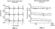
- FIG. 2 is a diagram of an example wide-band cardiac gradient signal data shown as a time series data, in accordance with an embodiment.
- the wide-band cardiac phase gradient signal data is generated as a differential of two or more of the acquired biopotential signals.
- the patient is actively driven to a common mode potential and the acquired biopotential signal includes the common mode potential.
- the wide-band cardiac gradient signal data is the remaining signal with the common-mode reference removed, e.g., via computation.
- the wide-band cardiac gradient signal data has been amplified and normalized with the common-mode reference removed.
- the acquired biopotential signal is processed via hardware circuitry to remove or normalized the applied common mode potential.
- FIG. 3 is a diagram of the example wide-band cardiac gradient signal data of FIG. 2 shown in the frequency domain, in accordance with an embodiment.
- wide-band biopotential signals having energy and frequency components beyond those of conventional electrocardiography (ECG) and traditionally perceived to be random noise, includes measurable data of the heart physiology that can be discriminated by genetic algorithms (and other machine learning algorithms) to assess regional flow characteristics of the heart, including an estimated value for stenosis an identification of ischemia, a fractional flow reserve (FFR) of specific arteries and branches thereof.
- Noise removal e.g., by applying cleaning techniques to the data resulting in the same amount of data as prior to noise removal
- the exemplified method and system processes the entire obtained biopotential signals without any noise removal operations in the wide-band region of the signal.
- noise removal that is not performed include, but not limited to, analog-based low-pass filters, band-pass filters, high-pass filters and well as digital-based filters such as FIR filters, Butterworth filters, Chebyshev filters, median filters, among others.
- certain circuit elements can introduce non-linear distortions that can affect analysis in phase space of the wide-band phase gradient signals and are not included, or minimized, in the signal path of the exemplified system.
- certain analog pass filters e.g., analog-based low-pass filters, band-pass filters, high-pass filters and well as digital-based filters such as FIR filters, Butterworth filters, Chebyshev filters, median filters, among others, as discussed above
- circuit elements such as field-effect transistors (e.g., MOSFET) may introduce unnecessary capacitance and gate-field effect noise to the signal path.
- certain semiconductor and insulating materials with avalanche breakdown effects e.g., in Zener diodes may introduce avalanche noise to the signal path.
- the signal may be processed via phase linear operations to allow for analysis of specific aspects of the high-frequency wide-band data.
- the signal may be processed via operations or circuitries that affect frequencies completely outside the band of interest. In some embodiments, these frequencies that are filtered are in the radiofrequency range or above.
- the wide-band cardiac gradient signal has a frequency component greater than about 1 kHz, which is significantly higher than convention electrocardiogram measurements.
- the wide-band cardiac gradient signal has a frequency component up to about 4 kHz (e.g., about 0 Hz to about 4 kHz).
- the wide-band cardiac gradient signal has a frequency component up to about 5 kHz (e.g., about 0 Hz to about 5 kHz).
- the wide-band cardiac gradient signal has a frequency component up to 6 kHz (e.g., about 0 Hz to about 6 kHz).
- the wide-band cardiac gradient signal has a frequency component up to about 7 kHz (e.g., about 0 Hz to about 7 kHz). In some embodiments, the wide-band cardiac gradient signal has a frequency component up to about 8 kHz (e.g., about 0 Hz to about 8 kHz). In some embodiments, the wide-band cardiac gradient signal has a frequency component up to 9 kHz (e.g., about 0 Hz to about 9 kHz). In some embodiments, the wide-band cardiac gradient signal has a frequency component up to 10 kHz (e.g., about 0 Hz to about 10 kHz). In some embodiments, the wide-band cardiac gradient signal has a frequency component up to 50 kHz (e.g., about 0 Hz to about 50 kHz).
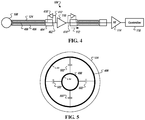
- Fig. 4 is a detailed diagram of a biosignal acquisition channel 104 in accordance with an illustrative embodiment.
- the biosignal acquisition channel 104 includes an operational amplifier 110 having an input 402 that directly couples to a terminal 404 to operatively couple to the surface electrode 106 such that little, or no, non-linear distortions (e.g., such as those discussed herein) are introduced into the signal path. To this end, active and passive filters are preferably not placed in the signal path to reduce distortions that they may be introduced during operation.
- the operational amplifier 110 preferably provides a gain greater than about 15 dB (decibel) to generate the wide-band phase gradient signal. In some embodiments, the operational amplifier 110 provides a gain greater than about 20 dB.
- the output 414 of the operational amplifier 110 in some embodiments, is coupled to the analog-to-digital conversion circuit 114 (e.g., sigma-delta ADC).
- each biosignal acquisition channel 104 electrically couples to a respective surface electrode 106 over a cable 124 (e.g., a co-axial cable and shown as cable 124a, 124b, 124c, and 124d) that employs an active noise reduction system.
- the active noise reduction system is used, in some embodiments, with the cable 124 between the surface electrode 108 and the operational amplifier 110 as well as with a cable 416 between the operational amplifier and the analog-to-digital conversion circuit 114 where such circuits are located on different circuit board.
- the biosignal acquisition channel 104 include an active noise reduction system that actively shields the signal-carrying conductor 408 in the cable 124 between the surface electrode 108 and the operational amplifier 110.
- the cable 124 includes a first conductor 408 (i.e., the signal-carrying conductor 408) that, in some embodiments, is a pair of twisted wires and a second conductive layer 406 that surrounds the conductor 408.
- the active noise reduction system includes a shield-equalizing circuit comprising an operational amplifier 410 that injects the signal carried in the conductor 408 to the shield 406 of the cable 124 such that the injected signal approximately matches (e.g., within at least about 90%) the signal carried in the cable.
- the active noise reduction system drives the shield 406 to about the same electric potential as the conductor 408, which reduces the electrical leakage between the conductor 408 and the shield 406.
- the operational amplifier 410 is configured as a unity gain amplifier.
- the input 412 of the operational amplifier 410 is coupled to the input of the gain amplifier 110, which is also coupled to the terminal 404.
- the output 414 of the operational amplifier 410 is coupled to the conductive layer 406 of the cable 124.
- Fig. 5 is a diagram illustrating operations of the shield-equalizing circuit in accordance with an illustrative embodiment.
- the shield conductor 406 of cable 124 surrounds the signal conductor 408 and is driven by the operational amplifier 410 to a potential that matches, or nearly matches, the signal conductor 408.
- the operational amplifier 410 drives the shield conductor 406 also to about -1.5V. Because the potential between the signal conductor 408 and shield conductor 406 matches, or nearly matches, the dielectric electric field between them is minimized. To this end, a perturbation introduced to the signal-conductor 408 by the shield-conductor 406 due to perturbation of the shield-conductor 406 from external interference is dampened.
- the exemplified system 100 includes a noise rejection system 120 that eliminates, or reduces, environmental noise currents flowing in the patient's body that might interfere with the biopotential measurement.
- the noise rejection system 120 is configured to actively drive the patient's body to a potential that shunts environmental noise currents during normal operation.
- Environmental noise may be generated from a variety of environmental sources including nearby electronics, transmission devices, and local AC power systems, among others. Any or all of these sources may generate voltages at the measurement electrodes that can render a patient's biopotential un-measurable or reduce the resolution of the measurement.
- the noise rejection system 120 is operatively coupled to a surface electrode 122 that is in electrical contact (e.g., directly or via a conductive gel or paste) with a surface of the body 108.
- the noise rejection system 120 actively drives the body 108 to a varying potential that varies between two negative potential values. It is found that driving the common mode potential of the body between two negative potential values facilitates the rejection of noise currents in the body while removing the need to use filters that may introduce non-linear distortions into the measured signals.
- a given surface electrode may be used in conjunction with gels or other coupling media or devices that can form a half-cell potential in the signal path when measuring the wide-band cardiac phase gradient signal.
- gels or other coupling media or devices that can form a half-cell potential in the signal path when measuring the wide-band cardiac phase gradient signal.
- silver chloride gel may introduce a 300 mV biased in the signal path.
- the noise rejection system 120 actively drives the body 108 to a varying potential that varies between two negative potential values such that the magnitudes of negative potential values are greater than the expected half-cell potential DC bias value associated with the surface electrodes.
- noise rejection system 120 is electrically coupled, via a cable 124e, to a common-mode electrode 122 that is placed on the body 108.
- an active noise reduction system e.g., similar to that used in the biosignal acquisition, is used to actively shield the signal-carrying conductor in the cable 124e between the common-mode surface electrode 122 and the noise rejection system 120.
- a passive shield is used in which the shield-conductor of the cable 124e is coupled to the ground plane of the system 100.
- the noise rejection system 120 includes a waveform generator and an operational amplifier.
- the waveform generator is a fixed-frequency oscillator.
- the waveform generator is a microcontroller that is electronically programmable to generate an analog output that can vary in frequency and amplitude range, e.g., based on control signals outputted from the controller 118.
- the noise rejection system 120 is shown operatively coupled to the controller 118 via control line 126.
- the noise rejection system 120 actively drives the body 108 to a varying potential that varies between a negative potential value and a positive potential value.
- the noise reduction system 120 actively drives the body 108 to a varying potential that varies between two positive potential values.
- the noise reduction system 120 actively drives the body to a constant potential (e.g., a value between about -1.5 V DC and about +1.5 V DC or a value between about -3.0 V DC and about +3 V DC ).
- a constant potential e.g., a value between about -1.5 V DC and about +1.5 V DC or a value between about -3.0 V DC and about +3 V DC ).
- Fig. 6 is a diagram of an example system 100 in accordance with an illustrative embodiment.
- the system 100 includes a first stage mixed-signal board 602 that includes the biosignal acquisition channel 104 as described in relation to Fig. 1 .
- the first stage mixed-signal board 602 is operatively coupled to a second stage mixed-signal board 604 over one or more cables 606 that carries the amplified biopotential signals 112.
- the second stage mixed-signal board 604 includes the analog-to-digital conversion circuit 114 and a microcontroller 118, as described in relation to Fig. 1 .
- the second stage mixed-signal board 604 communicates to a third stage controller board 606 that provides communication and interface functionality.
- the second stage mixed-signal board 604 includes memory 608 and interface circuit 610.
- the memory 608 locally stores the acquired biopotential signal data 116 associated with the wide-band cardiac phase gradient signal data for a given measurement prior to the data 116 being sent to the third stage controller board 606 to be transmitted to remote storage.
- the interface circuit 610 includes communication isolation circuitries such as optical isolators and other isolation circuitries such as, but not limited to, for power and ground.
- the third stage controller board 606 includes a processor 612, a memory 614, a communication transceiver 616, and an interface circuit 618 that, collectively, is configured to operate with the second stage mix-signal board 604 to offload the wide-band cardiac phase gradient signal data 116 acquired thereat to transmit, e.g., via wireless communication to remote storage (e.g., repositories in the cloud).
- the third stage controller board 606 is configured to analyze the wide-band cardiac phase gradient signal data acquired thereat and present outputs of the analysis at a graphical user interface associated therewith.
- the third stage controller board 606 is a part of a custom computing device. In other embodiments, the third stage controller board 606 a part of a general computing device.
- a wide-band cardiac phase gradient signal acquisition system that includes integrated surface electrodes and amplifier circuits is disclosed.
- the amplifier circuit By positioning the amplifier circuit closer to the point of signal acquisition at the surface electrode, higher signal quality can be attained because the signal path between the surface electrode and the amplifier circuit in which interference may be introduced is reduced, if not removed.
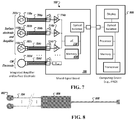
- Figs. 7 and 8 are diagrams of a wide-band cardiac phase gradient signal acquisition system 100 with an integrated surface electrode and amplifier circuit in accordance with an illustrative embodiment.
- the operational amplifier 110 (shown as amplifier 110a, 110b, and 110c) is positioned on a circuit board or flexible circuit that is housed within surface electrode housing 702 (shown as surface electrode housing elements 702a, 702b, and 702c).
- inputs 402 see, e.g., Fig. 4
- the output 412 see, e.g., Fig.
- the operational amplifier 110 is coupled, via cable 704 (shown as cables 704a, 704b, 704c), to the analog-to-digital conversion circuit 114 (shown as ADC circuits 114a, 114b, and 114c).
- an active noise reduction system e.g., similar to that described in relation to Fig. 1 , is used to actively shield the signal-carrying conductor in the cable 704 between the operational amplifier 110 and the analog-to-digital conversion circuit 114.
- a passive shield is used in which the shield-conductor of the cable 704a-704c is coupled to the ground plane of the system 100.
- the analog-to-digital conversion circuit 114 is positioned on a mixed-signal board 706 that also includes the microcontroller 118 and memory 608 that, collectively, aggregates the acquired biopotential signal data associated with the wide-band cardiac phase gradient signal and provides the data to a control board 606 to offload to remote storage.
- the integrated surface electrodes and amplifier circuits are positioned and encapsulated in a snap button housing 802 for a given acquisition channel.
- the snap button housing 802 is about 3 ⁇ 4 inch in diameter. In other embodiments, snap button housing 802 may have different diameters.
- the output 804 of the amplifier circuit in some embodiments, is a differential analog output signal that is coupled to a second housing 806 that encapsulates a mixed-signal circuit board that includes the analog-to-digital conversion circuit 114.
- the cable 704 between the snap button housing 802 and the second housing 806 is about 4 feet long, in some embodiments, and includes 4 conductors, including a first pair of twisted conductors for power and a second pair of twisted conductor to carry the analog output signal of the amplifier circuit.
- the second housing 806 may measure about 1 inch by 2.5 inch in dimensions, in some embodiments.
- the output of the second housing 806 is a second cable 808 that connects to a computing device.
- the second cable is about 2 feet long, in some embodiments, and includes 4 conductors including a power conductor, a ground conductor, and high speed digital conductors for the data lines. It should be appreciated that other dimensions of the various housing and lengths of the various cables may be used.
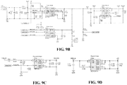
- Figs. 9A-9V comprising Figs. 9A , 9B, 9C, 9D , 9E , 9F , 9G , 9H, 9I, 9J, 9K , 9L, 9M, 9N , 9O , 9P , 9Q , 9R, 9S, 9T, 9U, and 9V , are circuit diagrams of a wide-band cardiac phase gradient signal acquisition system in accordance with an illustrative embodiment.
- Fig. 9A shows a high-level diagram of the system 100.
- the system 100 includes a main controller 118 that couples to a biopotential acquisition circuit 902 that acquires the biopotential signal data associated with wide-band cardiac phase gradient signals and a pulse oximetry circuit 904 that acquires oximetry data.
- the system 100 further includes a USB interface circuit 906 configured to provide communication to the main controller 118 for testing and development and a MFi interface circuit 908 that provides connectivity to a computing device (e.g., device 606 as described in relation to Fig. 6 ).
- the system 100 further includes a power system to provide power to the various circuits and also to provide reference voltage for the analog-to-digital conversion.
- Figs. 9B, 9C, and 9D show detailed diagrams of power circuits.
- a power circuit to supply power to the system 100 from batteries is shown.
- the power circuit includes a monitoring and charging circuit.
- Fig. 9C a power circuit for the biosignal acquisition channel is shown.
- Fig. 9D a power circuit for digital circuits is shown.
- Fig. 9E shows a detailed diagram of a controller circuit corresponding to the microcontroller 118, the controller circuit include a microcontroller 910 (shown as device “EFM32GG880” 910) and a memory 912 (shown as device “S23ML0G1” 912).
- the microcontroller "EFM32GG880” is an ARM Cortex CPU platform manufactured by Silicon Labs (Austin, TX).
- the memory "S23ML0G1” is an 8 GB (gigabyte) NAND Flash memory manufactured by Cypress Semiconductor Corporation (San Jose, CA).
- the microcontroller operates with the biosignal acquisition channel to receive the biopotential signal data acquired thereat and to locally store the data to the NAND Flash memory for each acquisition.
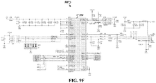
- Fig. 9F shows a detailed diagram of the MFi circuit 908 that includes a microcontroller 914 (shown as device "SiM3U167" 914) that provides an interface to an external computing device.
- the microcontroller 910 of Fig. 9E between acquisition of one or more wide-band cardiac phase gradient signal data, retrieves the data (e.g., biosignal data and instrument identification data) stored in the NAND Flash memory and transfers the data to the external computing device through the MFi circuit 908.
- data e.g., biosignal data and instrument identification data
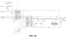
- Fig. 9G shows a detailed diagram of the USB communication circuit that is used to access the microcontroller 118 (e.g., for testing and development) and that is not available for access by a user during normal runtime operation.
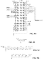
- Figs. 9H, 9I, 9J, and 9K show detailed diagrams of an analog-to-digital conversion circuit that includes an analog-to-digital converter 916 with an integrated ECG front end circuit (shown as device "ADS 1294" 916).
- Fig. 9H shows the wiring of the analog-to-digital conversion circuit 916, via the control lines and data lines, with the microcontroller 118 and the biopotential amplifier circuit shown in Fig. 9L .
- Figs. 9I, 9J, and 9K each shows the detailed diagram of the capacitive decoupling and filtering of the power plane and ground plane of the analog-to-digital conversion circuit.
- the analog-to-digital converter comprises an 8-channel, simultaneous sampling, 24-bit, delta-sigma ( ⁇ ) analog-to-digital converters (ADCs) with built-in programmable gain amplifiers (PGAs), internal reference, and an onboard oscillator.
- ADCs analog-to-digital converters
- PGAs programmable gain amplifiers
- Figs. 9L, 9M, and 9N show a detailed diagram of a biopotential acquisition circuit.
- a noise reduction circuit 918 shown as “Common Mode Drive 918” that provides a common-mode reference to the body
- a sine injection circuit 920 shown as “Sine Injection 920”
- a biopotential amplifier circuit 922 shown as “biopotential amplifiers” 922a to 922f
- the biopotential amplifier circuit 922 is coupled to a terminal 924 (shown as "J500 924”) that connects to pins of the cable 124.
- an active noise reduction system that actively shields the signal-carrying conductor in the cable 124 is used in which the shield of the cable is driven to a potential that is an average of the biopotential signal (shown as "ECG_IN_1" 926a, "ECG_IN_2" 926b, “ECG_IN_3” 926c, “ECG_IN_4" 926d, "ECG_IN_5" 926e, and “ECG_IN_6” 926f) received at each biopotential amplifier circuit 922.
- the biopotential signal shown as "ECG_IN_1" 926a, "ECG_IN_2" 926b, “ECG_IN_3” 926c, “ECG_IN_4" 926d, "ECG_IN_5" 926e, and “ECG_IN_6” 926f
- a shield-equalizing circuit may be used that includes an operational amplifier that injects the signal carried in the conductor (e.g., biopotential signals 926) to individual shields of the cable such that the injected signal approximately matches (e.g., within at least about 90%) the signal carried in the cable.
- an operational amplifier that injects the signal carried in the conductor (e.g., biopotential signals 926) to individual shields of the cable such that the injected signal approximately matches (e.g., within at least about 90%) the signal carried in the cable.
- Fig. 9M and Fig. 9N show detailed diagrams of power conditioning circuits that provide reference voltages to the biopotential amplifier circuits as shown in Fig. 9L and to the biopotential amplifier circuit as shown in Fig. 9H .
- Fig. 9O shows a detailed diagram of an example biosignal acquisition channel 922, as shown in connection with Fig. 9L , used to acquire the biopotential signals associated with the wide-band cardiac phase gradient signal.
- the example BSA instrument acquires measurements from each of the, for example, six, biopotential electrodes on the patient. Each of these voltages is measured relative to a +1.5VDC reference - the same voltage to which the patient's body is driven by the common mode amplifier during normal operation.
- An operational amplifiers U1A (shown as "LMP2022" 920) and U1B (shown as "MPL2022" 922) are powered by a single +3VDC supply. In some embodiments, a single negative -3 VDC supply is used to provide a negative DC common mode output.
- the reference common mode potential can be drive between +1.5VDC and -1.5VDC, in some embodiments.
- a negative voltage e.g., -0.5VDC
- the gain and the dynamic range of the signal can be expanded when the negative voltage exceeds the DC half-cell potential generated by the surface electrode (e.g., silver chloride electrode).
- the DC half-cell potential is about 300 mV.
- the operational amplifiers U1A 920 directly couples to the terminal 924 ( Fig. 9L ).
- a ferrite choke 928 e.g., ferrite bead
- high frequency noise e.g., radio-frequency noise
- radio-frequency signals are generally in the MHz range which is several orders of magnitude higher than the biopotential signals of interest, which are in the KHz to hundreds of KHz.
- the ferrite choke 928 has an impedance of about 1 k ⁇ .
- amplifier U1A 920 along with resistors R2 and R1, provides a gain of 101.
- a 1 mV (millivolt) peak-to-peak signal on the non-inverting input of U1A 920 translates to 101 mV peak-to-peak at the output of the amplifier 920.
- other gains can be utilized that provides at least about 15 dB. In some embodiments, the gain is greater than about 20 dB.
- the outputs 928 of all six biopotential amplifiers feed a six-channel, simultaneous sampling ADC (as shown in relation to Fig. 9H ).
- the use of a simultaneous sampling ADC minimizes the temporal skew between the biopotential channels.
- the ADC circuit 916 samples with a resolution of at least about 17 bits (e.g., about 24 bits) over an input range of about 0 V to about 5V. When combined with the input amplifier gain of 101, this provides an overall measurement resolution of about 0.38uV.
- the ADC circuit is configured to oversample at eight times the base sampling frequency, or about 8 kSPS, and to average, in computation, the results to provide additional filtering.
- the ADC circuit 916 includes internal anti-aliasing filter, e.g., at about 2.7 kHz that prevents aliasing at the full sampling rate of about 8 kSPS, in the absence of external filtering.
- the anti-aliasing filter is implemented via processing of the time series data during the analysis of the acquired biopotential signals.
- Fig. 9P shows a detailed diagram of an example noise rejection circuit that provides a common-mode reference to the body.
- the goal of the noise rejection system is to eliminate environmental noise currents flowing in the patient's body that might interfere with biopotential measurement.
- Noise may be generated from a variety of environmental sources; including consumer electronics, cell phones, and the local AC power system. Any or all of these may generate voltages at the measurement electrodes that will render a patient's biopotential un-measurable or more difficult to measure.
- the BSA Instrument hardware employs a common mode amplifier -- operational amplifier, U501B (shown as "LMP2022" 924) -- to actively drive the patient's body to a varying potential (e.g., between -1.0VDC and -2.0VDC or +1.0 and +2.0 VDC) or a constant potential (e.g., a value between +1.5 VDC or -1.5VDC) and thus shunt environmental noise currents during normal operation.
- the inverting terminal of U501A (shown as "LMP2022” 926) receives an analog signal, e.g., from the microcontroller 118 as shown in Fig.
- VCM_REF 930 that provides a reference potential
- U501B shown as “LMP2022 932”
- Capacitor C500 limits the gain of the amplifier at high frequencies, thus stabilizing its operation.
- VCM_REF 930 is, e.g., set to a constant positive +1.5VDC or negative -1.5VDC by the BSA Instrument microcontroller 118. However, this voltage can be modulated by the microcontroller in order to provide additional information regarding lead connectivity. Changes in VCM_REF will appear directly on the individual channel amplifier outputs if the reference lead and the channel leads are connected to the patient.
- Fig. 9Q shows a detailed diagram of an example sine injection circuit 920 (as also shown in relation to Fig. 9L ) used for impedance measurement.
- the sine injection circuit 920 includes a transconductance amplifier circuit (shown as "U503 934") used to inject current into a patient for thoracic impedance measurement.
- the transconductance amplifier circuit includes an operational amplifier that injects a programmable current into a Z-axis of the patient which in turn induces a voltage on the other four biopotential electrodes that can be used to derive a multi-axis impedance computation for the patient's body.
- the microcontroller 118 is configured to generate a current waveform that is offset by the reference voltage (V_Ref) generated by the noise reduction circuit.
- resistor R507 sets the transconductance gain of the amplifier to 1uA/V (micro-Amp per Volt), and resistors R504, R505, and R509 complete the feedback network.
- Capacitor C502 is available, in some embodiments, for high frequency filtering.
- Relay K500 is employed to connect the current injection circuit to the patient only when it is to be used, when the microcontroller sets the SINE_ON signal to positive +3V.
- the sine injection circuit 920 generates a frequency between about 1 kHz and about 3 kHz and have a maximum amplitude of about 100 ⁇ A.
- the sine injection circuit in some embodiments, is configured to generate a waveform for a duration of at least about 5 seconds. Other waveform and frequency may be used to determine thoracic impedance.
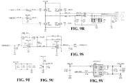
- Fig. 9R-9V comprising Figs. 9R, 9S, 9T, 9U, and 9V , are detailed diagrams of the oximetry circuit.
- the oximetry circuit is configured to operate with a pulse oximeter (PO2) sensor to collect oxygen saturation readings.
- PO2 pulse oximeter
- the oxygen saturation readings is collected with at least 12 bits of resolution and at a minimum rate of 200 samples per second.
- the noise reduction circuit of the example BSA instrument is designed to sustain the application of external defibrillation to the patient.
- resistor R524 works with Zener diode, D500, to prevent U501B from sustaining damage during external defibrillation.
- the defibrillation protection circuit in the individual channel amplifiers (e.g. Fig. 9O ), includes a fast air gap relay that adds little, or no, distortions to the connected signal path and that can survive multiple defibrillator shocks with little, or no, device degradation.
- a combined defibrillation, surge, and ESD protector circuit is used.
- An example combined defibrillation, surge, and ESD protector circuit is the MAX30031 protection devices, manufactured by Maxim Integrated (San Jose, CA).
- Fig. 10 is a photograph of an example biosignal acquisition (“BSA") board 1000 that includes the wide-band cardiac phase gradient signal acquisition system of Fig. 9 in accordance with an embodiment.
- the BSA board 1000 comprises a conductive shield 1002 that surrounds the mixed-signal circuitries of the biosignal acquisition channel and the analog-to-digital conversion circuits.
- the inputs and outputs of the BSA board 1000 are combined in a connector 1004 to the cable 124 that connects to the surface electrodes.
- the BSA board 1000 is connected to a battery 1006 that provides power to the acquisition circuit.
- the BSA board 1000 includes a USB connector 1008 that provides an interface to the microcontroller 118.
- Fig. 11 is a photograph of an example BSA instrument 1100 that includes the BSA board of Fig. 10 in accordance with an embodiment.
- the BSA system includes a housing 1102 that houses a computing device 1104 (e.g., a portable computing device) that interfaces with the BSA board 1000 (see Fig. 10 ).
- the housing 1102 includes the connector 1004 that connects to the cable 124 associated with the surface electrodes (shown as 106a, 106b, 106c, 106d, 106e, 106f, and 106g).
- surface electrodes 106a-106f are used for the acquisition of the wide-band cardiac phase gradient signals and surface electrode 106g is the common-mode reference electrode.
- Fig. 12 comprising Figs. 12A, 12B , 12C, 12D , 12E, and 12F , are example biopotential signal data 116 acquired via the example BSA instrument as shown and described in relation to Fig. 10 .
- the biopotential signal data 116 is shown normalized as time series data and with the common mode potential removed.
- Fig. 13 comprising Figs. 13A, 13B, and 13C , show as an example wide-band cardiac phase gradient signal data generated from the acquired biopotential signal data 116 of
- Fig. 12 As shown in Fig. 13 , the maximum potential of interest is only about a milli-Volt or less with an amplification of 101.
- the wide-band cardiac phase gradient signal data are generated as differentials of the acquired biopotential signal data.
- Fig. 13A a differential of channel 1 and channel 2 is shown.
- Fig. 13B a differential of channel 3 and 4 is shown.
- Fig. 13C a differential of channel 5 and 6 is shown.
- Phase gradient signals are generated from two or more biopotential signals acquired from the body, for example, as a differential between two biopotential signals acquired at two locations on the body.
- phase gradient signals can be generated for any given pairing of biopotential signals acquired at various electrodes, in addition to those shown herein, for subsequent analysis in phase space.
- Fig. 14 illustrates an example wide-band cardiac phase gradient signal of Fig. 13 presented in phase space. As shown, each of the axes (shown as "X”, “Y”, and “Z") corresponds to wide-band cardiac phase gradient signal shown in Figs. 13A, 13B, and 13C .
- non-linear phase distortions can generate errors in the differential signals, e.g., shown in Figs. 13A, 13B, and 13C , which shows as non-linear noise in the data in phase space ( Fig. 14 ).
- acquisition of wide-band phase gradient signals without non-linear phase distortions can significantly improve the accuracy and precision of subsequent analysis of the wide-band phase gradient signals in phase space.
- phase space techniques and analyses that can be performed on the wide-band cardiac phase gradient signal are described in above-referenced U.S. Provisional Appl. No. 62/354668 ; U.S. Application No. 15/192,639 , title "Methods and Systems Using Mathematical Analysis and Machine Learning to Diagnose Disease”; U.S. Publication No. 2015/0216426 ; U.S. Publication No. 2015/0133803 ; U.S. Patent No. 8,923,958 ; U.S. Patent No. 9,289,150 , and U.S. Patent No. 9,408,543 .
- the wide-band phase gradient signal data generated by the exemplified embodiments may be used, as noted above, as inputs for various phase space techniques and analyses that may in turn be used and performed to generate clinically useful information for assessing the state of the patient's health as well as to, e.g., pinpoint and distinguish disease states and their status as well as for predicting possible disease onset, whether it be in the cardiac or brain fields (such as when wide-band cardiac or cerebral phase gradient signals are used), the oncological field, the prenatal field, or any other medical field in which all or a portion of full spectrum of physiologic signals emitted from the human or other mammalian body could be so used.
- Such clinically useful information may be then further analyzed and transformed into any number of reports, data sets, presentations, etc. (in any number of formats including but not limited to digital formats for presentation via a smartphone or computer, paper report formats, presentation slide formats, or other) for review by a physician and/or presentation to a patient.
- Such data may be used, for example, by the physician to recommend further testing and/or treatment for the patient.
- Examples of methods and systems that could be used to collect and process physiologic signals as discussed herein may be found in co-owned and above-referenced U.S. Provisional Patent Application Serial No. 62/340,410 filed May 23, 2016 and entitled "Method and System for Collecting Phase Signals for Phase Space Tomography Analysis'.
- the present embodiments contemplate methods and systems for utilizing the biosignal acquisition instruments described herein to acquire and process any type of mammalian physiological signal into wide-band phase gradient signal data that may be then further processed using various phase space techniques and analyses described herein and for in turn generating data and/or reports based on such techniques and analyses, in any number of formats, that include clinically relevant and useful information for the patient and his/her physician.
- Fig. 15 is a diagram of an example placement of the surface electrodes 106a-106g at the chest and back of a patient to acquire bio-potential signals associated with wide-band cardiac phase gradient signals in accordance with an illustrative embodiment.
- Fig. 15A shows a side view of placement of the surface electrodes 106a-106g to the chest and back of the patient.
- Fig. 15B shows a front view of placement of the surface electrodes 106a-106g to the same.
- the surface electrodes are positioned at i) a first location proximal to a Right anterior axillary line corresponding to a 5th intercostal space; ii) a second location proximal to a Left anterior axillary line corresponding to the 5th intercostal space; iii) a third location proximal to a Left sternal border corresponding to a 1st intercostal space; iv) a fourth location proximal to the Left sternal border below the sternum and lateral to a xiphoid process; v) a fifth location proximal to the Left sternal border corresponding to a 3rd intercostal space; vi) a sixth location proximal to a Back directly opposite of the fifth location and left of a spine; and viii) a seventh location proximal to a Right upper quadrant corresponding to a 2nd intercostal space along a Left axillary line.
- the exemplified system 100 may be used to acquire wide-band cerebral phase gradient signals.
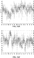
- Fig. 16 comprising Figs. 16A, 16B , 16C, 16D , 16E, and 16F , are example biopotential signal data 116 acquired from a head of a patient via the example BSA Instrument as shown and described in relation to Fig. 9 .
- the biopotential signal data 116 is shown normalized as time series data and with the common mode potential removed.
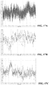
- Fig. 17 shows an example wide-band cerebral phase gradient signal data generated from the acquired biopotential signal data 116 of Fig. 16 .
- the wide-band cerebral phase gradient signal data are generated as differentials of the acquired biopotential signal data.
- Fig. 17A a differential of channel 1 and channel 2 is shown.
- Fig. 17B a differential of channel 3 and 4 is shown.
- Fig. 17C a differential of channel 5 and 6 is shown.
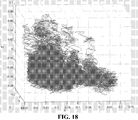
- Fig. 18 illustrates an example wide-band cerebral phase gradient signal of Fig. 17 presented in phase space. As shown, each of the axes (shown as “X”, “Y”, and “Z") corresponds to wide-band cerebral phase gradient signal shown in Figs. 18A, 18B, and 18C .
- Fig. 19 is a diagram of an example placement of the surface electrodes at the head and neck of a patient to acquire biopotential signals associated with wide-band cerebral phase gradient signals in accordance with an illustrative embodiment.
- Fig. 19A shows a front view of placement of the surface electrodes 106a-106g to the patient.
- Fig. 19B and Fig. 19C shows side views of placement of the surface electrodes 106a-106g to the same.
- a first set of two surface electrodes (shown as 1902 and 1904) corresponding to a first differential channel is placed at the left and right temple, a second set of two surface electrodes (shown as 1906 and 1908) corresponding to a second differential channel is placed under each ear, and a third set of two surface electrodes (shown as 1910 and 1912) corresponding to a third differential channel is placed at the back of each side of the neck.
- a seventh surface electrode (shown as 1914) corresponding to common-mode potential output of the system 100 is shown placed at the center.
- Fig. 20 is an example operation of BSA instrument or device 1100 in accordance with an illustrative embodiment.
- the BSA instrument 1100 is configured to acquire a wide-band cardiac phase gradient signal 116 from a patient 108.
- Each BSA instrument 1100 is operatively coupled a wireless communication device 2002 that is configured to transmit the acquired wide-band cardiac phase gradient signal data 116 to a data repository 2004 (shown as "MDDS 2004" (Medical Device Data System)) that is connected to a plurality of BSA instrument 100.
- MDDS 2004 Medical Device Data System
- the wide-band cardiac phase gradient signal data 116 of each BSA instrument 1100 is stored at the repository 2004 and is subsequently analyzed, e.g., by a processing center 2006.
- the output of the analysis is stored in a diagnosis repository 2008 that is accessible to clinicians, via client devices 2010, from a portal 2012 operatively coupled to the diagnosis repository 2008.
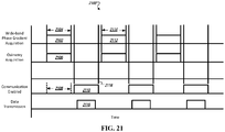
- Fig. 21 is a diagram of a method 2100 of operating the BSA instrument 1100 to reduce interference from self-transmission in accordance with an illustrative embodiment.
- the BSA instrument 1100 is configured to coordinate the transmission of the acquired data and the acquisition of the wide-band cardiac phase gradient signal to prevent, or reduce, interference from the wireless communication circuits associated with the BSA instrument 1100.
- acquisition 2102 of biopotential signals associated the wide-band cardiac phase gradient signal is performed at time 2104.
- the oximetry measurements 2106 is made concurrently with the same time period.
- the BSA instrument 1100 is configured to disable the wireless transmitter of the BSA instrument 1100. As shown in Fig. 21 , during the time period 2104, the wireless transmitter of the BSA instrument 1100 is disabled (i.e., de-energized) as shown in 2108. After the wide-band cardiac phase gradient signal 2102 has been acquired and stored, the wireless transmitter 2110 of the BSA instrument 1100 is enabled. Prior to the next wide-band cardiac phase gradient signal acquisition 2112 (shown as time period 2114), the previously acquired wide-band cardiac phase gradient signal 2102 is transmitted in data transmission 2116 to a repository. Once transmission 2116 is completed, the wireless transmitter of the BSA instrument 1100 is disabled at time 2118.
- acquisition of biopotential signals associated with wide-band phase gradient signals may be performed at other parts of the body to diagnose various disease and conditions.
- the exemplified system may be used to acquire biopotential signals associated with wide-band phase gradient signals for oncology.
- the exemplified system may be used to acquire biopotential signals associated with wide-band phase gradient signals for monitoring pre-natal development.
- the exemplified methods and systems can be used to acquire biosignals from any type of mammals and animals including test animals for research and clinical purposes as well as for the treatment of animals in veterinary purposes.
Landscapes
- Health & Medical Sciences (AREA)
- Life Sciences & Earth Sciences (AREA)
- Engineering & Computer Science (AREA)
- Physics & Mathematics (AREA)
- General Health & Medical Sciences (AREA)
- Pathology (AREA)
- Biomedical Technology (AREA)
- Heart & Thoracic Surgery (AREA)
- Medical Informatics (AREA)
- Molecular Biology (AREA)
- Surgery (AREA)
- Animal Behavior & Ethology (AREA)
- Biophysics (AREA)
- Public Health (AREA)
- Veterinary Medicine (AREA)
- Cardiology (AREA)
- Physiology (AREA)
- Signal Processing (AREA)
- Optics & Photonics (AREA)
- Computer Networks & Wireless Communication (AREA)
- Artificial Intelligence (AREA)
- Computer Vision & Pattern Recognition (AREA)
- Psychiatry (AREA)
- Spectroscopy & Molecular Physics (AREA)
- Power Engineering (AREA)
- Measurement And Recording Of Electrical Phenomena And Electrical Characteristics Of The Living Body (AREA)
Claims (14)
- Vorrichtung (100), umfassend:zwei oder mehr Biosignal-Erfassungskanäle (104), wobei jeder Biosignal-Erfassungskanal (104) einen Verstärker (110) umfasst, der konfiguriert ist, um Biopotentialsignale zu verstärken, die von einer zugeordneten Oberflächenelektrode (106) empfangen werden, die an einem Patienten zu platzieren ist; undeine Analog-Digital-Umwandlungsschaltung (114), die dazu konfiguriert ist, jede Ausgabe der zwei oder mehr Biosignal-Erfassungskanäle (104) zu empfangen und jeden der zwei oder mehr Biosignal-Erfassungskanäle (104) gleichzeitig abzutasten, um einen breitbandigen Herzphasengradientensignal-Datenstrom mit einer Frequenzkomponente von mehr als 1 kHz zu erzeugen,wobei jedes Biopotentialsignal ohne Filterung verstärkt wird, die eine Verzerrung in dem erzeugten breitbandigen Herzphasengradientensignal über 1 kHz verursacht.
- Vorrichtung (100) nach Anspruch 1, umfassend:
eine Potentialvorspannungsschaltung, die dazu konfiguriert ist, den Patienten aktiv auf ein variierendes oder konstantes Potential zu treiben, um im Patienten fließende Umgebungsgeräuschströme zu überbrücken. - Vorrichtung (100) nach Anspruch 1, umfassend:einen Anschlussblock, der eine Vielzahl von Verbindern umfasst, die konfiguriert sind, um ein Kabel zu koppeln, das einer gegebenen Oberflächenelektrode zugeordnet ist, wobei das Kabel eine Abschirmungsschicht umfasst, die einen oder mehrere Signaldrähte einkapselt, die konfiguriert sind, um ein gegebenes Biopotentialsignal zu übertragen, das von der gegebenen Oberflächenelektrode empfangen wird; undeine Rauschunterdrückungsschaltung mit einem Eingang, der dazu konfiguriert ist, das Biopotentialsignal (112) zu empfangen, das über eine oder mehrere Signalleitungen (408) übertragen wird, und einem Ausgang, der konfiguriert ist, um mit einem Verbinder einer Vielzahl von Verbindern verbunden zu werden, die einer Abschirmungsschicht (406) für ein gegebenes Kabel (124) zugeordnet sind,wobei die Rauschunterdrückungsschaltung so konfiguriert ist, um Rauschinterferenz über das Kabel (124) zurückzuweisen, indem die empfangene Bedrohung des Biopotentialsignals (112) über die Abschirmungsschicht (406) geleitet wird.
- Vorrichtung (100) nach Anspruch 1, umfassend:einen oder mehrere Anschlussblöcke, von denen jeder so konfiguriert ist, dass er individuell mit einer Abschirmung (406) eines Kabels (124) verbunden ist, das einer Oberflächenelektrode zugeordnet ist; undeine Abschirmungsausgleichsschaltung, die dazu konfiguriert ist, ein in dem Kabel (124) getragenes Signal in die Abschirmung (406) des Kabels (124) einzuspeisen, wobei das eingespeiste Signal ungefähr mit dem im Kabel (124) getragenen Signal übereinstimmt.
- Vorrichtung (100) nach einem der Ansprüche 1 bis 4, wobei der Verstärker (110) von jedem der zwei oder mehr Biosignal-Erfassungskanäle (104) konfiguriert ist, um direkt mit einem Anschlussblock gekoppelt zu werden, der Folgendes umfasst: eine Vielzahl von Anschlüssen, wobei jeder Verbinder konfiguriert ist, um ein Kabel (124) zu koppeln, das einer gegebenen Oberflächenelektrode (106) zugeordnet ist.
- Vorrichtung (100) nach einem der Ansprüche 1 bis 5, wobei jeder der zwei oder mehr Biosignal-Erfassungskanäle (104) Folgendes umfasst:
ein Tiefpass-Antialiasing-Filter, das konfiguriert ist, um unterhalb einer Nyquist-Frequenz einer Betriebsabtastfrequenz der Analog-Digital-Schaltung (114) zu filtern. - Vorrichtung (100) nach einem der Ansprüche 1 bis 6, wobei jeder der zwei oder mehr Biosignal-Erfassungskanäle (104) Folgendes umfasst:
einen Verstärker (110), der konfiguriert ist, um das empfangene Biopotentialsignal mit einer Verstärkung zu verstärken, die eine Messauflösung mit der Analog-Digital-Schaltung (114) von mehr als 0,3 µV pro Bit bereitstellt. - Vorrichtung (100) nach einem der Ansprüche 1 bis 7, wobei die zwei oder mehr Biopotentialkanäle (104) eine Anzahl von Kanälen umfassen, ausgewählt aus der Gruppe bestehend aus 2, 3, 4, 5, 6, 7, 8, 9, 10, 11 und 12.
- Vorrichtung (100) nach einem der Ansprüche 1 bis 8, wobei die Analog-Digital-Schaltung (114) jedes Biosignal-Erfassungskanals (104) konfiguriert ist, um ein breitbandiges Herzphasengradientensignal über einen vordefinierten Spannungsbereich von mindestens 5 mV bei einer Auflösung von weniger als 2 µV pro Bit und einer Rate von mehr als 5 KHz abzutasten, wobei die zwei oder mehr Biosignal-Erfassungskanäle (104) konfiguriert sind, um gleichzeitig mit einem zeitlichen Versatz zwischen Kanälen von weniger als 1 µs abgetastet zu werden, und wobei jeder Biosignal-Erfassungskanal (104) ein Signal-Rausch-Verhältnis von mehr als 15 dB umfasst.
- Vorrichtung (100) nach Anspruch 1, umfassend eine Defibrillationsschutzschaltung mit einem Schaltelement, das konfiguriert ist, um dem Signalpfad der zwei oder mehr Biosignal-Erfassungskanäle (104) kein thermisches Rauschen oder Lawinenrauschen hinzuzufügen.
- Vorrichtung (100) nach Anspruch 10, wobei die Defibrillationsschutzschaltung ferner einen Nebenschlussinduktor umfasst, der konfiguriert ist, um mit einem Nebenschlusswiderstand des einen oder der mehreren Nebenschlusswiderstände gekoppelt zu werden.
- Vorrichtung (100) nach einem der Ansprüche 1 bis 11, wobei jeder Biosignal-Erfassungskanal (104) eine Verstärkerschaltung (110) umfasst, die konfiguriert ist, um direkt an eine gegebene Oberflächenelektrode (106) innerhalb eines Elektrodengehäuses zu koppeln.
- Vorrichtung (100) nach Anspruch 1, umfassend:zwei oder mehr Analog-Digital-Schaltungen (114), die jeweils den zwei oder mehr Biosignal-Erfassungskanälen (104) entsprechen, wobei die zwei oder mehr Biosignal-Erfassungskanäle (104) konfiguriert sind, um jede Ausgabe der zwei oder mehr Biosignal-Erfassungskanäle (104) einer entsprechenden Analog-Digital-Schaltung (114) der zwei oder mehr Analog-Digital-Schaltungen zuzuführen, undwobei die zwei oder mehr Analog-Digital-Schaltungen (114) konfiguriert sind, um gleichzeitig jeden der zwei oder mehr Biosignal-Erfassungskanäle (104) abzutasten, um zwei oder mehr breitbandige Herzphasengradientensignal-Datenströme zu erzeugen, von denen jeder einem gegebenen Breitband-Herzphasengradientensignal zugeordnet ist.
- Verfahren zum Erzeugen breitbandiger Herzphasengradientensignal-Daten, wobei das Verfahren Folgendes umfasst:Verstärken von Biopotentialsignalen, die von einer Vielzahll von Oberflächenelektroden (106) empfangen werden, die jeweils an einem Patienten platziert sind, um ein Breitband-Herzphasengradientensignal für jedes der empfangenen Biopotentialsignale zu erzeugen, wobei jedes Biopotentialsignal ohne Filterung verstärkt wird, die Verzerrungen in dem erzeugten breitbandigen Herzphasengradientensignal über 1 kHz verursacht; undgleichzeitiges Abtasten jedes der verstärkten breitbandigen Herzphasengradientensignale (112) mit einer Abtastfrequenz von mehr als 50 kHz, um breitbandige Herzphasengradientensignal-Datenströme mit einer Frequenzkomponente von mehr als 1 kHz zu erzeugen, wobei die verstärkten breitbandigen Herzphasengradientensignale (112) gleichzeitig abgetastet werden, um einen zeitlichen Versatz zwischen jedem der verstärkten breitbandigen Herzphasengradientensignale (112) von weniger als 1 µs zu haben.
Applications Claiming Priority (5)
| Application Number | Priority Date | Filing Date | Title |
|---|---|---|---|
| US201562210427P | 2015-08-26 | 2015-08-26 | |
| US201562210426P | 2015-08-26 | 2015-08-26 | |
| US201662340410P | 2016-05-23 | 2016-05-23 | |
| US201662354668P | 2016-06-24 | 2016-06-24 | |
| PCT/IB2016/055125 WO2017033164A1 (en) | 2015-08-26 | 2016-08-26 | Method and apparatus for wide-band phase gradient signal acquisition |
Publications (4)
| Publication Number | Publication Date |
|---|---|
| EP3340872A1 EP3340872A1 (de) | 2018-07-04 |
| EP3340872A4 EP3340872A4 (de) | 2019-06-19 |
| EP3340872B1 true EP3340872B1 (de) | 2021-10-20 |
| EP3340872B8 EP3340872B8 (de) | 2021-11-24 |
Family
ID=58099747
Family Applications (1)
| Application Number | Title | Priority Date | Filing Date |
|---|---|---|---|
| EP16838658.9A Active EP3340872B8 (de) | 2015-08-26 | 2016-08-26 | Verfahren und vorrichtung zur breitbandigen phasengradientensignalerfassung |
Country Status (6)
| Country | Link |
|---|---|
| US (4) | US10542897B2 (de) |
| EP (1) | EP3340872B8 (de) |
| JP (2) | JP6920693B2 (de) |
| CN (2) | CN108471973B (de) |
| CA (1) | CA2996096A1 (de) |
| WO (1) | WO2017033164A1 (de) |
Families Citing this family (32)
| Publication number | Priority date | Publication date | Assignee | Title |
|---|---|---|---|---|
| CA2990367C (en) | 2015-06-25 | 2019-12-24 | Analytics For Life Inc. | Methods and systems using mathematical analysis and machine learning to diagnose disease |
| US9706269B2 (en) * | 2015-07-24 | 2017-07-11 | Hong Kong Applied Science and Technology Research Institute Company, Limited | Self-powered and battery-assisted CMOS wireless bio-sensing IC platform |
| CA2996096A1 (en) | 2015-08-26 | 2017-03-02 | Analytics For Life Inc. | Method and apparatus for wide-band phase gradient signal acquisition |
| JP6945204B2 (ja) | 2016-06-24 | 2021-10-06 | アナリティクス フォー ライフ インコーポレイテッド | 心筋虚血の測定、狭窄識別、位置特定、および血流予備量比推定の非侵襲性方法およびシステム |
| DE202017007628U1 (de) | 2016-07-05 | 2023-12-21 | Semiconductor Energy Laboratory Co., Ltd. | Positivelektrodenaktivmaterial und Sekundärbatterie |
| CN118000760A (zh) | 2016-09-21 | 2024-05-10 | 生命解析公司 | 用于可视化有风险的心脏组织的方法和系统 |
| USD855064S1 (en) | 2016-09-21 | 2019-07-30 | Analytics For Life Inc. | Display screen with graphical user interface |
| EP4364650B1 (de) | 2017-03-02 | 2026-04-29 | Analytics for Life Inc. | Signalerfassungskarte |
| US11062792B2 (en) | 2017-07-18 | 2021-07-13 | Analytics For Life Inc. | Discovering genomes to use in machine learning techniques |
| US11139048B2 (en) | 2017-07-18 | 2021-10-05 | Analytics For Life Inc. | Discovering novel features to use in machine learning techniques, such as machine learning techniques for diagnosing medical conditions |
| WO2019077414A1 (en) * | 2017-10-20 | 2019-04-25 | Analytics For Life Inc. | METHODS AND SYSTEMS FOR DEBRISING MAGNETIC FIELD-BASED SENSOR DATA FROM ELECTROPHYSIOLOGICAL SIGNALS |
| US11133109B2 (en) | 2017-12-29 | 2021-09-28 | Analytics For Life Inc. | Method and system to assess disease using phase space volumetric objects |
| US11918333B2 (en) | 2017-12-29 | 2024-03-05 | Analytics For Life Inc. | Method and system to assess disease using phase space tomography and machine learning |
| WO2019234587A1 (en) * | 2018-06-04 | 2019-12-12 | Analytics For Life | Method and system to assess pulmonary hypertension using phase space tomography and machine learning |
| US11147516B2 (en) | 2018-06-18 | 2021-10-19 | Analytics For Life Inc. | Methods and systems to quantify and remove asynchronous noise in biophysical signals |
| US11589829B2 (en) | 2018-12-26 | 2023-02-28 | Analytics For Life Inc. | Methods and systems to configure and use neural networks in characterizing physiological systems |
| JP7900769B2 (ja) * | 2018-12-26 | 2026-08-05 | アナリティクス フォー ライフ インコーポレイテッド | 信号品質の自動定量化のための方法及びシステム |
| JP7519045B2 (ja) | 2019-06-18 | 2024-07-19 | アナリティクス フォー ライフ インコーポレイテッド | 心臓シグナル及びフォトプレチスモグラフィシグナルの動力学的解析を使用して疾患を評価するための方法及びシステム |
| US20230172472A1 (en) * | 2019-08-28 | 2023-06-08 | Chun-Fang Cheng | Biological energy signal acquisition and conversion device |
| CN115243617B (zh) | 2019-12-23 | 2025-10-28 | 测验有限公司 | 电极贴片和连接系统 |
| WO2021130709A1 (en) | 2019-12-23 | 2021-07-01 | Analytics For Life Inc. | Method and system for signal quality assessment and rejection using heart cycle variability |
| US11571159B1 (en) * | 2020-07-23 | 2023-02-07 | Meta Platforms Technologies, Llc | Floating biopotential samplings |
| CN114081500A (zh) * | 2020-07-30 | 2022-02-25 | 京东方科技集团股份有限公司 | 信号采集电路和生理检测设备 |
| WO2022064464A1 (en) | 2020-09-25 | 2022-03-31 | Analytics For Life Inc. | Method and system to assess disease using multi-sensor signals |
| US20220133206A1 (en) * | 2020-11-03 | 2022-05-05 | Biosense Webster (Israel) Ltd. | Recording apparatus noise reduction |
| DE102020213881B4 (de) * | 2020-11-04 | 2022-06-23 | Lenze Se | Verfahren zum Übertragen von zeitlich aufeinanderfolgenden Datensätzen eines Positionsgebers über ein Ethernet-Netzwerk und elektrisches Antriebssystem |
| CA3203044A1 (en) | 2020-12-23 | 2022-06-30 | Farhad FATHIEH | Method and system for engineering cycle variability-related features from biophysical signals for use in characterizing physiological systems |
| CN118119331A (zh) | 2021-08-23 | 2024-05-31 | 生命解析公司 | 用于将来自生物物理信号的视觉特征工程化以用于表征生理系统的方法和系统 |
| US12482565B2 (en) | 2021-08-23 | 2025-11-25 | Analytics For Life Inc. | Methods and systems for engineering conduction deviation features from biophysical signals for use in characterizing physiological systems |
| WO2023026156A1 (en) | 2021-08-23 | 2023-03-02 | Analytics For Life Inc. | Methods and systems for engineering cardiac waveform features from biophysical signals for use in characterizing physiological systems |
| EP4391895A4 (de) | 2021-08-23 | 2025-10-08 | Analytics For Life Inc | Verfahren und system zur nichtinvasiven beurteilung von erhöhtem linksventrikulärem enddiastolischem druck |
| WO2025134032A1 (en) * | 2023-12-20 | 2025-06-26 | Vasanth Nitin | Method and system for electromagnetic noise detection and cancellation |
Citations (1)
| Publication number | Priority date | Publication date | Assignee | Title |
|---|---|---|---|---|
| US20030105403A1 (en) * | 2001-07-17 | 2003-06-05 | Gmp Companies, Inc. | Wireless ECG System |
Family Cites Families (46)
| Publication number | Priority date | Publication date | Assignee | Title |
|---|---|---|---|---|
| US4800495A (en) * | 1986-08-18 | 1989-01-24 | Physio-Control Corporation | Method and apparatus for processing signals used in oximetry |
| CN1012257B (zh) | 1986-09-09 | 1991-04-03 | 顾涵森 | 生物电信号检测装置 |
| US5020540A (en) * | 1987-10-09 | 1991-06-04 | Biometrak Corporation | Cardiac biopotential analysis system and method |
| US5243993A (en) | 1991-06-28 | 1993-09-14 | Life Fitness | Apparatus and method for measuring heart rate |
| JPH05220121A (ja) | 1992-01-27 | 1993-08-31 | Nec Corp | 携帯用心電図解析装置のオートドリフトキャンセル回路 |
| DE4206352A1 (de) * | 1992-02-29 | 1993-09-02 | Deutsche Aerospace | Verfahren zum linearen verstaerken eines nutzsignals und verstaerker zum durchfuehren des verfahrens |
| JP3198451B2 (ja) * | 1993-04-26 | 2001-08-13 | 日本光電工業株式会社 | 雑音除去方法及び装置 |
| US5823957A (en) | 1994-10-17 | 1998-10-20 | Biofield Corp | D.C. biopotential sensing electrode and electroconductive medium for use therein |
| US6014582A (en) * | 1996-10-23 | 2000-01-11 | He; Bin | Method and apparatus of biosignal spatial analysis |
| FR2758221B1 (fr) * | 1997-01-07 | 1999-03-26 | Ela Medical Sa | Dispositif de filtrage de signaux d'activite cardiaque |
| WO1999066637A1 (en) * | 1998-06-19 | 1999-12-23 | Datum Telegraphic Inc. | Circuit and methods for compensating for imperfections in amplification chains in a linc or other amplification system |
| US6405081B1 (en) * | 1999-04-22 | 2002-06-11 | Koninklijke Philips Electronics N.V. | Damped biphasic energy delivery circuit for a defibrillator |
| JP3415796B2 (ja) * | 2000-01-13 | 2003-06-09 | 日本コーリン株式会社 | 周期性生体情報測定装置 |
| US7811234B2 (en) * | 2002-08-01 | 2010-10-12 | California Institute Of Technology | Remote-sensing method and device |
| US7896807B2 (en) | 2004-10-29 | 2011-03-01 | Worcester Polytechnic Institute | Multi-channel electrophysiologic signal data acquisition system on an integrated circuit |
| US8185199B2 (en) | 2005-02-10 | 2012-05-22 | Zoll Medical Corporation | Monitoring physiological signals during external electrical stimulation |
| JP2007095968A (ja) | 2005-09-28 | 2007-04-12 | Matsushita Electric Ind Co Ltd | 半導体レーザー装置用ステム及びその製造方法 |
| WO2007060609A2 (en) | 2005-11-25 | 2007-05-31 | Koninklijke Philips Electronics N.V. | Biometric sensor |
| CN101951832B (zh) * | 2007-06-22 | 2013-06-12 | Cmte开发有限公司 | 头皮电势测量方法和设备 |
| JP2009066203A (ja) * | 2007-09-13 | 2009-04-02 | Terumo Corp | 生体情報測定装置及び生体情報収集システム |
| EP2339961B1 (de) * | 2008-10-09 | 2018-03-07 | The Regents of the University of California | Gerät zur automatischen lokalisation von quellen von biologischen rhythmusstörungen |
| CN101579236A (zh) | 2009-06-05 | 2009-11-18 | 大连大学 | 一种人体阻抗的多频多段测量装置及测量方法 |
| US9775531B2 (en) * | 2010-06-09 | 2017-10-03 | Techmedic Development International B.V. | Sensor device, processing device, and measurement system for acquiring a biopotential |
| EP2642916B1 (de) | 2010-11-23 | 2023-05-10 | ResMed Pty Ltd | Verfahren und vorrichtung zur erkennung von herzsignalen |
| WO2012106729A1 (en) | 2011-02-04 | 2012-08-09 | Phase Space Systems Corporation | System and method for evaluating an electrophysiological signal |
| CN102694509B (zh) * | 2011-03-22 | 2017-02-15 | 北京汉朔科技有限公司 | 具有交流激励功能的集成电生理信号放大器 |
| CN103957862B (zh) * | 2011-07-20 | 2017-02-08 | 呼吸运动公司 | 阻抗测量设备以及用于紧急心脏血管护理的方法 |
| ES2587511T3 (es) | 2012-01-27 | 2016-10-25 | Fundación Azti/Azti Fundazioa | Sistema para detectar el nivel de estrés / malestar de animales acuáticos |
| US10182732B2 (en) | 2012-02-08 | 2019-01-22 | Easyg Llc | ECG system with multi mode electrode units |
| US9251604B2 (en) | 2012-07-20 | 2016-02-02 | Samsung Electronics Co., Ltd. | Apparatus and method for generating tomography image |
| US9968265B2 (en) | 2012-08-17 | 2018-05-15 | Analytics For Life | Method and system for characterizing cardiovascular systems from single channel data |
| US9408543B1 (en) | 2012-08-17 | 2016-08-09 | Analytics For Life | Non-invasive method and system for characterizing cardiovascular systems for all-cause mortality and sudden cardiac death risk |
| US9289150B1 (en) | 2012-08-17 | 2016-03-22 | Analytics For Life | Non-invasive method and system for characterizing cardiovascular systems |
| US9737229B1 (en) | 2013-06-04 | 2017-08-22 | Analytics For Life | Noninvasive electrocardiographic method for estimating mammalian cardiac chamber size and mechanical function |
| US10039468B2 (en) | 2013-11-12 | 2018-08-07 | Analytics For Life Inc. | Noninvasive electrocardiographic method for estimating mammalian cardiac chamber size and mechanical function |
| US9597021B1 (en) | 2014-01-14 | 2017-03-21 | Analytics For Life | Noninvasive method for estimating glucose, glycosylated hemoglobin and other blood constituents |
| US20150223743A1 (en) * | 2014-02-12 | 2015-08-13 | Wipro Limited | Method for monitoring a health condition of a subject |
| US9974488B2 (en) * | 2014-06-27 | 2018-05-22 | The Regents Of The University Of Michigan | Early detection of hemodynamic decompensation using taut-string transformation |
| US20160007862A1 (en) * | 2014-07-14 | 2016-01-14 | Mediatek Inc. | Method for collecting personal health data and personal health device utilizing the same |
| CN204428029U (zh) * | 2015-02-04 | 2015-07-01 | 四川宇峰科技发展有限公司 | 全自动自主神经分析仪器 |
| EP3103391B1 (de) | 2015-05-21 | 2018-10-10 | BIOTRONIK SE & Co. KG | Implantierbare vorrichtung mit einem sauerstoffsensor |
| CA2990367C (en) | 2015-06-25 | 2019-12-24 | Analytics For Life Inc. | Methods and systems using mathematical analysis and machine learning to diagnose disease |
| CA2996096A1 (en) | 2015-08-26 | 2017-03-02 | Analytics For Life Inc. | Method and apparatus for wide-band phase gradient signal acquisition |
| JP6945204B2 (ja) | 2016-06-24 | 2021-10-06 | アナリティクス フォー ライフ インコーポレイテッド | 心筋虚血の測定、狭窄識別、位置特定、および血流予備量比推定の非侵襲性方法およびシステム |
| CN118000760A (zh) | 2016-09-21 | 2024-05-10 | 生命解析公司 | 用于可视化有风险的心脏组织的方法和系统 |
| EP4364650B1 (de) | 2017-03-02 | 2026-04-29 | Analytics for Life Inc. | Signalerfassungskarte |
-
2016
- 2016-08-26 CA CA2996096A patent/CA2996096A1/en active Pending
- 2016-08-26 JP JP2018510409A patent/JP6920693B2/ja active Active
- 2016-08-26 US US15/248,838 patent/US10542897B2/en active Active
- 2016-08-26 CN CN201680048385.6A patent/CN108471973B/zh active Active
- 2016-08-26 CN CN202110829979.3A patent/CN113693607B/zh active Active
- 2016-08-26 WO PCT/IB2016/055125 patent/WO2017033164A1/en not_active Ceased
- 2016-08-26 EP EP16838658.9A patent/EP3340872B8/de active Active
-
2020
- 2020-01-27 US US16/773,099 patent/US11395618B2/en active Active
-
2021
- 2021-01-15 US US17/150,511 patent/US12011275B2/en active Active
- 2021-07-14 JP JP2021116323A patent/JP7158668B2/ja not_active Expired - Fee Related
-
2024
- 2024-06-17 US US18/744,902 patent/US20250082245A1/en active Pending
Patent Citations (1)
| Publication number | Priority date | Publication date | Assignee | Title |
|---|---|---|---|---|
| US20030105403A1 (en) * | 2001-07-17 | 2003-06-05 | Gmp Companies, Inc. | Wireless ECG System |
Also Published As
| Publication number | Publication date |
|---|---|
| CA2996096A1 (en) | 2017-03-02 |
| US11395618B2 (en) | 2022-07-26 |
| JP2018526088A (ja) | 2018-09-13 |
| EP3340872B8 (de) | 2021-11-24 |
| EP3340872A1 (de) | 2018-07-04 |
| JP7158668B2 (ja) | 2022-10-24 |
| CN108471973A (zh) | 2018-08-31 |
| WO2017033164A1 (en) | 2017-03-02 |
| JP6920693B2 (ja) | 2021-08-18 |
| US10542897B2 (en) | 2020-01-28 |
| CN108471973B (zh) | 2021-08-10 |
| US20210128045A1 (en) | 2021-05-06 |
| JP2021168941A (ja) | 2021-10-28 |
| US20250082245A1 (en) | 2025-03-13 |
| US20200229724A1 (en) | 2020-07-23 |
| CN113693607B (zh) | 2024-10-01 |
| EP3340872A4 (de) | 2019-06-19 |
| CN113693607A (zh) | 2021-11-26 |
| US12011275B2 (en) | 2024-06-18 |
| US20170119272A1 (en) | 2017-05-04 |
Similar Documents
| Publication | Publication Date | Title |
|---|---|---|
| US20250082245A1 (en) | Method and apparatus for wide-band phase gradient signal acquisition | |
| JP7344500B2 (ja) | 広帯域位相勾配信号取得のための方法および装置 | |
| Gargiulo et al. | A mobile EEG system with dry electrodes | |
| US10729379B2 (en) | Electrical wearable capacitive biosensor and noise artifact suppression method | |
| BRPI0812854B1 (pt) | Aparelho e método de medição de potencial de tensão do couro cabeludo | |
| Jaw et al. | Modular design of a long-term portable recorder for physiological signals | |
| Guermandi et al. | EEG acquisition system based on active electrodes with common-mode interference suppression by Driving Right Leg circuit | |
| Kumaragamage et al. | Development of an ultra low noise, miniature signal conditioning device for vestibular evoked response recordings | |
| HK40110311A (en) | Method and apparatus for wide-band phase gradient signal acquisition | |
| Pratama et al. | The development of Arduino-based low-cost wireless modular device for brainwave acquisition | |
| Zafeiropoulos et al. | The neoEEG board: A 3 nV/Hz multi-channel wireless instrument for neonatal EEG monitoring | |
| Chowdhury et al. | Development of two wireless ECG monitoring systems and their performance assessment | |
| Chatterjee et al. | Non-invasive wireless EEG monitor | |
| Xu et al. | Design and optimization of ICs for wearable EEG sensors | |
| Babusiak et al. | Design and Development of a Multimodal Bioamplifier | |
| Krishnan et al. | Ultra Low Power Electrophysiological Monitoring System based on Android Platform |
Legal Events
| Date | Code | Title | Description |
|---|---|---|---|
| STAA | Information on the status of an ep patent application or granted ep patent |
Free format text: STATUS: THE INTERNATIONAL PUBLICATION HAS BEEN MADE |
|
| PUAI | Public reference made under article 153(3) epc to a published international application that has entered the european phase |
Free format text: ORIGINAL CODE: 0009012 |
|
| STAA | Information on the status of an ep patent application or granted ep patent |
Free format text: STATUS: REQUEST FOR EXAMINATION WAS MADE |
|
| 17P | Request for examination filed |
Effective date: 20180313 |
|
| AK | Designated contracting states |
Kind code of ref document: A1 Designated state(s): AL AT BE BG CH CY CZ DE DK EE ES FI FR GB GR HR HU IE IS IT LI LT LU LV MC MK MT NL NO PL PT RO RS SE SI SK SM TR |
|
| AX | Request for extension of the european patent |
Extension state: BA ME |
|
| DAV | Request for validation of the european patent (deleted) | ||
| DAX | Request for extension of the european patent (deleted) | ||
| RIC1 | Information provided on ipc code assigned before grant |
Ipc: A61B 5/0476 20060101ALN20190211BHEP Ipc: A61B 5/0428 20060101AFI20190211BHEP Ipc: A61B 5/04 20060101ALI20190211BHEP Ipc: A61B 5/0402 20060101ALI20190211BHEP Ipc: A61B 5/00 20060101ALN20190211BHEP Ipc: A61B 5/0404 20060101ALN20190211BHEP Ipc: A61B 5/0408 20060101ALN20190211BHEP Ipc: G16H 10/00 20180101ALI20190211BHEP |
|
| A4 | Supplementary search report drawn up and despatched |
Effective date: 20190520 |
|
| RIC1 | Information provided on ipc code assigned before grant |
Ipc: G16H 10/00 20180101ALI20190514BHEP Ipc: A61B 5/04 20060101ALI20190514BHEP Ipc: A61B 5/0476 20060101ALN20190514BHEP Ipc: A61B 5/0402 20060101ALI20190514BHEP Ipc: A61B 5/00 20060101ALN20190514BHEP Ipc: A61B 5/0428 20060101AFI20190514BHEP Ipc: A61B 5/0408 20060101ALN20190514BHEP Ipc: A61B 5/0404 20060101ALN20190514BHEP |
|
| STAA | Information on the status of an ep patent application or granted ep patent |
Free format text: STATUS: EXAMINATION IS IN PROGRESS |
|
| 17Q | First examination report despatched |
Effective date: 20201126 |
|
| REG | Reference to a national code |
Ref country code: DE Ref legal event code: R079 Ref document number: 602016065243 Country of ref document: DE Free format text: PREVIOUS MAIN CLASS: A61B0005042800 Ipc: G16H0010000000 |
|
| GRAP | Despatch of communication of intention to grant a patent |
Free format text: ORIGINAL CODE: EPIDOSNIGR1 |
|
| STAA | Information on the status of an ep patent application or granted ep patent |
Free format text: STATUS: GRANT OF PATENT IS INTENDED |
|
| RIC1 | Information provided on ipc code assigned before grant |
Ipc: A61B 5/00 20060101ALN20210514BHEP Ipc: A61B 5/316 20210101ALI20210514BHEP Ipc: A61B 5/30 20210101ALI20210514BHEP Ipc: G16H 10/00 20180101AFI20210514BHEP |
|
| INTG | Intention to grant announced |
Effective date: 20210611 |
|
| GRAS | Grant fee paid |
Free format text: ORIGINAL CODE: EPIDOSNIGR3 |
|
| GRAA | (expected) grant |
Free format text: ORIGINAL CODE: 0009210 |
|
| STAA | Information on the status of an ep patent application or granted ep patent |
Free format text: STATUS: THE PATENT HAS BEEN GRANTED |
|
| AK | Designated contracting states |
Kind code of ref document: B1 Designated state(s): AL AT BE BG CH CY CZ DE DK EE ES FI FR GB GR HR HU IE IS IT LI LT LU LV MC MK MT NL NO PL PT RO RS SE SI SK SM TR |
|
| REG | Reference to a national code |
Ref country code: GB Ref legal event code: FG4D |
|
| REG | Reference to a national code |
Ref country code: CH Ref legal event code: PK Free format text: BERICHTIGUNG B8 Ref country code: CH Ref legal event code: EP |
|
| REG | Reference to a national code |
Ref country code: DE Ref legal event code: R096 Ref document number: 602016065243 Country of ref document: DE |
|
| REG | Reference to a national code |
Ref country code: IE Ref legal event code: FG4D |
|
| REG | Reference to a national code |
Ref country code: AT Ref legal event code: REF Ref document number: 1440596 Country of ref document: AT Kind code of ref document: T Effective date: 20211115 |
|
| RAP4 | Party data changed (patent owner data changed or rights of a patent transferred) |
Owner name: ANALYTICS FOR LIFE INC. |
|
| REG | Reference to a national code |
Ref country code: NL Ref legal event code: FP |
|
| REG | Reference to a national code |
Ref country code: LT Ref legal event code: MG9D |
|
| REG | Reference to a national code |
Ref country code: AT Ref legal event code: MK05 Ref document number: 1440596 Country of ref document: AT Kind code of ref document: T Effective date: 20211020 |
|
| PG25 | Lapsed in a contracting state [announced via postgrant information from national office to epo] |
Ref country code: RS Free format text: LAPSE BECAUSE OF FAILURE TO SUBMIT A TRANSLATION OF THE DESCRIPTION OR TO PAY THE FEE WITHIN THE PRESCRIBED TIME-LIMIT Effective date: 20211020 Ref country code: LT Free format text: LAPSE BECAUSE OF FAILURE TO SUBMIT A TRANSLATION OF THE DESCRIPTION OR TO PAY THE FEE WITHIN THE PRESCRIBED TIME-LIMIT Effective date: 20211020 Ref country code: FI Free format text: LAPSE BECAUSE OF FAILURE TO SUBMIT A TRANSLATION OF THE DESCRIPTION OR TO PAY THE FEE WITHIN THE PRESCRIBED TIME-LIMIT Effective date: 20211020 Ref country code: BG Free format text: LAPSE BECAUSE OF FAILURE TO SUBMIT A TRANSLATION OF THE DESCRIPTION OR TO PAY THE FEE WITHIN THE PRESCRIBED TIME-LIMIT Effective date: 20220120 Ref country code: AT Free format text: LAPSE BECAUSE OF FAILURE TO SUBMIT A TRANSLATION OF THE DESCRIPTION OR TO PAY THE FEE WITHIN THE PRESCRIBED TIME-LIMIT Effective date: 20211020 |
|
| PG25 | Lapsed in a contracting state [announced via postgrant information from national office to epo] |
Ref country code: IS Free format text: LAPSE BECAUSE OF FAILURE TO SUBMIT A TRANSLATION OF THE DESCRIPTION OR TO PAY THE FEE WITHIN THE PRESCRIBED TIME-LIMIT Effective date: 20220220 Ref country code: SK Free format text: LAPSE BECAUSE OF FAILURE TO SUBMIT A TRANSLATION OF THE DESCRIPTION OR TO PAY THE FEE WITHIN THE PRESCRIBED TIME-LIMIT Effective date: 20211020 Ref country code: SE Free format text: LAPSE BECAUSE OF FAILURE TO SUBMIT A TRANSLATION OF THE DESCRIPTION OR TO PAY THE FEE WITHIN THE PRESCRIBED TIME-LIMIT Effective date: 20211020 Ref country code: PT Free format text: LAPSE BECAUSE OF FAILURE TO SUBMIT A TRANSLATION OF THE DESCRIPTION OR TO PAY THE FEE WITHIN THE PRESCRIBED TIME-LIMIT Effective date: 20220221 Ref country code: PL Free format text: LAPSE BECAUSE OF FAILURE TO SUBMIT A TRANSLATION OF THE DESCRIPTION OR TO PAY THE FEE WITHIN THE PRESCRIBED TIME-LIMIT Effective date: 20211020 Ref country code: NO Free format text: LAPSE BECAUSE OF FAILURE TO SUBMIT A TRANSLATION OF THE DESCRIPTION OR TO PAY THE FEE WITHIN THE PRESCRIBED TIME-LIMIT Effective date: 20220120 Ref country code: LV Free format text: LAPSE BECAUSE OF FAILURE TO SUBMIT A TRANSLATION OF THE DESCRIPTION OR TO PAY THE FEE WITHIN THE PRESCRIBED TIME-LIMIT Effective date: 20211020 Ref country code: HR Free format text: LAPSE BECAUSE OF FAILURE TO SUBMIT A TRANSLATION OF THE DESCRIPTION OR TO PAY THE FEE WITHIN THE PRESCRIBED TIME-LIMIT Effective date: 20211020 Ref country code: GR Free format text: LAPSE BECAUSE OF FAILURE TO SUBMIT A TRANSLATION OF THE DESCRIPTION OR TO PAY THE FEE WITHIN THE PRESCRIBED TIME-LIMIT Effective date: 20220121 Ref country code: ES Free format text: LAPSE BECAUSE OF FAILURE TO SUBMIT A TRANSLATION OF THE DESCRIPTION OR TO PAY THE FEE WITHIN THE PRESCRIBED TIME-LIMIT Effective date: 20211020 |
|
| REG | Reference to a national code |
Ref country code: DE Ref legal event code: R097 Ref document number: 602016065243 Country of ref document: DE |
|
| PG25 | Lapsed in a contracting state [announced via postgrant information from national office to epo] |
Ref country code: SM Free format text: LAPSE BECAUSE OF FAILURE TO SUBMIT A TRANSLATION OF THE DESCRIPTION OR TO PAY THE FEE WITHIN THE PRESCRIBED TIME-LIMIT Effective date: 20211020 Ref country code: RO Free format text: LAPSE BECAUSE OF FAILURE TO SUBMIT A TRANSLATION OF THE DESCRIPTION OR TO PAY THE FEE WITHIN THE PRESCRIBED TIME-LIMIT Effective date: 20211020 Ref country code: EE Free format text: LAPSE BECAUSE OF FAILURE TO SUBMIT A TRANSLATION OF THE DESCRIPTION OR TO PAY THE FEE WITHIN THE PRESCRIBED TIME-LIMIT Effective date: 20211020 Ref country code: DK Free format text: LAPSE BECAUSE OF FAILURE TO SUBMIT A TRANSLATION OF THE DESCRIPTION OR TO PAY THE FEE WITHIN THE PRESCRIBED TIME-LIMIT Effective date: 20211020 Ref country code: CZ Free format text: LAPSE BECAUSE OF FAILURE TO SUBMIT A TRANSLATION OF THE DESCRIPTION OR TO PAY THE FEE WITHIN THE PRESCRIBED TIME-LIMIT Effective date: 20211020 |
|
| PLBE | No opposition filed within time limit |
Free format text: ORIGINAL CODE: 0009261 |
|
| STAA | Information on the status of an ep patent application or granted ep patent |
Free format text: STATUS: NO OPPOSITION FILED WITHIN TIME LIMIT |
|
| 26N | No opposition filed |
Effective date: 20220721 |
|
| PG25 | Lapsed in a contracting state [announced via postgrant information from national office to epo] |
Ref country code: AL Free format text: LAPSE BECAUSE OF FAILURE TO SUBMIT A TRANSLATION OF THE DESCRIPTION OR TO PAY THE FEE WITHIN THE PRESCRIBED TIME-LIMIT Effective date: 20211020 |
|
| PG25 | Lapsed in a contracting state [announced via postgrant information from national office to epo] |
Ref country code: SI Free format text: LAPSE BECAUSE OF FAILURE TO SUBMIT A TRANSLATION OF THE DESCRIPTION OR TO PAY THE FEE WITHIN THE PRESCRIBED TIME-LIMIT Effective date: 20211020 |
|
| PG25 | Lapsed in a contracting state [announced via postgrant information from national office to epo] |
Ref country code: MC Free format text: LAPSE BECAUSE OF FAILURE TO SUBMIT A TRANSLATION OF THE DESCRIPTION OR TO PAY THE FEE WITHIN THE PRESCRIBED TIME-LIMIT Effective date: 20211020 |
|
| REG | Reference to a national code |
Ref country code: CH Ref legal event code: PL |
|
| REG | Reference to a national code |
Ref country code: NL Ref legal event code: MM Effective date: 20220901 |
|
| PG25 | Lapsed in a contracting state [announced via postgrant information from national office to epo] |
Ref country code: LU Free format text: LAPSE BECAUSE OF NON-PAYMENT OF DUE FEES Effective date: 20220826 Ref country code: LI Free format text: LAPSE BECAUSE OF NON-PAYMENT OF DUE FEES Effective date: 20220831 Ref country code: CH Free format text: LAPSE BECAUSE OF NON-PAYMENT OF DUE FEES Effective date: 20220831 |
|
| REG | Reference to a national code |
Ref country code: BE Ref legal event code: MM Effective date: 20220831 |
|
| PG25 | Lapsed in a contracting state [announced via postgrant information from national office to epo] |
Ref country code: IT Free format text: LAPSE BECAUSE OF FAILURE TO SUBMIT A TRANSLATION OF THE DESCRIPTION OR TO PAY THE FEE WITHIN THE PRESCRIBED TIME-LIMIT Effective date: 20211020 |
|
| PG25 | Lapsed in a contracting state [announced via postgrant information from national office to epo] |
Ref country code: NL Free format text: LAPSE BECAUSE OF NON-PAYMENT OF DUE FEES Effective date: 20220901 |
|
| PG25 | Lapsed in a contracting state [announced via postgrant information from national office to epo] |
Ref country code: IE Free format text: LAPSE BECAUSE OF NON-PAYMENT OF DUE FEES Effective date: 20220826 |
|
| PG25 | Lapsed in a contracting state [announced via postgrant information from national office to epo] |
Ref country code: BE Free format text: LAPSE BECAUSE OF NON-PAYMENT OF DUE FEES Effective date: 20220831 |
|
| PG25 | Lapsed in a contracting state [announced via postgrant information from national office to epo] |
Ref country code: HU Free format text: LAPSE BECAUSE OF FAILURE TO SUBMIT A TRANSLATION OF THE DESCRIPTION OR TO PAY THE FEE WITHIN THE PRESCRIBED TIME-LIMIT; INVALID AB INITIO Effective date: 20160826 |
|
| PG25 | Lapsed in a contracting state [announced via postgrant information from national office to epo] |
Ref country code: CY Free format text: LAPSE BECAUSE OF FAILURE TO SUBMIT A TRANSLATION OF THE DESCRIPTION OR TO PAY THE FEE WITHIN THE PRESCRIBED TIME-LIMIT Effective date: 20211020 |
|
| PG25 | Lapsed in a contracting state [announced via postgrant information from national office to epo] |
Ref country code: MK Free format text: LAPSE BECAUSE OF FAILURE TO SUBMIT A TRANSLATION OF THE DESCRIPTION OR TO PAY THE FEE WITHIN THE PRESCRIBED TIME-LIMIT Effective date: 20211020 |
|
| PG25 | Lapsed in a contracting state [announced via postgrant information from national office to epo] |
Ref country code: MT Free format text: LAPSE BECAUSE OF FAILURE TO SUBMIT A TRANSLATION OF THE DESCRIPTION OR TO PAY THE FEE WITHIN THE PRESCRIBED TIME-LIMIT Effective date: 20211020 |
|
| PGFP | Annual fee paid to national office [announced via postgrant information from national office to epo] |
Ref country code: DE Payment date: 20250723 Year of fee payment: 10 |
|
| PGFP | Annual fee paid to national office [announced via postgrant information from national office to epo] |
Ref country code: GB Payment date: 20250728 Year of fee payment: 10 |
|
| PGFP | Annual fee paid to national office [announced via postgrant information from national office to epo] |
Ref country code: FR Payment date: 20250723 Year of fee payment: 10 |
|
| PG25 | Lapsed in a contracting state [announced via postgrant information from national office to epo] |
Ref country code: TR Free format text: LAPSE BECAUSE OF FAILURE TO SUBMIT A TRANSLATION OF THE DESCRIPTION OR TO PAY THE FEE WITHIN THE PRESCRIBED TIME-LIMIT Effective date: 20211020 |