EP3340645B1 - Ear unit for a portable sound device - Google Patents
Ear unit for a portable sound device Download PDFInfo
- Publication number
- EP3340645B1 EP3340645B1 EP17210265.9A EP17210265A EP3340645B1 EP 3340645 B1 EP3340645 B1 EP 3340645B1 EP 17210265 A EP17210265 A EP 17210265A EP 3340645 B1 EP3340645 B1 EP 3340645B1
- Authority
- EP
- European Patent Office
- Prior art keywords
- hole
- ear
- rotator
- housing
- wire
- Prior art date
- Legal status (The legal status is an assumption and is not a legal conclusion. Google has not performed a legal analysis and makes no representation as to the accuracy of the status listed.)
- Active
Links
Images






Classifications
-
- H—ELECTRICITY
- H04—ELECTRIC COMMUNICATION TECHNIQUE
- H04R—LOUDSPEAKERS, MICROPHONES, GRAMOPHONE PICK-UPS OR LIKE ACOUSTIC ELECTROMECHANICAL TRANSDUCERS; ELECTRIC HEARING AIDS; PUBLIC ADDRESS SYSTEMS
- H04R1/00—Details of transducers, loudspeakers or microphones
- H04R1/20—Arrangements for obtaining desired frequency or directional characteristics
- H04R1/22—Arrangements for obtaining desired frequency or directional characteristics for obtaining desired frequency characteristic only
- H04R1/28—Transducer mountings or enclosures modified by provision of mechanical or acoustic impedances, e.g. resonator, damping means
- H04R1/2807—Enclosures comprising vibrating or resonating arrangements
- H04R1/2815—Enclosures comprising vibrating or resonating arrangements of the bass reflex type
- H04R1/2823—Vents, i.e. ports, e.g. shape thereof or tuning thereof with damping material
- H04R1/2826—Vents, i.e. ports, e.g. shape thereof or tuning thereof with damping material for loudspeaker transducers
-
- H—ELECTRICITY
- H04—ELECTRIC COMMUNICATION TECHNIQUE
- H04R—LOUDSPEAKERS, MICROPHONES, GRAMOPHONE PICK-UPS OR LIKE ACOUSTIC ELECTROMECHANICAL TRANSDUCERS; ELECTRIC HEARING AIDS; PUBLIC ADDRESS SYSTEMS
- H04R5/00—Stereophonic arrangements
- H04R5/033—Headphones for stereophonic communication
- H04R5/0335—Earpiece support, e.g. headbands or neckrests
-
- H—ELECTRICITY
- H04—ELECTRIC COMMUNICATION TECHNIQUE
- H04R—LOUDSPEAKERS, MICROPHONES, GRAMOPHONE PICK-UPS OR LIKE ACOUSTIC ELECTROMECHANICAL TRANSDUCERS; ELECTRIC HEARING AIDS; PUBLIC ADDRESS SYSTEMS
- H04R1/00—Details of transducers, loudspeakers or microphones
- H04R1/10—Earpieces; Attachments therefor ; Earphones; Monophonic headphones
- H04R1/1008—Earpieces of the supra-aural or circum-aural type
-
- H—ELECTRICITY
- H04—ELECTRIC COMMUNICATION TECHNIQUE
- H04R—LOUDSPEAKERS, MICROPHONES, GRAMOPHONE PICK-UPS OR LIKE ACOUSTIC ELECTROMECHANICAL TRANSDUCERS; ELECTRIC HEARING AIDS; PUBLIC ADDRESS SYSTEMS
- H04R1/00—Details of transducers, loudspeakers or microphones
- H04R1/10—Earpieces; Attachments therefor ; Earphones; Monophonic headphones
- H04R1/1016—Earpieces of the intra-aural type
-
- H—ELECTRICITY
- H04—ELECTRIC COMMUNICATION TECHNIQUE
- H04R—LOUDSPEAKERS, MICROPHONES, GRAMOPHONE PICK-UPS OR LIKE ACOUSTIC ELECTROMECHANICAL TRANSDUCERS; ELECTRIC HEARING AIDS; PUBLIC ADDRESS SYSTEMS
- H04R1/00—Details of transducers, loudspeakers or microphones
- H04R1/10—Earpieces; Attachments therefor ; Earphones; Monophonic headphones
- H04R1/1033—Cables or cables storage, e.g. cable reels
-
- H—ELECTRICITY
- H04—ELECTRIC COMMUNICATION TECHNIQUE
- H04R—LOUDSPEAKERS, MICROPHONES, GRAMOPHONE PICK-UPS OR LIKE ACOUSTIC ELECTROMECHANICAL TRANSDUCERS; ELECTRIC HEARING AIDS; PUBLIC ADDRESS SYSTEMS
- H04R1/00—Details of transducers, loudspeakers or microphones
- H04R1/10—Earpieces; Attachments therefor ; Earphones; Monophonic headphones
- H04R1/1058—Manufacture or assembly
- H04R1/1066—Constructional aspects of the interconnection between earpiece and earpiece support
-
- H—ELECTRICITY
- H04—ELECTRIC COMMUNICATION TECHNIQUE
- H04R—LOUDSPEAKERS, MICROPHONES, GRAMOPHONE PICK-UPS OR LIKE ACOUSTIC ELECTROMECHANICAL TRANSDUCERS; ELECTRIC HEARING AIDS; PUBLIC ADDRESS SYSTEMS
- H04R1/00—Details of transducers, loudspeakers or microphones
- H04R1/10—Earpieces; Attachments therefor ; Earphones; Monophonic headphones
- H04R1/1058—Manufacture or assembly
- H04R1/1075—Mountings of transducers in earphones or headphones
-
- H—ELECTRICITY
- H04—ELECTRIC COMMUNICATION TECHNIQUE
- H04R—LOUDSPEAKERS, MICROPHONES, GRAMOPHONE PICK-UPS OR LIKE ACOUSTIC ELECTROMECHANICAL TRANSDUCERS; ELECTRIC HEARING AIDS; PUBLIC ADDRESS SYSTEMS
- H04R1/00—Details of transducers, loudspeakers or microphones
- H04R1/10—Earpieces; Attachments therefor ; Earphones; Monophonic headphones
- H04R1/1083—Reduction of ambient noise
-
- H—ELECTRICITY
- H04—ELECTRIC COMMUNICATION TECHNIQUE
- H04R—LOUDSPEAKERS, MICROPHONES, GRAMOPHONE PICK-UPS OR LIKE ACOUSTIC ELECTROMECHANICAL TRANSDUCERS; ELECTRIC HEARING AIDS; PUBLIC ADDRESS SYSTEMS
- H04R1/00—Details of transducers, loudspeakers or microphones
- H04R1/20—Arrangements for obtaining desired frequency or directional characteristics
- H04R1/22—Arrangements for obtaining desired frequency or directional characteristics for obtaining desired frequency characteristic only
- H04R1/28—Transducer mountings or enclosures modified by provision of mechanical or acoustic impedances, e.g. resonator, damping means
- H04R1/2803—Transducer mountings or enclosures modified by provision of mechanical or acoustic impedances, e.g. resonator, damping means for loudspeaker transducers
-
- H—ELECTRICITY
- H04—ELECTRIC COMMUNICATION TECHNIQUE
- H04R—LOUDSPEAKERS, MICROPHONES, GRAMOPHONE PICK-UPS OR LIKE ACOUSTIC ELECTROMECHANICAL TRANSDUCERS; ELECTRIC HEARING AIDS; PUBLIC ADDRESS SYSTEMS
- H04R2420/00—Details of connection covered by H04R, not provided for in its groups
- H04R2420/07—Applications of wireless loudspeakers or wireless microphones
Definitions
- the present invention relates to an ear unit, which outputs a sound signal, and a portable sound device including such an ear unit, which transmits and receives a sound signal to and from a terminal via wired or wireless communication and transmits a control signal to control the terminal in response to a signal input via a user input unit.
- a sound device refers to a device that receives a sound signal from a terminal and transmits sound information, collected via a microphone, to the terminal.
- a wired-type portable sound device in which a jack thereof is fitted to an earphone port of a terminal to receive a sound signal has conventionally been used, demand for wireless-communication-type portable sound devices has recently increased in terms of mobility and use convenience.
- Portable sound devices designed in consideration of portability have been developed to allow a user to carry the device on the body, such as a headphone-type device fitted around the head in a band shape or an earphone-type device hanging on or inserted into the ear.
- Such a portable sound device having a neck-band shape includes an ear unit, which is directly worn on the user's ear.
- the ear unit may be seated and stored in a neck-band housing of the portable sound device having a neck-band shape when it is not in use.
- the ear unit may need to have a small size and a light weight.
- European Patent Application Publication No. 2 822 293 A2 discloses an earphone provided with a body, a front cavity, a rear cavity and a decorating plate.
- the body includes a connecting disk, an earbud member and a signal cable.
- a recessed groove is formed at two sides of the connecting disk, and a small air hole and a large air hole are formed so as to pass through the inner surface of the recessed groove.
- the connecting disk communicates with the front cavity and the rear cavity through the small air hole and the large air hole.
- the present invention is directed to an ear unit and a portable sound device that substantially obviate one or more in problems due to limitations and disadvantages of the related art.
- An object of the present invention devised to solve the problem lies on a portable sound device having enhanced usability such as improved sound quality.
- an ear unit including the features of claim 1.
- An ear unit according to claim 1 includes an ear housing including a bass hole and a flat hole formed in a rear surface of the ear housing, the bass hole being larger than the flat hole; a driver unit mounted in the ear housing; and a rotator rotatably coupled to the ear housing, the rotator including an inner bracket opposite the rear surface of the ear housing, the inner bracket having an opening/closing hole configured to open or close the bass hole or the flat hole according to a rotational position of the rotator, characterized in that the ear housing further includes: an inner case having a damper layer and an inner hole formed at the damper layer; an outer case coupled to outer surface of the inner case, the outer case having a hole plate, and the bass hole and the flat hole formed at the hole plate; and a duct groove formed on the inner
- the ear unit may further include a sealing gasket provided between the rear surface of the ear housing and the inner bracket of the rotator and including connection holes respectively corresponding to the bass hole and the flat hole.
- the ear housing may further include a coupling flange configured to define a circular opening
- the rotator may further include a rotating hook portion fastened to the coupling flange so as to rotate along an inner circumferential surface of the coupling flange inside the opening.
- the rotating hook portion may include a plurality of hook protrusions provided along the inner circumferential surface of the coupling flange inside the opening, and a rubber support element fitted between the hook protrusions to open the hook protrusions.
- the ear unit may further include a guide portion provided between the ear housing and the rotator to limit a rotation angle of the rotator, the opening/closing hole may open an overall area of the bass hole in a first state in which the rotator is rotated to one end of the rotation angle, and the opening/closing hole may open an overall area of the flat hole in a second state in which the rotator is rotated to a remaining end of the rotation angle.
- the rotator may be rotated to a third state in which the opening/closing hole opens a partial area of the bass hole and a partial area of the flat hole at the same time.
- a portable sound device may include an ear unit including an ear housing, in which a driver unit is mounted, and a rotator coupled to a rear surface of the ear housing and configured to rotate, an ear unit wire including one end coupled to a side surface of the ear housing, a neck-band housing configured to form an electric part in a first direction and to allow the ear unit wire to be introduced thereinto or discharged therefrom, and a seating portion including a seating surface formed so as to be tilted relative to the first direction by a particular angle and a through-hole configured to allow the ear unit wire to penetrate, the seating portion being coupled to an end of the neck-band housing, wherein the ear unit includes a rear surface configured to be seated on the seating portion, and the seating portion surrounds an entire upper portion of the ear unit.
- the seating surface may be formed on a first area of the seating portion, the through-hole may be formed in a second area of the seating portion, and the first area and the second area may be spaced apart from each other.
- the end of the neck-band housing may form an open area
- the seating portion may further include a seating bracket inserted into and coupled to the open area in the neck-band housing.
- the seating bracket may include a support portion configured to support an upper surface, a lower surface, and one side surface of the neck-band housing inside the open area, and a support hole formed in an area of the support portion so that a coupling boss penetrates therethrough to couple an upper portion and a lower portion of the neck-band housing to each other.
- the portable sound device may further include a conducting wire configured to electrically interconnect opposite neck-band housings, a wire bracket configured to support the conducting wire and fastened at one side thereof to each neck-band housing, a wire case configured to surround the wire bracket so as to form an external appearance, and a first screw hole configured to enable fastening between the wire case and the wire bracket, wherein the first screw hole is provided in each of three positions including one end, a middle end, and a remaining end of the wire bracket.
- the portable sound device may further include a wire seating groove formed in the wire bracket so that the conducting wire is seated therein, and the seating groove may include an area corresponding to the first screw hole and having a bent shape so as to deviate to one side.
- the wire case may include an inner wire case configured to surround one surface of the wire bracket, an outer wire case coupled to the inner wire case and configured to surround a remaining surface of the wire bracket, and the first screw hole formed in the inner wire case in a second direction
- the neck-band housing may include an upper neck-band housing, a lower neck-band housing coupled to the upper neck-band housing, and a second screw hole formed in the lower neck-band housing in a third direction, the second direction and the third direction may be different directions
- the outer wire case and the upper neck-band housing may be integrally manufactured
- the inner wire case and the lower neck-band housing may be manufactured separately.
- the portable sound device may further include an elastic wire portion including opposite ends each connected to the wire bracket, the elastic wire portion being configured to form a continuous surface along with the wire case so as to define an external appearance, and a boundary between the elastic wire portion and the wire case may include a curved area in an arbitrary direction.
- the boundary between the elastic wire portion and the wire case may have an S-shaped form.
- the portable sound device may further include a first magnetic element provided inside the seating surface, and a second magnetic element configured to generate magnetic attraction with the first magnetic element and provided on a rotation center axis of the rotator.
- a sound device refers to a device that receives a sound signal from a terminal and transmits sound information, collected via a microphone, to the terminal.
- a wired-type portable sound device in which a jack thereof is fitted to an earphone port of a terminal to receive a sound signal has conventionally been used, demand for wireless-communication-type portable sound devices has recently increased in terms of mobility and use convenience.
- Portable sound devices designed in consideration of portability have been developed to allow a user to carry the device on the body, such as a headphone-type device fitted around the head in a band shape or an earphone-type device hanging on or inserted into the ear.
- Such a portable sound device having a neck-band shape includes an ear unit, which is directly worn on the user's ear.
- the ear unit may be seated and stored in a neck-band housing of the portable sound device having a neck-band shape when it is not in use.
- the ear unit may need to have a small size and a light weight.
- FIG. 1 is a block diagram for explaining a portable sound device 100.
- the portable sound device 100 may include, for example, a wireless communication unit 110, an input unit 120, a sensing unit 130, an output unit 140, an interface unit 150, a controller 160, and a power supply unit 170.
- the constituent elements illustrated in FIG. 1 may not be necessary to realize the portable sound device 100, and thus the portable sound device 100 described in this specification may have a greater or smaller number of constituent elements than the constituent elements enumerated above.
- the wireless communication unit 110 may include one or more modules, which enable wireless communication between the portable sound device 100 and a wireless communication system, between the portable sound device 100 and another mobile terminal, or between the portable sound device 100 and an external server.
- the wireless communication unit 110 may include one or more modules, which connect the portable sound device 100 to one or more networks.
- the wireless communication unit 110 may include at least one of a short-range communication module 111 or a location information module 112. Alternatively, the wireless communication unit 110 may include, for example, a mobile communication module or a wireless Internet module as needed.
- the short-range communication module 111 is used for short-range communication, and may support short-range communication using at least one of BLUETOOTHTM, Radio Frequency Identification (RFID), Infrared Data Association (IrDA), Ultra-Wideband (UWB), ZigBee, Near Field Communication (NFC), Wireless Fidelity (Wi-Fi), Wi-Fi Direct, or Wireless Universal Serial Bus (Wireless USB).
- RFID Radio Frequency Identification
- IrDA Infrared Data Association
- UWB Ultra-Wideband
- ZigBee Near Field Communication
- NFC Near Field Communication
- Wi-Fi Wireless Fidelity
- Wi-Fi Direct Wireless Universal Serial Bus
- the short-range communication module 111 may support wireless communication between the portable sound device 100 and a wireless communication system, between the portable sound device 100 and another mobile terminal, or between the portable sound device 100 and a network in which another mobile terminal (or an external server) is located using a short-range wireless communication network.
- the short-range wireless communication network may be a short-range wireless personal area network.
- the short-range communication module 111 may sense (or recognize), for example, a terminal that can perform communication near the portable sound device 100.
- a sensed terminal is a device that is authorized to communicate with the portable sound device 100
- the controller 160 may receive at least some of the data processed in the mobile terminal via the short-range communication module 111.
- the user of the portable sound device 100 may use the data processed in the terminal via a wearable device.
- the user may engage in a telephone conversation using the portable sound device 100.
- the location information module 112 is a module for acquiring the location (or the current location) of the portable sound device 100, and a representative example thereof may be a global positioning system (GPS) module or a wireless fidelity (Wi-Fi) module.
- GPS global positioning system
- Wi-Fi wireless fidelity
- the mobile terminal may acquire the location of the portable sound device 100 using a signal transmitted from a GPS satellite.
- the portable sound device 100 uses a Wi-Fi module
- the mobile terminal may acquire the location of the portable sound device 100 based on information from a wireless access point (AP), which transmits or receives a wireless signal to or from the Wi-Fi module.
- AP wireless access point
- the location information module 112 may perform the function of any other modules of the wireless communication unit 110 so as to replace the corresponding module or to be additionally used along with the corresponding module, in order to obtain data regarding the location of the portable sound device 100.
- the location information module 112 is a module used for acquiring the location (or the current location) of the portable sound device 100, and is not limited to a module that directly calculates or acquires the location of the portable sound device 100.
- the input unit 120 may include, for example, a microphone (MIC) 121 or an audio input unit for the input of an audio signal, and a user input unit 122 for receiving information from a user (e.g. a touch key or a push key). Voice data or image data collected by the input unit 120 may be analyzed and may be processed in response to a user control command.
- MIC microphone
- a user input unit 122 for receiving information from a user (e.g. a touch key or a push key).
- Voice data or image data collected by the input unit 120 may be analyzed and may be processed in response to a user control command.
- the user input unit 122 is configured to allow the user to control the portable sound device 100.
- Examples of the user input unit 122 may include a call button, a button for, for example, volume adjustment, a power button, and a storage button for storing a sound cable into a main body.
- the user input unit 122 may include only a call button and a pair of volume adjustment buttons, and may further include a play/stop button and a music order change button.
- buttons may be used in a manner such that the number of inputtable control commands may be increased by combining the time for which each of a plurality of buttons is pushed with the number of times the button is pushed.
- the microphone 121 converts an external sound signal into electrical voice data.
- the converted voice data may be utilized depending on the function that is being performed by the portable sound device 100 (or an application that is being executed), or may be transmitted to an external terminal or an external server via the wireless communication unit 110. Meanwhile, various noise removal algorithms may be realized in the microphone 122 in order to remove noise generated in the process of receiving an external sound signal.
- the sensing unit 130 may include one or more sensors for sensing at least one of information on the interior of the portable sound device 100, information on the environment surrounding the portable sound device 100, or user information.
- the sensing unit 130 may include at least one of a proximity sensor 131, an illumination sensor 132, a touch sensor, an acceleration sensor, a magnetic sensor, a G-sensor, a gyroscope sensor, a motion sensor, an RGB sensor, an infrared (IR) sensor, a finger scan sensor, an ultrasonic sensor, an optical sensor, a microphone (see reference numeral 121), a battery gauge, an environmental sensor (e.g., a barometer, a hygrometer, a thermometer, a radiation sensor, a thermal sensor, or a gas sensor), or a chemical sensor (e.g. an e-nose, a healthcare sensor, or a biometric sensor).
- the portable sound device 100 disclosed in this specification may combine and utilize information sensed by at least two or more sensors among the aforementioned sensors.
- a sensor which senses whether or not an earphone to be described later is located on a holder, may be provided.
- a magnetic sensor may be used as a representative example of such a sensor.
- the output unit 140 serves to generate, for example, visual output, acoustic output, or haptic output.
- the output unit 140 may include at least one of a sound output unit 141, a haptic module 142, or a light output unit 143.
- the sound output unit 142 is a device that outputs sound in response to a sound signal.
- a representative example of the sound output unit 142 may include an earphone, which transmits sound while being worn on the user's ear, and a speaker, which outputs sound in the state in which the user is not wearing the earphone.
- the interface unit 150 serves as a path to various types of external devices connected to the portable sound device 100.
- the interface unit 150 may include at least one of an external charger port, or a wired/wireless data port.
- the portable sound device 100 may perform appropriate control related to the connected external device.
- the controller 160 typically controls the overall operation of the portable sound device 100, in addition to operations related to the application.
- the controller 160 may process, for example, signals, data, and information input to or output from the constituent elements described above.
- the power supply unit 170 receives external power or internal power under the control of the controller 160 and supplies the power to the respective constituent elements included in the portable sound device 100.
- the power supply unit 170 may include a battery, and the battery may be a built-in battery or a replaceable battery.
- At least some of the constituent elements described above may be operated in cooperation with each other in order to realize the operation of the portable sound device 100 or a control method thereof, which will be described below.
- FIG. 2 is a front perspective view of the portable sound device 100.
- the portable sound device 100 basically includes neck-band housings 210, which are provided on opposite sides, a wire unit 201, which interconnects both the neck-band housings 210, and an ear unit 300.
- the wire unit 201 and the neck-band housings 210 may define a main body 200, and may be used in the state of being seated on the user's neck.
- the main body 200 may have a U-shaped form having an opening in one side thereof, and may have an ergonomically curved shape.
- Each neck-band housing 210 defines an electric part in which major elements, such as a battery and a main board, are mounted.
- the ear unit 300 is equipped with a driver unit, which directly outputs sound.
- the ear unit 300 may be electrically connected to electronic elements of the neck-band housing 210 via an ear unit wire 301.
- the ear unit wire 301 may be discharged from the neck-band housing 210 when the ear unit 300 is in use, and may be introduced into the neck-band housing 210 when the ear unit 300 is not in use.
- the ear unit 300 may be separated from a seating portion of the neck-band housing 210 and may be worn on the user's ear.
- a rear portion of the ear unit 300 may be seated and stored in the seating portion of the neck-band housing 210.
- the ear unit 300 may output sound by changing the quality of sound depending on user selection. Hereinafter, this feature will be described.
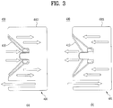
- FIG. 3 is a schematic cross-sectional view illustrating a driver unit 401 of an ear unit 300 according to the present invention.
- the degree of output of sound within a specific range may act as a variable helping determine the amount of ventilation of a receiver.
- the output of sound within a specific range may be adjusted by varying the amount of air introduced into or discharged from the housing 4001.
- Sound is generated via the vibration process in which the vibrating plate 410 repeats compression and expansion as illustrated in FIGS. 3(a) and 3(b) .
- the output in a specific frequency band may increase as the vibration displacement of the vibrating plate 410 increases, and the output in a specific frequency band may decrease as the vibration displacement of the vibrating plate 410 decreases.
- the vibration displacement of the vibrating plate 410 may be adjusted according to the amount of air that is introduced into or discharged from the driver unit 401.
- a relatively low pressure may be applied to the driver unit 401, and thus the vibration displacement of the vibrating plate 410 may be increased, which may increase the output of sound within a specific range.
- a relatively high pressure may be applied to the driver unit 401, and thus the vibration displacement of the vibrating plate 410 may not be increased, which may decrease the output of sound within a specific range.
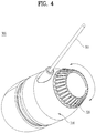
- FIG. 4 is a perspective view of the ear unit 300 according to the present invention.
- a function of adjusting relative tone by adjusting the output of sound at a specific frequency or within a specific frequency band is referred to as "equalizing".
- treble boost may be realized when the output in a low frequency band is reduced to thus increase the relative output in a high frequency band
- bass boost may be realized by increasing the output in a low frequency band to thus increase resonance thereof.
- the equalizing function may be of a software type, in which a signal of a sound source to be output is processed or modulated, or of a hardware type, in which tone is adjusted by changing the physical properties of hardware.
- the present invention proposes a hardware-type equalizing method.
- the ear unit 300 includes an ear housing 310 and a rotator 320.
- the rotator 320 may be coupled to the ear housing 310 so as to be rotated relative to the ear housing 310.
- the user may realize first equalizing by rotating the rotator 320 in a given direction, or may realize second equalizing by rotating the rotator 320 in an opposite direction.
- the first equalizing may correspond to a bass boost function
- the second equalizing may correspond to a treble boost function
- the rotation angle of the rotator 320 may be continuously changed over 360 degrees, but may be limited in some cases. That is, the rotator 320 may be rotated within a first angular range. When the rotator 320 is rotated to one end of the first angular range, the first equalizing may be performed. When the rotator 320 is rotated to the other end of the first angular range, the second equalizing may be performed.
- the user may reliably recognize whether the first equalizing is performed or the second equalizing is performed.
- the rotator 320 may need to be formed so as to ensure easy rotating operation.
- the rotator 320 may take the form of a disc covering the entire rear surface of the ear housing 310. Since the rotator 320 covers the entire rear surface of the ear housing 310, the user may easily rotate the rotator 320 by gripping the ear housing 310 with one hand and gripping the rotator 320 with the other hand.
- the rotator 320 may be provided on the outer circumferential surface thereof with a pattern for increasing frictional force. When frictional force is high, slippage of the hand upon rotation of the rotator 320 may be prevented.
- FIG. 5 is a partial exploded perspective view of the ear unit 300 according to the present invention.
- the ear housing 310 may have a bass hole 331 and a flat hole 332.
- the bass hole 331 and the flat hole 332 may be provided in a first surface of the ear housing 310, and the first surface may be the rear surface of the ear housing 310.
- equalizing may be performed based on the rotation of the rotator 320, which is coupled to the rear surface.
- the rotator 320 has an opening/closing hole 326.
- the opening/closing hole 326 may open or close the bass hole 331 or the flat hole 332 according to the rotation of the rotator 320, thereby performing different equalizing functions.
- bass boost equalizing may be performed.
- treble boost equalizing may be performed.
- Treble boost and bass boost merely refer to some embodiments of equalizing modes, and equalizing characteristics may be changed according to the shape and size of the aforementioned holes.
- the opening/closing hole 326 may be provided in a second surface of the rotator 320.
- the second surface means the surface that is opposite the first surface of the ear housing 310.
- the second surface may be realized by an inner bracket 321 of the rotator 320.
- the inner bracket 321 may serve not only to enable direct attachment to the ear housing 310, but also to guide rotation of the rotator 320. A detailed description will follow.
- the bass hole 331 and the flat hole 332 have different amounts of ventilation with respect to an enclosure of the ear housing 310.
- the bass hole 331 has an area larger than the flat hole 332 and thus provides a larger amount of ventilation than the flat hole 332.
- the flat hole 332 has an area smaller than the bass hole 331 and provides a smaller amount of ventilation than the bass hole 331 due to a duct structure thereof, which will be described later.
- FIG. 6 is a partial exploded perspective view of the ear unit 300 according to the present invention
- FIG. 7 is a front view illustrating the outer side of an inner case 311 and the inner side of an outer case 312.
- FIGS. 6 and 7 are described together.
- the ear housing 310 may be divided into the inner case 311, which directly defines an electric part 3101 in which elements such as a driver unit 401 is mounted, and the outer case 312, which surrounds and is coupled to an outer surface 3111 of the inner case 311.
- An inner surface 3121 of the outer case 312 may be coupled to the outer surface 3111 of the inner case 311.
- the amount of ventilation may be reduced via the flat hole 332, which is provided in the outer case 312, more particularly, in a hole plate 3122, and an inner hole 333, which is provided in the inner case 311, more particularly, in a damper layer 3112.
- the inner hole 333 is in an inner portion of the ear housing 310 beneath the first surface.
- the hole plate 3122 forms inner surface of the outer case 312, and the damper layer 3112 forms outer surface of the inner case 311. So the hole plate 3122 and the damper layer 3112 face with each other.
- the flat hole 332 and the inner hole 333 are not provided at the same location in the state in which the outer case 312 is coupled to the inner case 311. That is, the flat hole 332 and the inner hole 333 communicate with each other through a duct groove 334 formed in the inner surface 3121 of the outer case 312.
- the inner surface 3121 of the outer case 312 is sealed by the outer surface 3111 of the inner case 311 with respect to an area thereof excluding the duct groove 334.
- air inside the electric part 3101 in which the driver unit 401 is provided i.e. inside the enclosure, may be discharged outward from the ear housing 310 by passing through the inner hole 333, the duct groove 334, and the flat hole 332 in sequence, or may be introduced along the opposite path.
- the duct groove 334 defines a recessed area in the inner surface 3121 of the outer case 312.
- the duct groove 334 may have a C-shaped form in order to connect the inner hole 333 and the flat hole 332 to each other.
- the duct groove 334 may have any other shape depending on the required duct length.
- the bass hole 331 in the inner case 311 and the bass hole 331 in the outer case 312 may be disposed at the same location in the state in which the inner case 311 and the outer case 312 are coupled to each other. That is, the bass hole 331 in the inner case 311 and the bass hole 331 in the outer case 312 do not form different paths.
- the air inside the electric part 3101 may be directly introduced into or discharged from the respective bass holes 331 in the inner case 311 and the outer case 312.
- the amount of air introduced into or discharged from the enclosure i.e. the amount of ventilation, may be increased compared to the case in which the air passes through a path including the flat hole 332.
- a sealing gasket 341 is provided between the first surface of the ear housing 310 and the second surface of the rotator 320.
- the sealing gasket 341 prevents the generation of unexpected noise caused when air leaks from an unopened area when the opening/closing hole 326 opens the flat hole 332 or the bass hole 331.
- the sealing gasket 341 may have holes, which have the same shape as that of the flat hole 332 and the bass hole 331 and are formed in positions respectively corresponding to the flat hole 332 and the bass hole 331, and may be coupled to the outer side of the first surface of the ear housing 310.
- a fixing protrusion 342 may be provided on the outer side of the first surface of the ear housing 310, and a fixing recess 343, which corresponds to the shape of the fixing protrusion 342, may be provided in the sealing gasket 341.
- the inner bracket 321 of the rotator 320 is coupled to a rotating dial 346 and rotated along with the same.
- the opening/closing hole 326 formed in the inner bracket 321 may open or close at least one of the bass hole 331 or the flat hole 332 so that the air inside the enclosure is introduced into or discharged from only one of the two holes 331 and 332.
- a first ventilation mesh 344 may be coupled to the opening/closing hole 326 as needed, and may serve to further reduce the amount of ventilation.
- the rotating dial 346 may be coupled to the rear surface of the inner bracket 321.
- the rotating dial 346 may be formed with a pattern on the outer circumferential surface thereof to allow the user to easily grip and rotate the same, in the same manner as the above description.
- the rotating dial 346 may have at least one hole 3441, which adjusts the amount of ventilation, and a second ventilation mesh 348, which covers the hole 3441.
- FIG. 8 provides a rear perspective view of the rotator 320 and a front perspective view of the ear housing 310 and FIG. 9 is a longitudinal cross-sectional view of the ear unit 300.
- FIGS. 8 and 9 are described together.
- the rotator 320 is rotatably coupled to the ear housing 310.
- the ear housing 310 may include a coupling flange 313, which defines a circular opening.
- a rotating hook portion 322 of the rotator 320 is fastened, i.e. coupled, to the coupling flange 313 using a hook 3222 so as to be rotated along the inner circumferential surface of the coupling flange 313.
- An outer circumferential surface 3221 of the rotating hook portion 322 and the inner circumferential surface of the coupling flange 313 may be engaged with each other to guide the rotation of the rotator 320.
- the hook 3222 of the rotating hook portion 322 may be disposed inside the coupling flange 313 and may be located in the inner space defined by the coupling flange 313.
- the rotation angle of the rotator 320 may be realized by a guide portion 327, which includes a stepped guide portion 323 of the rotator 320 and the fixing protrusion 342 provided on the first surface of the ear housing 310.
- the guide portion 327 is provided between the ear housing 310 and the rotator 320 to limit a rotation angle of the rotator 320 between a first position at a first end of the rotation angle and a second position at a second end of the rotation angle.
- Opposite boundaries of the stepped guide portion 323 may be caught by the fixing protrusion 342 as the rotator 320 is rotated to one end or the other end of the first angular range, so as to enable the rotation of the rotator 320 within the first angular range.
- the rotating hook portion 322 may include a plurality of hook protrusions 322a.
- the plurality of hook protrusion 322a extend from the second surface towards the first surface. And the plurality of hook protrusion 322a may be spaced about the inner circumferential surface of the circular opening.
- the hook protrusions 322a may be separated from each other and thus, may have elasticity for hook coupling.
- the hook protrusions 322a may be gathered to pass through an opening in the coupling flange 313, and may then be returned and fixed by elastic restoration after the rotator 320 is coupled to the ear housing 310.
- the rotating hook portion 322 may fail to completely restore the original state thereof due to a manufacturing tolerance or physical deformation depending on the material thereof, whereby the rotator 320 may not be completely fastened to the ear housing 310.
- This problem may not only simply cause an unwanted gap or movement, but may also have an effect on the amount of ventilation, thereby having an unintended effect on the output of sound.
- a rubber support element 324 may be used to outwardly open the hook protrusions 322a so as to prevent the hook protrusions 322a from being not opened to the original position thereof, or from being insufficiently opened, after being compressed, due to the material physical properties thereof.
- the plurality of hook protrusions press the hook protrusions towards the inner circumferential surface of the circular opening.
- the rubber support element 324 may be formed of an elastic material.
- the rubber support element 324 may consequently have the effect of further increasing the force required for the rotation of the rotator 320, thereby allowing the rotator 320 to be rotated only when the user applies sufficient force thereto.
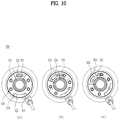
- FIG. 10 is a rear view of the ear unit 300 illustrating several states having a difference as to the degree of rotation of the rotator 320.
- the rotator 320 may be rotated relative to the ear housing 310 within the first angular range.
- the first angular range is determined by the widths of the fixing protrusion 342 and the stepped guide portion 323.
- FIG. 10(a) illustrates a first state in which the rotator 320 rotates to one end within the first angular range
- FIG. 10(c) illustrates a second state in which the rotator 320 rotates to the other end within the first angular range
- FIG. 10(b) illustrates a third state between the states of FIGS. 10(a) and 10(b) .
- the opening/closing hole 326 is located in the first position and opens the bass hole 331 and closes the flat hole 332. It may mean that the rotator 320 is rotated to the first end of the rotation angle.
- the electric part 3101 of the ear housing 310 which defines a resonance space, allows the introduction or discharge of air only through the bass hole 331.
- the shape and size of the opening/closing hole 326 may be equal to or greater than those of the bass hole 331. When the size of the opening/closing hole 326 is equal to or greater than the size of the bass hole 331, the opening/closing hole 326 may prevent the generation of noise in the intended introduction or discharge of air through the bass hole 331.
- the opening/closing hole 326 is located in the second portion and opens the flat hole 332 and closes the bass hole 331. It may mean that the rotator 320 is rotated to the second end of the rotation angle.
- the electric part 3101 of the ear housing 310 which defines a resonance space, allows the introduction or discharge of air only through the flat hole 332. The path along which air is introduced into or discharged from the flat hole 332 has been described above, and thus a repeated description thereof will be omitted.
- the shape and size of the opening/closing hole 326 may be equal to or greater than those of the flat hole 332.
- the reason thereof is the same as the above-described reason why the shape and size of the opening/closing hole 326 is equal to or greater than those of the bass hole 331.
- the opening/closing hole 326 is located in the third position between the first position and the second position and may open portions of both the bass hole 331 and the flat hole 332simultaneously. Specifically, there may not occur the case in which the opening/closing hole 326 completely closes both the entire bass hole 331 and the entire flat hole 332 when the rotator 320 is rotated from the first state to the second state.
- the ear unit wire 301 electrically connects the ear unit 300 and the main body 200 to each other.
- the ear unit wire 301 is connected to an electronic element of the electric part 3101 of the ear housing 310.
- the ear unit wire 301 discharged from the ear housing 310 is surrounded at a predetermined distance by a wire support element 302 in order to prevent damage thereto.
- a discharged portion of the ear unit wire 301 and the wire support element 302 are provided on the side surface of the ear housing 310. This is because they need to be designed so as to avoid the rotator 320 in consideration of rotation of the rotator 320.
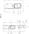
- FIG. 11 is a view illustrating one area of the portable sound device 100.
- the ear unit 300 is selectively seated in the main body 200, more particularly, in the neck-band housing 210.
- the neck-band housing 210 have a first end configured to allow the ear unit wire 301.
- the ear unit wire 301 of the ear unit 300 is introduced into or discharged from the neck-band housing 210.
- the neck-band housing 210 includes a seating portion 220 for seating the ear unit 300 therein.
- the seating portion 220 includes a seating surface 221, which is in contact with the ear unit 300 seated thereon.
- the seating surface 221 may be in contact with the rear surface of the ear unit 300, i.e. the rear surface of the rotator 320.
- the seating portion 220 has therein a through-hole 222, through which the ear unit wire 301 of the ear unit 300 is introduced into or discharged from the electric part of the neck-band housing 210.
- the through-hole 222 allows the ear unit wire 301 to extend through the seating portion 220.
- the ear unit 300 since the unit wire 301 is provided on the rear of the ear unit 300, the ear unit 300 has not been formed to have a large width. Thus, the ear unit 300 is typically seated such that the longitudinal direction thereof is parallel to the longitudinal direction of the neck-band housing 210 (hereinafter, referred to as a first direction).
- the ear unit 300 since the ear unit wire 301 is provided on the side surface of the ear unit 300, more particularly, the ear housing 310, the ear unit 300 has a larger width D1 than that in the related art.
- the ear unit 300 is seated such that the longitudinal direction thereof is parallel to the first direction, there is a risk of the width D3 of the neck-band housing 210 being excessively large.
- the angle between the direction in which the ear unit wire 310 is introduced into or discharged from the electric part of the neck-band housing 210 and the direction in which the ear unit wire 310 is discharged from the ear unit 300 may be large, which may deteriorate the durability of the ear unit wire 301.
- the ear unit 300 may be seated in the seating portion 220 such that the longitudinal direction of the ear unit 300 is tilted at a predetermined angle relative to the first direction of the neck-band housing 210.
- the seating surface 221 is formed so as to be tilted relative to the first direction of the neck-band housing 210.
- the neck-band housing 210 may have a small width D3.
- the ear unit wire 301 may be disposed so as to be parallel to or substantially parallel to the direction in which the ear unit wire 301 is discharged from the ear unit 300 and the direction in which the ear unit wire 301 is introduced into or discharged from the electric part of the neck-band housing 210, which may minimize deterioration in the durability of the ear unit wire 301.
- the seating surface 221 and the through-hole 222 may be spaced apart from each other. That is, the seating surface 221 may be provided in a first area of the seating portion 220 and the through-hole 222 may be provided in a second area of the seating portion 220 so that that the seating surface 221 and the through-hole 222 are spaced apart from each other.
- the width of the neck-band housing 210 may be determined so as to sufficiently contain the width D2 of the ear unit 300 in the tilted state of the ear unit 300.
- the seating portion 220 may be provided so as to surround, in particular, the entire upper portion of the ear unit 300.
- the ear unit 300 When the ear unit 300 is seated in the seating portion 220 of the neck-band housing 210, the ear unit 300 may be provided so as not to protrude when viewed from the upper surface of the portable sound device 100. This minimizes external shocks from being directly transmitted to the seated ear unit 300.
- the seating portion 220 may surround a portion of the side surface of the ear unit 300 so as to protect the ear unit 300. However, the outer side surface of the seating portion 220 may be opened more than the inner side surface so as not to prevent attachment/detachment of the ear unit 300 to or from the seating portion 220.
- the seating portion 220 may be formed so as to be opened without surrounding the lower portion of the ear unit 300, so as not to prevent attachment/detachment of the ear unit 300.
- FIG. 12 is a partial exploded rear perspective view of the portable sound device 100.
- FIG. 13 is a cross-sectional view taken along line A-A' of FIG. 2 . For convenience of description, FIGS. 12 and 13 are described together.
- the neck-band housing 210 which defines the electric part, may be formed via the coupling of an upper housing 2101 and a lower housing 2102.
- the seating portion 220 may be inserted into and coupled into the open area 2103 in the end of the neck-band housing 210.
- the structure of separately coupling the seating bracket 2201 to the neck-hand housing 210 serves to prevent shocks applied to the seating portion 220 from being directly transmitted to the neck-band housing 210.
- the structure of separately coupling the seating bracket 2201 to the neck-hand housing 210 serves to prevent shocks applied to the seating portion 220 from being directly transmitted to the neck-band housing 210.
- through sectionalization of the main body 200 it is possible to enable independent replacement of respective areas.
- a support portion 223 may support the upper surface, the lower surface, and one side surface of the neck-band housing 210 inside the open area 2103, thereby securing a sufficient support area through this three-sided supporting. This may prevent the seating bracket 2201 from moving relative to the neck-band housing 210 due to the generation of a gap therebetween.
- the seating bracket 2201 may be further firmly fixed to the neck-band housing 210 through a support hole 224.
- a coupling boss 2104 may penetrate the support hole 224 so as to couple the upper portion and the lower portion of the neck-band housing 210.
- the seating bracket 2201 may include an opening 2331 in the lower surface thereof so as not to interfere with a protrusion 2105, which is provided on the neck band housing 210.
- the size of the opening 2331 may correspond to the size of the protrusion 2105 so as to allow the support portion 223 to support the protrusion 2105.
- the seating surface 221 and the through-hole 222 described above may be provided in the seating bracket 2201.
- An upper-end cover 2202 may be coupled to the outer upper end of the seating bracket 2201 so as to define the exterior appearance of the upper end of the seating portion 220.
- a decorative ring 225 may be fitted and coupled between the neck-band housing 210 and the seating bracket 2201.
- a first magnetic element 251 may be provided inside the seating surface 221 in order to guide seating of the ear unit 300.
- a second magnetic element 325 may be mounted in the ear unit 300 so as to generate magnetic attraction with the first magnetic element 251.
- the second magnetic element 325 may be provided in the rotation axis center of the rotator 320. This serves to prevent a change in the relative positions of the second magnetic element 325 and the first magnetic element 251 despite rotation of the rotator 320.
- FIG. 14 is a rear exploded perspective view of the portable sound device 100.
- a conducting wire 231 electrically interconnects electronic elements of both the neck-band housings 210.
- the conducting wire 231 is fixed by a wire bracket 232 so as to keep the shape thereof.
- a wire case 233 surrounds the wire bracket 232 and defines a portion of the exterior appearance of the portable sound device 100.
- the wire case 233 may include an inner wire case 2331, which faces the inner side of a curved portion of the portable sound device 100, and an outer wire case 2332, which faces the outer side of the curved portion.
- the inner wire case 2331 and the outer wire case 2332 may be coupled and fixed to each other.
- the wire bracket 232 may include a bellows-shaped portion 241 to be fixed to each neck-band housing 210, and the inner wire case 2331 surrounds the wire bracket 232 so that the bellows-shaped portion 241 is exposed.
- An elastic wire portion 234 refers to an area that interconnects both the neck-band housings 210 or both the wire cases 233.
- the elastic wire portion 234 may have elasticity and thus be bendable.
- the elastic wire portion 234 includes an elastic wire 2341 and an elastic wire tube 2342.
- the elastic wire 2341 may have a property by which, even if it is deformed by a predetermined force, it returns to its original shape when the force is removed.
- the elastic wire 2341 may be formed of a shape memory alloy.
- the elastic wire tube 2342 defines a portion of the exterior appearance of the portable sound device 100 and forms a hollow region in which the elastic wire 2341 and the conducting wire 231 may be mounted.
- the elastic wire tube 2342 may be formed of an elastic material and may be deformed and then returned along with the elastic wire 2341.
- the elastic wire portion 234 may correspond to the back of the neck when the portable sound device 100 is worn around the user's neck.
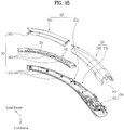
- FIG. 15 is a partial rear perspective view of the portable sound device 100.
- the inner wire case 2331 and the outer wire case 2332 may be stacked one above another in a second direction, and may be coupled to each other.
- the second direction may refer to the direction from the inner side to the outer side of the curved portion of the portable sound device 100.
- the inner wire case 2331 may have a curved surface, the inclination of which gradually varies from the plane orthogonal to the second direction to the plane orthogonal to a third direction.
- the area having this curved surface may be in natural contact with the user's neck and may maximally prevent the boundary between the inner wire case 2331 and the outer wire case 2332 from coming into contact with the user's neck, causing discomfort.
- the third direction may refer to the direction from the lower surface toward the upper surface of the portable sound device 100.
- the upper housing 2101 and the lower housing 2102 of the neck-band housing 210 which define the electric part, may be stacked in the third direction.
- the upper housing 2101, the lower housing 2102, and a main board are stacked in the third direction, stable arrangement of electronic elements may be achieved, and the assembly process may be convenient.
- a first screw is used to fix the inner wire case 2331, the wire bracket 232, and the outer wire case 2332.
- a first screw hole 242 forms relative surfaces to which the first screw is fixed.
- a second screw is used to fix the lower housing 2102 and the upper housing 2101 of the neck-band housing 210.
- a second screw hole 243 forms relative surfaces to which the second screw is fixed.
- the first screw hole 242 may be formed in the second direction in consideration of the direction in which the inner wire case 2331 and the outer wire case 2332 are stacked.
- the second screw hole 243 may be formed in the third direction in consideration of the direction in which the lower housing 2102 and the upper housing 2101 of the neck-band housing 210 are stacked.
- the first screw hole 242 in the inner wire case 2331 and the second screw hole 243 in the lower housing 2102 of the neck-band housing 210 may be formed respectively to penetrate the inner wire case 2331 and the lower housing 2102.
- the inner wire case 2331 and the lower housing 2102 of the neck-band housing 210 may be manufactured separately. That is, the inner wire case 2331 and the lower housing 2102 of the neck-band housing 210 may be injection-molded using molds, and the orientations of the molds need to be different because of the screw holes. Therefore, the inner wire case 2331 and the lower housing 2102 of the neck-band housing 210 may be manufactured separately.
- the outer wire case 2332 and the upper housing 2101 are not configured so that the first and second screw holes penetrate the same, the orientations of the screw holes are independent of the orientations of the molds.
- the outer wire case 2332 and the upper housing 2101 may be integrally manufactured.
- a plurality of first screws may be provided so as to further firmly fasten the wire bracket 232 and the outer wire case 2332 to each other.
- first screw among the plurality of first screws may be fastened to the inner wire case 2331. This is because the inner wire case 2331 is configured so as to be in contact with the user's neck as described above, and therefore it is necessary to minimize the area in which the screw is exposed.
- the wire bracket 232 may have therein a wire seating groove 235 in which the conducting wire 231 is seated, in order to minimize movement of the conducting wire 231.
- the wire seating groove 235 may form a curved area configured to avoid the first screw hole 242.
- the wire seating groove 235 having the bent area may maximize the area of a seated surface of the conducting wire 231 when the conducting wire 231 is seated so as to further firmly fix the conducting wire 231, which may prevent short-circuiting of the conducting wire 231 due to tension in the longitudinal direction.
- the seating groove 235 includes a plurality of bent portions to deviate to one side of each of the plurality of the first screw holes 242 in the corresponding wire cases 233.
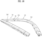
- FIG. 16 is a view illustrating one area of the portable sound device 100 which is viewed from the inner side toward the outer side.
- the outer surface of the elastic wire portion 234, more particularly, the elastic wire tube 2342 forms a continuous surface along with the outer surface of the wire case 233. This serves to prevent uncomfortable wearing sensation when it is seated on the user's neck.
- a boundary 261 between the elastic wire portion 234 and the inner wire case 2331 is an area having a high probability of being in contact with the user's neck, and thus may form a continuous surface with increased accuracy.
- the boundary 261 between the elastic wire portion 234 and the wire case 233 may have a curved line in an arbitrary direction.
- the arbitrary direction refers to any of all directions that are arbitrarily designated, and the boundary 261 may be configured so as not to have a straight line when viewed from any direction.
- a boundary having a curved shape may prevent the user's hair from becoming stuck in a boundary gap.
- the boundary between the elastic wire portion 234 and the wire case 233 may have an S-shaped form.
- the boundary having an S-shaped form may minimize a straight line area and thus may further reduce the probability of hair being stuck in the gap.
Landscapes
- Engineering & Computer Science (AREA)
- Physics & Mathematics (AREA)
- Acoustics & Sound (AREA)
- Signal Processing (AREA)
- Health & Medical Sciences (AREA)
- Otolaryngology (AREA)
- Manufacturing & Machinery (AREA)
- Headphones And Earphones (AREA)
- Telephone Set Structure (AREA)
Description
- The present invention relates to an ear unit, which outputs a sound signal, and a portable sound device including such an ear unit, which transmits and receives a sound signal to and from a terminal via wired or wireless communication and transmits a control signal to control the terminal in response to a signal input via a user input unit.
- A sound device refers to a device that receives a sound signal from a terminal and transmits sound information, collected via a microphone, to the terminal. Although a wired-type portable sound device in which a jack thereof is fitted to an earphone port of a terminal to receive a sound signal has conventionally been used, demand for wireless-communication-type portable sound devices has recently increased in terms of mobility and use convenience.
- Portable sound devices designed in consideration of portability have been developed to allow a user to carry the device on the body, such as a headphone-type device fitted around the head in a band shape or an earphone-type device hanging on or inserted into the ear.
- In particular, recently, use of a portable sound device having a neck-band shape that the user can hang around the neck has increased.
- Such a portable sound device having a neck-band shape includes an ear unit, which is directly worn on the user's ear. The ear unit may be seated and stored in a neck-band housing of the portable sound device having a neck-band shape when it is not in use.
- For this reason, the ear unit may need to have a small size and a light weight.
- In addition, since users have become more interested in sound quality, there is demand for adjusting or improving the sound quality of the ear unit.
- As an example, European Patent Application Publication No.
2 822 293 A2 discloses an earphone provided with a body, a front cavity, a rear cavity and a decorating plate. The body includes a connecting disk, an earbud member and a signal cable. A recessed groove is formed at two sides of the connecting disk, and a small air hole and a large air hole are formed so as to pass through the inner surface of the recessed groove. The connecting disk communicates with the front cavity and the rear cavity through the small air hole and the large air hole. - Accordingly, the present invention is directed to an ear unit and a portable sound device that substantially obviate one or more in problems due to limitations and disadvantages of the related art.
- An object of the present invention devised to solve the problem lies on a portable sound device having enhanced usability such as improved sound quality.
- Additional advantages, objects, and features will be set forth in part in the description which follows and in part will become apparent to those having ordinary skill in the art upon examination of the following or may be learned from practice. The objectives and other advantages may be realized and attained by the structure particularly pointed out in the written description and claims hereof as well as the appended drawings.
- To achieve these objects and other advantages and in accordance with the purpose of the invention, as embodied and broadly described herein, in accordance with an aspect of the present invention, there is provided an ear unit including the features of claim 1. An ear unit according to claim 1 includes an ear housing including a bass hole and a flat hole formed in a rear surface of the ear housing, the bass hole being larger than the flat hole; a driver unit mounted in the ear housing; and a rotator rotatably coupled to the ear housing, the rotator including an inner bracket opposite the rear surface of the ear housing, the inner bracket having an opening/closing hole configured to open or close the bass hole or the flat hole according to a rotational position of the rotator, characterized in that the ear housing further includes: an inner case having a damper layer and an inner hole formed at the damper layer; an outer case coupled to outer surface of the inner case, the outer case having a hole plate, and the bass hole and the flat hole formed at the hole plate; and a duct groove formed on the inner surface of the hole plate so as to connect the inner hole and the flat hole.
- In addition, the ear unit may further include a sealing gasket provided between the rear surface of the ear housing and the inner bracket of the rotator and including connection holes respectively corresponding to the bass hole and the flat hole.
- In addition, the ear housing may further include a coupling flange configured to define a circular opening, and the rotator may further include a rotating hook portion fastened to the coupling flange so as to rotate along an inner circumferential surface of the coupling flange inside the opening.
- In addition, the rotating hook portion may include a plurality of hook protrusions provided along the inner circumferential surface of the coupling flange inside the opening, and a rubber support element fitted between the hook protrusions to open the hook protrusions.
- In addition, the ear unit may further include a guide portion provided between the ear housing and the rotator to limit a rotation angle of the rotator, the opening/closing hole may open an overall area of the bass hole in a first state in which the rotator is rotated to one end of the rotation angle, and the opening/closing hole may open an overall area of the flat hole in a second state in which the rotator is rotated to a remaining end of the rotation angle.
- In addition, the rotator may be rotated to a third state in which the opening/closing hole opens a partial area of the bass hole and a partial area of the flat hole at the same time.
- According to a comparative example, a portable sound device may include an ear unit including an ear housing, in which a driver unit is mounted, and a rotator coupled to a rear surface of the ear housing and configured to rotate, an ear unit wire including one end coupled to a side surface of the ear housing, a neck-band housing configured to form an electric part in a first direction and to allow the ear unit wire to be introduced thereinto or discharged therefrom, and a seating portion including a seating surface formed so as to be tilted relative to the first direction by a particular angle and a through-hole configured to allow the ear unit wire to penetrate, the seating portion being coupled to an end of the neck-band housing, wherein the ear unit includes a rear surface configured to be seated on the seating portion, and the seating portion surrounds an entire upper portion of the ear unit.
- In the comparative example, the seating surface may be formed on a first area of the seating portion, the through-hole may be formed in a second area of the seating portion, and the first area and the second area may be spaced apart from each other.
- In the comparative example, the end of the neck-band housing may form an open area, and the seating portion may further include a seating bracket inserted into and coupled to the open area in the neck-band housing.
- In the comparative example, the seating bracket may include a support portion configured to support an upper surface, a lower surface, and one side surface of the neck-band housing inside the open area, and a support hole formed in an area of the support portion so that a coupling boss penetrates therethrough to couple an upper portion and a lower portion of the neck-band housing to each other.
- In the comparative example, the portable sound device may further include a conducting wire configured to electrically interconnect opposite neck-band housings, a wire bracket configured to support the conducting wire and fastened at one side thereof to each neck-band housing, a wire case configured to surround the wire bracket so as to form an external appearance, and a first screw hole configured to enable fastening between the wire case and the wire bracket, wherein the first screw hole is provided in each of three positions including one end, a middle end, and a remaining end of the wire bracket.
- In the comparative example, the portable sound device may further include a wire seating groove formed in the wire bracket so that the conducting wire is seated therein, and the seating groove may include an area corresponding to the first screw hole and having a bent shape so as to deviate to one side.
- In the comparative example, the wire case may include an inner wire case configured to surround one surface of the wire bracket, an outer wire case coupled to the inner wire case and configured to surround a remaining surface of the wire bracket, and the first screw hole formed in the inner wire case in a second direction, the neck-band housing may include an upper neck-band housing, a lower neck-band housing coupled to the upper neck-band housing, and a second screw hole formed in the lower neck-band housing in a third direction, the second direction and the third direction may be different directions, the outer wire case and the upper neck-band housing may be integrally manufactured, and the inner wire case and the lower neck-band housing may be manufactured separately.
- In the comparative example, the portable sound device may further include an elastic wire portion including opposite ends each connected to the wire bracket, the elastic wire portion being configured to form a continuous surface along with the wire case so as to define an external appearance, and a boundary between the elastic wire portion and the wire case may include a curved area in an arbitrary direction.
- In the comparative example, the boundary between the elastic wire portion and the wire case may have an S-shaped form.
- In the comparative example, the portable sound device may further include a first magnetic element provided inside the seating surface, and a second magnetic element configured to
generate magnetic attraction with the first magnetic element and provided on a rotation center axis of the rotator. - It is to be understood that both the foregoing general description and the following detailed description of the present invention are exemplary and explanatory and are intended to provide further explanation of the present invention as claimed.
- The accompanying drawings, which are included to provide a further understanding of the present invention and are incorporated in and constitute a part of this application, illustrate embodiment(s) of the present invention and together with the description serve to explain the principle of the present invention. In the drawings:
-
FIG. 1 is a block diagram for explaining a portable sound device according to an example not being part of the present invention; -
FIG. 2 is a front perspective view of the portable sound device according to an example not being part of the present invention; -
FIG. 3 is a schematic cross-sectional view illustrating a driver unit of an ear unit according to the present invention; -
FIG. 4 is a perspective view of the ear unit according to the present invention; -
FIG. 5 is a partial exploded perspective view of the ear unit according to the present invention; -
FIG. 6 is a partial exploded perspective view of the ear unit according to the present invention; -
FIG. 7 is a front view illustrating the outer side of an inner case and the inner side of an outer case; -
FIG. 8 provides a rear perspective view of a rotator and a front perspective view of an ear housing; -
FIG. 9 is a longitudinal cross-sectional view of the ear unit; -
FIG. 10 is a rear view of the ear unit illustrating several states having a difference as to the degree of rotation of the rotator; -
FIG. 11 is a view illustrating one area of the portable sound device according to an example not being part of the present invention; -
FIG. 12 is a partial exploded rear perspective view of the portable sound device according to an example not being part of the present invention; -
FIG. 13 is a cross-sectional view taken along line A-A' ofFIG. 2 ; -
FIG. 14 is a rear exploded perspective view of the portable sound device according to an example not being part of the present invention; -
FIG. 15 is a partial rear perspective view of the portable sound device according to an example not being part of the present invention; and -
FIG. 16 is a view illustrating one area of the portable sound device according to an example not being part of the present invention, which is viewed from the inner side toward the outer side. - Hereinafter, embodiments disclosed in this specification will be described in detail with reference to the accompanying drawings. In the drawings, the same or similar elements are denoted by the same reference numerals even though they are depicted in different drawings, and a repeated description thereof is omitted. With respect to constituent elements used in the following description, suffixes "module" and "unit" are given or mingled with each other only in consideration of ease in the preparation of the specification, and do not have or serve as different meanings. In the following description of the present invention, a detailed description of known functions and configurations incorporated herein will be omitted when it may make the subject matter of the embodiments disclosed in this specification rather unclear. In addition, it is to be understood that the accompanying drawings are intended to assist easy understanding of the embodiments disclosed in this specification and are not intended to limit the scope of this specification.
- A sound device refers to a device that receives a sound signal from a terminal and transmits sound information, collected via a microphone, to the terminal. Although a wired-type portable sound device in which a jack thereof is fitted to an earphone port of a terminal to receive a sound signal has conventionally been used, demand for wireless-communication-type portable sound devices has recently increased in terms of mobility and use convenience.
- Portable sound devices designed in consideration of portability have been developed to allow a user to carry the device on the body, such as a headphone-type device fitted around the head in a band shape or an earphone-type device hanging on or inserted into the ear.
- In particular, recently, use of a portable sound device having a neck-band shape that the user can hang around the neck has increased.
- Such a portable sound device having a neck-band shape includes an ear unit, which is directly worn on the user's ear. The ear unit may be seated and stored in a neck-band housing of the portable sound device having a neck-band shape when it is not in use.
- For this reason, the ear unit may need to have a small size and a light weight.
- In addition, since users have become more interested in sound quality, there is demand for adjusting or improving the sound quality of the ear unit.
-
FIG. 1 is a block diagram for explaining aportable sound device 100. - The
portable sound device 100 may include, for example, awireless communication unit 110, aninput unit 120, asensing unit 130, anoutput unit 140, aninterface unit 150, acontroller 160, and apower supply unit 170. - The constituent elements illustrated in
FIG. 1 may not be necessary to realize theportable sound device 100, and thus theportable sound device 100 described in this specification may have a greater or smaller number of constituent elements than the constituent elements enumerated above. - More specifically, among the aforementioned constituent elements, the
wireless communication unit 110 may include one or more modules, which enable wireless communication between theportable sound device 100 and a wireless communication system, between theportable sound device 100 and another mobile terminal, or between theportable sound device 100 and an external server. In addition, thewireless communication unit 110 may include one or more modules, which connect theportable sound device 100 to one or more networks. - The
wireless communication unit 110 may include at least one of a short-range communication module 111 or alocation information module 112. Alternatively, thewireless communication unit 110 may include, for example, a mobile communication module or a wireless Internet module as needed. - The short-
range communication module 111 is used for short-range communication, and may support short-range communication using at least one of BLUETOOTH™, Radio Frequency Identification (RFID), Infrared Data Association (IrDA), Ultra-Wideband (UWB), ZigBee, Near Field Communication (NFC), Wireless Fidelity (Wi-Fi), Wi-Fi Direct, or Wireless Universal Serial Bus (Wireless USB). - The short-
range communication module 111 may support wireless communication between theportable sound device 100 and a wireless communication system, between theportable sound device 100 and another mobile terminal, or between theportable sound device 100 and a network in which another mobile terminal (or an external server) is located using a short-range wireless communication network. The short-range wireless communication network may be a short-range wireless personal area network. - The short-
range communication module 111 may sense (or recognize), for example, a terminal that can perform communication near theportable sound device 100. In addition, when a sensed terminal is a device that is authorized to communicate with theportable sound device 100, thecontroller 160 may receive at least some of the data processed in the mobile terminal via the short-range communication module 111. Thus, the user of theportable sound device 100 may use the data processed in the terminal via a wearable device. - For example, when a call is received by, for example, a terminal, the user may engage in a telephone conversation using the
portable sound device 100. - The
location information module 112 is a module for acquiring the location (or the current location) of theportable sound device 100, and a representative example thereof may be a global positioning system (GPS) module or a wireless fidelity (Wi-Fi) module. For example, when theportable sound device 100 uses the GPS module, the mobile terminal may acquire the location of theportable sound device 100 using a signal transmitted from a GPS satellite. In another example, when theportable sound device 100 uses a Wi-Fi module, the mobile terminal may acquire the location of theportable sound device 100 based on information from a wireless access point (AP), which transmits or receives a wireless signal to or from the Wi-Fi module. As needed, thelocation information module 112 may perform the function of any other modules of thewireless communication unit 110 so as to replace the corresponding module or to be additionally used along with the corresponding module, in order to obtain data regarding the location of theportable sound device 100. Thelocation information module 112 is a module used for acquiring the location (or the current location) of theportable sound device 100, and is not limited to a module that directly calculates or acquires the location of theportable sound device 100. - The
input unit 120 may include, for example, a microphone (MIC) 121 or an audio input unit for the input of an audio signal, and auser input unit 122 for receiving information from a user (e.g. a touch key or a push key). Voice data or image data collected by theinput unit 120 may be analyzed and may be processed in response to a user control command. - The
user input unit 122 is configured to allow the user to control theportable sound device 100. Examples of theuser input unit 122 may include a call button, a button for, for example, volume adjustment, a power button, and a storage button for storing a sound cable into a main body. - The
user input unit 122 may include only a call button and a pair of volume adjustment buttons, and may further include a play/stop button and a music order change button. - Since the size of the
portable sound device 100 is limited, and in many cases, the user performs input without viewing theuser input unit 122, provision of a large number of buttons may make it difficult to distinguish the functions of the buttons from each other. Thus, a limited number of buttons may be used in a manner such that the number of inputtable control commands may be increased by combining the time for which each of a plurality of buttons is pushed with the number of times the button is pushed. - The
microphone 121 converts an external sound signal into electrical voice data. The converted voice data may be utilized depending on the function that is being performed by the portable sound device 100 (or an application that is being executed), or may be transmitted to an external terminal or an external server via thewireless communication unit 110. Meanwhile, various noise removal algorithms may be realized in themicrophone 122 in order to remove noise generated in the process of receiving an external sound signal. - The
sensing unit 130 may include one or more sensors for sensing at least one of information on the interior of theportable sound device 100, information on the environment surrounding theportable sound device 100, or user information. For example, thesensing unit 130 may include at least one of aproximity sensor 131, anillumination sensor 132, a touch sensor, an acceleration sensor, a magnetic sensor, a G-sensor, a gyroscope sensor, a motion sensor, an RGB sensor, an infrared (IR) sensor, a finger scan sensor, an ultrasonic sensor, an optical sensor, a microphone (see reference numeral 121), a battery gauge, an environmental sensor (e.g., a barometer, a hygrometer, a thermometer, a radiation sensor, a thermal sensor, or a gas sensor), or a chemical sensor (e.g. an e-nose, a healthcare sensor, or a biometric sensor). Meanwhile, theportable sound device 100 disclosed in this specification may combine and utilize information sensed by at least two or more sensors among the aforementioned sensors. - In particular, a sensor, which senses whether or not an earphone to be described later is located on a holder, may be provided. As a representative example of such a sensor, a magnetic sensor may be used.
- The
output unit 140 serves to generate, for example, visual output, acoustic output, or haptic output. Theoutput unit 140 may include at least one of asound output unit 141, ahaptic module 142, or alight output unit 143. - The
sound output unit 142 is a device that outputs sound in response to a sound signal. A representative example of thesound output unit 142 may include an earphone, which transmits sound while being worn on the user's ear, and a speaker, which outputs sound in the state in which the user is not wearing the earphone. - The
interface unit 150 serves as a path to various types of external devices connected to theportable sound device 100. Theinterface unit 150 may include at least one of an external charger port, or a wired/wireless data port. When an external device is connected to theinterface unit 150, theportable sound device 100 may perform appropriate control related to the connected external device. - The
controller 160 typically controls the overall operation of theportable sound device 100, in addition to operations related to the application. Thecontroller 160 may process, for example, signals, data, and information input to or output from the constituent elements described above. - The
power supply unit 170 receives external power or internal power under the control of thecontroller 160 and supplies the power to the respective constituent elements included in theportable sound device 100. Thepower supply unit 170 may include a battery, and the battery may be a built-in battery or a replaceable battery. - At least some of the constituent elements described above may be operated in cooperation with each other in order to realize the operation of the
portable sound device 100 or a control method thereof, which will be described below. -
FIG. 2 is a front perspective view of theportable sound device 100. - The
portable sound device 100 basically includes neck-band housings 210, which are provided on opposite sides, awire unit 201, which interconnects both the neck-band housings 210, and anear unit 300. - The
wire unit 201 and the neck-band housings 210 may define amain body 200, and may be used in the state of being seated on the user's neck. Themain body 200 may have a U-shaped form having an opening in one side thereof, and may have an ergonomically curved shape. - Each neck-
band housing 210 defines an electric part in which major elements, such as a battery and a main board, are mounted. - The
ear unit 300 is equipped with a driver unit, which directly outputs sound. Theear unit 300 may be electrically connected to electronic elements of the neck-band housing 210 via anear unit wire 301. - The
ear unit wire 301 may be discharged from the neck-band housing 210 when theear unit 300 is in use, and may be introduced into the neck-band housing 210 when theear unit 300 is not in use. When in use, theear unit 300 may be separated from a seating portion of the neck-band housing 210 and may be worn on the user's ear. When not in use, a rear portion of theear unit 300 may be seated and stored in the seating portion of the neck-band housing 210. - The
ear unit 300 may output sound by changing the quality of sound depending on user selection. Hereinafter, this feature will be described. -
FIG. 3 is a schematic cross-sectional view illustrating adriver unit 401 of anear unit 300 according to the present invention. - With regard to physical characteristics of the
ear unit 400, the degree of output of sound within a specific range may act as a variable helping determine the amount of ventilation of a receiver. - That is, in a
housing 4001 of theear unit 400 in which thedriver unit 401 is mounted, the output of sound within a specific range may be adjusted by varying the amount of air introduced into or discharged from thehousing 4001. - When a vibrating
plate 410 of thedriver unit 401 is compressed as illustrated inFIG. 3(a) , the inside of thedriver unit 401 is compressed, causing air to be discharged outward. When the vibratingplate 410 of thedriver unit 401 expands as illustrated inFIG. 3(b) , the inside of thedriver unit 401 expands, causing outside air to be introduced. - Sound is generated via the vibration process in which the vibrating
plate 410 repeats compression and expansion as illustrated inFIGS. 3(a) and 3(b) . - The output in a specific frequency band may increase as the vibration displacement of the vibrating
plate 410 increases, and the output in a specific frequency band may decrease as the vibration displacement of the vibratingplate 410 decreases. - The vibration displacement of the vibrating
plate 410 may be adjusted according to the amount of air that is introduced into or discharged from thedriver unit 401. - In the state in which a large amount of air is introduced into or discharged from the
driver unit 401, i.e. in the state in which the amount of ventilation is high, a relatively low pressure may be applied to thedriver unit 401, and thus the vibration displacement of the vibratingplate 410 may be increased, which may increase the output of sound within a specific range. - Conversely, in the state in which a small amount of air is introduced into or discharged from the
driver unit 401, i.e. in the state in which the amount of ventilation is low, a relatively high pressure may be applied to thedriver unit 401, and thus the vibration displacement of the vibratingplate 410 may not be increased, which may decrease the output of sound within a specific range. -
FIG. 4 is a perspective view of theear unit 300 according to the present invention. - A function of adjusting relative tone by adjusting the output of sound at a specific frequency or within a specific frequency band is referred to as "equalizing". For example, treble boost may be realized when the output in a low frequency band is reduced to thus increase the relative output in a high frequency band, or bass boost may be realized by increasing the output in a low frequency band to thus increase resonance thereof.
- The equalizing function may be of a software type, in which a signal of a sound source to be output is processed or modulated, or of a hardware type, in which tone is adjusted by changing the physical properties of hardware.
- The present invention proposes a hardware-type equalizing method.
- The
ear unit 300 includes anear housing 310 and arotator 320. Therotator 320 may be coupled to theear housing 310 so as to be rotated relative to theear housing 310. - The user may realize first equalizing by rotating the
rotator 320 in a given direction, or may realize second equalizing by rotating therotator 320 in an opposite direction. - For example, the first equalizing may correspond to a bass boost function, and the second equalizing may correspond to a treble boost function.
- The rotation angle of the
rotator 320 may be continuously changed over 360 degrees, but may be limited in some cases. That is, therotator 320 may be rotated within a first angular range. When therotator 320 is rotated to one end of the first angular range, the first equalizing may be performed. When therotator 320 is rotated to the other end of the first angular range, the second equalizing may be performed. - When the
rotator 320 is rotated within the first angular range, the user may reliably recognize whether the first equalizing is performed or the second equalizing is performed. - The concrete structure for allowing the
rotator 320 to be rotated within the first angular range will be described later. - Since the size of the
ear unit 300 is not large, therotator 320 may need to be formed so as to ensure easy rotating operation. Therotator 320 may take the form of a disc covering the entire rear surface of theear housing 310. Since therotator 320 covers the entire rear surface of theear housing 310, the user may easily rotate therotator 320 by gripping theear housing 310 with one hand and gripping therotator 320 with the other hand. - In addition, the
rotator 320 may be provided on the outer circumferential surface thereof with a pattern for increasing frictional force. When frictional force is high, slippage of the hand upon rotation of therotator 320 may be prevented. -
FIG. 5 is a partial exploded perspective view of theear unit 300 according to the present invention. - The
ear housing 310 may have abass hole 331 and aflat hole 332. In particular, thebass hole 331 and theflat hole 332 may be provided in a first surface of theear housing 310, and the first surface may be the rear surface of theear housing 310. - Through the provision of these holes in the rear surface, equalizing may be performed based on the rotation of the
rotator 320, which is coupled to the rear surface. - The
rotator 320 has an opening/closing hole 326. The opening/closing hole 326 may open or close thebass hole 331 or theflat hole 332 according to the rotation of therotator 320, thereby performing different equalizing functions. When the opening/closing hole 326 opens thebass hole 331, bass boost equalizing may be performed. When the opening/closing hole 326 opens theflat hole 332, treble boost equalizing may be performed. - Treble boost and bass boost merely refer to some embodiments of equalizing modes, and equalizing characteristics may be changed according to the shape and size of the aforementioned holes.
- The opening/
closing hole 326 may be provided in a second surface of therotator 320. The second surface means the surface that is opposite the first surface of theear housing 310. The second surface may be realized by aninner bracket 321 of therotator 320. - The
inner bracket 321 may serve not only to enable direct attachment to theear housing 310, but also to guide rotation of therotator 320. A detailed description will follow. - The
bass hole 331 and theflat hole 332 have different amounts of ventilation with respect to an enclosure of theear housing 310. Thebass hole 331 has an area larger than theflat hole 332 and thus provides a larger amount of ventilation than theflat hole 332. Theflat hole 332 has an area smaller than thebass hole 331 and provides a smaller amount of ventilation than thebass hole 331 due to a duct structure thereof, which will be described later. - In general, the smaller the amount of ventilation, the more the bass boost characteristics may be reduced. This may be achieved by reducing the size of a hole, but an unlimited reduction in the diameter of a hole is impossible in terms of hole processing. Thus, a duct structure may be realized to adjust the amount of ventilation.
-
FIG. 6 is a partial exploded perspective view of theear unit 300 according to the present invention, andFIG. 7 is a front view illustrating the outer side of aninner case 311 and the inner side of anouter case 312. For convenience of description,FIGS. 6 and7 are described together. - The
ear housing 310 may be divided into theinner case 311, which directly defines anelectric part 3101 in which elements such as adriver unit 401 is mounted, and theouter case 312, which surrounds and is coupled to anouter surface 3111 of theinner case 311. Aninner surface 3121 of theouter case 312 may be coupled to theouter surface 3111 of theinner case 311. - As described above, since the size of the
flat hole 332 may not be reduced infinitely, the amount of ventilation may be reduced via theflat hole 332, which is provided in theouter case 312, more particularly, in ahole plate 3122, and aninner hole 333, which is provided in theinner case 311, more particularly, in adamper layer 3112. In other words, theinner hole 333 is in an inner portion of theear housing 310 beneath the first surface. Thehole plate 3122 forms inner surface of theouter case 312, and thedamper layer 3112 forms outer surface of theinner case 311. So thehole plate 3122 and thedamper layer 3112 face with each other. - The
flat hole 332 and theinner hole 333 are not provided at the same location in the state in which theouter case 312 is coupled to theinner case 311. That is, theflat hole 332 and theinner hole 333 communicate with each other through aduct groove 334 formed in theinner surface 3121 of theouter case 312. - The
inner surface 3121 of theouter case 312 is sealed by theouter surface 3111 of theinner case 311 with respect to an area thereof excluding theduct groove 334. Thus, air inside theelectric part 3101 in which thedriver unit 401 is provided, i.e. inside the enclosure, may be discharged outward from theear housing 310 by passing through theinner hole 333, theduct groove 334, and theflat hole 332 in sequence, or may be introduced along the opposite path. - The
duct groove 334 defines a recessed area in theinner surface 3121 of theouter case 312. Theduct groove 334 may have a C-shaped form in order to connect theinner hole 333 and theflat hole 332 to each other. However, theduct groove 334 may have any other shape depending on the required duct length. - On the other hand, the
bass hole 331 in theinner case 311 and thebass hole 331 in theouter case 312 may be disposed at the same location in the state in which theinner case 311 and theouter case 312 are coupled to each other. That is, thebass hole 331 in theinner case 311 and thebass hole 331 in theouter case 312 do not form different paths. Thus, the air inside theelectric part 3101 may be directly introduced into or discharged from therespective bass holes 331 in theinner case 311 and theouter case 312. Thus, the amount of air introduced into or discharged from the enclosure, i.e. the amount of ventilation, may be increased compared to the case in which the air passes through a path including theflat hole 332. - Referring again to
FIG. 5 , a sealinggasket 341 is provided between the first surface of theear housing 310 and the second surface of therotator 320. The sealinggasket 341 prevents the generation of unexpected noise caused when air leaks from an unopened area when the opening/closing hole 326 opens theflat hole 332 or thebass hole 331. - The sealing
gasket 341 may have holes, which have the same shape as that of theflat hole 332 and thebass hole 331 and are formed in positions respectively corresponding to theflat hole 332 and thebass hole 331, and may be coupled to the outer side of the first surface of theear housing 310. In order to prevent movement between the sealinggasket 341 and theear housing 310, a fixingprotrusion 342 may be provided on the outer side of the first surface of theear housing 310, and a fixingrecess 343, which corresponds to the shape of the fixingprotrusion 342, may be provided in the sealinggasket 341. - The
inner bracket 321 of therotator 320 is coupled to arotating dial 346 and rotated along with the same. The opening/closing hole 326 formed in theinner bracket 321 may open or close at least one of thebass hole 331 or theflat hole 332 so that the air inside the enclosure is introduced into or discharged from only one of the twoholes - A
first ventilation mesh 344 may be coupled to the opening/closing hole 326 as needed, and may serve to further reduce the amount of ventilation. - The
rotating dial 346 may be coupled to the rear surface of theinner bracket 321. Therotating dial 346 may be formed with a pattern on the outer circumferential surface thereof to allow the user to easily grip and rotate the same, in the same manner as the above description. - The
rotating dial 346 may have at least onehole 3441, which adjusts the amount of ventilation, and asecond ventilation mesh 348, which covers thehole 3441. -
FIG. 8 provides a rear perspective view of therotator 320 and a front perspective view of theear housing 310 andFIG. 9 is a longitudinal cross-sectional view of theear unit 300. For convenience of description,FIGS. 8 and9 are described together. - As described above, the
rotator 320 is rotatably coupled to theear housing 310. Theear housing 310 may include acoupling flange 313, which defines a circular opening. Arotating hook portion 322 of therotator 320 is fastened, i.e. coupled, to thecoupling flange 313 using ahook 3222 so as to be rotated along the inner circumferential surface of thecoupling flange 313. - An outer
circumferential surface 3221 of therotating hook portion 322 and the inner circumferential surface of thecoupling flange 313 may be engaged with each other to guide the rotation of therotator 320. - The
hook 3222 of therotating hook portion 322 may be disposed inside thecoupling flange 313 and may be located in the inner space defined by thecoupling flange 313. - The rotation angle of the
rotator 320 may be realized by aguide portion 327, which includes a steppedguide portion 323 of therotator 320 and the fixingprotrusion 342 provided on the first surface of theear housing 310. Theguide portion 327 is provided between theear housing 310 and therotator 320 to limit a rotation angle of therotator 320 between a first position at a first end of the rotation angle and a second position at a second end of the rotation angle. - Opposite boundaries of the stepped
guide portion 323 may be caught by the fixingprotrusion 342 as therotator 320 is rotated to one end or the other end of the first angular range, so as to enable the rotation of therotator 320 within the first angular range. - The
rotating hook portion 322 may include a plurality of hook protrusions 322a. The plurality of hook protrusion 322a extend from the second surface towards the first surface. And the plurality of hook protrusion 322a may be spaced about the inner circumferential surface of the circular opening. The hook protrusions 322a may be separated from each other and thus, may have elasticity for hook coupling. When therotator 320 is coupled to theear housing 310, the hook protrusions 322a may be gathered to pass through an opening in thecoupling flange 313, and may then be returned and fixed by elastic restoration after therotator 320 is coupled to theear housing 310. - However, the
rotating hook portion 322 may fail to completely restore the original state thereof due to a manufacturing tolerance or physical deformation depending on the material thereof, whereby therotator 320 may not be completely fastened to theear housing 310. This problem may not only simply cause an unwanted gap or movement, but may also have an effect on the amount of ventilation, thereby having an unintended effect on the output of sound. - A
rubber support element 324 may be used to outwardly open the hook protrusions 322a so as to prevent the hook protrusions 322a from being not opened to the original position thereof, or from being insufficiently opened, after being compressed, due to the material physical properties thereof. In other words, the plurality of hook protrusions press the hook protrusions towards the inner circumferential surface of the circular opening. Therubber support element 324 may be formed of an elastic material. - When the hook protrusions 322a are sufficiently opened, no gap may be formed between the first surface of the
rotator 320 and the second surface of theear housing 310, which minimizes noises generated in output sound. - In addition, the
rubber support element 324 may consequently have the effect of further increasing the force required for the rotation of therotator 320, thereby allowing therotator 320 to be rotated only when the user applies sufficient force thereto. -
FIG. 10 is a rear view of theear unit 300 illustrating several states having a difference as to the degree of rotation of therotator 320. - As described above, the
rotator 320 may be rotated relative to theear housing 310 within the first angular range. The first angular range is determined by the widths of the fixingprotrusion 342 and the steppedguide portion 323. -
FIG. 10(a) illustrates a first state in which therotator 320 rotates to one end within the first angular range,FIG. 10(c) illustrates a second state in which therotator 320 rotates to the other end within the first angular range, andFIG. 10(b) illustrates a third state between the states ofFIGS. 10(a) and 10(b) . - In the first state of
FIG. 10(a) , the opening/closing hole 326 is located in the first position and opens thebass hole 331 and closes theflat hole 332. It may mean that therotator 320 is rotated to the first end of the rotation angle. Thus, theelectric part 3101 of theear housing 310, which defines a resonance space, allows the introduction or discharge of air only through thebass hole 331. The shape and size of the opening/closing hole 326 may be equal to or greater than those of thebass hole 331. When the size of the opening/closing hole 326 is equal to or greater than the size of thebass hole 331, the opening/closing hole 326 may prevent the generation of noise in the intended introduction or discharge of air through thebass hole 331. - In the second state of
FIG. 10(c) , the opening/closing hole 326 is located in the second portion and opens theflat hole 332 and closes thebass hole 331. It may mean that therotator 320 is rotated to the second end of the rotation angle. Thus, theelectric part 3101 of theear housing 310, which defines a resonance space, allows the introduction or discharge of air only through theflat hole 332. The path along which air is introduced into or discharged from theflat hole 332 has been described above, and thus a repeated description thereof will be omitted. - In
FIG. 10(c) , the shape and size of the opening/closing hole 326 may be equal to or greater than those of theflat hole 332. The reason thereof is the same as the above-described reason why the shape and size of the opening/closing hole 326 is equal to or greater than those of thebass hole 331. - In the third state of
FIG. 10(b) , the opening/closing hole 326 is located in the third position between the first position and the second position and may open portions of both thebass hole 331 and the flat hole 332simultaneously. Specifically, there may not occur the case in which the opening/closing hole 326 completely closes both theentire bass hole 331 and the entireflat hole 332 when therotator 320 is rotated from the first state to the second state. - The reason for this is that unintended equalizing effects may be caused in the case in which the opening/
closing hole 326 closes both thebass hole 331 and theflat hole 332, which may cause the output of undesired sound. Therefore, these characteristics of the arrangement, shape, and size serve to ensure a natural and rapid change from the first state to the second state. - Referring again to
FIG. 9 , theear unit wire 301 electrically connects theear unit 300 and themain body 200 to each other. Theear unit wire 301 is connected to an electronic element of theelectric part 3101 of theear housing 310. Theear unit wire 301 discharged from theear housing 310 is surrounded at a predetermined distance by awire support element 302 in order to prevent damage thereto. - A discharged portion of the
ear unit wire 301 and thewire support element 302 are provided on the side surface of theear housing 310. This is because they need to be designed so as to avoid therotator 320 in consideration of rotation of therotator 320. - When the
ear unit wire 301 is discharged from the side surface of theear housing 310, the space occupied by theentire ear unit 300 in the width direction is increased. This has an effect on the case in which theear unit 300 is seated in themain body 200. -
FIG. 11 is a view illustrating one area of theportable sound device 100. - As described above, the
ear unit 300 is selectively seated in themain body 200, more particularly, in the neck-band housing 210. The neck-band housing 210 have a first end configured to allow theear unit wire 301. At the same time, theear unit wire 301 of theear unit 300 is introduced into or discharged from the neck-band housing 210. - The neck-
band housing 210 includes aseating portion 220 for seating theear unit 300 therein. - The
seating portion 220 includes aseating surface 221, which is in contact with theear unit 300 seated thereon. Theseating surface 221 may be in contact with the rear surface of theear unit 300, i.e. the rear surface of therotator 320. - The
seating portion 220 has therein a through-hole 222, through which theear unit wire 301 of theear unit 300 is introduced into or discharged from the electric part of the neck-band housing 210. In other words, the through-hole 222 allows theear unit wire 301 to extend through theseating portion 220. - In the related art, since the
unit wire 301 is provided on the rear of theear unit 300, theear unit 300 has not been formed to have a large width. Thus, theear unit 300 is typically seated such that the longitudinal direction thereof is parallel to the longitudinal direction of the neck-band housing 210 (hereinafter, referred to as a first direction). - However, since the
ear unit wire 301 is provided on the side surface of theear unit 300, more particularly, theear housing 310, theear unit 300 has a larger width D1 than that in the related art. Thus, in the case where theear unit 300 is seated such that the longitudinal direction thereof is parallel to the first direction, there is a risk of the width D3 of the neck-band housing 210 being excessively large. In addition, the angle between the direction in which theear unit wire 310 is introduced into or discharged from the electric part of the neck-band housing 210 and the direction in which theear unit wire 310 is discharged from theear unit 300 may be large, which may deteriorate the durability of theear unit wire 301. - To solve this problem, the
ear unit 300 may be seated in theseating portion 220 such that the longitudinal direction of theear unit 300 is tilted at a predetermined angle relative to the first direction of the neck-band housing 210. This means that theseating surface 221 is formed so as to be tilted relative to the first direction of the neck-band housing 210. - Since the width D2 of the
ear unit 300 in the tilted state of theear unit 300 is smaller than the width D1 of theear unit 300 in the width direction, consequently, the neck-band housing 210 may have a small width D3. In addition, theear unit wire 301 may be disposed so as to be parallel to or substantially parallel to the direction in which theear unit wire 301 is discharged from theear unit 300 and the direction in which theear unit wire 301 is introduced into or discharged from the electric part of the neck-band housing 210, which may minimize deterioration in the durability of theear unit wire 301. - Due to the fact that the
ear unit wire 301 deviates to the side surface of theear unit 300, theseating surface 221 and the through-hole 222 may be spaced apart from each other. That is, theseating surface 221 may be provided in a first area of theseating portion 220 and the through-hole 222 may be provided in a second area of theseating portion 220 so that that theseating surface 221 and the through-hole 222 are spaced apart from each other. - The width of the neck-
band housing 210, more particularly, the width D3 of theseating portion 220, may be determined so as to sufficiently contain the width D2 of theear unit 300 in the tilted state of theear unit 300. Referring to bothFIGS. 2 and11 , theseating portion 220 may be provided so as to surround, in particular, the entire upper portion of theear unit 300. When theear unit 300 is seated in theseating portion 220 of the neck-band housing 210, theear unit 300 may be provided so as not to protrude when viewed from the upper surface of theportable sound device 100. This minimizes external shocks from being directly transmitted to the seatedear unit 300. - The
seating portion 220 may surround a portion of the side surface of theear unit 300 so as to protect theear unit 300. However, the outer side surface of theseating portion 220 may be opened more than the inner side surface so as not to prevent attachment/detachment of theear unit 300 to or from theseating portion 220. - However, the
seating portion 220 may be formed so as to be opened without surrounding the lower portion of theear unit 300, so as not to prevent attachment/detachment of theear unit 300. -
FIG. 12 is a partial exploded rear perspective view of theportable sound device 100.FIG. 13 is a cross-sectional view taken along line A-A' ofFIG. 2 . For convenience of description,FIGS. 12 and13 are described together. - The neck-
band housing 210, which defines the electric part, may be formed via the coupling of anupper housing 2101 and alower housing 2102. Theupper housing 2101 and thelower housing 2102, which are coupled to each other, may define anopen area 2103 in one end thereof. - The
seating portion 220, more particularly, aseating bracket 2201 of theseating portion 220, may be inserted into and coupled into theopen area 2103 in the end of the neck-band housing 210. - The structure of separately coupling the
seating bracket 2201 to the neck-hand housing 210 serves to prevent shocks applied to theseating portion 220 from being directly transmitted to the neck-band housing 210. In addition, through sectionalization of themain body 200, it is possible to enable independent replacement of respective areas. - A
support portion 223 may support the upper surface, the lower surface, and one side surface of the neck-band housing 210 inside theopen area 2103, thereby securing a sufficient support area through this three-sided supporting. This may prevent theseating bracket 2201 from moving relative to the neck-band housing 210 due to the generation of a gap therebetween. - The
seating bracket 2201 may be further firmly fixed to the neck-band housing 210 through asupport hole 224. Acoupling boss 2104 may penetrate thesupport hole 224 so as to couple the upper portion and the lower portion of the neck-band housing 210. - The
seating bracket 2201 may include anopening 2331 in the lower surface thereof so as not to interfere with aprotrusion 2105, which is provided on theneck band housing 210. In some cases, the size of theopening 2331 may correspond to the size of theprotrusion 2105 so as to allow thesupport portion 223 to support theprotrusion 2105. - The
seating surface 221 and the through-hole 222 described above may be provided in theseating bracket 2201. An upper-end cover 2202 may be coupled to the outer upper end of theseating bracket 2201 so as to define the exterior appearance of the upper end of theseating portion 220. As necessary, adecorative ring 225 may be fitted and coupled between the neck-band housing 210 and theseating bracket 2201. - A first
magnetic element 251 may be provided inside theseating surface 221 in order to guide seating of theear unit 300. Referring additionally toFIG. 9 , a secondmagnetic element 325 may be mounted in theear unit 300 so as to generate magnetic attraction with the firstmagnetic element 251. Particularly, the secondmagnetic element 325 may be provided in the rotation axis center of therotator 320. This serves to prevent a change in the relative positions of the secondmagnetic element 325 and the firstmagnetic element 251 despite rotation of therotator 320. -
FIG. 14 is a rear exploded perspective view of theportable sound device 100. - A
conducting wire 231 electrically interconnects electronic elements of both the neck-band housings 210. Theconducting wire 231 is fixed by awire bracket 232 so as to keep the shape thereof. Awire case 233 surrounds thewire bracket 232 and defines a portion of the exterior appearance of theportable sound device 100. - The
wire case 233 may include aninner wire case 2331, which faces the inner side of a curved portion of theportable sound device 100, and anouter wire case 2332, which faces the outer side of the curved portion. Theinner wire case 2331 and theouter wire case 2332 may be coupled and fixed to each other. - The
wire bracket 232 may include a bellows-shapedportion 241 to be fixed to each neck-band housing 210, and theinner wire case 2331 surrounds thewire bracket 232 so that the bellows-shapedportion 241 is exposed. - An
elastic wire portion 234 refers to an area that interconnects both the neck-band housings 210 or both thewire cases 233. Theelastic wire portion 234 may have elasticity and thus be bendable. Theelastic wire portion 234 includes anelastic wire 2341 and anelastic wire tube 2342. - The
elastic wire 2341 may have a property by which, even if it is deformed by a predetermined force, it returns to its original shape when the force is removed. In one example, theelastic wire 2341 may be formed of a shape memory alloy. - The
elastic wire tube 2342 defines a portion of the exterior appearance of theportable sound device 100 and forms a hollow region in which theelastic wire 2341 and theconducting wire 231 may be mounted. Theelastic wire tube 2342 may be formed of an elastic material and may be deformed and then returned along with theelastic wire 2341. - The
elastic wire portion 234 may correspond to the back of the neck when theportable sound device 100 is worn around the user's neck. -
FIG. 15 is a partial rear perspective view of theportable sound device 100. - The
inner wire case 2331 and theouter wire case 2332 may be stacked one above another in a second direction, and may be coupled to each other. The second direction may refer to the direction from the inner side to the outer side of the curved portion of theportable sound device 100. Theinner wire case 2331 may have a curved surface, the inclination of which gradually varies from the plane orthogonal to the second direction to the plane orthogonal to a third direction. The area having this curved surface may be in natural contact with the user's neck and may maximally prevent the boundary between theinner wire case 2331 and theouter wire case 2332 from coming into contact with the user's neck, causing discomfort. - The third direction may refer to the direction from the lower surface toward the upper surface of the
portable sound device 100. - The
upper housing 2101 and thelower housing 2102 of the neck-band housing 210, which define the electric part, may be stacked in the third direction. When all of theupper housing 2101, thelower housing 2102, and a main board are stacked in the third direction, stable arrangement of electronic elements may be achieved, and the assembly process may be convenient. - A first screw is used to fix the
inner wire case 2331, thewire bracket 232, and theouter wire case 2332. Afirst screw hole 242 forms relative surfaces to which the first screw is fixed. On the other hand, a second screw is used to fix thelower housing 2102 and theupper housing 2101 of the neck-band housing 210. Asecond screw hole 243 forms relative surfaces to which the second screw is fixed. - The
first screw hole 242 may be formed in the second direction in consideration of the direction in which theinner wire case 2331 and theouter wire case 2332 are stacked. On the other hand, thesecond screw hole 243 may be formed in the third direction in consideration of the direction in which thelower housing 2102 and theupper housing 2101 of the neck-band housing 210 are stacked. - The
first screw hole 242 in theinner wire case 2331 and thesecond screw hole 243 in thelower housing 2102 of the neck-band housing 210 may be formed respectively to penetrate theinner wire case 2331 and thelower housing 2102. - Since the
first screw hole 242 and thesecond screw hole 243 face different directions from each other, theinner wire case 2331 and thelower housing 2102 of the neck-band housing 210 may be manufactured separately. That is, theinner wire case 2331 and thelower housing 2102 of the neck-band housing 210 may be injection-molded using molds, and the orientations of the molds need to be different because of the screw holes. Therefore, theinner wire case 2331 and thelower housing 2102 of the neck-band housing 210 may be manufactured separately. - On the other hand, since the
outer wire case 2332 and theupper housing 2101 are not configured so that the first and second screw holes penetrate the same, the orientations of the screw holes are independent of the orientations of the molds. Thus, theouter wire case 2332 and theupper housing 2101 may be integrally manufactured. - A plurality of first screws, more particularly, three screws may be provided so as to further firmly fasten the
wire bracket 232 and theouter wire case 2332 to each other. - However, only one first screw among the plurality of first screws may be fastened to the
inner wire case 2331. This is because theinner wire case 2331 is configured so as to be in contact with the user's neck as described above, and therefore it is necessary to minimize the area in which the screw is exposed. - The
wire bracket 232 may have therein awire seating groove 235 in which theconducting wire 231 is seated, in order to minimize movement of theconducting wire 231. Thewire seating groove 235 may form a curved area configured to avoid thefirst screw hole 242. - In addition, the
wire seating groove 235 having the bent area may maximize the area of a seated surface of theconducting wire 231 when theconducting wire 231 is seated so as to further firmly fix theconducting wire 231, which may prevent short-circuiting of theconducting wire 231 due to tension in the longitudinal direction. Theseating groove 235 includes a plurality of bent portions to deviate to one side of each of the plurality of the first screw holes 242 in thecorresponding wire cases 233. -
FIG. 16 is a view illustrating one area of theportable sound device 100 which is viewed from the inner side toward the outer side. - The following description is based on the coupling form described with reference to
FIG. 14 . The outer surface of theelastic wire portion 234, more particularly, theelastic wire tube 2342 forms a continuous surface along with the outer surface of thewire case 233. This serves to prevent uncomfortable wearing sensation when it is seated on the user's neck. Particularly, aboundary 261 between theelastic wire portion 234 and theinner wire case 2331 is an area having a high probability of being in contact with the user's neck, and thus may form a continuous surface with increased accuracy. - In addition, the
boundary 261 between theelastic wire portion 234 and thewire case 233 may have a curved line in an arbitrary direction. The arbitrary direction refers to any of all directions that are arbitrarily designated, and theboundary 261 may be configured so as not to have a straight line when viewed from any direction. A boundary having a curved shape may prevent the user's hair from becoming stuck in a boundary gap. - Particularly, the boundary between the
elastic wire portion 234 and thewire case 233 may have an S-shaped form. The boundary having an S-shaped form may minimize a straight line area and thus may further reduce the probability of hair being stuck in the gap. - It will be apparent to those skilled in the art that the present invention may be embodied into other particular forms without departing from the scope as defined in the appended claims.
- The above detailed description should not be construed to be limited in all terms, but should be considered as being illustrative. The scope of the present invention should be determined by the reasonable interpretation of the accompanying claims, and all changes within the range of the present invention are included in the scope of the present invention.
- The effects of an ear unit and a portable sound device according to the present invention will be described as follows.
- According to at least one of the embodiments of the present invention, it is possible to output sound by selecting from among a plurality of equalizing effects.
- In addition, according to at least one of the embodiments of the present invention, it is possible to output flat sound having a reduced output within a low pitch range.
- In addition, according to at least one of the embodiments of the present invention, it is possible to minimize noise, which may occur when selectively performing any one of a plurality of equalizing effects.
- In addition, according to at least one of the embodiments of the present invention, it is possible to increase the reliability of coupling between a rotator and an ear housing.
- In addition, according to at least one of the embodiments of the present invention, it is possible to reliably recognize the rotation of the rotator for realizing one of a plurality of equalizing effects.
- In addition, according to at least one of the embodiments of the present invention, it is possible to realize trouble-free switching between a bass boost equalizing effect and a flat equalizing effect.
- The additional range of possible application of the present invention will become apparent from the detailed description. However, since various changes and modifications within the scope of the present invention will be clearly understood by those skilled in the art, it should be understood that a detailed description and particular embodiments such as exemplary embodiments of the present invention are merely given by way of example.
Claims (8)
- An ear unit comprising:an ear housing (310) including a bass hole (331) and a flat hole (332) formed in a rear surface of the ear housing (310), the bass hole (331) being larger than the flat hole (332);a driver unit (401) mounted in the ear housing (310); anda rotator (320) rotatably coupled to the ear housing (310), the rotator (320) including an inner bracket (321) opposite the rear surface of the ear housing (310), the inner bracket (321) having an opening/closing hole (326) configured to open or close the bass hole (331) or the flat hole (332) according to a rotational position of the rotator (320),characterized in that the ear housing (310) further includes:an inner case (311) having a damper layer (3112) and an inner hole (333) formed at the damper layer (3112);an outer case (312) coupled to outer surface of the inner case (311), the outer case (312) having a hole plate (3122), and the bass hole (331) and the flat hole (332) formed at the hole plate (3122); anda duct groove (334) formed on the inner surface of the hole plate (3122) so as to connect the inner hole (333) and the flat hole (332).
- The ear unit according to claim 1, further comprising a sealing gasket (341) provided between the rear surface of the ear housing (310) and the inner bracket (321) of the rotator (320), the sealing gasket (341) including connection holes corresponding to the bass hole (331) and the flat hole (332), respectively.
- The ear unit according to claim 1 or 2, wherein the ear housing (310) includes a coupling flange (313) defined by a circular opening, the circular opening having an inner circumferential surface, and
wherein the rotator (320) includes a rotating hook portion (322) configured to be fastened to the coupling flange (313) so as to rotate along the inner circumferential surface of the circular opening. - The ear unit according to claim 3, wherein the rotating hook portion (322) includes a plurality of hook protrusions (322a) extending from the inner bracket (321) towards the rear surface, the plurality of hook protrusions (322a) being spaced about the inner circumferential surface of the circular opening.
- The ear unit according to claim 4, wherein the rotating hook portion (322) includes a rubber support element (324) fitted between the hook protrusions (322a) of the plurality of hook protrusions to press the hook protrusions (322a) towards the inner circumferential surface of the circular opening.
- The ear unit according to any preceding claim, further comprising a guide portion (323) provided between the ear housing (310) and the rotator (320) to limit a rotation angle of the rotator between a first positon at a first end of the rotation angle and a second position at a second end of the rotation angle,
wherein the opening/closing hole (326) opens an overall area of the bass hole (331) in the first position in which the rotator (320) is rotated to the first end of the rotation angle, and
wherein the opening/closing hole (326) opens an overall area of the flat hole (332) in the second position in which the rotator (320) is rotated to the second end of the rotation angle. - The ear unit according to claim 6, wherein the rotator (320) is rotatable through a third position between the first position and the second position in which the opening/closing hole (326) opens a partial area of the bass hole (331) and a partial area of the flat hole (332) simultaneously.
- The ear unit according to any preceding claim, further comprising a ventilation mesh (348) at the opening/closing hole (326).
Applications Claiming Priority (1)
| Application Number | Priority Date | Filing Date | Title |
|---|---|---|---|
| KR1020160179178A KR101861689B1 (en) | 2016-12-26 | 2016-12-26 | Ear unit and portable sound equipment |
Publications (3)
| Publication Number | Publication Date |
|---|---|
| EP3340645A2 EP3340645A2 (en) | 2018-06-27 |
| EP3340645A3 EP3340645A3 (en) | 2018-08-22 |
| EP3340645B1 true EP3340645B1 (en) | 2019-11-06 |
Family
ID=60782107
Family Applications (1)
| Application Number | Title | Priority Date | Filing Date |
|---|---|---|---|
| EP17210265.9A Active EP3340645B1 (en) | 2016-12-26 | 2017-12-22 | Ear unit for a portable sound device |
Country Status (4)
| Country | Link |
|---|---|
| US (1) | US10433061B2 (en) |
| EP (1) | EP3340645B1 (en) |
| KR (1) | KR101861689B1 (en) |
| WO (1) | WO2018124589A1 (en) |
Families Citing this family (6)
| Publication number | Priority date | Publication date | Assignee | Title |
|---|---|---|---|---|
| USD914634S1 (en) * | 2017-10-17 | 2021-03-30 | Plantronics, Inc. | Communications headset |
| JP1617786S (en) * | 2017-12-27 | 2018-11-12 | ||
| USD870067S1 (en) * | 2019-08-29 | 2019-12-17 | Shenzhen Qianhai Patuoxun Network And Technology Co., Ltd | Wireless headset |
| USD933633S1 (en) * | 2019-12-20 | 2021-10-19 | Yamaha Corporation | Earphone |
| USD978827S1 (en) * | 2021-04-13 | 2023-02-21 | Zongxiang Gao | Neckband headphone |
| USD1074641S1 (en) * | 2024-11-15 | 2025-05-13 | Shenzhen Apwil Electronic Co., Ltd. | Headphone |
Family Cites Families (36)
| Publication number | Priority date | Publication date | Assignee | Title |
|---|---|---|---|---|
| DE3736591C3 (en) | 1987-04-13 | 1994-04-14 | Beltone Electronics Corp | Hearing aid with ear wax protection |
| JP3742330B2 (en) * | 2001-10-31 | 2006-02-01 | スター精密株式会社 | Insertion type earphone |
| MXPA05001079A (en) * | 2002-07-26 | 2005-06-03 | Oakley Inc | Wireless interactive headset. |
| US7616772B2 (en) | 2004-11-09 | 2009-11-10 | Shure Acquisition Holdings, Inc. | Earphone for sound reproduction |
| CN101375633B (en) * | 2006-01-30 | 2012-05-23 | 埃蒂莫蒂克研究股份有限公司 | Insert earphone using a moving coil driver |
| TW200803584A (en) * | 2006-06-29 | 2008-01-01 | Cotron Corp | In-ear type earphone with adjustable area of sound hole on housing behind speaker |
| US8594351B2 (en) * | 2006-06-30 | 2013-11-26 | Bose Corporation | Equalized earphones |
| CN101785326A (en) | 2007-03-27 | 2010-07-21 | 未来声能学公司 | Systems and methods for headset devices |
| EP2179596A4 (en) * | 2007-07-23 | 2012-04-11 | Asius Technologies Llc | Diaphonic acoustic transduction coupler and ear bud |
| US8348010B2 (en) | 2007-10-19 | 2013-01-08 | Apple Inc. | Invertible ear tips for an ear piece |
| DE202007016881U1 (en) * | 2007-12-03 | 2009-04-09 | Sennheiser Electronic Gmbh & Co. Kg | receiver |
| KR100968406B1 (en) * | 2008-02-20 | 2010-07-07 | 크레신 주식회사 | Headphones with Waveguider |
| KR100962169B1 (en) | 2008-09-01 | 2010-06-10 | 필스전자 주식회사 | Close-Up Earphones |
| KR101039813B1 (en) | 2009-03-30 | 2011-06-13 | 주식회사 보니아코퍼레이션 | Dual earphones with bone conduction and air conduction |
| US8913738B2 (en) | 2009-06-30 | 2014-12-16 | Nokia Corporation | Apparatus with wideband earpiece response |
| EP2306755B1 (en) * | 2009-09-03 | 2015-06-03 | AKG Acoustics GmbH | In-ear earphone |
| JP2011151793A (en) * | 2009-12-25 | 2011-08-04 | Victor Co Of Japan Ltd | Earpiece and earphone |
| KR20110125346A (en) * | 2010-05-13 | 2011-11-21 | 주식회사 두성 | Earphones with air conditioner |
| US20120051574A1 (en) * | 2010-08-31 | 2012-03-01 | Cheng Uei Precision Industry Co., Ltd. | In-ear headphone |
| US8422717B2 (en) * | 2010-10-19 | 2013-04-16 | Cheng Uei Precision Industry Co., Ltd. | Adjustable audio headphone |
| US9451351B2 (en) * | 2011-06-16 | 2016-09-20 | Sony Corporation | In-ear headphone |
| KR101165663B1 (en) * | 2011-12-27 | 2012-07-16 | 필스전자 주식회사 | Earphone with open-close type enclosure |
| US8565467B1 (en) * | 2012-03-30 | 2013-10-22 | Cheng Uei Precision Industry Co., Ltd. | Earphone |
| US9215536B2 (en) * | 2012-10-30 | 2015-12-15 | Dexin Corporation | Earphone device having integrated antenna |
| TWM469709U (en) * | 2013-07-05 | 2014-01-01 | Jetvox Acoustic Corp | Tunable earphone |
| KR101479964B1 (en) * | 2013-11-14 | 2015-01-08 | 주식회사 티피오스 | Two-way adjustable bass earphones |
| CN206181373U (en) * | 2013-11-20 | 2017-05-17 | 索诺瓦公司 | A sound duct, sound duct are arranged, earphone and hearing equipment for earphone |
| US9544676B2 (en) * | 2014-03-10 | 2017-01-10 | Klipsch Group, Inc. | Oval shaped in-ear headphone |
| EP2919482B1 (en) * | 2014-03-13 | 2019-11-06 | LG Electronics Inc. | Wireless ear piece |
| KR102163919B1 (en) * | 2014-06-30 | 2020-10-12 | 엘지전자 주식회사 | Wireless sound equipment |
| US9877103B2 (en) * | 2014-07-18 | 2018-01-23 | Bose Corporation | Acoustic device |
| US9055364B1 (en) * | 2014-08-18 | 2015-06-09 | Bulecom Co., Ltd. | Earset having an automatic rewinding unit of ball/wire spring type |
| CN205213013U (en) | 2015-11-18 | 2016-05-04 | 江西联创宏声万安电子有限公司 | Adjustable tone quality earphone |
| KR101673414B1 (en) * | 2015-12-24 | 2016-11-07 | 주식회사 블루콤 | Bluetooth earphone having improved retractable structure for preventing disconnection of wire |
| CN106165442A (en) * | 2016-04-29 | 2016-11-23 | 华为技术有限公司 | Headphones with adjustable sound effects |
| KR101763600B1 (en) * | 2016-12-08 | 2017-08-14 | 엘지전자 주식회사 | Wireless sound equipment |
-
2016
- 2016-12-26 KR KR1020160179178A patent/KR101861689B1/en active Active
-
2017
- 2017-12-19 WO PCT/KR2017/015013 patent/WO2018124589A1/en not_active Ceased
- 2017-12-22 EP EP17210265.9A patent/EP3340645B1/en active Active
- 2017-12-26 US US15/854,049 patent/US10433061B2/en active Active
Non-Patent Citations (1)
| Title |
|---|
| None * |
Also Published As
| Publication number | Publication date |
|---|---|
| US20180184205A1 (en) | 2018-06-28 |
| WO2018124589A1 (en) | 2018-07-05 |
| KR101861689B1 (en) | 2018-05-28 |
| US10433061B2 (en) | 2019-10-01 |
| EP3340645A3 (en) | 2018-08-22 |
| EP3340645A2 (en) | 2018-06-27 |
Similar Documents
| Publication | Publication Date | Title |
|---|---|---|
| US10433061B2 (en) | Ear unit and portable sound device | |
| US12284475B2 (en) | In-ear headphone | |
| KR101835337B1 (en) | Portable sound equipment | |
| US10455313B2 (en) | Wireless earpiece with force feedback | |
| EP3745693A1 (en) | Mobile terminal | |
| KR101861690B1 (en) | Portable sound equipment | |
| TW202002675A (en) | Headphones | |
| KR20200084869A (en) | Headphones | |
| JP6282025B2 (en) | mobile phone | |
| KR20190076658A (en) | Mobile terminal | |
| KR20160029524A (en) | Electronic device and system comprising it | |
| US20210227311A1 (en) | Ear-worn device | |
| US20170055058A1 (en) | Hands-free apparatus | |
| US20170303027A1 (en) | Human-ear-wearable apparatus, system, and method of operation | |
| US10455316B2 (en) | Earphone with earphone housing and speaker housing | |
| KR20160004129A (en) | Glass type terminal | |
| KR102643055B1 (en) | Headset Electronic Device and Electronic Device Connecting the Same | |
| KR102756765B1 (en) | Electronic device including acoustic dimple | |
| KR102034595B1 (en) | Portable sound equipment | |
| KR101919801B1 (en) | Portable sound equipment | |
| KR101832776B1 (en) | Portable sound equipment | |
| KR20180024235A (en) | Portable sound equipment | |
| CN120178539A (en) | Apparatus and method for providing an audio signal to a user from a temple interlock | |
| KR20240155024A (en) | Wearable device including rotating and extending nozzle structure | |
| KR20230055330A (en) | The method to provide guide for proper wearing of a wearable device |
Legal Events
| Date | Code | Title | Description |
|---|---|---|---|
| PUAI | Public reference made under article 153(3) epc to a published international application that has entered the european phase |
Free format text: ORIGINAL CODE: 0009012 |
|
| STAA | Information on the status of an ep patent application or granted ep patent |
Free format text: STATUS: THE APPLICATION HAS BEEN PUBLISHED |
|
| AK | Designated contracting states |
Kind code of ref document: A2 Designated state(s): AL AT BE BG CH CY CZ DE DK EE ES FI FR GB GR HR HU IE IS IT LI LT LU LV MC MK MT NL NO PL PT RO RS SE SI SK SM TR |
|
| AX | Request for extension of the european patent |
Extension state: BA ME |
|
| PUAL | Search report despatched |
Free format text: ORIGINAL CODE: 0009013 |
|
| AK | Designated contracting states |
Kind code of ref document: A3 Designated state(s): AL AT BE BG CH CY CZ DE DK EE ES FI FR GB GR HR HU IE IS IT LI LT LU LV MC MK MT NL NO PL PT RO RS SE SI SK SM TR |
|
| AX | Request for extension of the european patent |
Extension state: BA ME |
|
| RIC1 | Information provided on ipc code assigned before grant |
Ipc: H04R 1/28 20060101ALI20180717BHEP Ipc: H04R 5/033 20060101ALN20180717BHEP Ipc: H04R 1/10 20060101ALI20180717BHEP Ipc: H04R 1/12 20060101AFI20180717BHEP |
|
| STAA | Information on the status of an ep patent application or granted ep patent |
Free format text: STATUS: REQUEST FOR EXAMINATION WAS MADE |
|
| 17P | Request for examination filed |
Effective date: 20190221 |
|
| RBV | Designated contracting states (corrected) |
Designated state(s): AL AT BE BG CH CY CZ DE DK EE ES FI FR GB GR HR HU IE IS IT LI LT LU LV MC MK MT NL NO PL PT RO RS SE SI SK SM TR |
|
| RIC1 | Information provided on ipc code assigned before grant |
Ipc: H04R 1/10 20060101ALI20190520BHEP Ipc: H04R 5/033 20060101ALN20190520BHEP Ipc: H04R 1/28 20060101ALI20190520BHEP Ipc: H04R 1/12 20060101AFI20190520BHEP |
|
| GRAP | Despatch of communication of intention to grant a patent |
Free format text: ORIGINAL CODE: EPIDOSNIGR1 |
|
| STAA | Information on the status of an ep patent application or granted ep patent |
Free format text: STATUS: GRANT OF PATENT IS INTENDED |
|
| RIC1 | Information provided on ipc code assigned before grant |
Ipc: H04R 1/10 20060101ALI20190611BHEP Ipc: H04R 1/28 20060101ALI20190611BHEP Ipc: H04R 5/033 20060101ALN20190611BHEP Ipc: H04R 1/12 20060101AFI20190611BHEP |
|
| INTG | Intention to grant announced |
Effective date: 20190703 |
|
| GRAS | Grant fee paid |
Free format text: ORIGINAL CODE: EPIDOSNIGR3 |
|
| GRAA | (expected) grant |
Free format text: ORIGINAL CODE: 0009210 |
|
| STAA | Information on the status of an ep patent application or granted ep patent |
Free format text: STATUS: THE PATENT HAS BEEN GRANTED |
|
| AK | Designated contracting states |
Kind code of ref document: B1 Designated state(s): AL AT BE BG CH CY CZ DE DK EE ES FI FR GB GR HR HU IE IS IT LI LT LU LV MC MK MT NL NO PL PT RO RS SE SI SK SM TR |
|
| REG | Reference to a national code |
Ref country code: GB Ref legal event code: FG4D |
|
| REG | Reference to a national code |
Ref country code: CH Ref legal event code: EP Ref country code: AT Ref legal event code: REF Ref document number: 1200506 Country of ref document: AT Kind code of ref document: T Effective date: 20191115 |
|
| REG | Reference to a national code |
Ref country code: IE Ref legal event code: FG4D |
|
| REG | Reference to a national code |
Ref country code: DE Ref legal event code: R096 Ref document number: 602017008453 Country of ref document: DE |
|
| REG | Reference to a national code |
Ref country code: NL Ref legal event code: MP Effective date: 20191106 |
|
| REG | Reference to a national code |
Ref country code: LT Ref legal event code: MG4D |
|
| PG25 | Lapsed in a contracting state [announced via postgrant information from national office to epo] |
Ref country code: SE Free format text: LAPSE BECAUSE OF FAILURE TO SUBMIT A TRANSLATION OF THE DESCRIPTION OR TO PAY THE FEE WITHIN THE PRESCRIBED TIME-LIMIT Effective date: 20191106 Ref country code: LV Free format text: LAPSE BECAUSE OF FAILURE TO SUBMIT A TRANSLATION OF THE DESCRIPTION OR TO PAY THE FEE WITHIN THE PRESCRIBED TIME-LIMIT Effective date: 20191106 Ref country code: LT Free format text: LAPSE BECAUSE OF FAILURE TO SUBMIT A TRANSLATION OF THE DESCRIPTION OR TO PAY THE FEE WITHIN THE PRESCRIBED TIME-LIMIT Effective date: 20191106 Ref country code: NL Free format text: LAPSE BECAUSE OF FAILURE TO SUBMIT A TRANSLATION OF THE DESCRIPTION OR TO PAY THE FEE WITHIN THE PRESCRIBED TIME-LIMIT Effective date: 20191106 Ref country code: FI Free format text: LAPSE BECAUSE OF FAILURE TO SUBMIT A TRANSLATION OF THE DESCRIPTION OR TO PAY THE FEE WITHIN THE PRESCRIBED TIME-LIMIT Effective date: 20191106 Ref country code: BG Free format text: LAPSE BECAUSE OF FAILURE TO SUBMIT A TRANSLATION OF THE DESCRIPTION OR TO PAY THE FEE WITHIN THE PRESCRIBED TIME-LIMIT Effective date: 20200206 Ref country code: PT Free format text: LAPSE BECAUSE OF FAILURE TO SUBMIT A TRANSLATION OF THE DESCRIPTION OR TO PAY THE FEE WITHIN THE PRESCRIBED TIME-LIMIT Effective date: 20200306 Ref country code: NO Free format text: LAPSE BECAUSE OF FAILURE TO SUBMIT A TRANSLATION OF THE DESCRIPTION OR TO PAY THE FEE WITHIN THE PRESCRIBED TIME-LIMIT Effective date: 20200206 Ref country code: GR Free format text: LAPSE BECAUSE OF FAILURE TO SUBMIT A TRANSLATION OF THE DESCRIPTION OR TO PAY THE FEE WITHIN THE PRESCRIBED TIME-LIMIT Effective date: 20200207 Ref country code: PL Free format text: LAPSE BECAUSE OF FAILURE TO SUBMIT A TRANSLATION OF THE DESCRIPTION OR TO PAY THE FEE WITHIN THE PRESCRIBED TIME-LIMIT Effective date: 20191106 |
|
| PG25 | Lapsed in a contracting state [announced via postgrant information from national office to epo] |
Ref country code: HR Free format text: LAPSE BECAUSE OF FAILURE TO SUBMIT A TRANSLATION OF THE DESCRIPTION OR TO PAY THE FEE WITHIN THE PRESCRIBED TIME-LIMIT Effective date: 20191106 Ref country code: RS Free format text: LAPSE BECAUSE OF FAILURE TO SUBMIT A TRANSLATION OF THE DESCRIPTION OR TO PAY THE FEE WITHIN THE PRESCRIBED TIME-LIMIT Effective date: 20191106 Ref country code: IS Free format text: LAPSE BECAUSE OF FAILURE TO SUBMIT A TRANSLATION OF THE DESCRIPTION OR TO PAY THE FEE WITHIN THE PRESCRIBED TIME-LIMIT Effective date: 20200306 |
|
| PG25 | Lapsed in a contracting state [announced via postgrant information from national office to epo] |
Ref country code: AL Free format text: LAPSE BECAUSE OF FAILURE TO SUBMIT A TRANSLATION OF THE DESCRIPTION OR TO PAY THE FEE WITHIN THE PRESCRIBED TIME-LIMIT Effective date: 20191106 |
|
| PG25 | Lapsed in a contracting state [announced via postgrant information from national office to epo] |
Ref country code: CZ Free format text: LAPSE BECAUSE OF FAILURE TO SUBMIT A TRANSLATION OF THE DESCRIPTION OR TO PAY THE FEE WITHIN THE PRESCRIBED TIME-LIMIT Effective date: 20191106 Ref country code: RO Free format text: LAPSE BECAUSE OF FAILURE TO SUBMIT A TRANSLATION OF THE DESCRIPTION OR TO PAY THE FEE WITHIN THE PRESCRIBED TIME-LIMIT Effective date: 20191106 Ref country code: ES Free format text: LAPSE BECAUSE OF FAILURE TO SUBMIT A TRANSLATION OF THE DESCRIPTION OR TO PAY THE FEE WITHIN THE PRESCRIBED TIME-LIMIT Effective date: 20191106 Ref country code: EE Free format text: LAPSE BECAUSE OF FAILURE TO SUBMIT A TRANSLATION OF THE DESCRIPTION OR TO PAY THE FEE WITHIN THE PRESCRIBED TIME-LIMIT Effective date: 20191106 Ref country code: DK Free format text: LAPSE BECAUSE OF FAILURE TO SUBMIT A TRANSLATION OF THE DESCRIPTION OR TO PAY THE FEE WITHIN THE PRESCRIBED TIME-LIMIT Effective date: 20191106 |
|
| REG | Reference to a national code |
Ref country code: DE Ref legal event code: R097 Ref document number: 602017008453 Country of ref document: DE |
|
| REG | Reference to a national code |
Ref country code: AT Ref legal event code: MK05 Ref document number: 1200506 Country of ref document: AT Kind code of ref document: T Effective date: 20191106 |
|
| REG | Reference to a national code |
Ref country code: BE Ref legal event code: MM Effective date: 20191231 |
|
| PG25 | Lapsed in a contracting state [announced via postgrant information from national office to epo] |
Ref country code: SK Free format text: LAPSE BECAUSE OF FAILURE TO SUBMIT A TRANSLATION OF THE DESCRIPTION OR TO PAY THE FEE WITHIN THE PRESCRIBED TIME-LIMIT Effective date: 20191106 Ref country code: MC Free format text: LAPSE BECAUSE OF FAILURE TO SUBMIT A TRANSLATION OF THE DESCRIPTION OR TO PAY THE FEE WITHIN THE PRESCRIBED TIME-LIMIT Effective date: 20191106 Ref country code: SM Free format text: LAPSE BECAUSE OF FAILURE TO SUBMIT A TRANSLATION OF THE DESCRIPTION OR TO PAY THE FEE WITHIN THE PRESCRIBED TIME-LIMIT Effective date: 20191106 |
|
| PLBE | No opposition filed within time limit |
Free format text: ORIGINAL CODE: 0009261 |
|
| STAA | Information on the status of an ep patent application or granted ep patent |
Free format text: STATUS: NO OPPOSITION FILED WITHIN TIME LIMIT |
|
| 26N | No opposition filed |
Effective date: 20200807 |
|
| PG25 | Lapsed in a contracting state [announced via postgrant information from national office to epo] |
Ref country code: IE Free format text: LAPSE BECAUSE OF NON-PAYMENT OF DUE FEES Effective date: 20191222 Ref country code: LU Free format text: LAPSE BECAUSE OF NON-PAYMENT OF DUE FEES Effective date: 20191222 |
|
| PG25 | Lapsed in a contracting state [announced via postgrant information from national office to epo] |
Ref country code: BE Free format text: LAPSE BECAUSE OF NON-PAYMENT OF DUE FEES Effective date: 20191231 Ref country code: AT Free format text: LAPSE BECAUSE OF FAILURE TO SUBMIT A TRANSLATION OF THE DESCRIPTION OR TO PAY THE FEE WITHIN THE PRESCRIBED TIME-LIMIT Effective date: 20191106 Ref country code: SI Free format text: LAPSE BECAUSE OF FAILURE TO SUBMIT A TRANSLATION OF THE DESCRIPTION OR TO PAY THE FEE WITHIN THE PRESCRIBED TIME-LIMIT Effective date: 20191106 |
|
| PG25 | Lapsed in a contracting state [announced via postgrant information from national office to epo] |
Ref country code: IT Free format text: LAPSE BECAUSE OF FAILURE TO SUBMIT A TRANSLATION OF THE DESCRIPTION OR TO PAY THE FEE WITHIN THE PRESCRIBED TIME-LIMIT Effective date: 20191106 |
|
| PG25 | Lapsed in a contracting state [announced via postgrant information from national office to epo] |
Ref country code: CY Free format text: LAPSE BECAUSE OF FAILURE TO SUBMIT A TRANSLATION OF THE DESCRIPTION OR TO PAY THE FEE WITHIN THE PRESCRIBED TIME-LIMIT Effective date: 20191106 |
|
| PG25 | Lapsed in a contracting state [announced via postgrant information from national office to epo] |
Ref country code: HU Free format text: LAPSE BECAUSE OF FAILURE TO SUBMIT A TRANSLATION OF THE DESCRIPTION OR TO PAY THE FEE WITHIN THE PRESCRIBED TIME-LIMIT; INVALID AB INITIO Effective date: 20171222 Ref country code: MT Free format text: LAPSE BECAUSE OF FAILURE TO SUBMIT A TRANSLATION OF THE DESCRIPTION OR TO PAY THE FEE WITHIN THE PRESCRIBED TIME-LIMIT Effective date: 20191106 |
|
| REG | Reference to a national code |
Ref country code: CH Ref legal event code: PL |
|
| PG25 | Lapsed in a contracting state [announced via postgrant information from national office to epo] |
Ref country code: LI Free format text: LAPSE BECAUSE OF NON-PAYMENT OF DUE FEES Effective date: 20201231 Ref country code: CH Free format text: LAPSE BECAUSE OF NON-PAYMENT OF DUE FEES Effective date: 20201231 |
|
| PG25 | Lapsed in a contracting state [announced via postgrant information from national office to epo] |
Ref country code: TR Free format text: LAPSE BECAUSE OF FAILURE TO SUBMIT A TRANSLATION OF THE DESCRIPTION OR TO PAY THE FEE WITHIN THE PRESCRIBED TIME-LIMIT Effective date: 20191106 |
|
| PG25 | Lapsed in a contracting state [announced via postgrant information from national office to epo] |
Ref country code: MK Free format text: LAPSE BECAUSE OF FAILURE TO SUBMIT A TRANSLATION OF THE DESCRIPTION OR TO PAY THE FEE WITHIN THE PRESCRIBED TIME-LIMIT Effective date: 20191106 |
|
| PGFP | Annual fee paid to national office [announced via postgrant information from national office to epo] |
Ref country code: DE Payment date: 20241107 Year of fee payment: 8 |
|
| PGFP | Annual fee paid to national office [announced via postgrant information from national office to epo] |
Ref country code: GB Payment date: 20241105 Year of fee payment: 8 |
|
| PGFP | Annual fee paid to national office [announced via postgrant information from national office to epo] |
Ref country code: FR Payment date: 20241112 Year of fee payment: 8 |