EP3340310A1 - Capacitor, image sensor circuit and fabrication methods thereof - Google Patents
Capacitor, image sensor circuit and fabrication methods thereof Download PDFInfo
- Publication number
- EP3340310A1 EP3340310A1 EP17207544.2A EP17207544A EP3340310A1 EP 3340310 A1 EP3340310 A1 EP 3340310A1 EP 17207544 A EP17207544 A EP 17207544A EP 3340310 A1 EP3340310 A1 EP 3340310A1
- Authority
- EP
- European Patent Office
- Prior art keywords
- trench
- layer
- base substrate
- trench structure
- forming
- Prior art date
- Legal status (The legal status is an assumption and is not a legal conclusion. Google has not performed a legal analysis and makes no representation as to the accuracy of the status listed.)
- Withdrawn
Links
Images


Classifications
-
- H—ELECTRICITY
- H10—SEMICONDUCTOR DEVICES; ELECTRIC SOLID-STATE DEVICES NOT OTHERWISE PROVIDED FOR
- H10W—GENERIC PACKAGES, INTERCONNECTIONS, CONNECTORS OR OTHER CONSTRUCTIONAL DETAILS OF DEVICES COVERED BY CLASS H10
- H10W20/00—Interconnections in chips, wafers or substrates
- H10W20/40—Interconnections external to wafers or substrates, e.g. back-end-of-line [BEOL] metallisations or vias connecting to gate electrodes
-
- H—ELECTRICITY
- H10—SEMICONDUCTOR DEVICES; ELECTRIC SOLID-STATE DEVICES NOT OTHERWISE PROVIDED FOR
- H10F—INORGANIC SEMICONDUCTOR DEVICES SENSITIVE TO INFRARED RADIATION, LIGHT, ELECTROMAGNETIC RADIATION OF SHORTER WAVELENGTH OR CORPUSCULAR RADIATION
- H10F39/00—Integrated devices, or assemblies of multiple devices, comprising at least one element covered by group H10F30/00, e.g. radiation detectors comprising photodiode arrays
- H10F39/80—Constructional details of image sensors
- H10F39/807—Pixel isolation structures
-
- H—ELECTRICITY
- H01—ELECTRIC ELEMENTS
- H01G—CAPACITORS; CAPACITORS, RECTIFIERS, DETECTORS, SWITCHING DEVICES, LIGHT-SENSITIVE OR TEMPERATURE-SENSITIVE DEVICES OF THE ELECTROLYTIC TYPE
- H01G9/00—Electrolytic capacitors, rectifiers, detectors, switching devices, light-sensitive or temperature-sensitive devices; Processes of their manufacture
- H01G9/004—Details
- H01G9/04—Electrodes or formation of dielectric layers thereon
- H01G9/048—Electrodes or formation of dielectric layers thereon characterised by their structure
-
- H—ELECTRICITY
- H01—ELECTRIC ELEMENTS
- H01G—CAPACITORS; CAPACITORS, RECTIFIERS, DETECTORS, SWITCHING DEVICES, LIGHT-SENSITIVE OR TEMPERATURE-SENSITIVE DEVICES OF THE ELECTROLYTIC TYPE
- H01G9/00—Electrolytic capacitors, rectifiers, detectors, switching devices, light-sensitive or temperature-sensitive devices; Processes of their manufacture
- H01G9/004—Details
- H01G9/07—Dielectric layers
-
- H—ELECTRICITY
- H10—SEMICONDUCTOR DEVICES; ELECTRIC SOLID-STATE DEVICES NOT OTHERWISE PROVIDED FOR
- H10D—INORGANIC ELECTRIC SEMICONDUCTOR DEVICES
- H10D1/00—Resistors, capacitors or inductors
- H10D1/01—Manufacture or treatment
- H10D1/045—Manufacture or treatment of capacitors having potential barriers, e.g. varactors
- H10D1/047—Manufacture or treatment of capacitors having potential barriers, e.g. varactors of conductor-insulator-semiconductor capacitors, e.g. trench capacitors
-
- H—ELECTRICITY
- H10—SEMICONDUCTOR DEVICES; ELECTRIC SOLID-STATE DEVICES NOT OTHERWISE PROVIDED FOR
- H10D—INORGANIC ELECTRIC SEMICONDUCTOR DEVICES
- H10D1/00—Resistors, capacitors or inductors
- H10D1/60—Capacitors
- H10D1/62—Capacitors having potential barriers
-
- H—ELECTRICITY
- H10—SEMICONDUCTOR DEVICES; ELECTRIC SOLID-STATE DEVICES NOT OTHERWISE PROVIDED FOR
- H10D—INORGANIC ELECTRIC SEMICONDUCTOR DEVICES
- H10D1/00—Resistors, capacitors or inductors
- H10D1/60—Capacitors
- H10D1/62—Capacitors having potential barriers
- H10D1/66—Conductor-insulator-semiconductor capacitors, e.g. MOS capacitors
- H10D1/665—Trench conductor-insulator-semiconductor capacitors, e.g. trench MOS capacitors
-
- H—ELECTRICITY
- H10—SEMICONDUCTOR DEVICES; ELECTRIC SOLID-STATE DEVICES NOT OTHERWISE PROVIDED FOR
- H10D—INORGANIC ELECTRIC SEMICONDUCTOR DEVICES
- H10D84/00—Integrated devices formed in or on semiconductor substrates that comprise only semiconducting layers, e.g. on Si wafers or on GaAs-on-Si wafers
- H10D84/01—Manufacture or treatment
-
- H—ELECTRICITY
- H10—SEMICONDUCTOR DEVICES; ELECTRIC SOLID-STATE DEVICES NOT OTHERWISE PROVIDED FOR
- H10F—INORGANIC SEMICONDUCTOR DEVICES SENSITIVE TO INFRARED RADIATION, LIGHT, ELECTROMAGNETIC RADIATION OF SHORTER WAVELENGTH OR CORPUSCULAR RADIATION
- H10F39/00—Integrated devices, or assemblies of multiple devices, comprising at least one element covered by group H10F30/00, e.g. radiation detectors comprising photodiode arrays
- H10F39/011—Manufacture or treatment of image sensors covered by group H10F39/12
-
- H—ELECTRICITY
- H10—SEMICONDUCTOR DEVICES; ELECTRIC SOLID-STATE DEVICES NOT OTHERWISE PROVIDED FOR
- H10F—INORGANIC SEMICONDUCTOR DEVICES SENSITIVE TO INFRARED RADIATION, LIGHT, ELECTROMAGNETIC RADIATION OF SHORTER WAVELENGTH OR CORPUSCULAR RADIATION
- H10F39/00—Integrated devices, or assemblies of multiple devices, comprising at least one element covered by group H10F30/00, e.g. radiation detectors comprising photodiode arrays
- H10F39/10—Integrated devices
- H10F39/12—Image sensors
-
- H—ELECTRICITY
- H10—SEMICONDUCTOR DEVICES; ELECTRIC SOLID-STATE DEVICES NOT OTHERWISE PROVIDED FOR
- H10W—GENERIC PACKAGES, INTERCONNECTIONS, CONNECTORS OR OTHER CONSTRUCTIONAL DETAILS OF DEVICES COVERED BY CLASS H10
- H10W10/00—Isolation regions in semiconductor bodies between components of integrated devices
- H10W10/01—Manufacture or treatment
- H10W10/011—Manufacture or treatment of isolation regions comprising dielectric materials
-
- H—ELECTRICITY
- H10—SEMICONDUCTOR DEVICES; ELECTRIC SOLID-STATE DEVICES NOT OTHERWISE PROVIDED FOR
- H10W—GENERIC PACKAGES, INTERCONNECTIONS, CONNECTORS OR OTHER CONSTRUCTIONAL DETAILS OF DEVICES COVERED BY CLASS H10
- H10W10/00—Isolation regions in semiconductor bodies between components of integrated devices
- H10W10/01—Manufacture or treatment
- H10W10/011—Manufacture or treatment of isolation regions comprising dielectric materials
- H10W10/014—Manufacture or treatment of isolation regions comprising dielectric materials using trench refilling with dielectric materials, e.g. shallow trench isolations
-
- H—ELECTRICITY
- H10—SEMICONDUCTOR DEVICES; ELECTRIC SOLID-STATE DEVICES NOT OTHERWISE PROVIDED FOR
- H10W—GENERIC PACKAGES, INTERCONNECTIONS, CONNECTORS OR OTHER CONSTRUCTIONAL DETAILS OF DEVICES COVERED BY CLASS H10
- H10W10/00—Isolation regions in semiconductor bodies between components of integrated devices
- H10W10/10—Isolation regions comprising dielectric materials
-
- H—ELECTRICITY
- H10—SEMICONDUCTOR DEVICES; ELECTRIC SOLID-STATE DEVICES NOT OTHERWISE PROVIDED FOR
- H10W—GENERIC PACKAGES, INTERCONNECTIONS, CONNECTORS OR OTHER CONSTRUCTIONAL DETAILS OF DEVICES COVERED BY CLASS H10
- H10W10/00—Isolation regions in semiconductor bodies between components of integrated devices
- H10W10/10—Isolation regions comprising dielectric materials
- H10W10/17—Isolation regions comprising dielectric materials formed using trench refilling with dielectric materials, e.g. shallow trench isolations
-
- H—ELECTRICITY
- H10—SEMICONDUCTOR DEVICES; ELECTRIC SOLID-STATE DEVICES NOT OTHERWISE PROVIDED FOR
- H10D—INORGANIC ELECTRIC SEMICONDUCTOR DEVICES
- H10D1/00—Resistors, capacitors or inductors
- H10D1/60—Capacitors
- H10D1/68—Capacitors having no potential barriers
- H10D1/692—Electrodes
- H10D1/711—Electrodes having non-planar surfaces, e.g. formed by texturisation
- H10D1/716—Electrodes having non-planar surfaces, e.g. formed by texturisation having vertical extensions
-
- H—ELECTRICITY
- H10—SEMICONDUCTOR DEVICES; ELECTRIC SOLID-STATE DEVICES NOT OTHERWISE PROVIDED FOR
- H10F—INORGANIC SEMICONDUCTOR DEVICES SENSITIVE TO INFRARED RADIATION, LIGHT, ELECTROMAGNETIC RADIATION OF SHORTER WAVELENGTH OR CORPUSCULAR RADIATION
- H10F39/00—Integrated devices, or assemblies of multiple devices, comprising at least one element covered by group H10F30/00, e.g. radiation detectors comprising photodiode arrays
- H10F39/80—Constructional details of image sensors
- H10F39/803—Pixels having integrated switching, control, storage or amplification elements
Definitions
- the present invention generally relates to the field of semiconductor manufacturing and, more particularly, relates to a capacitor, image sensor circuit and fabrication methods thereof.
- An image sensor is a device that converts optical information into electrical information.
- the image sensor mainly includes a charge coupled device (CCD) image sensor and a complementary metal-oxide semiconductor (CMOS) image sensor.
- CCD charge coupled device
- CMOS complementary metal-oxide semiconductor
- CIS complementary metal-oxide semiconductor
- a CMOS image sensor circuit includes photosensitive components, transistors, capacitors and other structures.
- a first aspect of the present invention provides a method for fabricating a capacitor.
- the method includes providing a base substrate including a trench region and a body region adjacent to the trench region.
- the method also includes forming a first trench structure and a second trench structure on the first trench structure, in the base substrate in the trench region.
- the method includes forming a dielectric layer on a sidewall surface and a bottom surface of the first trench structure and an electrode layer on the dielectric layer in the first trench structure.
- the method includes forming an isolation layer filling the second trench structure.
- the first trench structure includes one first trench.
- forming the first trench structure and the second trench structure includes: forming a patterned mask layer, wherein the patterned mask layer covers the base substrate in the body region and exposes the base substrate in the trench region; performing an anisotropic etching process on the base substrate in the trench region by using the patterned mask layer as a mask to form the first trench structure and the second trench structure; and removing the patterned mask layer.
- the first trench structure includes a plurality of first trenches, and one or more second trenches, wherein the second trenches respectively penetrate each first trench along a direction parallel to a top surface of the base substrate.
- forming the first trench structure and the second trench structure includes: forming an initial trench structure in the base substrate in the trench region, wherein the initial trench structure includes a plurality of first initial trenches and one or more second initial trenches, and the second initial trenches respectively penetrate each first initial trenches along the direction parallel to the top surface of the base substrate; and removing portions of the base substrate in the trench region along a direction perpendicular to the top surface of the base substrate to form the first trench structure and the second trench structure.
- the method before forming the initial trench structure, further includes: forming a patterned mask structure on the base substrate, wherein the patterned mask structure covers the base substrate in the body region and exposes portions of the base substrate in the trench region; and etching the base substrate in the trench region, using the patterned mask structure as an etch mask to form the initial trench structure.
- the patterned mask structure includes a first mask layer on the base substrate in the body region and on portions of the base substrate in the trench region, and a second mask layer on the first mask layer.
- the first mask layer is made of one of silicon nitride, silicon oxide, and silicon oxynitride; the second mask layer is made of one of silicon nitride, silicon oxide, and silicon oxynitride; and the second mask layer is made of a material different from the first mask layer.
- the method includes: removing the first mask layer and the second mask layer above the base substrate in the trench region and the second mask layer above the base substrate in the body region when removing portions of the base substrate in the trench region; retaining the first mask layer on the top surface of the base substrate in the body region after forming the first trench structure and the second trench structure; and removing the first mask layer after forming the isolation layer.
- forming the isolation layer includes: forming an initial isolation layer in the second trench structure and on the first mask layer; and removing the initial isolation layer on the first mask layer to form the isolation layer.
- the isolation layer is made of silicon oxide.
- forming the dielectric layer and the electrode layer includes: forming the dielectric layer on the sidewall surface and the bottom surface of the first trench structure; forming an initial electrode layer on the dielectric layer and the base substrate and in the first trench structure and the second trench structure; and removing the initial electrode layer on the base substrate and in the second trench structure to form the electrode layer.
- the dielectric layer is made of one of silicon oxide and silicon nitride.
- the electrode layer is made of polysilicon.
- the method further includes: forming a conductive plug, penetrating the isolation layer and connected to the electrode layer.
- a second aspect of the present invention provides a method for fabricating an image sensor circuit, which comprises at least one capacitor, wherein the capacitor is formed by a method according to the first aspect of the present invention.
- the method for fabricating the image sensor circuit includes forming at least one capacitor, wherein a method for forming the capacitor includes providing a base substrate including a trench region and a body region adjacent to the trench region.
- the method for forming the capacitor also includes forming a first trench structure and a second trench structure on the first trench structure, in the base substrate in the trench region.
- the method for forming the capacitor includes forming a dielectric layer on a sidewall surface and a bottom surface of the first trench structure and an electrode layer on the dielectric layer in the first trench structure.
- the method for forming the capacitor includes forming an isolation layer filling the second trench structure.
- the method for fabricating an image sensor further includes: forming body devices on the base substrate in the body region, wherein the isolation layer and the dielectric layer isolate the adjacent body devices.
- a third aspect of the present invention provides a capacitor.
- the capacitor includes a base substrate including a trench region and a body region adjacent to the trench region.
- the capacitor also includes a first trench structure and a second trench structure on the first trench structure, in the base substrate in the trench region.
- the capacitor includes a dielectric layer on a sidewall surface and a bottom surface of the first trench structure and an electrode layer on the dielectric layer in the first trench structure.
- the capacitor includes an isolation layer filling the second trench structure and on the dielectric layer and the electrode layer.
- the isolation layer is made of silicon oxide.
- the dielectric layer is made of one of silicon oxide and silicon nitride.
- the electrode layer is made of polysilicon.
- a top surface of the isolation layer is above a top surface of the base substrate in the body region.
- a conductive plug penetrating the isolation layer and connected to the electrode layer.
- a forth aspect of the present invention provides an image sensor including at least one capacitor according to the third aspect of the present invention.
- a capacitor according to the third aspect of the present invention may be obtained by a method according to the third aspect of the present invention.
- a image sensor according to the forth aspect of the present invention may be obtained by a method according to the second aspect of the present invention.
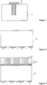
- Figure 1 illustrates a schematic diagram of a capacitor in an image sensor.
- the capacitor includes a semiconductor substrate 100.
- the semiconductor substrate 100 includes a trench region and a body region adjacent to the trench region. Trenches are formed in the semiconductor substrate 100 in the trench region.
- the capacitor also includes a dielectric layer 101 and a conductive layer 102, formed in the trenches and on portions of the semiconductor substrate 100.
- the dielectric layer 101 is formed on the sidewalls and at the bottom of the trenches, and on portions of the semiconductor substrate 100.
- the conductive layer 102 is formed on the dielectric layer 101 and filling the trenches.
- the conductive layer 102, the semiconductor substrate 100, and the dielectric layer 101 between them constitute the capacitor.
- the conductive layer 102 is above the surface of the semiconductor substrate 100 in the body region, and portions of the conductive layer 102 is exposed outside of the trenches.
- the conductive layer 102 is subjected to etching loss, thereby the electrical performance of the capacitor degrades.
- a method for forming a gate structure on the semiconductor substrate includes: forming a gate structure material layer on the semiconductor substrate in the trench region and in the body region; forming a planarization layer on the gate structure material layer; forming a patterned photoresist layer on the planarization layer; etching the gate structure material layer and the planarization layer on the semiconductor substrate in the trench region and in the body region by using the patterned photoresist layer as an etch mask to form the gate structure in the body region and to remove the gate structure material layer on the semiconductor substrate in the body region; and removing the planarization layer and the patterned photoresist layer.
- the gate structure material layer in the trench region is above the gate structure material layer in the body region.
- the gate structure material layer on the semiconductor substrate in the trench region may be first exposed.
- the conductive layer is subjected to etching loss, thereby the electrical performance of the capacitor degrades.
- the present invention provides a capacitor and fabrication methods thereof.
- Figure 10 illustrates an exemplary fabrication method for forming a capacitor consistent with various disclosed embodiments of the present invention
- Figures 2-9 illustrate semiconductor structures corresponding to certain stages of the exemplary fabrication method.
- a base substrate with certain structures may be provided (S101).
- Figure 2 illustrates a corresponding semiconductor structure.
- a base substrate 200 may be provided.
- the base substrate 200 may include a trench region I and a body region II adjacent to the trench region I.
- the base substrate in the trench region I may be used to form a first trench structure and a second trench structure.
- the base substrate 200 may be made of monocrystalline silicon. In another embodiment, the base substrate may be made of polysilicon or amorphous silicon. In certain embodiments, the base substrate may be made of germanium, silicon germanium, or gallium arsenide and other semiconductor materials.
- the surface of the base substrate 200 may have a first direction and a second direction intersecting the first direction.
- the first direction may be adapted to define a length direction of a subsequently formed first trench
- the second direction may be adapted to define a length direction of a subsequently formed second trench.
- the first direction may be perpendicular to the second direction.
- the angle between the first direction and the second direction may be an acute angle or an obtuse angle.
- the first trench structure and the second trench structure on the first trench structure may be formed in the base substrate 200 in the trench region I.
- a patterned mask structure may be formed (S102).
- Figures 3-4 illustrate a corresponding semiconductor structure.
- Figure 4 illustrates a top-view facing toward a patterned mask structure 210 on the basis of Figure 3, and Figure 3 illustrates a cross-sectional view along a line 'AA1' in Figure 4 .
- a patterned mask structure 210 may be formed on the base substrate 200.
- the patterned mask structure 210 may cover the base substrate 200 in the body region II and may expose portions of the base substrate 200 in the trench region I.
- the patterned mask structure 210 may include a mask opening structure.
- the mask opening structure may expose portions of the base substrate 200 in the trench region I.
- the mask opening structure may include a plurality of first mask openings 213, and one or more second mask openings 214 in a direction parallel to the surface of the base substrate 200.
- the second mask openings 214 may penetrate through the first mask openings 213, respectively.
- a length direction of the first mask openings 213 may be parallel to the first direction, and a length direction of the second mask openings 214 may be parallel to the second direction, perpendicular to the first direction.
- the mask opening structure may be used to define the position of a subsequently formed initial trench structure.
- the first mask openings 213 may be used to define subsequently formed first initial trenches, and the second mask openings 214 may be used to define subsequently formed second initial trenches.
- the number of the subsequently formed first initial trenches may be more than one, and the number of the subsequently formed second initial trenches may be one or more.
- the mask opening structure may include one first mask opening in the direction parallel to the surface of the base substrate 200.
- a subsequently formed first trench structure may include one first trench.
- the exemplary single first mask opening may be used to define a subsequently formed single first trench.
- the patterned mask structure 210 may be a stacked structure.
- the patterned mask structure 210 may include a first mask layer 211 formed on the base substrate 200 in the body region II and on portions of the base substrate 200 in the trench region I, and a second mask layer 212 formed on the first mask layer 211.
- the first mask layer 211 may be made of silicon nitride, silicon oxide, or silicon oxynitride, etc.
- the second mask layer 212 may be made of silicon nitride, silicon oxide, or silicon oxynitride, etc.
- the second mask layer 212 may be made of a material different from the first mask layer 211. When subsequently removing the second mask layer 212, the second mask layer 212 may have a higher etching selection rate over the first mask layer 211.
- a method for forming the mask structure 210 may include: forming a first initial mask layer on the base substrate 200; forming a second initial mask layer on the first initial mask layer; and forming a third initial mask layer on the second initial mask layer.
- the method may also include: forming a patterned photoresist layer on the third initial mask layer; and etching the third initial mask layer by using the patterned photoresist layer as an etch mask to form a third mask layer from the third initial mask layer.
- the third mask layer may include a third opening.
- the method may include etching the second initial mask layer and the first initial mask layer at the bottom of the third opening by using the patterned photoresist layer and the third mask layer as an etch mask, to form the second mask layer 212 from the second initial mask layer and the first mask layer 211 from the first initial mask layer.
- the second mask layer may include the second mask opening
- the first mask layer may include the first mask openings. The first mask openings and the second mask opening may form the mask opening structure.
- the third mask layer and the patterned photoresist layer when etching the second initial mask layer and the first initial mask layer at the bottom of the third opening, may be totally consumed and thus removed. In certain embodiments, after etching the second initial mask layer and the first initial mask layer at the bottom of the third opening, the third mask layer and the patterned photoresist layer may be retained. Then, the remaining third mask layer and the patterned photoresist layer may need to be removed, e.g., by an etching process. Alternatively, after etching the second initial mask layer and the first initial mask layer at the bottom of the third opening, the third mask layer may be retained. The third mask layer may be subsequently removed when removing the second mask layer.
- the third mask layer may be made of silicon, germanium, or germanium silicon, etc.
- the silicon, germanium, or germanium silicon may be in the form of polycrystalline or amorphous.
- the hardness of the third mask layer may be larger than the hardness of the second initial mask layer and the first initial mask layer.
- etching loss of the third mask layer may be small and morphology of the sidewall of the third mask layer may be as desired.
- morphology of the sidewall of the mask opening structure may be obtained as desired.
- the patterned mask structure may be a single-layer structure.
- the patterned mask structure may be made of silicon nitride, silicon oxide, silicon oxynitride, silicon, germanium or germanium silicon, etc.
- the silicon, germanium, or germanium silicon may be in the form of polycrystalline or amorphous.
- an interface layer may be formed between the patterned mask structure and the base substrate 200.
- the interface layer may be made of silicon oxide.
- a process for forming the interface layer may include an oxidation process.
- the interface layer may protect the base substrate 200 from etching damages when subsequently removing the first mask layer 211.
- the interface layer may be formed between the first mask layer 211 and the base substrate.
- the interface layer may serve as a stress buffer layer.
- an initial trench structure may be formed (S103).
- Figure 5 illustrates a corresponding semiconductor structure.
- an initial trench structure may be formed in the base substrate 200 in the trench region I by etching the base substrate 200 in the trench region I at the bottom of the mask opening structure using the patterned mask structure 210 as an etch mask.
- the initial trench structure may include a plurality of first initial trenches 221 and one or more second initial trenches (not illustrated). The second initial trenches may penetrate through the first initial trenches 221, respectively, in a direction parallel to the top surface of the base substrate 200.
- a length direction of the first initial trenches 221 may be parallel to the first direction, and a length direction of the second initial trenches may be parallel to the second direction.
- the first direction and the second direction may be across with each other, e.g., may be perpendicular with each other.
- a distance between the adjacent first initial trenches may be in a range of approximately 0.1 ⁇ m - 0.6 ⁇ m. If the distance between the adjacent first initial trenches is greater, such as greater than 0.6 ⁇ m, the total area of the first initial trenches 221 in the initial trench structure may become small, lowering the integration of capacitors. If the distance between the adjacent first initial trenches is smaller than 0.1 ⁇ m, the base substrate 200 in the trench region I between the adjacent first initial trenches 221 may be too thin. As a result, when forming the first initial trenches 221, the base substrate 200 in the trench region I between the adjacent first initial trenches 221 may be easily broken and dumped.
- a process for forming the initial trench structure by etching the base substrate 200 in the trench region I may include an anisotropic dry etching process.
- Parameters of the anisotropic dry etching process may include the following. Gases may include He, HBr, NF 3 , O 2 , HeO 2 , SiF 4 and Ar, He flow rate may be in a range of approximately 10 sccm - 22 sccm, HBr flow rate may be in a range of approximately 150 sccm - 230 sccm, NF 3 flow rate may be in a range of approximately 20 sccm - 40 sccm, O 2 flow rate may be in a range of approximately 4 sccm - 30 sccm, HeO 2 flow rate may be in a range of approximately 90 seem - 100 sccm, SiF 4 flow rate may be in a range of approximately 7 sccm - 10 sccm, Ar flow rate
- the gases may include NF 3 .
- the plasma formed by the NF 3 may react with the base substrate 200 to form a polymerization by-product.
- the polymerization by-product may be easily adsorbed on the sidewall of the initial trench structure.
- the polymerization by-product may protect the sidewall of the initial trench structure from large etching loss.
- the initial trench structure may be formed by etching the base substrate 200 in the trench region I using the above-described parameters, such that the verticality between the sidewall of the initial trench structure and the top surface of the base substrate may be high.
- the interface layer in the trench region I may also be etched.
- the initial trench structure may also penetrate through the interface layer.
- the area of the patterned mask structure 210 between the adjacent first mask openings 213, and between the adjacent first mask opening 213 and the second mask opening 214 may be small.
- the patterned mask structure 210 between the first mask opening 213 and an adjacent second mask opening 214 may be referred to a corner area including an intersection where the first mask opening 213 and the adjacent second mask opening intersect, along with surrounding areas of the intersection.
- the etching loss of the patterned mask structure 210 in the trench region I may be large.
- the top surface of the patterned mask structure 210 in the trench region I may be lower than the top surface of the patterned mask structure 210 in the body region II.
- a first trench structure and a second trench structure may be formed (S104).
- Figure 6 illustrates a corresponding semiconductor structure.
- a first trench structure and a second trench structure may be formed by removing portions of the base substrate 200 in the trench region I along the direction perpendicular to the top surface of the base substrate 200.
- portions of the base substrate 200 in the trench region I between the adjacent first initial trenches 221 (illustrated in Figure 5 ) and between the first initial trench 221 and the second initial trench may be removed along the direction perpendicular to the top surface of the base substrate 200.
- the base substrate between the first initial trench 221 and an adjacent second initial trench may be referred to a corner area including an intersection where the first initial trench 221 and the adjacent second initial trench intersect, along with surrounding areas of the intersection.
- the second trench structure may be formed on the first trench structure.
- the first trench structure may include a plurality of first trenches 230, and one or more second trenches.
- the second trenches may penetrate the first trenches 230, respectively, along a direction parallel to the top surface of the base substrate 200.
- a length direction of the first trenches 230 may be parallel to the first direction, and a length direction of the second trenches may be parallel to the second direction.
- the top surface of the base substrate 200 in the trench region I between the adjacent first initial trenches 221 and between the first initial trench 221 and the second initial trench may be lower than the top surface of the base substrate 200 in the body region II.
- the first mask layer 211 and the second mask layer 212 on the base substrate 200 in the trench region I, and the second mask layer 212 on the base substrate 200 in the body region II may be removed .
- a process for removing portions of the base substrate 200 in the trench region I between the adjacent first initial trenches 221 and between the first initial trench 221 and the second initial trench may include an etching process, such as a dry etching process and/or a wet etching process.
- the process for removing portions of the base substrate 200 in the trench region I between the adjacent first initial trenches 221 and between the first initial trench 221 and the second initial trench may include the dry etching process. Parameters of the dry etching process may include the following.
- Gases may include C 4 F 8 , CHF 3 , C 4 F 6 , O 2 , Ar and CO
- C 4 F 8 flow rate may be in a range of approximately 50 sccm - 100 sccm
- CHF 3 flow rate may be in a range of approximately 50 sccm - 200 sccm
- C 4 F 6 flow rate may be in a range of approximately 30 sccm - 80 sccm
- O 2 flow rate may be in a range of approximately 10 sccm - 30 sccm
- Ar flow rate may be in a range of approximately 500 sccm - 1000 sccm
- CO flow rate may be in a range of approximately 300 sccm - 800 sccm
- a chamber pressure may be in a range of approximately 30 mtorr- 70 mtorr
- a bias RF power may be in a range of approximately 800 watts - 2000 watts.
- the first mask layer 211 may be retained on the top surface of the base substrate 200 in the body region II.
- the patterned mask structure on the base substrate in the trench region and in the body region may be removed.
- the patterned mask structure on the base substrate in the trench region and in the body region may be removed. Then, portions of the base substrate in the trench region between the adjacent first initial trenches and between the first initial trench and the second initial trench may be removed.
- a method for forming the first trench structure and the second trench structure may include: forming a patterned mask layer, where the patterned mask layer may cover the base substrate in the body region and may expose the base substrate in the trench region; performing an anisotropic etching process on the base substrate in the trench region by using the patterned mask layer as a mask to form the first trench structure and the second trench structure on the first trench structure; and removing the patterned mask layer.
- an electrode layer may be formed (S105).
- Figure 7 illustrates a corresponding semiconductor structure.
- a dielectric layer 239 may be formed in the first trench structure, and an electrode layer 240 may be formed on the dielectric layer.
- the dielectric layer may be formed on the sidewall surface and bottom surface of the first trench structure.
- the dielectric layer 239 may be made of silicon oxide, or silicon nitride, etc.
- the electrode layer 240 may be made of polysilicon.
- a method for forming the dielectric layer and the electrode layer 240 may include: forming the dielectric layer on the sidewall surface and bottom surface of the first trench structure; forming an initial electrode layer (not illustrated) on the dielectric layer and on the base substrate 200, where the initial electrode layer may be formed in the first trench structure and in the second trench structure; and removing the initial electrode layer on the base substrate 200 and in the second trench structure to form the electrode layer 240.
- the dielectric layer may also be formed on the sidewall of the second trench structure.
- a process for forming the dielectric layer may include an oxidation process.
- a process for forming the initial electrode layer may include a deposition process, such as a high density plasma chemical vapor deposition process, a high aspect ratio deposition process, or a plasma enhanced chemical vapor deposition process, etc.
- a process for removing the initial electrode layer on the base substrate 200 and in the second trench structure may include a back-etching process.
- the first mask layer 211 may protect the top surface of the base substrate 200 from etching loss.
- an isolation layer may be formed (S106).
- Figure 8 illustrates a corresponding semiconductor structure.
- an isolation layer 250 may be formed to fill the second trench structure.
- the isolation layer 250 may be made of silicon oxide.
- a method for forming the isolation layer 250 may include: forming an initial isolation layer in the second trench structure and on the base substrate in the body region II; and removing the initial isolation layer on the base substrate 200 in the body region II to form the isolation layer 250.
- the initial isolation layer may be formed in the second trench structure and on the first mask layer 211.
- the initial isolation layer on the first mask layer 211 may be removed to form the isolation layer 250.
- the top surface of the isolation layer 250 may be above the top surface of the base substrate 200 in the body region II. In certain embodiments, the top surface of the isolation layer may be coplanar with the top surface of the base substrate in the body region.
- a process for forming the initial isolation layer may include a deposition process, such as a plasma chemical vapor deposition process, a low pressure chemical vapor deposition process, or a sub-atmosphere chemical vapor deposition process, etc.
- a process for removing the initial isolation layer on the base substrate 200 in the body region II may include a planarization process, such as a chemical mechanical polishing process.
- the first mask layer 211 may be exposed.
- the first mask layer 211 may protect the top surface of the base substrate 200 from etching loss.
- the first mask layer may be removed (S107).
- Figure 9 illustrates a corresponding semiconductor structure.
- the first mask layer 211 (illustrated in Figure 8 ) may be removed.
- a process for removing the first mask layer 211 may include a dry etching process, or a wet etching process, etc.
- an etching selection ratio of the first mask layer 211 to the isolation layer 250 may be in a range of approximately 10 - 20.
- the method for forming the capacitor may also include forming a conductive plug penetrating through the isolation layer 250.
- the conductive plug may be connected to the electrode layer 240.
- One end of the conductive plug may be connected to the electrode layer 240, and the other end of the conductive plug may be electrically connected to an interconnection structure above the capacitor.
- the first trench structure and the second trench structure on the first trench structure may be formed in the base substrate in the trench region.
- the dielectric layer and the electrode layer on the dielectric layer may be formed in the first trench structure.
- the electrode layer, the dielectric layer and the base substrate may form the capacitor.
- the isolation layer may be formed on the dielectric layer and on the electrode layer, and the bottom surface of the isolation layer may be lower than the top surface of the base substrate in the body region. Therefore, the isolation layer may protect the dielectric layer and the electrode layer. As a result, the electrode layer may not be affected during the subsequent processes, and the electrical performance of the capacitor may be improved.
- a method for forming an image sensor circuit is also provided in the present invention.
- the method may include forming a capacitor.
- the capacitor may be formed by the methods in the above-described embodiments for forming a capacitor.
- the base substrate may include a plurality of body regions, and trench regions between the adjacent body regions.
- the method for forming the image sensor circuit may also include forming body devices on the base substrate in the body regions, respectively.
- the isolation layer and the dielectric layer may be adapted to isolate the adjacent body devices.
- the method for forming the image sensor circuit consistent with disclosed embodiments may include the methods in the above-described embodiments for forming the capacitor, such that the electrical performance of the image sensor may be improved.
- the capacitor may include a base substrate 200.
- the base substrate 200 may include a trench region I and a body region II adjacent to the trench region I.
- the capacitor may also include a first trench structure and a second trench structure on the first trench structure in the base substrate 200 in the trench region I.
- the capacitor may include a dielectric layer 239 and an electrode layer 240 in the first trench structure.
- the dielectric layer 239 may be formed on a sidewall surface and a bottom surface of the first trench structure, and the electrode layer 240 may be formed on the dielectric layer.
- the capacitor may include an isolation layer 250 filling the second trench structure.
- the isolation structure 250 may be formed on the dielectric layer 239 and on the electrode layer 240.
- the isolation layer 250 may be made of silicon oxide.
- the top surface of the isolation layer 250 may be above the top surface of the base substrate 200 in the body region II. In certain embodiment, the top surface of the isolation layer may be coplanar with the top surface of the base substrate in the body region.
- the dielectric layer may be made of silicon oxide, or silicon nitride, etc.
- the electrode layer may be made of polysilicon.
- the first trench structure and the second trench structure on the first trench structure may be formed in the base substrate in the trench region.
- the dielectric layer and the electrode layer on the dielectric layer may be formed in the first trench structure.
- the electrode layer, the dielectric layer and the base substrate may form the capacitor.
- the isolation layer may be formed in the second trench structure and on the dielectric layer and on the electrode layer, and the bottom surface of the isolation layer may be lower than the top surface of the base substrate in the body region. Therefore, the isolation layer may protect the dielectric layer and the electrode layer. As a result, the electrode layer may not be affected during the subsequent processes, and the electrical performance of the capacitor may be improved.
- an image sensor circuit is also provided in the present invention.
- the image sensor circuit may include a capacitor consistent with above-described embodiments.
- the base substrate may include a plurality of body regions, and trench regions between the adjacent body regions.
- the image sensor circuit may also include body devices, formed on the base substrate in the body regions, respectively.
- the isolation layer and the dielectric layer may be adapted to isolate the adjacent body devices.
- the image sensor circuit consistent with disclosed embodiments may include the above-described capacitor, such that the electrical performance of the image sensor may be improved.
- the disclosed capacitor may include electrode layers lower than the base substrate in the body region to protect the electrode layers from being damaged during subsequent processes. Since the capacitor may have been embedded in the shallow trench isolation (STI), the damage concerns on the capacitor in the STI may be avoided. In one embodiment, the total capacitance and leakage of the capacitor in the present invention may be comparable with the conventional capacitors.
- the fabrication method consistent with disclosed embodiments at least two masks and the related photolithography and etching steps for removing the patterned mask layer and the conductive layer in the body region may be saved, and the production cost of the capacitor may be lowered.
- the fabrication method consistent with disclosed embodiments may provide better process control, and may not have impact on other devices.
- the capacitor in the present invention may be used in data storage, and in CIS process for global shutter application to improve image distortion and lag.
- the first trench structure and the second trench structure on the first trench structure may be formed in the base substrate in the trench region.
- the dielectric layer and the electrode layer on the dielectric layer may be formed in the first trench structure.
- the electrode layer, the dielectric layer and the base substrate may form the capacitor.
- the isolation layer may be formed on the dielectric layer and on the electrode layer, and the bottom surface of the isolation layer may be lower than the top surface of the base substrate in the body region. Therefore, the isolation layer may protect the dielectric layer and the electrode layer. As a result, the electrode layer may not be affected during the subsequent processes, and the electrical performance of the capacitor may be improved.
- the method for forming the image sensor circuit consistent with disclosed embodiments may include the methods in the above-described embodiments for forming the capacitor, such that the electrical performance of the image sensor may be improved.
- the first trench structure and the second trench structure on the first trench structure may be formed in the base substrate in the trench region.
- the dielectric layer and the electrode layer on the dielectric layer may be formed in the first trench structure.
- the electrode layer, the dielectric layer and the base substrate may form the capacitor.
- the isolation layer may be formed in the second trench structure and on the dielectric layer and on the electrode layer, and the bottom surface of the isolation layer may be lower than the top surface of the base substrate in the body region. Therefore, the isolation layer may protect the dielectric layer and the electrode layer. As a result, the electrode layer may not be affected during the subsequent processes, and the electrical performance of the capacitor may be improved.
- the image sensor circuit consistent with disclosed embodiments may include the above-described capacitor, such that the electrical performance of the image sensor may be improved.
Landscapes
- Engineering & Computer Science (AREA)
- Power Engineering (AREA)
- Microelectronics & Electronic Packaging (AREA)
- Solid State Image Pick-Up Elements (AREA)
- Semiconductor Integrated Circuits (AREA)
Abstract
Description
- This application claims the priority of Chinese patent application No.
201611198711.X, filed on December 22, 2016 - The present invention generally relates to the field of semiconductor manufacturing and, more particularly, relates to a capacitor, image sensor circuit and fabrication methods thereof.
- An image sensor is a device that converts optical information into electrical information. At present, the image sensor mainly includes a charge coupled device (CCD) image sensor and a complementary metal-oxide semiconductor (CMOS) image sensor. Compared to the CCD image sensor, the CMOS image sensor (CIS) has wider applications. A CMOS image sensor circuit includes photosensitive components, transistors, capacitors and other structures.
- However, the electrical performance of the conventional capacitor is poor and needs to be improved.
- It is an object of the present invention to provide a method for fabricating a capacitor, a method for fabricating an image sensor, an capacitor, and an image sensor, in particular by which or in which the electrical performance of the capacitor is improved.
- The object is achieved by the features of the respective independent claims. Further embodiments are defined in the respective dependent claims.
- A first aspect of the present invention provides a method for fabricating a capacitor. The method includes providing a base substrate including a trench region and a body region adjacent to the trench region. The method also includes forming a first trench structure and a second trench structure on the first trench structure, in the base substrate in the trench region. In addition, the method includes forming a dielectric layer on a sidewall surface and a bottom surface of the first trench structure and an electrode layer on the dielectric layer in the first trench structure. Further, the method includes forming an isolation layer filling the second trench structure.
- Preferably, the first trench structure includes one first trench.
- Preferably, wherein forming the first trench structure and the second trench structure includes: forming a patterned mask layer, wherein the patterned mask layer covers the base substrate in the body region and exposes the base substrate in the trench region; performing an anisotropic etching process on the base substrate in the trench region by using the patterned mask layer as a mask to form the first trench structure and the second trench structure; and removing the patterned mask layer.
- Preferably, the first trench structure includes a plurality of first trenches, and one or more second trenches, wherein the second trenches respectively penetrate each first trench along a direction parallel to a top surface of the base substrate.
- Preferably, forming the first trench structure and the second trench structure includes: forming an initial trench structure in the base substrate in the trench region, wherein the initial trench structure includes a plurality of first initial trenches and one or more second initial trenches, and the second initial trenches respectively penetrate each first initial trenches along the direction parallel to the top surface of the base substrate; and removing portions of the base substrate in the trench region along a direction perpendicular to the top surface of the base substrate to form the first trench structure and the second trench structure.
- Preferably, before forming the initial trench structure, the method further includes: forming a patterned mask structure on the base substrate, wherein the patterned mask structure covers the base substrate in the body region and exposes portions of the base substrate in the trench region; and etching the base substrate in the trench region, using the patterned mask structure as an etch mask to form the initial trench structure.
- Preferably, the patterned mask structure includes a first mask layer on the base substrate in the body region and on portions of the base substrate in the trench region, and a second mask layer on the first mask layer.
- Preferably, the first mask layer is made of one of silicon nitride, silicon oxide, and silicon oxynitride; the second mask layer is made of one of silicon nitride, silicon oxide, and silicon oxynitride; and the second mask layer is made of a material different from the first mask layer.
- Preferably, the method includes: removing the first mask layer and the second mask layer above the base substrate in the trench region and the second mask layer above the base substrate in the body region when removing portions of the base substrate in the trench region; retaining the first mask layer on the top surface of the base substrate in the body region after forming the first trench structure and the second trench structure; and removing the first mask layer after forming the isolation layer.
- Preferably, forming the isolation layer includes: forming an initial isolation layer in the second trench structure and on the first mask layer; and removing the initial isolation layer on the first mask layer to form the isolation layer.
- Preferably, the isolation layer is made of silicon oxide.
- Preferably, forming the dielectric layer and the electrode layer includes: forming the dielectric layer on the sidewall surface and the bottom surface of the first trench structure; forming an initial electrode layer on the dielectric layer and the base substrate and in the first trench structure and the second trench structure; and removing the initial electrode layer on the base substrate and in the second trench structure to form the electrode layer.
- Preferably, the dielectric layer is made of one of silicon oxide and silicon nitride.
- Preferably, the electrode layer is made of polysilicon.
- Preferably, the method further includes: forming a conductive plug, penetrating the isolation layer and connected to the electrode layer.
- A second aspect of the present invention provides a method for fabricating an image sensor circuit, which comprises at least one capacitor, wherein the capacitor is formed by a method according to the first aspect of the present invention.
- Accordingly, the method for fabricating the image sensor circuit includes forming at least one capacitor, wherein a method for forming the capacitor includes providing a base substrate including a trench region and a body region adjacent to the trench region. The method for forming the capacitor also includes forming a first trench structure and a second trench structure on the first trench structure, in the base substrate in the trench region. In addition, the method for forming the capacitor includes forming a dielectric layer on a sidewall surface and a bottom surface of the first trench structure and an electrode layer on the dielectric layer in the first trench structure. Further, the method for forming the capacitor includes forming an isolation layer filling the second trench structure.
- Preferably, the method for fabricating an image sensor further includes: forming body devices on the base substrate in the body region, wherein the isolation layer and the dielectric layer isolate the adjacent body devices.
- A third aspect of the present invention provides a capacitor. The capacitor includes a base substrate including a trench region and a body region adjacent to the trench region. The capacitor also includes a first trench structure and a second trench structure on the first trench structure, in the base substrate in the trench region. In addition, the capacitor includes a dielectric layer on a sidewall surface and a bottom surface of the first trench structure and an electrode layer on the dielectric layer in the first trench structure. Further, the capacitor includes an isolation layer filling the second trench structure and on the dielectric layer and the electrode layer.
- Preferably, the isolation layer is made of silicon oxide.
- Preferably, the dielectric layer is made of one of silicon oxide and silicon nitride.
- Preferably, the electrode layer is made of polysilicon.
- Preferably, a top surface of the isolation layer is above a top surface of the base substrate in the body region.
- Preferably, a conductive plug, penetrating the isolation layer and connected to the electrode layer.
- A forth aspect of the present invention provides an image sensor including at least one capacitor according to the third aspect of the present invention.
- A capacitor according to the third aspect of the present invention may be obtained by a method according to the third aspect of the present invention.
- A image sensor according to the forth aspect of the present invention may be obtained by a method according to the second aspect of the present invention.
- Other aspects of the present invention can be understood by those skilled in the art in light of the description, the claims, and the drawings of the present invention.
-
-
Figure 1 illustrates a schematic diagram of a capacitor in an image sensor; -
Figures 2-9 illustrate semiconductor structures corresponding to certain stages for forming an exemplary capacitor consistent with various disclosed embodiments of the present invention; and -
Figure 10 illustrates an exemplary fabrication method for forming a capacitor consistent with various disclosed embodiments of the present invention. - Reference will now be made in detail to exemplary embodiments of the invention, which are illustrated in the accompanying drawings. Wherever possible, the same reference numbers will be used throughout the drawings to refer to the same or the alike parts.
-
Figure 1 illustrates a schematic diagram of a capacitor in an image sensor. Referring toFigure 1 , the capacitor includes asemiconductor substrate 100. Thesemiconductor substrate 100 includes a trench region and a body region adjacent to the trench region. Trenches are formed in thesemiconductor substrate 100 in the trench region. The capacitor also includes adielectric layer 101 and aconductive layer 102, formed in the trenches and on portions of thesemiconductor substrate 100. Thedielectric layer 101 is formed on the sidewalls and at the bottom of the trenches, and on portions of thesemiconductor substrate 100. Theconductive layer 102 is formed on thedielectric layer 101 and filling the trenches. Theconductive layer 102, thesemiconductor substrate 100, and thedielectric layer 101 between them constitute the capacitor. - In the above capacitor, the
conductive layer 102 is above the surface of thesemiconductor substrate 100 in the body region, and portions of theconductive layer 102 is exposed outside of the trenches. When performing other processes, theconductive layer 102 is subjected to etching loss, thereby the electrical performance of the capacitor degrades. - For example, a method for forming a gate structure on the semiconductor substrate includes: forming a gate structure material layer on the semiconductor substrate in the trench region and in the body region; forming a planarization layer on the gate structure material layer; forming a patterned photoresist layer on the planarization layer; etching the gate structure material layer and the planarization layer on the semiconductor substrate in the trench region and in the body region by using the patterned photoresist layer as an etch mask to form the gate structure in the body region and to remove the gate structure material layer on the semiconductor substrate in the body region; and removing the planarization layer and the patterned photoresist layer.
- Because the conductive layer is above the surface of the semiconductor substrate in the body region, the gate structure material layer in the trench region is above the gate structure material layer in the body region. When etching the gate structure material layer and the planarization layer on the semiconductor substrate in the trench region and in the body region, the gate structure material layer on the semiconductor substrate in the trench region may be first exposed. When removing the gate structure material layer on the semiconductor substrate in the trench region, only portions of a height of the gate structure material layer on the semiconductor substrate in the body region is etched, or the gate structure material layer on the semiconductor substrate in the body region is not exposed. After forming the gate structure, the conductive layer is subjected to etching loss, thereby the electrical performance of the capacitor degrades.
- The present invention provides a capacitor and fabrication methods thereof.
Figure 10 illustrates an exemplary fabrication method for forming a capacitor consistent with various disclosed embodiments of the present invention; andFigures 2-9 illustrate semiconductor structures corresponding to certain stages of the exemplary fabrication method. - As shown in
Figure 10 , at the beginning of the fabrication method, a base substrate with certain structures may be provided (S101).Figure 2 illustrates a corresponding semiconductor structure. - Referring to
Figure 2 , abase substrate 200 may be provided. Thebase substrate 200 may include a trench region I and a body region II adjacent to the trench region I. The base substrate in the trench region I may be used to form a first trench structure and a second trench structure. - In one embodiment, the
base substrate 200 may be made of monocrystalline silicon. In another embodiment, the base substrate may be made of polysilicon or amorphous silicon. In certain embodiments, the base substrate may be made of germanium, silicon germanium, or gallium arsenide and other semiconductor materials. - In one embodiment, the surface of the
base substrate 200 may have a first direction and a second direction intersecting the first direction. The first direction may be adapted to define a length direction of a subsequently formed first trench, and the second direction may be adapted to define a length direction of a subsequently formed second trench. In one embodiment, the first direction may be perpendicular to the second direction. In certain embodiments, the angle between the first direction and the second direction may be an acute angle or an obtuse angle. - Then, the first trench structure and the second trench structure on the first trench structure may be formed in the
base substrate 200 in the trench region I. - Returning to
Figure 10 , after forming the base substrate, a patterned mask structure may be formed (S102).Figures 3-4 illustrate a corresponding semiconductor structure. -
Figure 4 illustrates a top-view facing toward apatterned mask structure 210 on the basis ofFigure 3, and Figure 3 illustrates a cross-sectional view along a line 'AA1' inFigure 4 . Referring toFigures 3-4 , apatterned mask structure 210 may be formed on thebase substrate 200. The patternedmask structure 210 may cover thebase substrate 200 in the body region II and may expose portions of thebase substrate 200 in the trench region I. - The patterned
mask structure 210 may include a mask opening structure. The mask opening structure may expose portions of thebase substrate 200 in the trench region I. In one embodiment, the mask opening structure may include a plurality offirst mask openings 213, and one or moresecond mask openings 214 in a direction parallel to the surface of thebase substrate 200. Thesecond mask openings 214 may penetrate through thefirst mask openings 213, respectively. A length direction of thefirst mask openings 213 may be parallel to the first direction, and a length direction of thesecond mask openings 214 may be parallel to the second direction, perpendicular to the first direction. The mask opening structure may be used to define the position of a subsequently formed initial trench structure. Thefirst mask openings 213 may be used to define subsequently formed first initial trenches, and thesecond mask openings 214 may be used to define subsequently formed second initial trenches. Correspondingly, the number of the subsequently formed first initial trenches may be more than one, and the number of the subsequently formed second initial trenches may be one or more. - In certain embodiments, the mask opening structure may include one first mask opening in the direction parallel to the surface of the
base substrate 200. Correspondingly, a subsequently formed first trench structure may include one first trench. The exemplary single first mask opening may be used to define a subsequently formed single first trench. - In one embodiment, the patterned
mask structure 210 may be a stacked structure. The patternedmask structure 210 may include afirst mask layer 211 formed on thebase substrate 200 in the body region II and on portions of thebase substrate 200 in the trench region I, and asecond mask layer 212 formed on thefirst mask layer 211. - In one embodiment, the
first mask layer 211 may be made of silicon nitride, silicon oxide, or silicon oxynitride, etc. Thesecond mask layer 212 may be made of silicon nitride, silicon oxide, or silicon oxynitride, etc. Thesecond mask layer 212 may be made of a material different from thefirst mask layer 211. When subsequently removing thesecond mask layer 212, thesecond mask layer 212 may have a higher etching selection rate over thefirst mask layer 211. - A method for forming the
mask structure 210 may include: forming a first initial mask layer on thebase substrate 200; forming a second initial mask layer on the first initial mask layer; and forming a third initial mask layer on the second initial mask layer. The method may also include: forming a patterned photoresist layer on the third initial mask layer; and etching the third initial mask layer by using the patterned photoresist layer as an etch mask to form a third mask layer from the third initial mask layer. The third mask layer may include a third opening. Further, the method may include etching the second initial mask layer and the first initial mask layer at the bottom of the third opening by using the patterned photoresist layer and the third mask layer as an etch mask, to form thesecond mask layer 212 from the second initial mask layer and thefirst mask layer 211 from the first initial mask layer. The second mask layer may include the second mask opening, and the first mask layer may include the first mask openings. The first mask openings and the second mask opening may form the mask opening structure. - In one embodiment, when etching the second initial mask layer and the first initial mask layer at the bottom of the third opening, the third mask layer and the patterned photoresist layer may be totally consumed and thus removed. In certain embodiments, after etching the second initial mask layer and the first initial mask layer at the bottom of the third opening, the third mask layer and the patterned photoresist layer may be retained. Then, the remaining third mask layer and the patterned photoresist layer may need to be removed, e.g., by an etching process. Alternatively, after etching the second initial mask layer and the first initial mask layer at the bottom of the third opening, the third mask layer may be retained. The third mask layer may be subsequently removed when removing the second mask layer.
- In one embodiment, the third mask layer may be made of silicon, germanium, or germanium silicon, etc. The silicon, germanium, or germanium silicon may be in the form of polycrystalline or amorphous.
- The hardness of the third mask layer may be larger than the hardness of the second initial mask layer and the first initial mask layer. When etching the second initial mask layer and the first initial mask layer at the bottom of the third opening by using the third mask layer as an etch mask, etching loss of the third mask layer may be small and morphology of the sidewall of the third mask layer may be as desired. Correspondingly, morphology of the sidewall of the mask opening structure may be obtained as desired.
- In certain embodiments, the patterned mask structure may be a single-layer structure. The patterned mask structure may be made of silicon nitride, silicon oxide, silicon oxynitride, silicon, germanium or germanium silicon, etc. The silicon, germanium, or germanium silicon may be in the form of polycrystalline or amorphous.
- In one embodiment, an interface layer may be formed between the patterned mask structure and the
base substrate 200. The interface layer may be made of silicon oxide. A process for forming the interface layer may include an oxidation process. The interface layer may protect thebase substrate 200 from etching damages when subsequently removing thefirst mask layer 211. When thefirst mask layer 211 is made of silicon nitride, the interface layer may be formed between thefirst mask layer 211 and the base substrate. The interface layer may serve as a stress buffer layer. - Returning to
Figure 10 , after forming the mask opening structure, an initial trench structure may be formed (S103).Figure 5 illustrates a corresponding semiconductor structure. - Referring to
Figure 5 , an initial trench structure may be formed in thebase substrate 200 in the trench region I by etching thebase substrate 200 in the trench region I at the bottom of the mask opening structure using the patternedmask structure 210 as an etch mask. The initial trench structure may include a plurality of firstinitial trenches 221 and one or more second initial trenches (not illustrated). The second initial trenches may penetrate through the firstinitial trenches 221, respectively, in a direction parallel to the top surface of thebase substrate 200. - In one embodiment, a length direction of the first
initial trenches 221 may be parallel to the first direction, and a length direction of the second initial trenches may be parallel to the second direction. The first direction and the second direction may be across with each other, e.g., may be perpendicular with each other. - In one embodiment, a distance between the adjacent first initial trenches may be in a range of approximately 0.1 µm - 0.6 µm. If the distance between the adjacent first initial trenches is greater, such as greater than 0.6 µm, the total area of the first
initial trenches 221 in the initial trench structure may become small, lowering the integration of capacitors. If the distance between the adjacent first initial trenches is smaller than 0.1 µm, thebase substrate 200 in the trench region I between the adjacent firstinitial trenches 221 may be too thin. As a result, when forming the firstinitial trenches 221, thebase substrate 200 in the trench region I between the adjacent firstinitial trenches 221 may be easily broken and dumped. - In one embodiment, a process for forming the initial trench structure by etching the
base substrate 200 in the trench region I may include an anisotropic dry etching process. Parameters of the anisotropic dry etching process may include the following. Gases may include He, HBr, NF3, O2, HeO2, SiF4 and Ar, He flow rate may be in a range of approximately 10 sccm - 22 sccm, HBr flow rate may be in a range of approximately 150 sccm - 230 sccm, NF3 flow rate may be in a range of approximately 20 sccm - 40 sccm, O2 flow rate may be in a range of approximately 4 sccm - 30 sccm, HeO2 flow rate may be in a range of approximately 90 seem - 100 sccm, SiF4 flow rate may be in a range of approximately 7 sccm - 10 sccm, Ar flow rate may be in a range of approximately 100 sccm - 200 sccm, a source RF power may be in a range of approximately 200 watts - 1000 watts, a bias RF power may be in a range of approximately 300 watts - 1200 watts, and a chamber pressure may be in a range of approximately 80 mtorr - 250 mtorr. - When forming the initial trench structure by etching the
base substrate 200 in the trench region I, the gases may include NF3. The plasma formed by the NF3 may react with thebase substrate 200 to form a polymerization by-product. The polymerization by-product may be easily adsorbed on the sidewall of the initial trench structure. The polymerization by-product may protect the sidewall of the initial trench structure from large etching loss. - In one embodiment, the initial trench structure may be formed by etching the
base substrate 200 in the trench region I using the above-described parameters, such that the verticality between the sidewall of the initial trench structure and the top surface of the base substrate may be high. - In one embodiment, when etching the
base substrate 200 in the trench region I, the interface layer in the trench region I may also be etched. Correspondingly, the initial trench structure may also penetrate through the interface layer. - The area of the patterned
mask structure 210 between the adjacentfirst mask openings 213, and between the adjacentfirst mask opening 213 and the second mask opening 214 may be small. The patternedmask structure 210 between thefirst mask opening 213 and an adjacent second mask opening 214 may be referred to a corner area including an intersection where thefirst mask opening 213 and the adjacent second mask opening intersect, along with surrounding areas of the intersection. Thus the etching loss of the patternedmask structure 210 in the trench region I may be large. After forming the initial trench structure, the top surface of the patternedmask structure 210 in the trench region I may be lower than the top surface of the patternedmask structure 210 in the body region II. - Returning to
Figure 10 , after forming the initial trench structure, a first trench structure and a second trench structure may be formed (S104).Figure 6 illustrates a corresponding semiconductor structure. - Referring to
Figure 6 , a first trench structure and a second trench structure may be formed by removing portions of thebase substrate 200 in the trench region I along the direction perpendicular to the top surface of thebase substrate 200. In one embodiment, portions of thebase substrate 200 in the trench region I between the adjacent first initial trenches 221 (illustrated inFigure 5 ) and between the firstinitial trench 221 and the second initial trench may be removed along the direction perpendicular to the top surface of thebase substrate 200. The base substrate between the firstinitial trench 221 and an adjacent second initial trench may be referred to a corner area including an intersection where the firstinitial trench 221 and the adjacent second initial trench intersect, along with surrounding areas of the intersection. The second trench structure may be formed on the first trench structure. - In one embodiment, the first trench structure may include a plurality of
first trenches 230, and one or more second trenches. The second trenches may penetrate thefirst trenches 230, respectively, along a direction parallel to the top surface of thebase substrate 200. A length direction of thefirst trenches 230 may be parallel to the first direction, and a length direction of the second trenches may be parallel to the second direction. - In one embodiment, after removing portions of the
base substrate 200 in the trench region I between the adjacent firstinitial trenches 221 and between the firstinitial trench 221 and the second initial trench, the top surface of thebase substrate 200 in the trench region I between the adjacent firstinitial trenches 221 and between the firstinitial trench 221 and the second initial trench may be lower than the top surface of thebase substrate 200 in the body region II. - In one embodiment, when removing portions of the
base substrate 200 in the trench region I between the adjacent firstinitial trenches 221 and between the firstinitial trench 221 and the second initial trench, thefirst mask layer 211 and thesecond mask layer 212 on thebase substrate 200 in the trench region I, and thesecond mask layer 212 on thebase substrate 200 in the body region II may be removed . - A process for removing portions of the
base substrate 200 in the trench region I between the adjacent firstinitial trenches 221 and between the firstinitial trench 221 and the second initial trench may include an etching process, such as a dry etching process and/or a wet etching process. In one embodiment, the process for removing portions of thebase substrate 200 in the trench region I between the adjacent firstinitial trenches 221 and between the firstinitial trench 221 and the second initial trench may include the dry etching process. Parameters of the dry etching process may include the following. Gases may include C4F8, CHF3, C4F6, O2, Ar and CO, C4F8 flow rate may be in a range of approximately 50 sccm - 100 sccm, CHF3 flow rate may be in a range of approximately 50 sccm - 200 sccm, C4F6 flow rate may be in a range of approximately 30 sccm - 80 sccm, O2 flow rate may be in a range of approximately 10 sccm - 30 sccm, Ar flow rate may be in a range of approximately 500 sccm - 1000 sccm, CO flow rate may be in a range of approximately 300 sccm - 800 sccm, a chamber pressure may be in a range of approximately 30 mtorr- 70 mtorr, and a bias RF power may be in a range of approximately 800 watts - 2000 watts. - After forming the first trench structure and the second trench structure, the
first mask layer 211 may be retained on the top surface of thebase substrate 200 in the body region II. In certain embodiments, when removing portions of the base substrate in the trench region between the adjacent first initial trenches and between the first initial trench and the second initial trench, the patterned mask structure on the base substrate in the trench region and in the body region may be removed. - In certain embodiments, after forming the initial trench structure, the patterned mask structure on the base substrate in the trench region and in the body region may be removed. Then, portions of the base substrate in the trench region between the adjacent first initial trenches and between the first initial trench and the second initial trench may be removed.
- When the first trench structure includes one first trench, a method for forming the first trench structure and the second trench structure may include: forming a patterned mask layer, where the patterned mask layer may cover the base substrate in the body region and may expose the base substrate in the trench region; performing an anisotropic etching process on the base substrate in the trench region by using the patterned mask layer as a mask to form the first trench structure and the second trench structure on the first trench structure; and removing the patterned mask layer.
- Returning to
Figure 10 , after forming the first trench structure and the second trench structure, an electrode layer may be formed (S105).Figure 7 illustrates a corresponding semiconductor structure. - Referring to
Figure 7 , adielectric layer 239 may be formed in the first trench structure, and anelectrode layer 240 may be formed on the dielectric layer. The dielectric layer may be formed on the sidewall surface and bottom surface of the first trench structure. Thedielectric layer 239 may be made of silicon oxide, or silicon nitride, etc. Theelectrode layer 240 may be made of polysilicon. - A method for forming the dielectric layer and the
electrode layer 240 may include: forming the dielectric layer on the sidewall surface and bottom surface of the first trench structure; forming an initial electrode layer (not illustrated) on the dielectric layer and on thebase substrate 200, where the initial electrode layer may be formed in the first trench structure and in the second trench structure; and removing the initial electrode layer on thebase substrate 200 and in the second trench structure to form theelectrode layer 240. In one embodiment, the dielectric layer may also be formed on the sidewall of the second trench structure. - A process for forming the dielectric layer may include an oxidation process. A process for forming the initial electrode layer may include a deposition process, such as a high density plasma chemical vapor deposition process, a high aspect ratio deposition process, or a plasma enhanced chemical vapor deposition process, etc. A process for removing the initial electrode layer on the
base substrate 200 and in the second trench structure may include a back-etching process. - When removing the initial electrode layer on the
base substrate 200 and in the second trench structure, thefirst mask layer 211 may protect the top surface of thebase substrate 200 from etching loss. - Returning to
Figure 10 , after forming the electrode layer, an isolation layer may be formed (S106).Figure 8 illustrates a corresponding semiconductor structure. - Referring to
Figure 8 , after forming thedielectric layer 239 and theelectrode layer 240, anisolation layer 250 may be formed to fill the second trench structure. In one embodiment, theisolation layer 250 may be made of silicon oxide. - A method for forming the
isolation layer 250 may include: forming an initial isolation layer in the second trench structure and on the base substrate in the body region II; and removing the initial isolation layer on thebase substrate 200 in the body region II to form theisolation layer 250. - In one embodiment, the initial isolation layer may be formed in the second trench structure and on the
first mask layer 211. The initial isolation layer on thefirst mask layer 211 may be removed to form theisolation layer 250. - In one embodiment, the top surface of the
isolation layer 250 may be above the top surface of thebase substrate 200 in the body region II. In certain embodiments, the top surface of the isolation layer may be coplanar with the top surface of the base substrate in the body region. - A process for forming the initial isolation layer may include a deposition process, such as a plasma chemical vapor deposition process, a low pressure chemical vapor deposition process, or a sub-atmosphere chemical vapor deposition process, etc. A process for removing the initial isolation layer on the
base substrate 200 in the body region II may include a planarization process, such as a chemical mechanical polishing process. - In one embodiment, after removing the initial isolation layer on the
base substrate 200 in the body region II, thefirst mask layer 211 may be exposed. When removing the initial isolation layer on thebase substrate 200 in the body region II, thefirst mask layer 211 may protect the top surface of thebase substrate 200 from etching loss. - Returning to
Figure 10 , after forming the isolation layer, the first mask layer may be removed (S107).Figure 9 illustrates a corresponding semiconductor structure. - Referring to
Figure 9 , after forming theisolation layer 250, the first mask layer 211 (illustrated inFigure 8 ) may be removed. A process for removing thefirst mask layer 211 may include a dry etching process, or a wet etching process, etc. In one embodiment, when removing thefirst mask layer 211, an etching selection ratio of thefirst mask layer 211 to theisolation layer 250 may be in a range of approximately 10 - 20. - In one embodiment, the method for forming the capacitor may also include forming a conductive plug penetrating through the
isolation layer 250. The conductive plug may be connected to theelectrode layer 240. One end of the conductive plug may be connected to theelectrode layer 240, and the other end of the conductive plug may be electrically connected to an interconnection structure above the capacitor. - In the fabrication method for forming the capacitor consistent with disclosed embodiments, the first trench structure and the second trench structure on the first trench structure may be formed in the base substrate in the trench region. The dielectric layer and the electrode layer on the dielectric layer may be formed in the first trench structure. The electrode layer, the dielectric layer and the base substrate may form the capacitor. After forming the isolation layer in the second trench structure, the isolation layer may be formed on the dielectric layer and on the electrode layer, and the bottom surface of the isolation layer may be lower than the top surface of the base substrate in the body region. Therefore, the isolation layer may protect the dielectric layer and the electrode layer. As a result, the electrode layer may not be affected during the subsequent processes, and the electrical performance of the capacitor may be improved.
- Correspondingly, a method for forming an image sensor circuit is also provided in the present invention. The method may include forming a capacitor. The capacitor may be formed by the methods in the above-described embodiments for forming a capacitor.
- The base substrate may include a plurality of body regions, and trench regions between the adjacent body regions. The method for forming the image sensor circuit may also include forming body devices on the base substrate in the body regions, respectively. The isolation layer and the dielectric layer may be adapted to isolate the adjacent body devices.
- The method for forming the image sensor circuit consistent with disclosed embodiments may include the methods in the above-described embodiments for forming the capacitor, such that the electrical performance of the image sensor may be improved.
- Correspondingly, a capacitor is also provided in the present invention. Referring to
Figure 9 , the capacitor may include abase substrate 200. Thebase substrate 200 may include a trench region I and a body region II adjacent to the trench region I. The capacitor may also include a first trench structure and a second trench structure on the first trench structure in thebase substrate 200 in the trench region I. In addition, the capacitor may include adielectric layer 239 and anelectrode layer 240 in the first trench structure. Thedielectric layer 239 may be formed on a sidewall surface and a bottom surface of the first trench structure, and theelectrode layer 240 may be formed on the dielectric layer. Further, the capacitor may include anisolation layer 250 filling the second trench structure. Theisolation structure 250 may be formed on thedielectric layer 239 and on theelectrode layer 240. - In one embodiment, the
isolation layer 250 may be made of silicon oxide. The top surface of theisolation layer 250 may be above the top surface of thebase substrate 200 in the body region II. In certain embodiment, the top surface of the isolation layer may be coplanar with the top surface of the base substrate in the body region. In one embodiment, the dielectric layer may be made of silicon oxide, or silicon nitride, etc. The electrode layer may be made of polysilicon. - In the capacitor consistent with disclosed embodiments, the first trench structure and the second trench structure on the first trench structure may be formed in the base substrate in the trench region. The dielectric layer and the electrode layer on the dielectric layer may be formed in the first trench structure. The electrode layer, the dielectric layer and the base substrate may form the capacitor. The isolation layer may be formed in the second trench structure and on the dielectric layer and on the electrode layer, and the bottom surface of the isolation layer may be lower than the top surface of the base substrate in the body region. Therefore, the isolation layer may protect the dielectric layer and the electrode layer. As a result, the electrode layer may not be affected during the subsequent processes, and the electrical performance of the capacitor may be improved.
- Correspondingly, an image sensor circuit is also provided in the present invention. The image sensor circuit may include a capacitor consistent with above-described embodiments. In the image sensor circuit, the base substrate may include a plurality of body regions, and trench regions between the adjacent body regions. The image sensor circuit may also include body devices, formed on the base substrate in the body regions, respectively. The isolation layer and the dielectric layer may be adapted to isolate the adjacent body devices.
- The image sensor circuit consistent with disclosed embodiments may include the above-described capacitor, such that the electrical performance of the image sensor may be improved.
- Unlike a conventional capacitor having electrode layers above the semiconductor substrate, the disclosed capacitor may include electrode layers lower than the base substrate in the body region to protect the electrode layers from being damaged during subsequent processes. Since the capacitor may have been embedded in the shallow trench isolation (STI), the damage concerns on the capacitor in the STI may be avoided. In one embodiment, the total capacitance and leakage of the capacitor in the present invention may be comparable with the conventional capacitors. By using the fabrication method consistent with disclosed embodiments, at least two masks and the related photolithography and etching steps for removing the patterned mask layer and the conductive layer in the body region may be saved, and the production cost of the capacitor may be lowered. The fabrication method consistent with disclosed embodiments may provide better process control, and may not have impact on other devices. The capacitor in the present invention may be used in data storage, and in CIS process for global shutter application to improve image distortion and lag.
- In the fabrication method for forming the capacitor consistent with disclosed embodiments, the first trench structure and the second trench structure on the first trench structure may be formed in the base substrate in the trench region. The dielectric layer and the electrode layer on the dielectric layer may be formed in the first trench structure. The electrode layer, the dielectric layer and the base substrate may form the capacitor. After forming the isolation layer in the second trench structure, the isolation layer may be formed on the dielectric layer and on the electrode layer, and the bottom surface of the isolation layer may be lower than the top surface of the base substrate in the body region. Therefore, the isolation layer may protect the dielectric layer and the electrode layer. As a result, the electrode layer may not be affected during the subsequent processes, and the electrical performance of the capacitor may be improved.
- The method for forming the image sensor circuit consistent with disclosed embodiments may include the methods in the above-described embodiments for forming the capacitor, such that the electrical performance of the image sensor may be improved.
- In the capacitor consistent with disclosed embodiments, the first trench structure and the second trench structure on the first trench structure may be formed in the base substrate in the trench region. The dielectric layer and the electrode layer on the dielectric layer may be formed in the first trench structure. The electrode layer, the dielectric layer and the base substrate may form the capacitor. The isolation layer may be formed in the second trench structure and on the dielectric layer and on the electrode layer, and the bottom surface of the isolation layer may be lower than the top surface of the base substrate in the body region. Therefore, the isolation layer may protect the dielectric layer and the electrode layer. As a result, the electrode layer may not be affected during the subsequent processes, and the electrical performance of the capacitor may be improved.
- The image sensor circuit consistent with disclosed embodiments may include the above-described capacitor, such that the electrical performance of the image sensor may be improved.
- The above detailed descriptions only illustrate certain exemplary embodiments of the present invention, and are not intended to limit the scope of the present invention. Those skilled in the art can understand the specification as whole and technical features in the various embodiments can be combined into other embodiments understandable to those persons of ordinary skill in the art. Any equivalent or modification thereof, without departing from the spirit and principle of the present invention, falls within the true scope of the present invention.
Claims (15)
- A method for fabricating a capacitor, comprising:providing a base substrate, including a trench region and a body region adjacent to the trench region;forming a first trench structure and a second trench structure on the first trench structure, in the base substrate in the trench region;forming a dielectric layer on a sidewall surface and a bottom surface of the first trench structure and an electrode layer on the dielectric layer in the first trench structure; andforming an isolation layer, filling the second trench structure.
- The method according to claim 1, wherein:the first trench structure includes one first trench; andwherein preferably: forming the first trench structure and the second trench structure includes: forming a patterned mask layer, wherein the patterned mask layer covers the base substrate in the body region and exposes the base substrate in the trench region; performing an anisotropic etching process on the base substrate in the trench region by using the patterned mask layer as a mask to form the first trench structure and the second trench structure; and removing the patterned mask layer.
- The method according to claim 1, wherein:the first trench structure includes a plurality of first trenches, and one or more second trenches, wherein the second trenches respectively penetrate each first trench along a direction parallel to a top surface of the base substrate.
- The method according to claim 3, wherein forming the first trench structure and the second trench structure includes:forming an initial trench structure in the base substrate in the trench region, wherein the initial trench structure includes a plurality of first initial trenches and one or more second initial trenches, and the second initial trenches respectively penetrate each first initial trenches along the direction parallel to the top surface of the base substrate; andremoving portions of the base substrate in the trench region along a direction perpendicular to the top surface of the base substrate to form the first trench structure and the second trench structure.
- The method according to claim 4, before forming the initial trench structure, further including:forming a patterned mask structure on the base substrate, wherein the patterned mask structure covers the base substrate in the body region and exposes portions of the base substrate in the trench region; andetching the base substrate in the trench region, using the patterned mask structure as an etch mask to form the initial trench structure.
- The method according to claim 5, wherein:the patterned mask structure includes a first mask layer on the base substrate in the body region and on portions of the base substrate in the trench region, and a second mask layer on the first mask layer.
- The method according to claim 6, wherein:- the first mask layer is made of one of silicon nitride, silicon oxide, and silicon oxynitride; the second mask layer is made of one of silicon nitride, silicon oxide, and silicon oxynitride; and the second mask layer is made of a material different from the first mask layer; and/or- the method further includes: removing the first mask layer and the second mask layer above the base substrate in the trench region and the second mask layer above the base substrate in the body region when removing portions of the base substrate in the trench region; retaining the first mask layer on the top surface of the base substrate in the body region after forming the first trench structure and the second trench structure; and removing the first mask layer after forming the isolation layer; wherein preferably: forming the isolation layer includes: forming an initial isolation layer in the second trench structure and on the first mask layer; and removing the initial isolation layer on the first mask layer to form the isolation layer.
- The method according to anyone of the claims 1, wherein:the isolation layer is made of silicon oxide; and/orthe dielectric layer is made of one of silicon oxide and silicon nitride; and the electrode layer is made of polysilicon.
- The method according to anyone of the claims 1-8, wherein forming the dielectric layer and the electrode layer includes:forming the dielectric layer on the sidewall surface and the bottom surface of the first trench structure;forming an initial electrode layer on the dielectric layer and the base substrate and in the first trench structure and the second trench structure; andremoving the initial electrode layer on the base substrate and in the second trench structure to form the electrode layer.
- The method according to anyone of the claims 1-9, further including:forming a conductive plug, penetrating the isolation layer and connected to the electrode layer.
- A method for fabricating an image sensor circuit comprising at least one capacitor,
wherein the at least one capacitor is formed by a method for fabricating a capacitor according to anyone of the claims 1-10; and
wherein the method preferably further includes: forming body devices on the base substrate in the body region, wherein the isolation layer and the dielectric layer isolate the adjacent body devices. - A capacitor, comprising:a base substrate, including a trench region and a body region adjacent to the trench region;a first trench structure and a second trench structure on the first trench structure, in the base substrate in the trench region;a dielectric layer on a sidewall surface and a bottom surface of the first trench structure and an electrode layer on the dielectric layer in the first trench structure; andan isolation layer, filling the second trench structure and on the dielectric layer and the electrode layer.
- The capacitor according to claim 12, wherein at least one of:the isolation layer is made of silicon oxide;the dielectric layer is made of one of silicon oxide and silicon nitride;the electrode layer is made of polysilicon; anda top surface of the isolation layer is above a top surface of the base substrate in the body region.
- The capacitor according to claim 12 or 13, further including:a conductive plug, penetrating the isolation layer and connected to the electrode layer.
- An image sensor including at least one capacitor according to anyone of the claims 12-14.
Applications Claiming Priority (1)
| Application Number | Priority Date | Filing Date | Title |
|---|---|---|---|
| CN201611198711.XA CN108231806B (en) | 2016-12-22 | 2016-12-22 | Capacitor and method of forming the same, image sensor circuit and method of forming the same |
Publications (1)
| Publication Number | Publication Date |
|---|---|
| EP3340310A1 true EP3340310A1 (en) | 2018-06-27 |
Family
ID=60673635
Family Applications (1)
| Application Number | Title | Priority Date | Filing Date |
|---|---|---|---|
| EP17207544.2A Withdrawn EP3340310A1 (en) | 2016-12-22 | 2017-12-15 | Capacitor, image sensor circuit and fabrication methods thereof |
Country Status (3)
| Country | Link |
|---|---|
| US (1) | US10424610B2 (en) |
| EP (1) | EP3340310A1 (en) |
| CN (1) | CN108231806B (en) |
Families Citing this family (2)
| Publication number | Priority date | Publication date | Assignee | Title |
|---|---|---|---|---|
| US11276684B2 (en) * | 2019-05-31 | 2022-03-15 | Taiwan Semiconductor Manufacturing Company, Ltd. | Recessed composite capacitor |
| CN112786536B (en) * | 2021-01-29 | 2022-07-08 | 长鑫存储技术有限公司 | Preparation method of memory |
Citations (3)
| Publication number | Priority date | Publication date | Assignee | Title |
|---|---|---|---|---|
| JPS62298132A (en) * | 1986-06-18 | 1987-12-25 | Matsushita Electric Ind Co Ltd | Manufacture of semiconductor device |
| US20060124982A1 (en) * | 2004-12-15 | 2006-06-15 | International Business Machines Corporation | Low-Cost Deep Trench Decoupling Capacitor Device and Process of Manufacture |
| US20110133310A1 (en) * | 2009-12-03 | 2011-06-09 | International Business Machines Corporation | integrated circuit and a method using integrated process steps to form deep trench isolation structures and deep trench capacitor structures for the integrated circuit |
Family Cites Families (3)
| Publication number | Priority date | Publication date | Assignee | Title |
|---|---|---|---|---|
| US7138338B2 (en) * | 2004-03-29 | 2006-11-21 | Nanya Technology Corporation | Method and composite hard mask for forming deep trenches in a semiconductor substrate |
| DE102004043858A1 (en) * | 2004-09-10 | 2006-03-16 | Infineon Technologies Ag | Method for producing a memory cell, a memory cell arrangement and memory cell arrangement |
| US7667255B2 (en) * | 2007-05-15 | 2010-02-23 | International Business Machines Corporation | Deep trench inter-well isolation structure |
-
2016
- 2016-12-22 CN CN201611198711.XA patent/CN108231806B/en active Active
-
2017
- 2017-12-15 EP EP17207544.2A patent/EP3340310A1/en not_active Withdrawn
- 2017-12-20 US US15/849,265 patent/US10424610B2/en active Active
Patent Citations (3)
| Publication number | Priority date | Publication date | Assignee | Title |
|---|---|---|---|---|
| JPS62298132A (en) * | 1986-06-18 | 1987-12-25 | Matsushita Electric Ind Co Ltd | Manufacture of semiconductor device |
| US20060124982A1 (en) * | 2004-12-15 | 2006-06-15 | International Business Machines Corporation | Low-Cost Deep Trench Decoupling Capacitor Device and Process of Manufacture |
| US20110133310A1 (en) * | 2009-12-03 | 2011-06-09 | International Business Machines Corporation | integrated circuit and a method using integrated process steps to form deep trench isolation structures and deep trench capacitor structures for the integrated circuit |
Also Published As
| Publication number | Publication date |
|---|---|
| US20180182791A1 (en) | 2018-06-28 |
| CN108231806B (en) | 2020-08-07 |
| CN108231806A (en) | 2018-06-29 |
| US10424610B2 (en) | 2019-09-24 |
Similar Documents
| Publication | Publication Date | Title |
|---|---|---|
| CN109801931B (en) | Semiconductor structure and semiconductor structure manufacturing method | |
| US7384846B2 (en) | Method of fabricating semiconductor device | |
| CN100407407C (en) | Method for manufacturing transistors of semiconductor devices | |
| KR20100013980A (en) | Method of fabricating the trench isolation layer for semiconductor device | |
| US10424610B2 (en) | Capacitor, image sensor circuit and fabrication methods thereof | |
| US10192777B2 (en) | Method of fabricating STI trench | |
| KR100937661B1 (en) | Semiconductor device and manufacturing method thereof | |
| CN100431104C (en) | Method of forming floating gate electrode in flash memory device | |
| JP5013708B2 (en) | Manufacturing method of semiconductor device | |
| KR100554834B1 (en) | Manufacturing Method of Flash Memory Device | |
| CN105023879B (en) | Method for manufacturing semiconductor element | |
| KR100831671B1 (en) | Method for forming an element isolation film of a semiconductor element | |
| KR100912987B1 (en) | Trench Formation Method for Semiconductor Devices | |
| KR100973094B1 (en) | Gate forming method of nonvolatile memory device | |
| US20090130841A1 (en) | Method for forming contact in semiconductor device | |
| KR20050075631A (en) | Method of manufacturing flash memory device by forming self-alignd floating gate | |
| KR100451519B1 (en) | Method for manufacturing STI of semiconductor device | |
| KR100480896B1 (en) | Method for manufacturing STI of semiconductor device | |
| KR100707592B1 (en) | Trench isolation film formation method of semiconductor device | |
| KR100701404B1 (en) | Trench isolation method for semiconductor devices using polymer | |
| KR101161661B1 (en) | Method for forming isolation layer of semiconductor device | |
| KR100700283B1 (en) | Trench Formation for Device Separation in Semiconductor Devices | |
| KR20120026791A (en) | Method for manufacturing semiconductor device with side contact | |
| KR20040056430A (en) | Method of manufacturing a flash memory device | |
| KR20050119412A (en) | Shallow trench isolation layer preventable leakage current and method for forming the same |
Legal Events
| Date | Code | Title | Description |
|---|---|---|---|
| PUAI | Public reference made under article 153(3) epc to a published international application that has entered the european phase |
Free format text: ORIGINAL CODE: 0009012 |
|
| STAA | Information on the status of an ep patent application or granted ep patent |
Free format text: STATUS: THE APPLICATION HAS BEEN PUBLISHED |
|
| AK | Designated contracting states |
Kind code of ref document: A1 Designated state(s): AL AT BE BG CH CY CZ DE DK EE ES FI FR GB GR HR HU IE IS IT LI LT LU LV MC MK MT NL NO PL PT RO RS SE SI SK SM TR |
|
| AX | Request for extension of the european patent |
Extension state: BA ME |
|
| RAP1 | Party data changed (applicant data changed or rights of an application transferred) |
Owner name: SEMICONDUCTOR MANUFACTURING INTERNATIONAL (SHANGHA Owner name: SEMICONDUCTOR MANUFACTURING INTERNATIONAL (BEIJING |
|
| STAA | Information on the status of an ep patent application or granted ep patent |
Free format text: STATUS: REQUEST FOR EXAMINATION WAS MADE |
|
| 17P | Request for examination filed |
Effective date: 20181221 |
|
| RBV | Designated contracting states (corrected) |
Designated state(s): AL AT BE BG CH CY CZ DE DK EE ES FI FR GB GR HR HU IE IS IT LI LT LU LV MC MK MT NL NO PL PT RO RS SE SI SK SM TR |
|
| STAA | Information on the status of an ep patent application or granted ep patent |
Free format text: STATUS: EXAMINATION IS IN PROGRESS |
|
| 17Q | First examination report despatched |
Effective date: 20210607 |
|
| STAA | Information on the status of an ep patent application or granted ep patent |
Free format text: STATUS: THE APPLICATION IS DEEMED TO BE WITHDRAWN |
|
| 18D | Application deemed to be withdrawn |
Effective date: 20211019 |