EP3340006A1 - Housing assembly, dual-camera module and mobile terminal - Google Patents
Housing assembly, dual-camera module and mobile terminal Download PDFInfo
- Publication number
- EP3340006A1 EP3340006A1 EP17200985.4A EP17200985A EP3340006A1 EP 3340006 A1 EP3340006 A1 EP 3340006A1 EP 17200985 A EP17200985 A EP 17200985A EP 3340006 A1 EP3340006 A1 EP 3340006A1
- Authority
- EP
- European Patent Office
- Prior art keywords
- peripheral side
- dual
- side wall
- accommodating space
- lug
- Prior art date
- Legal status (The legal status is an assumption and is not a legal conclusion. Google has not performed a legal analysis and makes no representation as to the accuracy of the status listed.)
- Granted
Links
Images




Classifications
-
- H—ELECTRICITY
- H04—ELECTRIC COMMUNICATION TECHNIQUE
- H04M—TELEPHONIC COMMUNICATION
- H04M1/00—Substation equipment, e.g. for use by subscribers
- H04M1/02—Constructional features of telephone sets
- H04M1/0202—Portable telephone sets, e.g. cordless phones, mobile phones or bar type handsets
- H04M1/026—Details of the structure or mounting of specific components
- H04M1/0264—Details of the structure or mounting of specific components for a camera module assembly
-
- G—PHYSICS
- G06—COMPUTING OR CALCULATING; COUNTING
- G06F—ELECTRIC DIGITAL DATA PROCESSING
- G06F1/00—Details not covered by groups G06F3/00 - G06F13/00 and G06F21/00
- G06F1/16—Constructional details or arrangements
- G06F1/1613—Constructional details or arrangements for portable computers
- G06F1/1633—Constructional details or arrangements of portable computers not specific to the type of enclosures covered by groups G06F1/1615 - G06F1/1626
- G06F1/1684—Constructional details or arrangements related to integrated I/O peripherals not covered by groups G06F1/1635 - G06F1/1675
- G06F1/1686—Constructional details or arrangements related to integrated I/O peripherals not covered by groups G06F1/1635 - G06F1/1675 the I/O peripheral being an integrated camera
-
- H—ELECTRICITY
- H04—ELECTRIC COMMUNICATION TECHNIQUE
- H04M—TELEPHONIC COMMUNICATION
- H04M1/00—Substation equipment, e.g. for use by subscribers
- H04M1/02—Constructional features of telephone sets
- H04M1/0202—Portable telephone sets, e.g. cordless phones, mobile phones or bar type handsets
- H04M1/026—Details of the structure or mounting of specific components
- H04M1/0277—Details of the structure or mounting of specific components for a printed circuit board assembly
-
- H—ELECTRICITY
- H04—ELECTRIC COMMUNICATION TECHNIQUE
- H04N—PICTORIAL COMMUNICATION, e.g. TELEVISION
- H04N23/00—Cameras or camera modules comprising electronic image sensors; Control thereof
- H04N23/45—Cameras or camera modules comprising electronic image sensors; Control thereof for generating image signals from two or more image sensors being of different type or operating in different modes, e.g. with a CMOS sensor for moving images in combination with a charge-coupled device [CCD] for still images
-
- H—ELECTRICITY
- H04—ELECTRIC COMMUNICATION TECHNIQUE
- H04N—PICTORIAL COMMUNICATION, e.g. TELEVISION
- H04N23/00—Cameras or camera modules comprising electronic image sensors; Control thereof
- H04N23/50—Constructional details
-
- H—ELECTRICITY
- H04—ELECTRIC COMMUNICATION TECHNIQUE
- H04N—PICTORIAL COMMUNICATION, e.g. TELEVISION
- H04N23/00—Cameras or camera modules comprising electronic image sensors; Control thereof
- H04N23/50—Constructional details
- H04N23/51—Housings
-
- H—ELECTRICITY
- H04—ELECTRIC COMMUNICATION TECHNIQUE
- H04N—PICTORIAL COMMUNICATION, e.g. TELEVISION
- H04N23/00—Cameras or camera modules comprising electronic image sensors; Control thereof
- H04N23/57—Mechanical or electrical details of cameras or camera modules specially adapted for being embedded in other devices
-
- H—ELECTRICITY
- H04—ELECTRIC COMMUNICATION TECHNIQUE
- H04N—PICTORIAL COMMUNICATION, e.g. TELEVISION
- H04N23/00—Cameras or camera modules comprising electronic image sensors; Control thereof
- H04N23/60—Control of cameras or camera modules
- H04N23/68—Control of cameras or camera modules for stable pick-up of the scene, e.g. compensating for camera body vibrations
-
- H—ELECTRICITY
- H04—ELECTRIC COMMUNICATION TECHNIQUE
- H04N—PICTORIAL COMMUNICATION, e.g. TELEVISION
- H04N23/00—Cameras or camera modules comprising electronic image sensors; Control thereof
- H04N23/60—Control of cameras or camera modules
- H04N23/68—Control of cameras or camera modules for stable pick-up of the scene, e.g. compensating for camera body vibrations
- H04N23/681—Motion detection
- H04N23/6812—Motion detection based on additional sensors, e.g. acceleration sensors
-
- H—ELECTRICITY
- H04—ELECTRIC COMMUNICATION TECHNIQUE
- H04N—PICTORIAL COMMUNICATION, e.g. TELEVISION
- H04N7/00—Television systems
- H04N7/14—Systems for two-way working
- H04N7/141—Systems for two-way working between two video terminals, e.g. videophone
- H04N7/142—Constructional details of the terminal equipment, e.g. arrangements of the camera and the display
- H04N2007/145—Handheld terminals
Definitions
- the present disclosure relates to a technical field of communication equipment, and particularly, to a housing assembly, a dual-camera module and a mobile terminal.
- a technical problem to be solved by the present disclosure is to provide a housing assembly capable of stabilizing a dual-camera assembly.
- the present disclosure further provides a dual-camera module and a mobile terminal.
- the housing assembly includes: a support including a peripheral side wall and a lug, the peripheral side wall defining a first accommodating space configured to accommodate a dual-camera assembly, and the lug being connected to an outer peripheral side of the peripheral side wall away from the first accommodating space; and a middle frame having a second accommodating space and a groove in communication with the second accommodating space, the support being accommodated in the second accommodating space, and the lug being fitted with the groove.
- the dual-camera module includes the dual-camera assembly and the above housing assembly, the dual-camera assembly being accommodated in the first accommodating space.
- the mobile terminal includes a mainboard and the above dual-camera module, the mainboard being fixed to the middle frame and electrically connected to the dual-camera assembly.
- the present disclosure has the following beneficial effects.
- the fitting structure of the lug and the groove increases installation accuracy and connection firmness when the support is installed to the middle frame, such that the dual-camera assembly accommodated in the support is fixed relative to the middle frame.
- the housing assembly can stabilize the dual-camera assembly, prevent the dual-camera assembly from shaking or falling off relative to the middle frame during use of the mobile terminal, and prolong service life of the dual-camera assembly.
- the mobile terminal 100 includes a mainboard 1 and a dual-camera module.
- the dual-camera module includes a dual-camera assembly 2 and a housing assembly 3.
- the housing assembly 3 includes a support 31 and a middle frame 32.
- the support 31 includes a peripheral side wall 311 and a lug 312, the peripheral side wall 311 defines a first accommodating space 310 configured to accommodate the dual-camera assembly 2, and the lug 312 is connected to an outer peripheral side 3111 of the peripheral side wall 311 away from the first accommodating space.
- the middle frame 32 has a second accommodating space 320 and a groove 321 in communication with the second accommodating space 320, the support 31 is accommodated in the second accommodating space 320, and the lug 312 is fitted with the groove 321.
- the fitting structure of the lug 312 and the groove 321 increases installation accuracy and connection firmness when the support 31 is installed to the middle frame 32, such that the dual-camera assembly 2 accommodated in the support 31 is fixed relative to the middle frame 32.
- the housing assembly 3 can stabilize the dual-camera assembly 2, prevent the dual-camera assembly 2 from shaking or falling off relative to the middle frame 32 during use of the mobile terminal 100, and prolong service life of the dual-camera assembly 2.
- the dual-camera assembly 2 of the dual-camera module is accommodated in the first accommodating space 310.
- the mainboard 1 of the mobile terminal 100 is fixed to the middle frame 32 and electrically connected with the dual-camera assembly 2.
- the mobile terminal 100 can be a mobile phone, a notebook computer, a tablet computer or other electronic devices.
- a shape of the outer peripheral side 3111 of the peripheral side wall 311 matches a shape of an inner peripheral side 3201, configured to define the second accommodating space 320, of the middle frame 32, such that the support 31 can be accommodated in the second accommodating space 320.
- a small gap is defined between the outer peripheral side 3111 of the peripheral side wall 311 and the inner peripheral side 3201 of the middle frame 32, so as to reduce difficulty of installing the support 31 into the middle frame 32, to avoid mutual abrasion during the installation, and to achieve initial position limit to each other.
- the lug 312 is fitted with the groove 321, at least two joint surfaces are formed to achieve the mutual position limit.
- the support 31 is made of a metal material.
- the support 31 made of the metal material has high strength and good toughness, and the peripheral side wall 311 has a small thickness and is able to save space, facilitating lighting and thinning of the mobile terminal 100.
- the lug 312 is grounded. After the support 31 is grounded through the lug 312, electric potential is lowered, and interference with an antenna electromagnetic signal can be reduced, improving user experience of the mobile terminal 100.
- the support 31 can adopt an aluminum alloy material, a silver material, an iron material or the like.
- the support 31 is molded through an automatic numerical control milling process acted on a metal block, i.e. a molding dimension of the peripheral side wall 311 and a molding dimension of the lug 312 are both realized through the numerical control milling process, such that the peripheral side wall 311 and the lug 312 have high dimensional precision.
- the peripheral side wall 311 and the lug 312 are integrally molded.
- the lug 312 can be connected to the peripheral side wall 311 by welding, screw joint or other ways.
- At least two lugs 312 are provided, and the lugs 312 are spaced apart and connected to the peripheral side wall 311.
- the lugs 312 are spaced apart and connected to the outer peripheral side 3111 at a plurality of positions, so as to limit the peripheral side wall 311 from a plurality of directions and hence enhance the connection firmness when the support 31 is installed to the middle frame 32.
- at least two grooves 321 are also provided, and the number and positions of the grooves 321 matches those of the lugs 312.
- the lugs 312 can be arranged substantially uniformly around the outer peripheral side 3111 of the peripheral side wall 311, and a position of the peripheral side wall 311 is limited at multiple points which are distributed relatively uniformly in a circumferential direction to make the support 31 stressed uniformly in the circumferential direction.
- the lugs 312 are arranged more densely at a region where the peripheral side wall 311 is highly stressed, and the lugs 312 are arranged sparsely at a region where the peripheral side wall 311 is lightly stressed.
- the peripheral side wall 311 includes two short walls 3112 arranged opposite to each other and two opposite long walls 3113 connected between the two short walls 3112, at least one of the short walls 3112 is provided with the lug 312, and at least one of the long walls 3113 is provided with the lug 312.
- At least one of the short walls 3112 is provided with the lug 312, such that a position of the support 31 is limited in an extension direction of the short wall 3112; at least one of the long walls 3113 is provided with the lug 312, such that the position of the support 31 is limited in an extension direction of the long wall 3113.
- the extension direction of the short wall 3112 intersects the extension direction of the long wall 3113, such that the position of the support 31 is limited in at least two crossed directions and the support 31 is fixed relative to the middle frame 32.
- the two short walls 3112 and the two long walls 3113 are all provided with the lugs 312. In another embodiment, one short wall 3112 is provided with the lug 312, and the two long walls 3113 are provided with the lugs 312. In still another embodiment, the two short walls 3112 are provided with the lugs 312, and one long wall 3113 is provided with the lug 312.
- each short wall 3112 is provided with at least one lug 312, and each long wall 3113 is provided with at least one lug 312.
- the support 31 further includes a partition wall 313 connected between the two long walls 3113 and configured to divide the first accommodating space 310 into two accommodating sub-spaces 3101 and 3102.
- the dual-camera assembly 2 includes a first camera assembly 21 and a second camera assembly 22, the first camera assembly 21 is accommodated in one accommodating sub-space 3101, and the second camera assembly 22 is accommodated in the other accommodating sub-space 3102.
- the partition wall 313 partitions the first camera assembly 21 from the second camera assembly 22 to avoid mutual collision between the first camera assembly 21 and the second camera assembly 22. Meanwhile, the partition wall 313 can enhance the firmness of the support 31, and reduce a risk of squeezing the dual-camera assembly 2 due to deformation of the support 31 under the action of an external force.
- the partition wall 313 and the peripheral side wall 311 are integrally molded. Alternatively, the partition wall 313 is connected to the peripheral side wall 311 by welding, screw joint or other ways.
- the lug 312 provided to the long wall 3113 is disposed directly facing the partition wall 313, that is, the lug 312 is connected at the intersection of the long wall 3113 and the partition wall 313. Since the structural strength at the intersection of the long wall 3113 and the partition wall 313 is high, the lug 312 provided at the intersection is able to limit the position of the peripheral side wall 311, and deformation of the peripheral side wall 311 due to an excessive acting force produced by position limiting is avoided.
- the middle frame 32 has a position limiting step 322 protruding towards the second accommodating space 320.
- the peripheral side wall 311 further includes an upper end surface 3115 and a lower end surface 3116 disposed opposite to each other, and the upper end surface 3115 and the lower end surface 3116 are both connected to the outer peripheral side 3111.
- the end surface (the upper end surface 3115 or the lower end surface 3116) of the peripheral side wall 311 abuts against the position limiting step 322.
- the position limiting step 322 is configured to limit the position of the support 31 and support the support 31.
- the dual-camera assembly 2 is provided a blocking step 23 in a circumferential side, and the end surface (the upper end surface 3115 or the lower end surface 3116) of the peripheral side wall 311 abuts against the blocking step 23.
- the peripheral side wall 311 limits the position of the dual-camera assembly 2 through the blocking step 23.
- the lower end surface 3116 of the peripheral side wall 311 abuts against the blocking step 23, an upper portion of the dual-camera assembly 2 is accommodated in the first accommodating space 310, and a lower portion of the dual-camera assembly 2 extends out of the first accommodating space 310.
- the position limiting step 322 is located at a lower part of the second accommodating space 320 of the middle frame 32.
- the support 31 and the dual-camera assembly 2 are both accommodated in the second accommodating space 320, the lower end surface 3116 of the peripheral side wall 311 abuts against the position limiting step 322, the position of the support 31 is limited at an upper part of the second accommodating space 320, and the lower portion of the dual-camera assembly 2 is accommodated in the lower part of the second accommodating space 320.
- the support 31 presses the dual-camera assembly 2 to a certain position limiting zone (the lower part of the second accommodating space 320) of the middle frame 32, thereby further stabilizing the dual-camera assembly 2.
- the upper end surface 3115 of the peripheral side wall 311 abuts against the blocking step 23, and the position limiting step 322 is located at the upper part of the second accommodating space 320.
- the upper portion of the dual-camera assembly 2 extends out of the first accommodating space 310, and the lower portion of the dual-camera assembly 2 is accommodated in the first accommodating space 310.
- the support 31 and the dual-camera assembly 2 are both accommodated in the second accommodating space 320, the upper end surface 3115 of the peripheral side wall 311 abuts against the position limiting step 322, the position of the support 31 is limited at the lower part of the second accommodating space 320, and the upper portion of the dual-camera assembly 2 is accommodated in the upper part of the second accommodating space 320.
- the support 31 presses the dual-camera assembly 2 to the upper part of the second accommodating space 320 to limit the position of the dual-camera assembly 2.
- the groove 321 is in communication with a region of the second accommodating space 320 where the position limiting step 322 is not provided, so as to facilitate the installation of the support 31 to the middle frame 32.
- the housing assembly 3 further includes a rear cover 33, and the rear cover 33 covers the middle frame 32.
- the peripheral side wall 311 is located between the position limiting step 322 and the rear cover 33.
- the rear cover 33 includes a top wall 331 and a side wall 332 surrounding the top wall 331, and the side wall 332 abuts against the middle frame 32 to realize closure.
- a through hole 333 is provided at a position of the rear cover 33 directly facing the two accommodating sub-spaces 3101 and 3102, to reveal the dual-camera assembly 2.
- the mainboard 1 is provided between the rear cover 33 and the top wall 331 of the rear cover 33.
- the mainboard 1 is fixed to an upper end surface 323 of the middle frame 32.
- a side of the lug 312 away from the groove 321 abuts against a ground pole of the mainboard 1 through a conductive part, such that the support 31 is grounded, and the electric potential is lowered to reduce the interference with the antenna electromagnetic signal, thereby improving the user experience.
- the conductive part can be a conductive sponge or a metal elastic part.
- the through hole 333 can include two through sub-holes spaced apart, and the through sub-holes are substantially circular. In another embodiment, the through hole 333 can be a single hole exhibiting a runway circular shape.
Landscapes
- Engineering & Computer Science (AREA)
- Signal Processing (AREA)
- Multimedia (AREA)
- Computer Hardware Design (AREA)
- Theoretical Computer Science (AREA)
- Human Computer Interaction (AREA)
- Physics & Mathematics (AREA)
- General Engineering & Computer Science (AREA)
- General Physics & Mathematics (AREA)
- Telephone Set Structure (AREA)
- Studio Devices (AREA)
Abstract
Description
- The present disclosure relates to a technical field of communication equipment, and particularly, to a housing assembly, a dual-camera module and a mobile terminal.
- At present, with a wider application range of a smart phone, more and more internal functional modules are provided in the mobile phone in a high integrated level. Since the mobile phone is often in a moving or shaking state, various functional modules in the mobile phone need to be stabilized.
- A technical problem to be solved by the present disclosure is to provide a housing assembly capable of stabilizing a dual-camera assembly.
- In addition, the present disclosure further provides a dual-camera module and a mobile terminal.
- To attain the above objectives, embodiments of the present disclosure provide the following technical solutions.
- In one aspect, the housing assembly is provided, and includes: a support including a peripheral side wall and a lug, the peripheral side wall defining a first accommodating space configured to accommodate a dual-camera assembly, and the lug being connected to an outer peripheral side of the peripheral side wall away from the first accommodating space; and a middle frame having a second accommodating space and a groove in communication with the second accommodating space, the support being accommodated in the second accommodating space, and the lug being fitted with the groove.
- In another aspect, the dual-camera module is provided and includes the dual-camera assembly and the above housing assembly, the dual-camera assembly being accommodated in the first accommodating space.
- In still another aspect, the mobile terminal is provided, and includes a mainboard and the above dual-camera module, the mainboard being fixed to the middle frame and electrically connected to the dual-camera assembly.
- Compared with the prior art, the present disclosure has the following beneficial effects.
- The fitting structure of the lug and the groove increases installation accuracy and connection firmness when the support is installed to the middle frame, such that the dual-camera assembly accommodated in the support is fixed relative to the middle frame. Thus, the housing assembly can stabilize the dual-camera assembly, prevent the dual-camera assembly from shaking or falling off relative to the middle frame during use of the mobile terminal, and prolong service life of the dual-camera assembly.
- In order to more clearly illustrate technical solutions of the present disclosure, drawings used in description of the embodiments will be briefly described below. Obviously, the drawings in the following description merely involve some embodiments of the present disclosure, and it will be apparent to those skilled in the art that other drawings can be obtained based on these drawings without creative efforts.
-
Fig. 1 illustrates a schematic view of a mobile terminal according to embodiments of the present disclosure. -
Fig. 2 illustrates an exploded view of the mobile terminal shown inFig. 1 . -
Fig. 3 illustrates a partially schematic view of the mobile terminal shown inFig. 1 . -
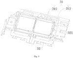
Fig. 4 illustrates a schematic view of a support of the mobile terminal shown inFig. 1 . -
Fig. 5 illustrates a schematic view of a middle frame of the mobile terminal shown inFig. 1 . -
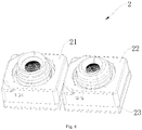
Fig. 6 illustrates a schematic view of a dual-camera assembly of the mobile terminal shown inFig. 1 . - Embodiments of the present disclosure will be described with reference to the accompanying drawings.
- As
Figs. 1 to 5 illustrated, embodiments of the present disclosure provide amobile terminal 100. Themobile terminal 100 includes amainboard 1 and a dual-camera module. The dual-camera module includes a dual-camera assembly 2 and ahousing assembly 3. Thehousing assembly 3 includes asupport 31 and amiddle frame 32. Thesupport 31 includes aperipheral side wall 311 and alug 312, theperipheral side wall 311 defines a firstaccommodating space 310 configured to accommodate the dual-camera assembly 2, and thelug 312 is connected to an outerperipheral side 3111 of theperipheral side wall 311 away from the first accommodating space. Themiddle frame 32 has a secondaccommodating space 320 and agroove 321 in communication with the secondaccommodating space 320, thesupport 31 is accommodated in the secondaccommodating space 320, and thelug 312 is fitted with thegroove 321. - In this embodiment, the fitting structure of the
lug 312 and thegroove 321 increases installation accuracy and connection firmness when thesupport 31 is installed to themiddle frame 32, such that the dual-camera assembly 2 accommodated in thesupport 31 is fixed relative to themiddle frame 32. Thus, thehousing assembly 3 can stabilize the dual-camera assembly 2, prevent the dual-camera assembly 2 from shaking or falling off relative to themiddle frame 32 during use of themobile terminal 100, and prolong service life of the dual-camera assembly 2. - The dual-
camera assembly 2 of the dual-camera module is accommodated in the firstaccommodating space 310. Themainboard 1 of themobile terminal 100 is fixed to themiddle frame 32 and electrically connected with the dual-camera assembly 2. Themobile terminal 100 can be a mobile phone, a notebook computer, a tablet computer or other electronic devices. - It could be understood that a shape of the outer
peripheral side 3111 of theperipheral side wall 311 matches a shape of an innerperipheral side 3201, configured to define the secondaccommodating space 320, of themiddle frame 32, such that thesupport 31 can be accommodated in the secondaccommodating space 320. A small gap is defined between the outerperipheral side 3111 of theperipheral side wall 311 and the innerperipheral side 3201 of themiddle frame 32, so as to reduce difficulty of installing thesupport 31 into themiddle frame 32, to avoid mutual abrasion during the installation, and to achieve initial position limit to each other. When thelug 312 is fitted with thegroove 321, at least two joint surfaces are formed to achieve the mutual position limit. - As an optional embodiment, the
support 31 is made of a metal material. Thesupport 31 made of the metal material has high strength and good toughness, and theperipheral side wall 311 has a small thickness and is able to save space, facilitating lighting and thinning of themobile terminal 100. Thelug 312 is grounded. After thesupport 31 is grounded through thelug 312, electric potential is lowered, and interference with an antenna electromagnetic signal can be reduced, improving user experience of themobile terminal 100. - The
support 31 can adopt an aluminum alloy material, a silver material, an iron material or the like. Thesupport 31 is molded through an automatic numerical control milling process acted on a metal block, i.e. a molding dimension of theperipheral side wall 311 and a molding dimension of thelug 312 are both realized through the numerical control milling process, such that theperipheral side wall 311 and thelug 312 have high dimensional precision. In this embodiment, theperipheral side wall 311 and thelug 312 are integrally molded. In another embodiment, thelug 312 can be connected to theperipheral side wall 311 by welding, screw joint or other ways. - As
Figs. 3 to 5 illustrated, as an optional embodiment, at least twolugs 312 are provided, and thelugs 312 are spaced apart and connected to theperipheral side wall 311. Thelugs 312 are spaced apart and connected to the outerperipheral side 3111 at a plurality of positions, so as to limit theperipheral side wall 311 from a plurality of directions and hence enhance the connection firmness when thesupport 31 is installed to themiddle frame 32. At this time, at least twogrooves 321 are also provided, and the number and positions of thegrooves 321 matches those of thelugs 312. - In an embodiment, the
lugs 312 can be arranged substantially uniformly around the outerperipheral side 3111 of theperipheral side wall 311, and a position of theperipheral side wall 311 is limited at multiple points which are distributed relatively uniformly in a circumferential direction to make thesupport 31 stressed uniformly in the circumferential direction. - Certainly, in other embodiments, the
lugs 312 are arranged more densely at a region where theperipheral side wall 311 is highly stressed, and thelugs 312 are arranged sparsely at a region where theperipheral side wall 311 is lightly stressed. - As shown in
Fig. 4 , as an optional embodiment, theperipheral side wall 311 includes twoshort walls 3112 arranged opposite to each other and two oppositelong walls 3113 connected between the twoshort walls 3112, at least one of theshort walls 3112 is provided with thelug 312, and at least one of thelong walls 3113 is provided with thelug 312. - In this embodiment, at least one of the
short walls 3112 is provided with thelug 312, such that a position of thesupport 31 is limited in an extension direction of theshort wall 3112; at least one of thelong walls 3113 is provided with thelug 312, such that the position of thesupport 31 is limited in an extension direction of thelong wall 3113. The extension direction of theshort wall 3112 intersects the extension direction of thelong wall 3113, such that the position of thesupport 31 is limited in at least two crossed directions and thesupport 31 is fixed relative to themiddle frame 32. - In an embodiment, the two
short walls 3112 and the twolong walls 3113 are all provided with thelugs 312. In another embodiment, oneshort wall 3112 is provided with thelug 312, and the twolong walls 3113 are provided with thelugs 312. In still another embodiment, the twoshort walls 3112 are provided with thelugs 312, and onelong wall 3113 is provided with thelug 312. - Optionally, each
short wall 3112 is provided with at least onelug 312, and eachlong wall 3113 is provided with at least onelug 312. - As
Figs. 4 and6 illustrated, as an optional embodiment, thesupport 31 further includes apartition wall 313 connected between the twolong walls 3113 and configured to divide the firstaccommodating space 310 into twoaccommodating sub-spaces camera assembly 2 includes afirst camera assembly 21 and asecond camera assembly 22, thefirst camera assembly 21 is accommodated in oneaccommodating sub-space 3101, and thesecond camera assembly 22 is accommodated in the otheraccommodating sub-space 3102. Thepartition wall 313 partitions thefirst camera assembly 21 from thesecond camera assembly 22 to avoid mutual collision between thefirst camera assembly 21 and thesecond camera assembly 22. Meanwhile, thepartition wall 313 can enhance the firmness of thesupport 31, and reduce a risk of squeezing the dual-camera assembly 2 due to deformation of thesupport 31 under the action of an external force. - The
partition wall 313 and theperipheral side wall 311 are integrally molded. Alternatively, thepartition wall 313 is connected to theperipheral side wall 311 by welding, screw joint or other ways. - Optionally, the
lug 312 provided to thelong wall 3113 is disposed directly facing thepartition wall 313, that is, thelug 312 is connected at the intersection of thelong wall 3113 and thepartition wall 313. Since the structural strength at the intersection of thelong wall 3113 and thepartition wall 313 is high, thelug 312 provided at the intersection is able to limit the position of theperipheral side wall 311, and deformation of theperipheral side wall 311 due to an excessive acting force produced by position limiting is avoided. - As
Figs. 2 to 6 illustrated, as an optional embodiment, themiddle frame 32 has aposition limiting step 322 protruding towards the secondaccommodating space 320. Theperipheral side wall 311 further includes anupper end surface 3115 and alower end surface 3116 disposed opposite to each other, and theupper end surface 3115 and thelower end surface 3116 are both connected to the outerperipheral side 3111. The end surface (theupper end surface 3115 or the lower end surface 3116) of theperipheral side wall 311 abuts against theposition limiting step 322. Theposition limiting step 322 is configured to limit the position of thesupport 31 and support thesupport 31. - Optionally, the dual-
camera assembly 2 is provided a blockingstep 23 in a circumferential side, and the end surface (theupper end surface 3115 or the lower end surface 3116) of theperipheral side wall 311 abuts against the blockingstep 23. Theperipheral side wall 311 limits the position of the dual-camera assembly 2 through the blockingstep 23. - In an embodiment, the
lower end surface 3116 of theperipheral side wall 311 abuts against the blockingstep 23, an upper portion of the dual-camera assembly 2 is accommodated in the firstaccommodating space 310, and a lower portion of the dual-camera assembly 2 extends out of the firstaccommodating space 310. Theposition limiting step 322 is located at a lower part of the secondaccommodating space 320 of themiddle frame 32. Thesupport 31 and the dual-camera assembly 2 are both accommodated in the secondaccommodating space 320, thelower end surface 3116 of theperipheral side wall 311 abuts against theposition limiting step 322, the position of thesupport 31 is limited at an upper part of the secondaccommodating space 320, and the lower portion of the dual-camera assembly 2 is accommodated in the lower part of the secondaccommodating space 320. In this embodiment, thesupport 31 presses the dual-camera assembly 2 to a certain position limiting zone (the lower part of the second accommodating space 320) of themiddle frame 32, thereby further stabilizing the dual-camera assembly 2. - Certainly, in other embodiments, the
upper end surface 3115 of theperipheral side wall 311 abuts against the blockingstep 23, and theposition limiting step 322 is located at the upper part of the secondaccommodating space 320. The upper portion of the dual-camera assembly 2 extends out of the firstaccommodating space 310, and the lower portion of the dual-camera assembly 2 is accommodated in the firstaccommodating space 310. Thesupport 31 and the dual-camera assembly 2 are both accommodated in the secondaccommodating space 320, theupper end surface 3115 of theperipheral side wall 311 abuts against theposition limiting step 322, the position of thesupport 31 is limited at the lower part of the secondaccommodating space 320, and the upper portion of the dual-camera assembly 2 is accommodated in the upper part of the secondaccommodating space 320. In this embodiment, thesupport 31 presses the dual-camera assembly 2 to the upper part of the secondaccommodating space 320 to limit the position of the dual-camera assembly 2. - It could be understood that the
groove 321 is in communication with a region of the secondaccommodating space 320 where theposition limiting step 322 is not provided, so as to facilitate the installation of thesupport 31 to themiddle frame 32. - As
Figs. 1 to 4 illustrated, as an optional embodiment, thehousing assembly 3 further includes arear cover 33, and therear cover 33 covers themiddle frame 32. Theperipheral side wall 311 is located between theposition limiting step 322 and therear cover 33. Therear cover 33 includes atop wall 331 and aside wall 332 surrounding thetop wall 331, and theside wall 332 abuts against themiddle frame 32 to realize closure. A throughhole 333 is provided at a position of therear cover 33 directly facing the twoaccommodating sub-spaces camera assembly 2. - Optionally, the
mainboard 1 is provided between therear cover 33 and thetop wall 331 of therear cover 33. Themainboard 1 is fixed to anupper end surface 323 of themiddle frame 32. - In an embodiment, a side of the
lug 312 away from thegroove 321 abuts against a ground pole of themainboard 1 through a conductive part, such that thesupport 31 is grounded, and the electric potential is lowered to reduce the interference with the antenna electromagnetic signal, thereby improving the user experience. The conductive part can be a conductive sponge or a metal elastic part. - In an embodiment, the through
hole 333 can include two through sub-holes spaced apart, and the through sub-holes are substantially circular. In another embodiment, the throughhole 333 can be a single hole exhibiting a runway circular shape. - Embodiments of the present disclosure have been described in detail, and principles and embodiments of the present disclosure have been elaborated with reference to specific examples, but the description of the above embodiments is merely used to assist in understanding the present disclosure and its core idea; meanwhile, it is conceivable for those skilled in the art to make changes in the specific embodiments and application areas according to the idea of the present disclosure. In conclusion, the description should not be construed to limit the present disclosure.
Claims (15)
- A housing assembly (3), comprising:a support (31) comprising a peripheral side wall (311) and a lug (312), the peripheral side wall (311) defining a first accommodating space (310), and the lug (312) being connected to an outer peripheral side (3111) of the peripheral side wall (311) away from the first accommodating space (310); anda middle frame (32) having a second accommodating space (320) and a groove (321) in communication with the second accommodating space (320), the support (31) being accommodated in the second accommodating space (320), and the lug (312) being fitted with the groove (321).
- The housing assembly (3) according to claim 1, wherein the support (31) is made of a metal material, and the lug (312) is grounded.
- The housing assembly (3) according to claim 1 or 2, wherein the peripheral side wall (311) and the lug (312) are integrally molded.
- The housing assembly (3) according to claim 1 or 2, wherein the lugs (312) can be arranged substantially uniformly around the outer peripheral side (3111) of the peripheral side wall (311).
- The housing assembly (3) according to claim 1 or 2, wherein the lugs (312) are provided at a first region in a first arrangement manner, and provided at a second region in a second arrangement manner, the first region is more highly stressed than the second region, and the lugs (312) are arranged more densely in the first arrangement manner than in the second arrangement.
- The housing assembly (3) according to claim 1 or 2, wherein at least two lugs (312) are provided; the peripheral side wall (311) comprises two short walls (3112) arranged opposite to each other and two opposite long walls (3113) connected between the two short walls (3112), at least one of the short walls (3112) being provided with the lug (312), and at least one of the long walls (3113) being provided with the lug (312).
- The housing assembly (3) according to claim 6, wherein the support (31) further comprises a partition wall (313) connected between the two long walls (3113) and configured to divide the first accommodating space (310) into two accommodating sub-spaces.
- The housing assembly (3) according to claim 7, wherein the lug (312) provided to the long wall (3113) is disposed facing the partition wall (313).
- The housing assembly (3) according to claim 7, wherein the partition wall (313) and the peripheral side wall (311) are integrally molded.
- The housing assembly (3) according to claim 1, wherein the middle frame (32) has a position limiting step (322) protruding towards the second accommodating space (320), and an end surface of the peripheral side wall (311) abuts against the position limiting step (322).
- The housing assembly (3) according to claim 10, further comprising a rear cover (33) covering the middle frame (32), the peripheral side wall (311) being located between the position limiting step (322) and the rear cover (33).
- A dual-camera module, characterized in that the dual-camera module comprises a dual-camera assembly (2) and a housing assembly (3) according to any one of claims 1 to 11, and
the dual-camera assembly (2) is accommodated in the first accommodating space (310). - The dual-camera module according to claim 12, wherein the dual-camera assembly (2) has a blocking step (23) provided at a peripheral side of the dual-camera assembly (2), and an end surface of a peripheral side wall (311) abuts against the blocking step (23).
- A mobile terminal, characterized in that the mobile terminal comprises a mainboard (1) and a dual-camera module according to claim 12 or 13,
and the mainboard (1) is fixed to the middle frame (32) and electrically connected to the dual-camera assembly (2). - The mobile terminal according to claim 14, wherein the dual-camera assembly (2) has a blocking step (23) provided at a peripheral side of the dual-camera assembly (2), and an end surface of a peripheral side wall (311) abuts against the blocking step (23).
Applications Claiming Priority (1)
| Application Number | Priority Date | Filing Date | Title |
|---|---|---|---|
| CN201621406333.5U CN206294254U (en) | 2016-12-20 | 2016-12-20 | Housing unit, dual camera module and mobile terminal |
Publications (2)
| Publication Number | Publication Date |
|---|---|
| EP3340006A1 true EP3340006A1 (en) | 2018-06-27 |
| EP3340006B1 EP3340006B1 (en) | 2020-01-08 |
Family
ID=59105156
Family Applications (1)
| Application Number | Title | Priority Date | Filing Date |
|---|---|---|---|
| EP17200985.4A Active EP3340006B1 (en) | 2016-12-20 | 2017-11-10 | Housing assembly, dual-camera module and mobile terminal |
Country Status (5)
| Country | Link |
|---|---|
| US (2) | US10412204B2 (en) |
| EP (1) | EP3340006B1 (en) |
| CN (1) | CN206294254U (en) |
| ES (1) | ES2771101T3 (en) |
| WO (1) | WO2018113178A1 (en) |
Cited By (1)
| Publication number | Priority date | Publication date | Assignee | Title |
|---|---|---|---|---|
| EP3451637A1 (en) * | 2017-08-28 | 2019-03-06 | Guangdong OPPO Mobile Telecommunications Corp., Ltd. | Decoration component, housing component and mobile terminal having same |
Families Citing this family (24)
| Publication number | Priority date | Publication date | Assignee | Title |
|---|---|---|---|---|
| CN107454221B (en) * | 2017-08-28 | 2020-07-24 | Oppo广东移动通信有限公司 | Decoration assembly, shell assembly, assembly method of shell assembly and mobile terminal |
| US10425561B2 (en) | 2017-09-08 | 2019-09-24 | Apple Inc. | Portable electronic device |
| CN107666805B (en) * | 2017-09-30 | 2019-12-31 | Oppo广东移动通信有限公司 | shell making method |
| CN107749904B (en) * | 2017-11-09 | 2019-06-25 | Oppo广东移动通信有限公司 | Mobile terminal and its camera module |
| CN107770313B (en) * | 2017-11-09 | 2019-06-25 | Oppo广东移动通信有限公司 | Mobile terminal and camera module thereof |
| WO2019091379A1 (en) | 2017-11-09 | 2019-05-16 | Guangdong Oppo Mobile Telecommunications Corp., Ltd. | Camera device, bracket and mobile terminal using same |
| CN207802016U (en) | 2017-11-09 | 2018-08-31 | 广东欧珀移动通信有限公司 | Mobile terminal and its camera module and holder |
| CN107734104A (en) * | 2017-11-29 | 2018-02-23 | 努比亚技术有限公司 | Glass back cover module and mobile terminal |
| CN110035202A (en) * | 2018-01-12 | 2019-07-19 | 深圳富泰宏精密工业有限公司 | Housing unit, electronic building brick mould group and the electronic device with electronic building brick mould group |
| TWI744461B (en) * | 2018-01-12 | 2021-11-01 | 群邁通訊股份有限公司 | Housing assembly, electronic module and electronic device with same |
| CN108234849A (en) * | 2018-01-31 | 2018-06-29 | 广东欧珀移动通信有限公司 | A kind of electronic device |
| CN108111651B (en) * | 2018-01-31 | 2024-01-12 | Oppo广东移动通信有限公司 | Camera fixing assembly, mounting method and electronic device |
| CN108234850B (en) * | 2018-01-31 | 2024-04-05 | Oppo广东移动通信有限公司 | Electronic device, camera fixing assembly and mounting method of camera fixing assembly |
| CN108377325A (en) * | 2018-05-21 | 2018-08-07 | Oppo广东移动通信有限公司 | Shooting device, electronic device and image acquisition method |
| CN108900763B (en) * | 2018-05-30 | 2022-03-22 | Oppo(重庆)智能科技有限公司 | Shooting device, electronic equipment and image acquisition method |
| CN108429883A (en) * | 2018-05-30 | 2018-08-21 | Oppo(重庆)智能科技有限公司 | Filming apparatus, electronic equipment and image acquiring method |
| CN108429882B (en) * | 2018-05-30 | 2020-08-25 | Oppo(重庆)智能科技有限公司 | Shooting device, electronic equipment and image acquisition method |
| CN108989506B (en) * | 2018-08-01 | 2020-06-05 | Oppo(重庆)智能科技有限公司 | Mobile terminal |
| CN109451111A (en) * | 2018-11-29 | 2019-03-08 | Oppo广东移动通信有限公司 | Electronic device |
| KR102774759B1 (en) * | 2019-01-22 | 2025-03-04 | 엘지이노텍 주식회사 | Camera Module |
| KR102841137B1 (en) * | 2019-09-27 | 2025-07-30 | 삼성전자주식회사 | A camera module and an electronic device comprising the same |
| CN113114876B (en) * | 2020-01-13 | 2022-09-27 | 荣耀终端有限公司 | Electronic equipment |
| CN112468624B (en) * | 2020-11-30 | 2022-08-19 | 维沃移动通信有限公司 | Electronic equipment and mounting method of support for electronic equipment |
| CN116095453B (en) * | 2021-10-30 | 2025-11-07 | 荣耀终端股份有限公司 | Camera support, camera subassembly and mobile terminal |
Citations (5)
| Publication number | Priority date | Publication date | Assignee | Title |
|---|---|---|---|---|
| KR20100066809A (en) * | 2008-12-10 | 2010-06-18 | 삼성전기주식회사 | Camera module package |
| US20100277640A1 (en) * | 2009-04-30 | 2010-11-04 | Shenzhen Futaihong Precision Industry Co., Ltd. | Camera apparatus for portable electronic device |
| CN104583830A (en) * | 2012-09-10 | 2015-04-29 | 磁化电子(株式会社) | Camera lens assembly |
| KR20160005927A (en) * | 2014-07-08 | 2016-01-18 | 자화전자(주) | Actuator for dual lens with common yoke and camera module including the same |
| CN106231018A (en) * | 2016-09-20 | 2016-12-14 | 深圳市金立通信设备有限公司 | A kind of dual camera module and terminal, the assembly method of dual camera module |
Family Cites Families (3)
| Publication number | Priority date | Publication date | Assignee | Title |
|---|---|---|---|---|
| CN201994976U (en) * | 2011-01-12 | 2011-09-28 | 瑞声光电科技(常州)有限公司 | Mobile phone and motor of camera of same |
| CN204305162U (en) * | 2014-11-28 | 2015-04-29 | 广东欧珀移动通信有限公司 | Double-camera device and terminal device thereof |
| CN106226887A (en) * | 2016-08-30 | 2016-12-14 | 金龙机电股份有限公司 | A kind of dual camera automatic focusing mechanism |
-
2016
- 2016-12-20 CN CN201621406333.5U patent/CN206294254U/en not_active Expired - Fee Related
-
2017
- 2017-05-19 WO PCT/CN2017/085055 patent/WO2018113178A1/en not_active Ceased
- 2017-11-03 US US15/802,697 patent/US10412204B2/en active Active
- 2017-11-10 EP EP17200985.4A patent/EP3340006B1/en active Active
- 2017-11-10 ES ES17200985T patent/ES2771101T3/en active Active
-
2019
- 2019-08-01 US US16/529,447 patent/US10530909B2/en active Active
Patent Citations (5)
| Publication number | Priority date | Publication date | Assignee | Title |
|---|---|---|---|---|
| KR20100066809A (en) * | 2008-12-10 | 2010-06-18 | 삼성전기주식회사 | Camera module package |
| US20100277640A1 (en) * | 2009-04-30 | 2010-11-04 | Shenzhen Futaihong Precision Industry Co., Ltd. | Camera apparatus for portable electronic device |
| CN104583830A (en) * | 2012-09-10 | 2015-04-29 | 磁化电子(株式会社) | Camera lens assembly |
| KR20160005927A (en) * | 2014-07-08 | 2016-01-18 | 자화전자(주) | Actuator for dual lens with common yoke and camera module including the same |
| CN106231018A (en) * | 2016-09-20 | 2016-12-14 | 深圳市金立通信设备有限公司 | A kind of dual camera module and terminal, the assembly method of dual camera module |
Cited By (1)
| Publication number | Priority date | Publication date | Assignee | Title |
|---|---|---|---|---|
| EP3451637A1 (en) * | 2017-08-28 | 2019-03-06 | Guangdong OPPO Mobile Telecommunications Corp., Ltd. | Decoration component, housing component and mobile terminal having same |
Also Published As
| Publication number | Publication date |
|---|---|
| US20190356764A1 (en) | 2019-11-21 |
| ES2771101T3 (en) | 2020-07-06 |
| EP3340006B1 (en) | 2020-01-08 |
| US10530909B2 (en) | 2020-01-07 |
| US10412204B2 (en) | 2019-09-10 |
| CN206294254U (en) | 2017-06-30 |
| WO2018113178A1 (en) | 2018-06-28 |
| US20180176350A1 (en) | 2018-06-21 |
Similar Documents
| Publication | Publication Date | Title |
|---|---|---|
| US10530909B2 (en) | Housing assembly, dual-camera module and mobile terminal | |
| US10306032B2 (en) | Bracket assembly, camera module, and mobile terminal | |
| US10165161B2 (en) | Bracket assembly for mobile terminal and mobile terminal | |
| KR101808940B1 (en) | Antenna link in ultra-thin device with single-piece metal housing | |
| US10320961B2 (en) | Bracket assembly for functional component for mobile terminal | |
| KR102419622B1 (en) | Structure for filtering noise on at least one designated band out and electronic device including the same | |
| US20180226740A1 (en) | Receptacle connector | |
| US20060189183A1 (en) | Camera module connector | |
| CN104811589A (en) | Portable electronic device and camera module set thereof | |
| US20080166921A1 (en) | Shielded connector | |
| CN107611571B (en) | Elastic parts, functional components and mobile terminals | |
| US9437960B2 (en) | Dustproof cover for charging port of electronic device and charging base corresponding to dustproof cover | |
| US11217879B2 (en) | Antenna assembly and electronic device using same | |
| US11158932B2 (en) | Full screen electronic device and antenna thereof | |
| CN104811590A (en) | Portable electronic device and camera module set thereof | |
| US7059875B2 (en) | Ground metal fitting and ground structure for jacks of electronic devices | |
| EP3809524A1 (en) | Human body distance detection module for electronic device, electronic device and control method thereof | |
| US9733675B2 (en) | Elastic body and electronic device | |
| US9147934B2 (en) | Antenna structure configured to RF shieldings | |
| CN207135145U (en) | Elastic parts, functional components and mobile terminals | |
| CN214754131U (en) | Three proofings 5G antenna structure | |
| CN114980634B (en) | Electronic devices | |
| CN207134485U (en) | Elastic component, functional unit and mobile terminal |
Legal Events
| Date | Code | Title | Description |
|---|---|---|---|
| PUAI | Public reference made under article 153(3) epc to a published international application that has entered the european phase |
Free format text: ORIGINAL CODE: 0009012 |
|
| STAA | Information on the status of an ep patent application or granted ep patent |
Free format text: STATUS: REQUEST FOR EXAMINATION WAS MADE |
|
| 17P | Request for examination filed |
Effective date: 20171110 |
|
| AK | Designated contracting states |
Kind code of ref document: A1 Designated state(s): AL AT BE BG CH CY CZ DE DK EE ES FI FR GB GR HR HU IE IS IT LI LT LU LV MC MK MT NL NO PL PT RO RS SE SI SK SM TR |
|
| AX | Request for extension of the european patent |
Extension state: BA ME |
|
| STAA | Information on the status of an ep patent application or granted ep patent |
Free format text: STATUS: EXAMINATION IS IN PROGRESS |
|
| 17Q | First examination report despatched |
Effective date: 20181102 |
|
| GRAP | Despatch of communication of intention to grant a patent |
Free format text: ORIGINAL CODE: EPIDOSNIGR1 |
|
| STAA | Information on the status of an ep patent application or granted ep patent |
Free format text: STATUS: GRANT OF PATENT IS INTENDED |
|
| RIC1 | Information provided on ipc code assigned before grant |
Ipc: H04N 5/225 20060101ALI20190812BHEP Ipc: H04M 1/02 20060101ALI20190812BHEP Ipc: H04N 7/14 20060101ALI20190812BHEP Ipc: G06F 1/16 20060101AFI20190812BHEP Ipc: H04N 5/232 20060101ALI20190812BHEP |
|
| INTG | Intention to grant announced |
Effective date: 20190904 |
|
| GRAS | Grant fee paid |
Free format text: ORIGINAL CODE: EPIDOSNIGR3 |
|
| GRAA | (expected) grant |
Free format text: ORIGINAL CODE: 0009210 |
|
| STAA | Information on the status of an ep patent application or granted ep patent |
Free format text: STATUS: THE PATENT HAS BEEN GRANTED |
|
| RAP1 | Party data changed (applicant data changed or rights of an application transferred) |
Owner name: GUANGDONG OPPO MOBILE TELECOMMUNICATIONS CORP., LT |
|
| AK | Designated contracting states |
Kind code of ref document: B1 Designated state(s): AL AT BE BG CH CY CZ DE DK EE ES FI FR GB GR HR HU IE IS IT LI LT LU LV MC MK MT NL NO PL PT RO RS SE SI SK SM TR |
|
| REG | Reference to a national code |
Ref country code: GB Ref legal event code: FG4D |
|
| REG | Reference to a national code |
Ref country code: CH Ref legal event code: EP |
|
| REG | Reference to a national code |
Ref country code: DE Ref legal event code: R096 Ref document number: 602017010634 Country of ref document: DE |
|
| REG | Reference to a national code |
Ref country code: IE Ref legal event code: FG4D |
|
| REG | Reference to a national code |
Ref country code: AT Ref legal event code: REF Ref document number: 1223486 Country of ref document: AT Kind code of ref document: T Effective date: 20200215 |
|
| REG | Reference to a national code |
Ref country code: NL Ref legal event code: FP |
|
| REG | Reference to a national code |
Ref country code: ES Ref legal event code: FG2A Ref document number: 2771101 Country of ref document: ES Kind code of ref document: T3 Effective date: 20200706 |
|
| REG | Reference to a national code |
Ref country code: LT Ref legal event code: MG4D |
|
| PG25 | Lapsed in a contracting state [announced via postgrant information from national office to epo] |
Ref country code: LT Free format text: LAPSE BECAUSE OF FAILURE TO SUBMIT A TRANSLATION OF THE DESCRIPTION OR TO PAY THE FEE WITHIN THE PRESCRIBED TIME-LIMIT Effective date: 20200108 Ref country code: RS Free format text: LAPSE BECAUSE OF FAILURE TO SUBMIT A TRANSLATION OF THE DESCRIPTION OR TO PAY THE FEE WITHIN THE PRESCRIBED TIME-LIMIT Effective date: 20200108 Ref country code: PT Free format text: LAPSE BECAUSE OF FAILURE TO SUBMIT A TRANSLATION OF THE DESCRIPTION OR TO PAY THE FEE WITHIN THE PRESCRIBED TIME-LIMIT Effective date: 20200531 Ref country code: FI Free format text: LAPSE BECAUSE OF FAILURE TO SUBMIT A TRANSLATION OF THE DESCRIPTION OR TO PAY THE FEE WITHIN THE PRESCRIBED TIME-LIMIT Effective date: 20200108 Ref country code: NO Free format text: LAPSE BECAUSE OF FAILURE TO SUBMIT A TRANSLATION OF THE DESCRIPTION OR TO PAY THE FEE WITHIN THE PRESCRIBED TIME-LIMIT Effective date: 20200408 |
|
| PG25 | Lapsed in a contracting state [announced via postgrant information from national office to epo] |
Ref country code: BG Free format text: LAPSE BECAUSE OF FAILURE TO SUBMIT A TRANSLATION OF THE DESCRIPTION OR TO PAY THE FEE WITHIN THE PRESCRIBED TIME-LIMIT Effective date: 20200408 Ref country code: HR Free format text: LAPSE BECAUSE OF FAILURE TO SUBMIT A TRANSLATION OF THE DESCRIPTION OR TO PAY THE FEE WITHIN THE PRESCRIBED TIME-LIMIT Effective date: 20200108 Ref country code: GR Free format text: LAPSE BECAUSE OF FAILURE TO SUBMIT A TRANSLATION OF THE DESCRIPTION OR TO PAY THE FEE WITHIN THE PRESCRIBED TIME-LIMIT Effective date: 20200409 Ref country code: IS Free format text: LAPSE BECAUSE OF FAILURE TO SUBMIT A TRANSLATION OF THE DESCRIPTION OR TO PAY THE FEE WITHIN THE PRESCRIBED TIME-LIMIT Effective date: 20200508 Ref country code: SE Free format text: LAPSE BECAUSE OF FAILURE TO SUBMIT A TRANSLATION OF THE DESCRIPTION OR TO PAY THE FEE WITHIN THE PRESCRIBED TIME-LIMIT Effective date: 20200108 Ref country code: LV Free format text: LAPSE BECAUSE OF FAILURE TO SUBMIT A TRANSLATION OF THE DESCRIPTION OR TO PAY THE FEE WITHIN THE PRESCRIBED TIME-LIMIT Effective date: 20200108 |
|
| REG | Reference to a national code |
Ref country code: DE Ref legal event code: R097 Ref document number: 602017010634 Country of ref document: DE |
|
| PG25 | Lapsed in a contracting state [announced via postgrant information from national office to epo] |
Ref country code: CZ Free format text: LAPSE BECAUSE OF FAILURE TO SUBMIT A TRANSLATION OF THE DESCRIPTION OR TO PAY THE FEE WITHIN THE PRESCRIBED TIME-LIMIT Effective date: 20200108 Ref country code: RO Free format text: LAPSE BECAUSE OF FAILURE TO SUBMIT A TRANSLATION OF THE DESCRIPTION OR TO PAY THE FEE WITHIN THE PRESCRIBED TIME-LIMIT Effective date: 20200108 Ref country code: SK Free format text: LAPSE BECAUSE OF FAILURE TO SUBMIT A TRANSLATION OF THE DESCRIPTION OR TO PAY THE FEE WITHIN THE PRESCRIBED TIME-LIMIT Effective date: 20200108 Ref country code: EE Free format text: LAPSE BECAUSE OF FAILURE TO SUBMIT A TRANSLATION OF THE DESCRIPTION OR TO PAY THE FEE WITHIN THE PRESCRIBED TIME-LIMIT Effective date: 20200108 Ref country code: DK Free format text: LAPSE BECAUSE OF FAILURE TO SUBMIT A TRANSLATION OF THE DESCRIPTION OR TO PAY THE FEE WITHIN THE PRESCRIBED TIME-LIMIT Effective date: 20200108 Ref country code: SM Free format text: LAPSE BECAUSE OF FAILURE TO SUBMIT A TRANSLATION OF THE DESCRIPTION OR TO PAY THE FEE WITHIN THE PRESCRIBED TIME-LIMIT Effective date: 20200108 |
|
| PLBE | No opposition filed within time limit |
Free format text: ORIGINAL CODE: 0009261 |
|
| STAA | Information on the status of an ep patent application or granted ep patent |
Free format text: STATUS: NO OPPOSITION FILED WITHIN TIME LIMIT |
|
| REG | Reference to a national code |
Ref country code: AT Ref legal event code: MK05 Ref document number: 1223486 Country of ref document: AT Kind code of ref document: T Effective date: 20200108 |
|
| 26N | No opposition filed |
Effective date: 20201009 |
|
| PG25 | Lapsed in a contracting state [announced via postgrant information from national office to epo] |
Ref country code: AT Free format text: LAPSE BECAUSE OF FAILURE TO SUBMIT A TRANSLATION OF THE DESCRIPTION OR TO PAY THE FEE WITHIN THE PRESCRIBED TIME-LIMIT Effective date: 20200108 |
|
| PG25 | Lapsed in a contracting state [announced via postgrant information from national office to epo] |
Ref country code: SI Free format text: LAPSE BECAUSE OF FAILURE TO SUBMIT A TRANSLATION OF THE DESCRIPTION OR TO PAY THE FEE WITHIN THE PRESCRIBED TIME-LIMIT Effective date: 20200108 Ref country code: PL Free format text: LAPSE BECAUSE OF FAILURE TO SUBMIT A TRANSLATION OF THE DESCRIPTION OR TO PAY THE FEE WITHIN THE PRESCRIBED TIME-LIMIT Effective date: 20200108 |
|
| PG25 | Lapsed in a contracting state [announced via postgrant information from national office to epo] |
Ref country code: MC Free format text: LAPSE BECAUSE OF FAILURE TO SUBMIT A TRANSLATION OF THE DESCRIPTION OR TO PAY THE FEE WITHIN THE PRESCRIBED TIME-LIMIT Effective date: 20200108 |
|
| REG | Reference to a national code |
Ref country code: CH Ref legal event code: PL |
|
| PG25 | Lapsed in a contracting state [announced via postgrant information from national office to epo] |
Ref country code: LU Free format text: LAPSE BECAUSE OF NON-PAYMENT OF DUE FEES Effective date: 20201110 |
|
| REG | Reference to a national code |
Ref country code: BE Ref legal event code: MM Effective date: 20201130 |
|
| PG25 | Lapsed in a contracting state [announced via postgrant information from national office to epo] |
Ref country code: LI Free format text: LAPSE BECAUSE OF NON-PAYMENT OF DUE FEES Effective date: 20201130 Ref country code: CH Free format text: LAPSE BECAUSE OF NON-PAYMENT OF DUE FEES Effective date: 20201130 |
|
| PG25 | Lapsed in a contracting state [announced via postgrant information from national office to epo] |
Ref country code: IE Free format text: LAPSE BECAUSE OF NON-PAYMENT OF DUE FEES Effective date: 20201110 |
|
| PG25 | Lapsed in a contracting state [announced via postgrant information from national office to epo] |
Ref country code: TR Free format text: LAPSE BECAUSE OF FAILURE TO SUBMIT A TRANSLATION OF THE DESCRIPTION OR TO PAY THE FEE WITHIN THE PRESCRIBED TIME-LIMIT Effective date: 20200108 Ref country code: MT Free format text: LAPSE BECAUSE OF FAILURE TO SUBMIT A TRANSLATION OF THE DESCRIPTION OR TO PAY THE FEE WITHIN THE PRESCRIBED TIME-LIMIT Effective date: 20200108 Ref country code: CY Free format text: LAPSE BECAUSE OF FAILURE TO SUBMIT A TRANSLATION OF THE DESCRIPTION OR TO PAY THE FEE WITHIN THE PRESCRIBED TIME-LIMIT Effective date: 20200108 |
|
| PG25 | Lapsed in a contracting state [announced via postgrant information from national office to epo] |
Ref country code: MK Free format text: LAPSE BECAUSE OF FAILURE TO SUBMIT A TRANSLATION OF THE DESCRIPTION OR TO PAY THE FEE WITHIN THE PRESCRIBED TIME-LIMIT Effective date: 20200108 Ref country code: AL Free format text: LAPSE BECAUSE OF FAILURE TO SUBMIT A TRANSLATION OF THE DESCRIPTION OR TO PAY THE FEE WITHIN THE PRESCRIBED TIME-LIMIT Effective date: 20200108 |
|
| PG25 | Lapsed in a contracting state [announced via postgrant information from national office to epo] |
Ref country code: BE Free format text: LAPSE BECAUSE OF NON-PAYMENT OF DUE FEES Effective date: 20201130 |
|
| P01 | Opt-out of the competence of the unified patent court (upc) registered |
Effective date: 20230412 |
|
| PGFP | Annual fee paid to national office [announced via postgrant information from national office to epo] |
Ref country code: ES Payment date: 20231215 Year of fee payment: 7 |
|
| PGFP | Annual fee paid to national office [announced via postgrant information from national office to epo] |
Ref country code: IT Payment date: 20231130 Year of fee payment: 7 Ref country code: FR Payment date: 20231121 Year of fee payment: 7 |
|
| PG25 | Lapsed in a contracting state [announced via postgrant information from national office to epo] |
Ref country code: IT Free format text: LAPSE BECAUSE OF NON-PAYMENT OF DUE FEES Effective date: 20241110 |
|
| PG25 | Lapsed in a contracting state [announced via postgrant information from national office to epo] |
Ref country code: FR Free format text: LAPSE BECAUSE OF NON-PAYMENT OF DUE FEES Effective date: 20241130 |
|
| PGFP | Annual fee paid to national office [announced via postgrant information from national office to epo] |
Ref country code: NL Payment date: 20251127 Year of fee payment: 9 |
|
| REG | Reference to a national code |
Ref country code: ES Ref legal event code: FD2A Effective date: 20260105 |
|
| PGFP | Annual fee paid to national office [announced via postgrant information from national office to epo] |
Ref country code: DE Payment date: 20251124 Year of fee payment: 9 |
|
| PGFP | Annual fee paid to national office [announced via postgrant information from national office to epo] |
Ref country code: GB Payment date: 20251126 Year of fee payment: 9 |
|
| PG25 | Lapsed in a contracting state [announced via postgrant information from national office to epo] |
Ref country code: ES Free format text: LAPSE BECAUSE OF NON-PAYMENT OF DUE FEES Effective date: 20241111 |